EP2581984B1 - Verfahren zum Prüfen einer Antennenspule - Google Patents
Verfahren zum Prüfen einer Antennenspule Download PDFInfo
- Publication number
- EP2581984B1 EP2581984B1 EP12006295.5A EP12006295A EP2581984B1 EP 2581984 B1 EP2581984 B1 EP 2581984B1 EP 12006295 A EP12006295 A EP 12006295A EP 2581984 B1 EP2581984 B1 EP 2581984B1
- Authority
- EP
- European Patent Office
- Prior art keywords
- antenna coil
- coil
- open
- antenna
- closed
- Prior art date
- Legal status (The legal status is an assumption and is not a legal conclusion. Google has not performed a legal analysis and makes no representation as to the accuracy of the status listed.)
- Active
Links
- 238000000034 method Methods 0.000 title claims description 34
- 238000012360 testing method Methods 0.000 title description 43
- 230000010355 oscillation Effects 0.000 claims description 34
- 239000004020 conductor Substances 0.000 claims description 28
- 230000005284 excitation Effects 0.000 claims description 25
- 239000012876 carrier material Substances 0.000 claims description 15
- 238000010998 test method Methods 0.000 description 23
- 238000004519 manufacturing process Methods 0.000 description 15
- 238000005259 measurement Methods 0.000 description 11
- 239000010410 layer Substances 0.000 description 8
- 238000011156 evaluation Methods 0.000 description 7
- 230000004907 flux Effects 0.000 description 5
- 239000011888 foil Substances 0.000 description 5
- 229910052751 metal Inorganic materials 0.000 description 5
- 239000002184 metal Substances 0.000 description 5
- 230000002238 attenuated effect Effects 0.000 description 4
- 230000007547 defect Effects 0.000 description 4
- 239000002356 single layer Substances 0.000 description 3
- 239000000758 substrate Substances 0.000 description 3
- 238000004804 winding Methods 0.000 description 3
- 241000084490 Esenbeckia delta Species 0.000 description 2
- 230000003466 anti-cipated effect Effects 0.000 description 2
- 239000000969 carrier Substances 0.000 description 2
- 230000007812 deficiency Effects 0.000 description 2
- 230000001419 dependent effect Effects 0.000 description 2
- 238000003780 insertion Methods 0.000 description 2
- 230000037431 insertion Effects 0.000 description 2
- 238000007790 scraping Methods 0.000 description 2
- 230000035939 shock Effects 0.000 description 2
- BQCADISMDOOEFD-UHFFFAOYSA-N Silver Chemical compound [Ag] BQCADISMDOOEFD-UHFFFAOYSA-N 0.000 description 1
- 239000002313 adhesive film Substances 0.000 description 1
- 238000013459 approach Methods 0.000 description 1
- 230000005540 biological transmission Effects 0.000 description 1
- 230000015572 biosynthetic process Effects 0.000 description 1
- 238000004891 communication Methods 0.000 description 1
- 230000002950 deficient Effects 0.000 description 1
- 238000001514 detection method Methods 0.000 description 1
- 238000011161 development Methods 0.000 description 1
- 230000018109 developmental process Effects 0.000 description 1
- 238000005516 engineering process Methods 0.000 description 1
- 230000002452 interceptive effect Effects 0.000 description 1
- 239000000463 material Substances 0.000 description 1
- 239000012811 non-conductive material Substances 0.000 description 1
- 230000003071 parasitic effect Effects 0.000 description 1
- 230000000704 physical effect Effects 0.000 description 1
- 238000007639 printing Methods 0.000 description 1
- 238000004080 punching Methods 0.000 description 1
- 239000000523 sample Substances 0.000 description 1
- 229910052709 silver Inorganic materials 0.000 description 1
- 239000004332 silver Substances 0.000 description 1
- 239000011343 solid material Substances 0.000 description 1
- 230000001052 transient effect Effects 0.000 description 1
Images


Classifications
-
- H—ELECTRICITY
- H01—ELECTRIC ELEMENTS
- H01Q—ANTENNAS, i.e. RADIO AERIALS
- H01Q7/00—Loop antennas with a substantially uniform current distribution around the loop and having a directional radiation pattern in a plane perpendicular to the plane of the loop
-
- H—ELECTRICITY
- H01—ELECTRIC ELEMENTS
- H01Q—ANTENNAS, i.e. RADIO AERIALS
- H01Q1/00—Details of, or arrangements associated with, antennas
- H01Q1/12—Supports; Mounting means
- H01Q1/22—Supports; Mounting means by structural association with other equipment or articles
- H01Q1/2208—Supports; Mounting means by structural association with other equipment or articles associated with components used in interrogation type services, i.e. in systems for information exchange between an interrogator/reader and a tag/transponder, e.g. in Radio Frequency Identification [RFID] systems
-
- H—ELECTRICITY
- H01—ELECTRIC ELEMENTS
- H01Q—ANTENNAS, i.e. RADIO AERIALS
- H01Q1/00—Details of, or arrangements associated with, antennas
- H01Q1/36—Structural form of radiating elements, e.g. cone, spiral, umbrella; Particular materials used therewith
- H01Q1/38—Structural form of radiating elements, e.g. cone, spiral, umbrella; Particular materials used therewith formed by a conductive layer on an insulating support
-
- H—ELECTRICITY
- H04—ELECTRIC COMMUNICATION TECHNIQUE
- H04B—TRANSMISSION
- H04B17/00—Monitoring; Testing
- H04B17/10—Monitoring; Testing of transmitters
- H04B17/11—Monitoring; Testing of transmitters for calibration
- H04B17/12—Monitoring; Testing of transmitters for calibration of transmit antennas, e.g. of the amplitude or phase
-
- H—ELECTRICITY
- H04—ELECTRIC COMMUNICATION TECHNIQUE
- H04B—TRANSMISSION
- H04B5/00—Near-field transmission systems, e.g. inductive or capacitive transmission systems
- H04B5/20—Near-field transmission systems, e.g. inductive or capacitive transmission systems characterised by the transmission technique; characterised by the transmission medium
- H04B5/24—Inductive coupling
- H04B5/26—Inductive coupling using coils
-
- H—ELECTRICITY
- H04—ELECTRIC COMMUNICATION TECHNIQUE
- H04B—TRANSMISSION
- H04B5/00—Near-field transmission systems, e.g. inductive or capacitive transmission systems
- H04B5/40—Near-field transmission systems, e.g. inductive or capacitive transmission systems characterised by components specially adapted for near-field transmission
- H04B5/43—Antennas
Definitions
- the present invention relates to a method for testing the operability of an antenna coil for a portable data carrier.
- Portable data carriers such as a personal ID card, passport, credit card, retail security label or the like may be equipped with an antenna coil for contactless data communication with a reader.
- the antenna coil is usually connected to an integrated circuit of the data carrier, in particular a chip, and applied to a carrier or inlay layer, for example of a plastic material such as PC or PVC, a data carrier body of the data carrier, for example, printed.
- the resonant frequency of the antenna coil and its quality can be determined contactless.
- a phase and impedance analyzer is usually used.
- Such a very complex process is detailed, for example, in " RFID Handbook "by Klaus Finkenzeller, 5th edition, Carl Hanser Verlag, Kunststoff, 2008, in chapter 4.1.11.2 , described. If the measured resonance frequency is within a predetermined range, then the antenna coil is functional. This type of test is more meaningful than a purely ohmic measurement, but much more complex and best done manually. The duration of such a test is in the range of several seconds. Therefore, this test is usually not carried out during production, but only on a few samples and for production release.
- Object of the present invention is therefore to propose a method for reliable functional testing of an antenna coil without connected integrated circuit. Desirably This test is still fast, easy to perform and cost effective.
- the invention is based on the idea of closing an antenna coil without connected integrated circuit, which as a rule is present as an open antenna coil, by means of a contacting short-circuit bridge before contactless testing and subsequently testing the closed antenna coil. In this way, as explained in detail below, reliably detect errors of the antenna coil, especially those which are very close to the ends of a formerly open antenna coil.
- a method for testing the functionality of an antenna coil for a contactlessly communicating portable data carrier comprises the following steps: In a first step, the functionality of a closed antenna coil is tested contactless. If the antenna coil under test is originally present as an open antenna coil, the antenna coil is shorted in a suitable manner, described in detail below, prior to the step of testing. But it is also possible that the antenna coil already made in the production as a closed coil, for example, printed, is. In this case, an area for later interrupting the closed coil can be provided, in which then, for example, an integrated circuit can be used and connected to the then open antenna coil.
- the step of testing itself can then be carried out with a known contactless test method explained, for example, in the introduction to the description, that is to say by measuring the impedance of the antenna coil, a determination of the resonant frequency or the quality of the antenna coil.
- the method according to the invention makes it possible in a simple manner to detect faults, in particular line breaks, in an antenna coil, in particular those faults which occur very close to the contacting ends of an antenna coil. Namely, if an open antenna coil is tested with a conventional contactless test method, such a method recognizes the error described in principle or hardly, since the physical properties of a conductor portion of such a faulty, open antenna coil, if the conductor track part is large enough, hardly from the physical Characteristics of an intact coil are distinguished, since the corresponding line lengths are not sufficiently different from each other.
- this new contactless test method comprises the following sub-steps:
- a first sub-step the antenna coil is excited to vibrate.
- a pulsed magnetic field which can be generated, for example, in a simple manner by a single (DC) current pulse.
- the excitation consists of a single magnetic field pulse.
- the DC pulse can be generated as a Dirac shock.
- the magnetic field is generated by a (DC) current pulse, which - unlike a Dirac shock - only has a steep edge.
- the exciting of the antenna coil is effected contactlessly via an excitation coil, which is coupled thereto with a corresponding pulse generator.
- the free, damped oscillation of the antenna coil which is generated in response to the excitation, is detected. This is preferably also done without contact by means of a measuring antenna. Excitation coil and measuring antenna are preferably arranged in the immediate vicinity of the antenna coil to be tested.
- the detected free, damped oscillation of the antenna coil is evaluated. This can be done by means of a suitable evaluation device, which is connected to the measuring antenna.
- the evaluation device can in particular use a comparison with reference values of an intact antenna coil.
- a digital signal processor (DSP) or an oscilloscope can be used in a known manner, for example.
- a (t) may correspond to the current I or the voltage U of an electrical resonant circuit formed by the antenna coil.
- the angular frequency ⁇ corresponds to the natural resonance frequency of the antenna coil. From the decay coefficient ⁇ , the quality of the antenna coil can be determined. The longer the decay process lasts, the higher the quality of the corresponding resonant circuit. That an evaluation of the free attenuated oscillation of the antenna coil, d. H. their decay immediately after the excitation, it allows to determine both the natural frequency and the quality of the antenna coil.
- the applicability of the contactless test method is based on the fact that a defect of the antenna coil to be tested, such as an interruption of a conductor track or a short circuit between individual coil windings of the antenna coil, leads to a noticeable in a test described waveform of the swinging significantly from a different waveform of the swinging out of an intact antenna coil. Based on the evaluated free, damped vibration detected parameters of a faulty Coil, in particular their natural resonance frequency and their quality, differ significantly from the corresponding parameters of an intact antenna coil.
- a conductor break for example, is reflected in a clearly recognizable changed decay behavior, in particular an altered, usually increased natural resonant frequency. In the case of a short circuit of two or more coil turns barring is no longer observed.
- the advantages of the contactless testing method are obvious and numerous.
- the examination of the antenna coil can be carried out without contact, with a very short time and thus in particular during an ongoing production process.
- even a printed antenna coil, which has not yet completely cured can be tested with the method according to the invention.
- the required testing device is comparatively easy and inexpensive to provide.
- the method not only allows to detect errors or deficiencies of a defective antenna coil, but also to distinguish different types of errors.
- the method also allows with an unchanged structure both a testing of unpopulated antenna coils, ie those which are not yet connected to an integrated circuit, as well as antenna coils with connected circuit, such as already completed transponders or contactlessly communicating chip cards.
- the method can be carried out in parallel for a plurality of antennas, which are arranged, for example, side by side on a production sheet, without the need for shielding individual antennas.
- antenna coils can thus be tested by means of this method quickly, easily and inexpensively in terms of their functionality.
- the excitation coil and the measuring antenna for checking the antenna coil or in the test apparatus are arranged "orthogonal" to each other.
- the exciting coil and the measuring antenna are arranged not orthogonal to each other, but for example next to each other, the excitation pulse of the exciting coil is also detected by the measuring antenna.
- the Abschwing the exciter coil then superimposed on the Abschwing the antenna coil to be measured.
- the excitation coil In an "orthogonal" arrangement of the excitation coil to the measuring antenna, these are such to each other that the signal of the excitation coil is not perceived by the measuring antenna.
- the excitation coil is arranged spatially relative to the measuring antenna in such a way that substantially no signal is coupled into the measuring antenna.
- a signal is coupled into a coil whenever the ring integral across the magnetic flux ⁇ through this coil is greater than zero (see RFID Handbook, chapters 4.1.6 and 4.1.9.2 cited above).
- the integral over the magnetic flux ⁇ is zero if and only if magnetic field lines of different direction and field strength in the measuring antenna over the total area cancel each other, or if the angle of the field lines to the coil axis is exactly 90 ° - hence the term "orthogonal" arrangement.
- the antenna coil to be tested can initially be closed in the context of the test method according to the invention.
- the then emerging in the step of breaking ends of a conductor of the then open antenna coil can serve as terminals for components of an integrated circuit, in particular a chip.
- the ends of the open antenna coil can also be bridged temporarily by means of an external bridging device, preferably in the form of a roller described in detail below.
- an external bridging device preferably in the form of a roller described in detail below.
- This type of bridging is preferably used when the distance between the ends of an open antenna coil to be bridged is so small that a subsequent removal of the bridging for interrupting a conductor track of the antenna coil at the same location would be very costly due to the low tolerances.
- the manner in which the step of interrupting a trace of the antenna coil after the contactless check is actually performed depends on how the open antenna coil has been previously closed.
- the interruption usually takes place simply by removing the bridging device.
- the already only temporarily applied connection of the open ends of the antenna coil can be performed in this way without interfering with the structure of the antenna coil and / or the carrier material.
- the interruption of the conductor track of the now-tested, closed antenna coil is effected by removing a part of the closed conductor track, preferably in the region previously the shorting bridge has been arranged. This can be done in various ways, for example by punching out a corresponding region in the carrier layer, which can then serve for example for insertion of the integrated circuit. However, a portion of the trace may also be removed by laser, by mechanical "scraping", or by other suitable means.
- the step of non-contact testing of the antenna coil is carried out again with regard to its functionality after the step of interrupting the closed antenna coil. This can be done again with one of the contactless test methods described above.
- the test method newly presented in detail in the context of this invention and described in detail above, which is based on an evaluation of the transient response of the antenna coil tested is preferably used.
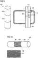
- a bridging device for temporarily bridging the ends of an open antenna coil arranged on a carrier material for a contactlessly communicating portable data carrier is characterized in that the bridging device is designed as an at least partially electrically conductive pressure roller.
- This roller is typically formed as a part of a conveyor system of an apparatus for producing the antenna coil and is arranged to bridge the ends of the open antenna coil such that a closed conductor path is formed when the carrier material is conveyed under the pressure roller.
- the radius of the pressure roller is selected such that a bearing surface of the pressure roller on the carrier material simultaneously contacts the ends of the open antenna coil when the carrier material is conveyed under the pressure roller.
- the pressure roller consists to a large extent of an electrically non-conductive material, for example Plastic. Only in a limited area, in which the ends of the open antenna coil are conveyed under the roller, an electrically conductive portion, preferably only on a surface of the roller, is provided, for example in the form of a metal foil.
- the pressure roller is formed such that the electrically conductive portion of the pressure roller coaxially on the surface of the pressure roller extending conductive segments, each of which conductive segments are separated.
- the conductive segments can be arranged for example in the form of metal foil strips on the roller. It is understood that the width of the electrically conductive strip is preferably chosen so that when an arc is conveyed through with the carrier carrying the antenna coils under the roller, at least one such strip on the substrate comes to rest such that the ends the open antenna coil are connected, ie that temporarily creates a closed antenna coil.
- FIG. 1 and 2 For example, two different inlay layers 10 of a portable data carrier, in the example of a chip card shown, with antenna coil 20 arranged thereon are shown.
- the antenna coil 20 can be applied on both sides, wherein a through-hole is then necessary to form a crossing point.
- an intersection is formed by means of a bridge (bottom right in the figure).
- the antenna coil 20 in Fig. 2 is open and still empty.
- the ends 27, 28 of the open antenna coil 20 are provided as contact points for later contacting the circuit 30.
- the natural resonance of the antenna coil 20 can be of different heights, for example in a coil with a two-layer structure at approximately 23 MHz, in a single-layer structure at approximately 43 MHz.
- an antenna coil 20 originally disclosed as open by means of a conductive shorting bridge 35 (see. Fig. 5 ), ie a closed antenna coil 20 is formed.
- a closed antenna coil 20 is formed.
- an area to be bridged 40 which in Fig. 6 is characterized as described below with reference to the Fig. 7 to 10 described in detail, be temporarily bridged by means of an external lock-up device 400.
- a contactless test now performed on the closed antenna coil 20 can reliably detect a fault of the antenna coil in the form of a conductor break even if it is present in one of the areas 50, 51 described as problematic. This is because an intact antenna coil is now closed as desired, while an antenna coil already having a conductor break, no matter where, after bridging the open contacting ends 27, 28, is still open. The distinction of an open from a closed antenna coil succeeds reliably with any of the known contactless test methods.
- the bridging 35 arranged in the manner described before the test step is removed again. That is the conductor track the closed antenna coil is interrupted.
- This step of interrupting is performed before the antenna coil is connected to components of an integrated circuit.
- the antenna coil 20 is already manufactured, for example printed, during production as a closed antenna coil.
- the bridging of the ends 27, 28 is already anticipated here in order to simplify the manufacturing process of the coil as a whole. Only now, after contactless testing of the antenna coil, is the bypass 35 removed to obtain the intended open antenna coil 20.
- Interrupting the trace of the closed antenna coil 20 by removing the bridging 35 deposited on the substrate 10 may be accomplished by known methods. For example, a punch-out can be made in the area of the bridging. On the one hand, this removes the bridging 35 and on the other hand causes a receptacle for an integrated circuit 30 to be contacted with the antenna coil 20 (cf. Fig. 1 ). But it is also possible to wegzulaser the bridging, mechanically "scraping" or remove in any other way. A bridging by an external bridging device 400 is removed by removing the bridging device 400, whereby the temporarily closed conductor track of the antenna coil 20 is interrupted and again an open antenna coil 20 is formed.
- the step of non-contact testing is repeated on the now open antenna coil.
- other types of errors of the antenna coil in particular short circuits between individual coil turns, can be reliably detected.
- an area designated 40 as described below by way of example, bridged by means of an external bridging device.
- an at least partially electrically conductive pressure roller 400 serve. This is preferably integrated in a conveyor system of an apparatus for the production of antenna coils.
- the pressure roller 400 is configured to bridge the ends 27, 28 of an open antenna coil 20 such that a closed conductor track is formed when the carrier material 10 is conveyed under the pressure roller 400, as shown in FIG Fig. 7 in side view and in the Fig. 8 and 9 is shown in plan view.
- the carrier material (cf. Fig. 8 ) is usually part of an endless sheet 420 (see. Fig. 7 ).
- the radius of the pressure roller 400 is selected so that the bearing surface 410 of the pressure roller 400 on the substrate 10 simultaneously contacts the ends 27, 28 of the open antenna coil 20, as shown in FIG Fig. 8 and 9 is indicated.
- the pressure roller 400 is usually made of plastic. In a limited area, in which the ends 27, 28 of the open antenna coil 20 are conveyed under the roller 400, the pressure roller has an electrically conductive region 450, the remaining part 440 of the roller 400 is thus usually not electrically conductive (see , Fig. 9 ).
- the conductive region 450 may be formed, for example, by means of a metal foil surrounding the roller 400.
- the electrically conductive region 450 is formed of solid material or, as described, a continuous conductive surface, such as a circumferential metal foil, there is a risk that eddy currents will be generated in the conductive surface which may be applied to the device under test, i. the antenna coil 20 to be tested, act back and falsify the measurement result regarding the functionality of the antenna coil in a mostly irreproducible way.
- the conductive region 450 designed such that arranged parallel to the roll axis conductive segments alternate with non-conductive segments.
- the conductive elements are conductive only on their surface.
- the respective segments are, as mentioned, arranged coaxially, preferably in the form of strips, on the roll surface.
- Conductive strips 450 for example of metal foil, alternate with non-conductive strips 451. In this way, eddy currents can be effectively prevented.
- the width of the strips 450 is chosen so that when passing through the arc 420 always a conductive strip in the area to be bridged open ends 27, 28 of the antenna coil 20 comes to rest and this bridged. At this time, the step of non-contact testing of the closed antenna coil 20 may be performed.
- the step of non-contact testing of the closed antenna coil 20 in the context of the method according to the invention can be carried out by means of known contactless testing methods.
- these have, as already stated in the introduction, numerous deficiencies, in particular, these methods are technically very complicated.
- a new, contactless test method is generally presented, which can advantageously be used in the step of contactless testing of the closed antenna coil 20.
- This method which is basically based on the decay behavior of an excited antenna coil 20, i. analyzing the free, damped vibration of the antenna coil 20 generated by an impulse can particularly easily distinguish an open antenna coil 20 from a closed antenna coil 20, but is not limited thereto as described in detail below.
- the basic steps of the test method are to excite the antenna coil 20 to be tested for oscillation, detect the free, damped oscillation of the antenna coil in response to the excitation and evaluate the detected oscillation.
- Fig. 11 shows the theoretical course of a free, damped oscillation A (t) over time t.
- a (t) can correspond to the current I or the voltage U.
- the angular frequency ⁇ corresponds to the natural resonance frequency of the corresponding coil, from the decay coefficient ⁇ the quality of the coil can be determined.
- Fig. 12 schematically shows the structure of a test apparatus 100 for testing an antenna coil 20 by means of the new test method.
- the device 100 comprises a pulse generator 110 with connected amplifier 120.
- the output of the amplifier 120 is applied to an exciter coil 130, which preferably has only one turn.
- a measuring antenna 140 is arranged orthogonal to the exciting coil 130.
- An amplifier 150 whose output is connected to an evaluation device 160, is again arranged on the measuring antenna 140, which preferably also has only one coil turn.
- the term "orthogonal" arrangement of two coils to each other is used so that the arrangement of the excitation coil 130 to the measuring antenna 140 spatially so that in the measuring antenna 140 as possible no signal the exciter coil is coupled.
- this is the case if and only if the ring integral over the magnetic flux ⁇ through this coil is greater than zero.
- the integral over the magnetic flux ⁇ is zero if and only if magnetic field lines of different direction and field strength in the measurement antenna 140 cancel each other over the total area, or if the angle of the field lines to the coil axis is exactly 90 °.
- the excitation coil 130 and the measuring antenna 140 are coplanarly arranged "orthogonal" to each other, as shown, partially overlapping both coils.
- This arrangement can be further tuned such that the integral over the magnetic flux gives zero as desired. This is because the magnetic field lines generated by the exciting coil 130 inside and outside the exciting coil 130 extend in different directions, respectively.
- the degree of overlap of the exciting coil 130 and the measuring antenna 140 is now selected so that these field lines in the inner surface of the measuring antenna 140 cancel each other exactly.
- an orthogonal arrangement of the exciting coil 130 to the measuring antenna 140 facilitates the detection of the swinging-out of the antenna coil 20 to be tested.
- the measuring antenna 140 is preferably designed so that it has the lowest possible quality and that the input capacitance of an optionally connected via a (coaxial) cable amplifier 150 as possible can not be effective because the measuring antenna 140 would otherwise bring a strong self-oscillation in the measurement , This would do the measurement, i. detecting the free attenuated oscillation of the antenna coil 20 to be tested. In particular, the natural oscillation would always have to be eliminated.
- the self-resonance of the measuring antenna 140 can be suppressed by using a compensation circuit (not shown). This consists of a parallel connection of a capacitance and a resistor, these variables typically being in the range of approximately 1 to 50 pF or 1 to 10 MOhm.
- the compensation circuit lies in series with the measuring antenna 140. Due to the high series resistance, the quality of the measuring antenna 140 practically approaches zero. As a result, the self-resonance is no longer effective. To calculate this compensation circuit, for example, the formulas known for calculating the compensation for oscilloscope probes can
- the antenna coil is excited by a Dirac pulse.
- the pulse generator 110 is set so that it reaches a maximum amplitude in the shortest possible time. For example, an amplitude of 12 V with a width of only 29 ns can be achieved.
- Fig. 13 is a corresponding waveform indicated.
- the pulse generator 110 is connected to the exciter coil 130, the result is - without arrangement of the antenna coil 20 - due to the resulting magnetic field resulting energy detected by the measuring antenna 140 waveform with subsequent settling time, as in Fig. 14 is illustrated.
- the antenna coil 20 to be tested is now arranged directly under the excitation coil 130, the antenna coil is excited by the positive Dirac pulse of the pulse generator 110 to a free, damped oscillation. From the resulting typical swinging of the antenna coil 20, the natural resonance frequency of the antenna coil 20 and the quality can be determined. If the antenna coil 20 has a manufacturing error, for example a conductor break or a short circuit between individual coil turns, this leads, as illustrated below, to a significantly different signal waveform of the "ringing", i. the corresponding free, damped oscillation of the damaged antenna coil. In particular, self-resonant frequency and / or quality of such a coil are clearly distinguishable from the corresponding values of an intact antenna coil.
- Fig. 15 the waveform of a free, damped oscillation of an intact, open antenna coil 20 is shown.
- Fig. 16 is indicated by the arrows in the figure, as the self-resonance of the tested coil can be determined based on the detected waveform.
- the the measurement results in Fig. 15 underlying open antenna coil without a chip, for example, has a natural resonance frequency of about 45 MHz.
- a transponder ie an antenna coil with a connected integrated circuit, usually has a natural resonant frequency of the order of magnitude the transmission frequency of an associated reader.
- Contactless chip cards according to ISO / IEC 14443 are tuned at a given reading frequency of 13.56 MHz usually in the range of 15 to 17 MHz.
- An antenna coil without connected integrated circuit on a corresponding carrier material together with the parasitic capacitances occurring between the windings also forms a resonant circuit, usually with a natural resonant frequency in the range of 30 to 50 MHz, depending on the dielectric constant of the carrier material and the number of turns.
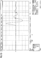
- Fig. 17 the waveform of a free, damped oscillation of an antenna coil 20 is shown, which has a conductor break.
- the natural resonant frequency of the coil, ie the interrupted coil sections, is still recognizable. These are compared to the intact coil (see. Fig. 15 . Fig. 16 ) clearly increased.
- That the two mainly occurring errors of an antenna coil 20 to be tested, a conductor break or a short circuit between coil turns, can be reliably detected by detecting and evaluating a free, damped oscillation of the antenna coil occurring as a result of the excitation of the coil 20 by an impulse.
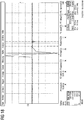
- the Fig. 19 and 20 show the swing-out behavior of an unpopulated antenna coil 20, ie an open antenna coil 20 without connected integrated circuit 30 in response to the excitation by a Dirac pulse.
- the natural resonance frequency varies.
- the natural resonance frequency is about 23 MHz, with a single-layer structure (see. Fig. 20 ), at about 43 MHz.
- Fig. 21 shown waveform shows virtually no decay more. This is substantially prevented as described by bridging the open coil. It can be concluded from this that the antenna coil tested has no conductor break, not even near one of the ends of the originally open antenna coil 20.
Landscapes
- Engineering & Computer Science (AREA)
- Computer Networks & Wireless Communication (AREA)
- Signal Processing (AREA)
- Physics & Mathematics (AREA)
- Electromagnetism (AREA)
- Near-Field Transmission Systems (AREA)
- Credit Cards Or The Like (AREA)
Priority Applications (1)
| Application Number | Priority Date | Filing Date | Title |
|---|---|---|---|
| PL12006295T PL2581984T3 (pl) | 2011-09-08 | 2012-09-06 | Sposób badania cewki antenowej |
Applications Claiming Priority (1)
| Application Number | Priority Date | Filing Date | Title |
|---|---|---|---|
| DE102011112902A DE102011112902A1 (de) | 2011-09-08 | 2011-09-08 | Verfahren zum Prüfen einer Antennenspule |
Publications (3)
| Publication Number | Publication Date |
|---|---|
| EP2581984A2 EP2581984A2 (de) | 2013-04-17 |
| EP2581984A3 EP2581984A3 (de) | 2017-08-16 |
| EP2581984B1 true EP2581984B1 (de) | 2018-11-14 |
Family
ID=46939437
Family Applications (1)
| Application Number | Title | Priority Date | Filing Date |
|---|---|---|---|
| EP12006295.5A Active EP2581984B1 (de) | 2011-09-08 | 2012-09-06 | Verfahren zum Prüfen einer Antennenspule |
Country Status (4)
| Country | Link |
|---|---|
| EP (1) | EP2581984B1 (pl) |
| DE (1) | DE102011112902A1 (pl) |
| ES (1) | ES2703125T3 (pl) |
| PL (1) | PL2581984T3 (pl) |
Families Citing this family (4)
| Publication number | Priority date | Publication date | Assignee | Title |
|---|---|---|---|---|
| DE102013002138A1 (de) * | 2013-02-07 | 2014-08-07 | Giesecke & Devrient Gmbh | Verfahren und Vorrichtung zum Prüfen eines Schaltkreises eines Endgeräts |
| JP6347607B2 (ja) * | 2013-12-27 | 2018-06-27 | キヤノン株式会社 | 電子機器 |
| DE102015013076A1 (de) | 2015-10-08 | 2017-04-13 | Giesecke & Devrient Gmbh | Prüfanlage und Prüfverfahren |
| CN111865445B (zh) * | 2020-06-17 | 2022-04-08 | 浙江大华技术股份有限公司 | 无线网桥的校准方法 |
Family Cites Families (6)
| Publication number | Priority date | Publication date | Assignee | Title |
|---|---|---|---|---|
| US2887650A (en) * | 1955-05-04 | 1959-05-19 | Newmont Mining Corp | Method of and apparatus for geophysical exploration |
| US3659197A (en) * | 1970-05-11 | 1972-04-25 | Gen Electric | Apparatus for electrically testing a coil including a primary coil and core, a pick-up coil, and limited supply of high voltage d.c. for energizing the primary coil |
| FR2771183B1 (fr) * | 1997-11-18 | 2000-01-28 | Sgs Thomson Microelectronics | Procede de test d'un circuit resonant inductif |
| DE10120625A1 (de) * | 2001-04-26 | 2002-11-14 | Muehlbauer Ag | Verfahren und Vorrichtung zum kontaktlosen Testen unbestückter Antennen |
| DE102009011821A1 (de) * | 2009-03-05 | 2010-09-09 | Giesecke & Devrient Gmbh | Tragbarer Datenträger |
| DE102011004674A1 (de) * | 2010-02-26 | 2011-09-01 | Frank Industrie Gmbh | Klebefolie zur Deaktivierung eines passiven RFID-Transponders |
-
2011
- 2011-09-08 DE DE102011112902A patent/DE102011112902A1/de not_active Withdrawn
-
2012
- 2012-09-06 EP EP12006295.5A patent/EP2581984B1/de active Active
- 2012-09-06 ES ES12006295T patent/ES2703125T3/es active Active
- 2012-09-06 PL PL12006295T patent/PL2581984T3/pl unknown
Non-Patent Citations (1)
| Title |
|---|
| None * |
Also Published As
| Publication number | Publication date |
|---|---|
| PL2581984T3 (pl) | 2019-03-29 |
| DE102011112902A1 (de) | 2013-03-14 |
| ES2703125T3 (es) | 2019-03-07 |
| EP2581984A2 (de) | 2013-04-17 |
| EP2581984A3 (de) | 2017-08-16 |
Similar Documents
| Publication | Publication Date | Title |
|---|---|---|
| EP2754086B1 (de) | Verfahren zum prüfen einer antennenspule | |
| EP2954338B1 (de) | Verfahren und vorrichtung zum prüfen eines schaltkreises | |
| DE10232398A1 (de) | Verfahren und Vorrichtung zur Inspektion von Leiterplatten | |
| DE3235114A1 (de) | Muenzpruefgeraet | |
| EP2581984B1 (de) | Verfahren zum Prüfen einer Antennenspule | |
| DE69801800T2 (de) | Verfahren zum Prüfen einer induktiven Resonanzschaltung | |
| EP1381874B1 (de) | Verfahren und vorrichtung zum kontaktlosen testen unbestückter antennen | |
| EP2779031B1 (de) | Messverfahren und Messvorrichtung | |
| EP2815387B1 (de) | Verfahren und vorrichtung zum kontaktlosen prüfen eines flächigen sicherheitsdokuments | |
| DE212009000026U1 (de) | Verbindungssensor zur Identifikation einer Anschlussstelle in einer Schalttafel | |
| DE102008004772B4 (de) | Mehrschichtiges Folienelement und Verfahren zum Testen von Durchkontaktierungen | |
| EP2779030B1 (de) | Spuleninduktivität | |
| EP2722794A2 (de) | Prüfen eines Schaltkreises | |
| EP2765432A2 (de) | Verfahren und Vorrichtung zum Prüfen eines Schaltkreises eines Endgeräts | |
| DE102013002139A1 (de) | Verfahren und Vorrichtung zum Prüfen eines Schaltkreises | |
| EP0513952B1 (de) | Schaltung zur Störungserfassung für eine elektronische Baugruppe | |
| DE4402230C1 (de) | Verfahren zum Testen, ob Anschlußstifte einer integrierten Schaltung in eine gedruckte Schaltung elektrisch leitend eingelötet sind und Schaltungsanordnung zur Durchführung des Verfahrens | |
| DE69805039T2 (de) | Verfahren und System zum Testen eines kontaktlos arbeitenden integrierten Schaltkreises und einer Eingangskapazität eines solchen integrierten Schaltkreises | |
| WO2016150877A1 (de) | Verfahren und system zur fälschungssicherung | |
| EP1033571B1 (de) | Wirbelstromsonde | |
| DE102013002140A1 (de) | Verfahren und Vorrichtung zum Bestimmen einer Schaltkreiseigenschaft | |
| DE102013003693A1 (de) | Verfahren und Vorrichtung zum Prüfen einer Mehrzahl von Antennen | |
| DE102013002136A1 (de) | Verfahren und Vorrichtung zum Prüfen eines Datenträgers | |
| EP4125215A1 (de) | Elektrischer schaltkreis, insbesondere für einen induktiv betriebenen näherungsschalter | |
| EP4075155A1 (de) | Verfahren und messgerät zur materialprüfung eines kartenförmigen datenträgers |
Legal Events
| Date | Code | Title | Description |
|---|---|---|---|
| PUAI | Public reference made under article 153(3) epc to a published international application that has entered the european phase |
Free format text: ORIGINAL CODE: 0009012 |
|
| AK | Designated contracting states |
Kind code of ref document: A2 Designated state(s): AL AT BE BG CH CY CZ DE DK EE ES FI FR GB GR HR HU IE IS IT LI LT LU LV MC MK MT NL NO PL PT RO RS SE SI SK SM TR |
|
| AX | Request for extension of the european patent |
Extension state: BA ME |
|
| RIC1 | Information provided on ipc code assigned before grant |
Ipc: H01Q 1/22 20060101ALI20170420BHEP Ipc: H04B 5/00 20060101ALI20170420BHEP Ipc: H01Q 7/00 20060101ALI20170420BHEP Ipc: H01Q 1/38 20060101AFI20170420BHEP |
|
| PUAL | Search report despatched |
Free format text: ORIGINAL CODE: 0009013 |
|
| AK | Designated contracting states |
Kind code of ref document: A3 Designated state(s): AL AT BE BG CH CY CZ DE DK EE ES FI FR GB GR HR HU IE IS IT LI LT LU LV MC MK MT NL NO PL PT RO RS SE SI SK SM TR |
|
| AX | Request for extension of the european patent |
Extension state: BA ME |
|
| RAP1 | Party data changed (applicant data changed or rights of an application transferred) |
Owner name: GIESECKE+DEVRIENT MOBILE SECURITY GMBH |
|
| RIC1 | Information provided on ipc code assigned before grant |
Ipc: H04B 5/00 20060101ALI20170712BHEP Ipc: H01Q 1/22 20060101ALI20170712BHEP Ipc: H01Q 7/00 20060101ALI20170712BHEP Ipc: H01Q 1/38 20060101AFI20170712BHEP |
|
| STAA | Information on the status of an ep patent application or granted ep patent |
Free format text: STATUS: REQUEST FOR EXAMINATION WAS MADE |
|
| 17P | Request for examination filed |
Effective date: 20180216 |
|
| RBV | Designated contracting states (corrected) |
Designated state(s): AL AT BE BG CH CY CZ DE DK EE ES FI FR GB GR HR HU IE IS IT LI LT LU LV MC MK MT NL NO PL PT RO RS SE SI SK SM TR |
|
| GRAP | Despatch of communication of intention to grant a patent |
Free format text: ORIGINAL CODE: EPIDOSNIGR1 |
|
| STAA | Information on the status of an ep patent application or granted ep patent |
Free format text: STATUS: GRANT OF PATENT IS INTENDED |
|
| RIC1 | Information provided on ipc code assigned before grant |
Ipc: H04B 5/00 20060101ALI20180322BHEP Ipc: H01Q 1/22 20060101ALI20180322BHEP Ipc: H04B 17/12 20150101ALI20180322BHEP Ipc: H01Q 7/00 20060101ALI20180322BHEP Ipc: H01Q 1/38 20060101AFI20180322BHEP |
|
| INTG | Intention to grant announced |
Effective date: 20180406 |
|
| GRAS | Grant fee paid |
Free format text: ORIGINAL CODE: EPIDOSNIGR3 |
|
| GRAA | (expected) grant |
Free format text: ORIGINAL CODE: 0009210 |
|
| STAA | Information on the status of an ep patent application or granted ep patent |
Free format text: STATUS: THE PATENT HAS BEEN GRANTED |
|
| AK | Designated contracting states |
Kind code of ref document: B1 Designated state(s): AL AT BE BG CH CY CZ DE DK EE ES FI FR GB GR HR HU IE IS IT LI LT LU LV MC MK MT NL NO PL PT RO RS SE SI SK SM TR |
|
| REG | Reference to a national code |
Ref country code: GB Ref legal event code: FG4D Free format text: NOT ENGLISH |
|
| REG | Reference to a national code |
Ref country code: CH Ref legal event code: EP Ref country code: AT Ref legal event code: REF Ref document number: 1065930 Country of ref document: AT Kind code of ref document: T Effective date: 20181115 |
|
| REG | Reference to a national code |
Ref country code: DE Ref legal event code: R096 Ref document number: 502012013801 Country of ref document: DE |
|
| REG | Reference to a national code |
Ref country code: IE Ref legal event code: FG4D Free format text: LANGUAGE OF EP DOCUMENT: GERMAN |
|
| REG | Reference to a national code |
Ref country code: ES Ref legal event code: FG2A Ref document number: 2703125 Country of ref document: ES Kind code of ref document: T3 Effective date: 20190307 |
|
| REG | Reference to a national code |
Ref country code: NL Ref legal event code: MP Effective date: 20181114 |
|
| REG | Reference to a national code |
Ref country code: LT Ref legal event code: MG4D |
|
| PG25 | Lapsed in a contracting state [announced via postgrant information from national office to epo] |
Ref country code: BG Free format text: LAPSE BECAUSE OF FAILURE TO SUBMIT A TRANSLATION OF THE DESCRIPTION OR TO PAY THE FEE WITHIN THE PRESCRIBED TIME-LIMIT Effective date: 20190214 Ref country code: LT Free format text: LAPSE BECAUSE OF FAILURE TO SUBMIT A TRANSLATION OF THE DESCRIPTION OR TO PAY THE FEE WITHIN THE PRESCRIBED TIME-LIMIT Effective date: 20181114 Ref country code: HR Free format text: LAPSE BECAUSE OF FAILURE TO SUBMIT A TRANSLATION OF THE DESCRIPTION OR TO PAY THE FEE WITHIN THE PRESCRIBED TIME-LIMIT Effective date: 20181114 Ref country code: IS Free format text: LAPSE BECAUSE OF FAILURE TO SUBMIT A TRANSLATION OF THE DESCRIPTION OR TO PAY THE FEE WITHIN THE PRESCRIBED TIME-LIMIT Effective date: 20190314 Ref country code: NO Free format text: LAPSE BECAUSE OF FAILURE TO SUBMIT A TRANSLATION OF THE DESCRIPTION OR TO PAY THE FEE WITHIN THE PRESCRIBED TIME-LIMIT Effective date: 20190214 Ref country code: LV Free format text: LAPSE BECAUSE OF FAILURE TO SUBMIT A TRANSLATION OF THE DESCRIPTION OR TO PAY THE FEE WITHIN THE PRESCRIBED TIME-LIMIT Effective date: 20181114 |
|
| PG25 | Lapsed in a contracting state [announced via postgrant information from national office to epo] |
Ref country code: AL Free format text: LAPSE BECAUSE OF FAILURE TO SUBMIT A TRANSLATION OF THE DESCRIPTION OR TO PAY THE FEE WITHIN THE PRESCRIBED TIME-LIMIT Effective date: 20181114 Ref country code: SE Free format text: LAPSE BECAUSE OF FAILURE TO SUBMIT A TRANSLATION OF THE DESCRIPTION OR TO PAY THE FEE WITHIN THE PRESCRIBED TIME-LIMIT Effective date: 20181114 Ref country code: NL Free format text: LAPSE BECAUSE OF FAILURE TO SUBMIT A TRANSLATION OF THE DESCRIPTION OR TO PAY THE FEE WITHIN THE PRESCRIBED TIME-LIMIT Effective date: 20181114 Ref country code: RS Free format text: LAPSE BECAUSE OF FAILURE TO SUBMIT A TRANSLATION OF THE DESCRIPTION OR TO PAY THE FEE WITHIN THE PRESCRIBED TIME-LIMIT Effective date: 20181114 Ref country code: GR Free format text: LAPSE BECAUSE OF FAILURE TO SUBMIT A TRANSLATION OF THE DESCRIPTION OR TO PAY THE FEE WITHIN THE PRESCRIBED TIME-LIMIT Effective date: 20190215 Ref country code: PT Free format text: LAPSE BECAUSE OF FAILURE TO SUBMIT A TRANSLATION OF THE DESCRIPTION OR TO PAY THE FEE WITHIN THE PRESCRIBED TIME-LIMIT Effective date: 20190314 |
|
| PG25 | Lapsed in a contracting state [announced via postgrant information from national office to epo] |
Ref country code: IT Free format text: LAPSE BECAUSE OF FAILURE TO SUBMIT A TRANSLATION OF THE DESCRIPTION OR TO PAY THE FEE WITHIN THE PRESCRIBED TIME-LIMIT Effective date: 20181114 Ref country code: DK Free format text: LAPSE BECAUSE OF FAILURE TO SUBMIT A TRANSLATION OF THE DESCRIPTION OR TO PAY THE FEE WITHIN THE PRESCRIBED TIME-LIMIT Effective date: 20181114 Ref country code: CZ Free format text: LAPSE BECAUSE OF FAILURE TO SUBMIT A TRANSLATION OF THE DESCRIPTION OR TO PAY THE FEE WITHIN THE PRESCRIBED TIME-LIMIT Effective date: 20181114 |
|
| REG | Reference to a national code |
Ref country code: DE Ref legal event code: R097 Ref document number: 502012013801 Country of ref document: DE |
|
| PG25 | Lapsed in a contracting state [announced via postgrant information from national office to epo] |
Ref country code: RO Free format text: LAPSE BECAUSE OF FAILURE TO SUBMIT A TRANSLATION OF THE DESCRIPTION OR TO PAY THE FEE WITHIN THE PRESCRIBED TIME-LIMIT Effective date: 20181114 Ref country code: EE Free format text: LAPSE BECAUSE OF FAILURE TO SUBMIT A TRANSLATION OF THE DESCRIPTION OR TO PAY THE FEE WITHIN THE PRESCRIBED TIME-LIMIT Effective date: 20181114 Ref country code: SM Free format text: LAPSE BECAUSE OF FAILURE TO SUBMIT A TRANSLATION OF THE DESCRIPTION OR TO PAY THE FEE WITHIN THE PRESCRIBED TIME-LIMIT Effective date: 20181114 |
|
| PLBE | No opposition filed within time limit |
Free format text: ORIGINAL CODE: 0009261 |
|
| STAA | Information on the status of an ep patent application or granted ep patent |
Free format text: STATUS: NO OPPOSITION FILED WITHIN TIME LIMIT |
|
| 26N | No opposition filed |
Effective date: 20190815 |
|
| PG25 | Lapsed in a contracting state [announced via postgrant information from national office to epo] |
Ref country code: SI Free format text: LAPSE BECAUSE OF FAILURE TO SUBMIT A TRANSLATION OF THE DESCRIPTION OR TO PAY THE FEE WITHIN THE PRESCRIBED TIME-LIMIT Effective date: 20181114 |
|
| PG25 | Lapsed in a contracting state [announced via postgrant information from national office to epo] |
Ref country code: TR Free format text: LAPSE BECAUSE OF FAILURE TO SUBMIT A TRANSLATION OF THE DESCRIPTION OR TO PAY THE FEE WITHIN THE PRESCRIBED TIME-LIMIT Effective date: 20181114 |
|
| PG25 | Lapsed in a contracting state [announced via postgrant information from national office to epo] |
Ref country code: MC Free format text: LAPSE BECAUSE OF FAILURE TO SUBMIT A TRANSLATION OF THE DESCRIPTION OR TO PAY THE FEE WITHIN THE PRESCRIBED TIME-LIMIT Effective date: 20181114 |
|
| REG | Reference to a national code |
Ref country code: CH Ref legal event code: PL |
|
| PG25 | Lapsed in a contracting state [announced via postgrant information from national office to epo] |
Ref country code: LI Free format text: LAPSE BECAUSE OF NON-PAYMENT OF DUE FEES Effective date: 20190930 Ref country code: LU Free format text: LAPSE BECAUSE OF NON-PAYMENT OF DUE FEES Effective date: 20190906 Ref country code: CH Free format text: LAPSE BECAUSE OF NON-PAYMENT OF DUE FEES Effective date: 20190930 |
|
| REG | Reference to a national code |
Ref country code: BE Ref legal event code: MM Effective date: 20190930 |
|
| PG25 | Lapsed in a contracting state [announced via postgrant information from national office to epo] |
Ref country code: BE Free format text: LAPSE BECAUSE OF NON-PAYMENT OF DUE FEES Effective date: 20190930 |
|
| GBPC | Gb: european patent ceased through non-payment of renewal fee |
Effective date: 20190906 |
|
| PG25 | Lapsed in a contracting state [announced via postgrant information from national office to epo] |
Ref country code: GB Free format text: LAPSE BECAUSE OF NON-PAYMENT OF DUE FEES Effective date: 20190906 |
|
| REG | Reference to a national code |
Ref country code: AT Ref legal event code: MM01 Ref document number: 1065930 Country of ref document: AT Kind code of ref document: T Effective date: 20190906 |
|
| PG25 | Lapsed in a contracting state [announced via postgrant information from national office to epo] |
Ref country code: AT Free format text: LAPSE BECAUSE OF NON-PAYMENT OF DUE FEES Effective date: 20190906 |
|
| PG25 | Lapsed in a contracting state [announced via postgrant information from national office to epo] |
Ref country code: CY Free format text: LAPSE BECAUSE OF FAILURE TO SUBMIT A TRANSLATION OF THE DESCRIPTION OR TO PAY THE FEE WITHIN THE PRESCRIBED TIME-LIMIT Effective date: 20181114 |
|
| PG25 | Lapsed in a contracting state [announced via postgrant information from national office to epo] |
Ref country code: MT Free format text: LAPSE BECAUSE OF FAILURE TO SUBMIT A TRANSLATION OF THE DESCRIPTION OR TO PAY THE FEE WITHIN THE PRESCRIBED TIME-LIMIT Effective date: 20181114 Ref country code: HU Free format text: LAPSE BECAUSE OF FAILURE TO SUBMIT A TRANSLATION OF THE DESCRIPTION OR TO PAY THE FEE WITHIN THE PRESCRIBED TIME-LIMIT; INVALID AB INITIO Effective date: 20120906 |
|
| PG25 | Lapsed in a contracting state [announced via postgrant information from national office to epo] |
Ref country code: MK Free format text: LAPSE BECAUSE OF FAILURE TO SUBMIT A TRANSLATION OF THE DESCRIPTION OR TO PAY THE FEE WITHIN THE PRESCRIBED TIME-LIMIT Effective date: 20181114 |
|
| P01 | Opt-out of the competence of the unified patent court (upc) registered |
Effective date: 20230520 |
|
| REG | Reference to a national code |
Ref country code: DE Ref legal event code: R081 Ref document number: 502012013801 Country of ref document: DE Owner name: GIESECKE+DEVRIENT EPAYMENTS GMBH, DE Free format text: FORMER OWNER: GIESECKE+DEVRIENT MOBILE SECURITY GMBH, 81677 MUENCHEN, DE |
|
| PGFP | Annual fee paid to national office [announced via postgrant information from national office to epo] |
Ref country code: IE Payment date: 20230918 Year of fee payment: 12 Ref country code: FI Payment date: 20230918 Year of fee payment: 12 |
|
| PGFP | Annual fee paid to national office [announced via postgrant information from national office to epo] |
Ref country code: SK Payment date: 20230905 Year of fee payment: 12 Ref country code: PL Payment date: 20230828 Year of fee payment: 12 Ref country code: FR Payment date: 20230919 Year of fee payment: 12 Ref country code: DE Payment date: 20230930 Year of fee payment: 12 |
|
| PGFP | Annual fee paid to national office [announced via postgrant information from national office to epo] |
Ref country code: ES Payment date: 20231019 Year of fee payment: 12 |