EP2581984B1 - Method for testing an antenna coil - Google Patents
Method for testing an antenna coil Download PDFInfo
- Publication number
- EP2581984B1 EP2581984B1 EP12006295.5A EP12006295A EP2581984B1 EP 2581984 B1 EP2581984 B1 EP 2581984B1 EP 12006295 A EP12006295 A EP 12006295A EP 2581984 B1 EP2581984 B1 EP 2581984B1
- Authority
- EP
- European Patent Office
- Prior art keywords
- antenna coil
- coil
- open
- antenna
- closed
- Prior art date
- Legal status (The legal status is an assumption and is not a legal conclusion. Google has not performed a legal analysis and makes no representation as to the accuracy of the status listed.)
- Active
Links
- 238000000034 method Methods 0.000 title claims description 34
- 238000012360 testing method Methods 0.000 title description 43
- 230000010355 oscillation Effects 0.000 claims description 34
- 239000004020 conductor Substances 0.000 claims description 28
- 230000005284 excitation Effects 0.000 claims description 25
- 239000012876 carrier material Substances 0.000 claims description 15
- 238000010998 test method Methods 0.000 description 23
- 238000004519 manufacturing process Methods 0.000 description 15
- 238000005259 measurement Methods 0.000 description 11
- 239000010410 layer Substances 0.000 description 8
- 238000011156 evaluation Methods 0.000 description 7
- 230000004907 flux Effects 0.000 description 5
- 239000011888 foil Substances 0.000 description 5
- 229910052751 metal Inorganic materials 0.000 description 5
- 239000002184 metal Substances 0.000 description 5
- 230000002238 attenuated effect Effects 0.000 description 4
- 230000007547 defect Effects 0.000 description 4
- 239000002356 single layer Substances 0.000 description 3
- 239000000758 substrate Substances 0.000 description 3
- 238000004804 winding Methods 0.000 description 3
- 241000084490 Esenbeckia delta Species 0.000 description 2
- 230000003466 anti-cipated effect Effects 0.000 description 2
- 239000000969 carrier Substances 0.000 description 2
- 230000007812 deficiency Effects 0.000 description 2
- 230000001419 dependent effect Effects 0.000 description 2
- 238000003780 insertion Methods 0.000 description 2
- 230000037431 insertion Effects 0.000 description 2
- 238000007790 scraping Methods 0.000 description 2
- 230000035939 shock Effects 0.000 description 2
- BQCADISMDOOEFD-UHFFFAOYSA-N Silver Chemical compound [Ag] BQCADISMDOOEFD-UHFFFAOYSA-N 0.000 description 1
- 239000002313 adhesive film Substances 0.000 description 1
- 238000013459 approach Methods 0.000 description 1
- 230000005540 biological transmission Effects 0.000 description 1
- 230000015572 biosynthetic process Effects 0.000 description 1
- 238000004891 communication Methods 0.000 description 1
- 230000002950 deficient Effects 0.000 description 1
- 238000001514 detection method Methods 0.000 description 1
- 238000011161 development Methods 0.000 description 1
- 230000018109 developmental process Effects 0.000 description 1
- 238000005516 engineering process Methods 0.000 description 1
- 230000002452 interceptive effect Effects 0.000 description 1
- 239000000463 material Substances 0.000 description 1
- 239000012811 non-conductive material Substances 0.000 description 1
- 230000003071 parasitic effect Effects 0.000 description 1
- 230000000704 physical effect Effects 0.000 description 1
- 238000007639 printing Methods 0.000 description 1
- 238000004080 punching Methods 0.000 description 1
- 239000000523 sample Substances 0.000 description 1
- 229910052709 silver Inorganic materials 0.000 description 1
- 239000004332 silver Substances 0.000 description 1
- 239000011343 solid material Substances 0.000 description 1
- 230000001052 transient effect Effects 0.000 description 1
Images


Classifications
-
- H—ELECTRICITY
- H01—ELECTRIC ELEMENTS
- H01Q—ANTENNAS, i.e. RADIO AERIALS
- H01Q7/00—Loop antennas with a substantially uniform current distribution around the loop and having a directional radiation pattern in a plane perpendicular to the plane of the loop
-
- H—ELECTRICITY
- H01—ELECTRIC ELEMENTS
- H01Q—ANTENNAS, i.e. RADIO AERIALS
- H01Q1/00—Details of, or arrangements associated with, antennas
- H01Q1/12—Supports; Mounting means
- H01Q1/22—Supports; Mounting means by structural association with other equipment or articles
- H01Q1/2208—Supports; Mounting means by structural association with other equipment or articles associated with components used in interrogation type services, i.e. in systems for information exchange between an interrogator/reader and a tag/transponder, e.g. in Radio Frequency Identification [RFID] systems
-
- H—ELECTRICITY
- H01—ELECTRIC ELEMENTS
- H01Q—ANTENNAS, i.e. RADIO AERIALS
- H01Q1/00—Details of, or arrangements associated with, antennas
- H01Q1/36—Structural form of radiating elements, e.g. cone, spiral, umbrella; Particular materials used therewith
- H01Q1/38—Structural form of radiating elements, e.g. cone, spiral, umbrella; Particular materials used therewith formed by a conductive layer on an insulating support
-
- H—ELECTRICITY
- H04—ELECTRIC COMMUNICATION TECHNIQUE
- H04B—TRANSMISSION
- H04B17/00—Monitoring; Testing
- H04B17/10—Monitoring; Testing of transmitters
- H04B17/11—Monitoring; Testing of transmitters for calibration
- H04B17/12—Monitoring; Testing of transmitters for calibration of transmit antennas, e.g. of the amplitude or phase
-
- H04B5/26—
-
- H04B5/43—
Definitions
- the present invention relates to a method for testing the operability of an antenna coil for a portable data carrier.
- Portable data carriers such as a personal ID card, passport, credit card, retail security label or the like may be equipped with an antenna coil for contactless data communication with a reader.
- the antenna coil is usually connected to an integrated circuit of the data carrier, in particular a chip, and applied to a carrier or inlay layer, for example of a plastic material such as PC or PVC, a data carrier body of the data carrier, for example, printed.
- the resonant frequency of the antenna coil and its quality can be determined contactless.
- a phase and impedance analyzer is usually used.
- Such a very complex process is detailed, for example, in " RFID Handbook "by Klaus Finkenzeller, 5th edition, Carl Hanser Verlag, Kunststoff, 2008, in chapter 4.1.11.2 , described. If the measured resonance frequency is within a predetermined range, then the antenna coil is functional. This type of test is more meaningful than a purely ohmic measurement, but much more complex and best done manually. The duration of such a test is in the range of several seconds. Therefore, this test is usually not carried out during production, but only on a few samples and for production release.
- Object of the present invention is therefore to propose a method for reliable functional testing of an antenna coil without connected integrated circuit. Desirably This test is still fast, easy to perform and cost effective.
- the invention is based on the idea of closing an antenna coil without connected integrated circuit, which as a rule is present as an open antenna coil, by means of a contacting short-circuit bridge before contactless testing and subsequently testing the closed antenna coil. In this way, as explained in detail below, reliably detect errors of the antenna coil, especially those which are very close to the ends of a formerly open antenna coil.
- a method for testing the functionality of an antenna coil for a contactlessly communicating portable data carrier comprises the following steps: In a first step, the functionality of a closed antenna coil is tested contactless. If the antenna coil under test is originally present as an open antenna coil, the antenna coil is shorted in a suitable manner, described in detail below, prior to the step of testing. But it is also possible that the antenna coil already made in the production as a closed coil, for example, printed, is. In this case, an area for later interrupting the closed coil can be provided, in which then, for example, an integrated circuit can be used and connected to the then open antenna coil.
- the step of testing itself can then be carried out with a known contactless test method explained, for example, in the introduction to the description, that is to say by measuring the impedance of the antenna coil, a determination of the resonant frequency or the quality of the antenna coil.
- the method according to the invention makes it possible in a simple manner to detect faults, in particular line breaks, in an antenna coil, in particular those faults which occur very close to the contacting ends of an antenna coil. Namely, if an open antenna coil is tested with a conventional contactless test method, such a method recognizes the error described in principle or hardly, since the physical properties of a conductor portion of such a faulty, open antenna coil, if the conductor track part is large enough, hardly from the physical Characteristics of an intact coil are distinguished, since the corresponding line lengths are not sufficiently different from each other.
- this new contactless test method comprises the following sub-steps:
- a first sub-step the antenna coil is excited to vibrate.
- a pulsed magnetic field which can be generated, for example, in a simple manner by a single (DC) current pulse.
- the excitation consists of a single magnetic field pulse.
- the DC pulse can be generated as a Dirac shock.
- the magnetic field is generated by a (DC) current pulse, which - unlike a Dirac shock - only has a steep edge.
- the exciting of the antenna coil is effected contactlessly via an excitation coil, which is coupled thereto with a corresponding pulse generator.
- the free, damped oscillation of the antenna coil which is generated in response to the excitation, is detected. This is preferably also done without contact by means of a measuring antenna. Excitation coil and measuring antenna are preferably arranged in the immediate vicinity of the antenna coil to be tested.
- the detected free, damped oscillation of the antenna coil is evaluated. This can be done by means of a suitable evaluation device, which is connected to the measuring antenna.
- the evaluation device can in particular use a comparison with reference values of an intact antenna coil.
- a digital signal processor (DSP) or an oscilloscope can be used in a known manner, for example.
- a (t) may correspond to the current I or the voltage U of an electrical resonant circuit formed by the antenna coil.
- the angular frequency ⁇ corresponds to the natural resonance frequency of the antenna coil. From the decay coefficient ⁇ , the quality of the antenna coil can be determined. The longer the decay process lasts, the higher the quality of the corresponding resonant circuit. That an evaluation of the free attenuated oscillation of the antenna coil, d. H. their decay immediately after the excitation, it allows to determine both the natural frequency and the quality of the antenna coil.
- the applicability of the contactless test method is based on the fact that a defect of the antenna coil to be tested, such as an interruption of a conductor track or a short circuit between individual coil windings of the antenna coil, leads to a noticeable in a test described waveform of the swinging significantly from a different waveform of the swinging out of an intact antenna coil. Based on the evaluated free, damped vibration detected parameters of a faulty Coil, in particular their natural resonance frequency and their quality, differ significantly from the corresponding parameters of an intact antenna coil.
- a conductor break for example, is reflected in a clearly recognizable changed decay behavior, in particular an altered, usually increased natural resonant frequency. In the case of a short circuit of two or more coil turns barring is no longer observed.
- the advantages of the contactless testing method are obvious and numerous.
- the examination of the antenna coil can be carried out without contact, with a very short time and thus in particular during an ongoing production process.
- even a printed antenna coil, which has not yet completely cured can be tested with the method according to the invention.
- the required testing device is comparatively easy and inexpensive to provide.
- the method not only allows to detect errors or deficiencies of a defective antenna coil, but also to distinguish different types of errors.
- the method also allows with an unchanged structure both a testing of unpopulated antenna coils, ie those which are not yet connected to an integrated circuit, as well as antenna coils with connected circuit, such as already completed transponders or contactlessly communicating chip cards.
- the method can be carried out in parallel for a plurality of antennas, which are arranged, for example, side by side on a production sheet, without the need for shielding individual antennas.
- antenna coils can thus be tested by means of this method quickly, easily and inexpensively in terms of their functionality.
- the excitation coil and the measuring antenna for checking the antenna coil or in the test apparatus are arranged "orthogonal" to each other.
- the exciting coil and the measuring antenna are arranged not orthogonal to each other, but for example next to each other, the excitation pulse of the exciting coil is also detected by the measuring antenna.
- the Abschwing the exciter coil then superimposed on the Abschwing the antenna coil to be measured.
- the excitation coil In an "orthogonal" arrangement of the excitation coil to the measuring antenna, these are such to each other that the signal of the excitation coil is not perceived by the measuring antenna.
- the excitation coil is arranged spatially relative to the measuring antenna in such a way that substantially no signal is coupled into the measuring antenna.
- a signal is coupled into a coil whenever the ring integral across the magnetic flux ⁇ through this coil is greater than zero (see RFID Handbook, chapters 4.1.6 and 4.1.9.2 cited above).
- the integral over the magnetic flux ⁇ is zero if and only if magnetic field lines of different direction and field strength in the measuring antenna over the total area cancel each other, or if the angle of the field lines to the coil axis is exactly 90 ° - hence the term "orthogonal" arrangement.
- the antenna coil to be tested can initially be closed in the context of the test method according to the invention.
- the then emerging in the step of breaking ends of a conductor of the then open antenna coil can serve as terminals for components of an integrated circuit, in particular a chip.
- the ends of the open antenna coil can also be bridged temporarily by means of an external bridging device, preferably in the form of a roller described in detail below.
- an external bridging device preferably in the form of a roller described in detail below.
- This type of bridging is preferably used when the distance between the ends of an open antenna coil to be bridged is so small that a subsequent removal of the bridging for interrupting a conductor track of the antenna coil at the same location would be very costly due to the low tolerances.
- the manner in which the step of interrupting a trace of the antenna coil after the contactless check is actually performed depends on how the open antenna coil has been previously closed.
- the interruption usually takes place simply by removing the bridging device.
- the already only temporarily applied connection of the open ends of the antenna coil can be performed in this way without interfering with the structure of the antenna coil and / or the carrier material.
- the interruption of the conductor track of the now-tested, closed antenna coil is effected by removing a part of the closed conductor track, preferably in the region previously the shorting bridge has been arranged. This can be done in various ways, for example by punching out a corresponding region in the carrier layer, which can then serve for example for insertion of the integrated circuit. However, a portion of the trace may also be removed by laser, by mechanical "scraping", or by other suitable means.
- the step of non-contact testing of the antenna coil is carried out again with regard to its functionality after the step of interrupting the closed antenna coil. This can be done again with one of the contactless test methods described above.
- the test method newly presented in detail in the context of this invention and described in detail above, which is based on an evaluation of the transient response of the antenna coil tested is preferably used.
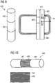
- a bridging device for temporarily bridging the ends of an open antenna coil arranged on a carrier material for a contactlessly communicating portable data carrier is characterized in that the bridging device is designed as an at least partially electrically conductive pressure roller.
- This roller is typically formed as a part of a conveyor system of an apparatus for producing the antenna coil and is arranged to bridge the ends of the open antenna coil such that a closed conductor path is formed when the carrier material is conveyed under the pressure roller.
- the radius of the pressure roller is selected such that a bearing surface of the pressure roller on the carrier material simultaneously contacts the ends of the open antenna coil when the carrier material is conveyed under the pressure roller.
- the pressure roller consists to a large extent of an electrically non-conductive material, for example Plastic. Only in a limited area, in which the ends of the open antenna coil are conveyed under the roller, an electrically conductive portion, preferably only on a surface of the roller, is provided, for example in the form of a metal foil.
- the pressure roller is formed such that the electrically conductive portion of the pressure roller coaxially on the surface of the pressure roller extending conductive segments, each of which conductive segments are separated.
- the conductive segments can be arranged for example in the form of metal foil strips on the roller. It is understood that the width of the electrically conductive strip is preferably chosen so that when an arc is conveyed through with the carrier carrying the antenna coils under the roller, at least one such strip on the substrate comes to rest such that the ends the open antenna coil are connected, ie that temporarily creates a closed antenna coil.
- FIG. 1 and 2 For example, two different inlay layers 10 of a portable data carrier, in the example of a chip card shown, with antenna coil 20 arranged thereon are shown.
- the antenna coil 20 can be applied on both sides, wherein a through-hole is then necessary to form a crossing point.
- an intersection is formed by means of a bridge (bottom right in the figure).
- the antenna coil 20 in Fig. 2 is open and still empty.
- the ends 27, 28 of the open antenna coil 20 are provided as contact points for later contacting the circuit 30.
- the natural resonance of the antenna coil 20 can be of different heights, for example in a coil with a two-layer structure at approximately 23 MHz, in a single-layer structure at approximately 43 MHz.
- an antenna coil 20 originally disclosed as open by means of a conductive shorting bridge 35 (see. Fig. 5 ), ie a closed antenna coil 20 is formed.
- a closed antenna coil 20 is formed.
- an area to be bridged 40 which in Fig. 6 is characterized as described below with reference to the Fig. 7 to 10 described in detail, be temporarily bridged by means of an external lock-up device 400.
- a contactless test now performed on the closed antenna coil 20 can reliably detect a fault of the antenna coil in the form of a conductor break even if it is present in one of the areas 50, 51 described as problematic. This is because an intact antenna coil is now closed as desired, while an antenna coil already having a conductor break, no matter where, after bridging the open contacting ends 27, 28, is still open. The distinction of an open from a closed antenna coil succeeds reliably with any of the known contactless test methods.
- the bridging 35 arranged in the manner described before the test step is removed again. That is the conductor track the closed antenna coil is interrupted.
- This step of interrupting is performed before the antenna coil is connected to components of an integrated circuit.
- the antenna coil 20 is already manufactured, for example printed, during production as a closed antenna coil.
- the bridging of the ends 27, 28 is already anticipated here in order to simplify the manufacturing process of the coil as a whole. Only now, after contactless testing of the antenna coil, is the bypass 35 removed to obtain the intended open antenna coil 20.
- Interrupting the trace of the closed antenna coil 20 by removing the bridging 35 deposited on the substrate 10 may be accomplished by known methods. For example, a punch-out can be made in the area of the bridging. On the one hand, this removes the bridging 35 and on the other hand causes a receptacle for an integrated circuit 30 to be contacted with the antenna coil 20 (cf. Fig. 1 ). But it is also possible to wegzulaser the bridging, mechanically "scraping" or remove in any other way. A bridging by an external bridging device 400 is removed by removing the bridging device 400, whereby the temporarily closed conductor track of the antenna coil 20 is interrupted and again an open antenna coil 20 is formed.
- the step of non-contact testing is repeated on the now open antenna coil.
- other types of errors of the antenna coil in particular short circuits between individual coil turns, can be reliably detected.
- an area designated 40 as described below by way of example, bridged by means of an external bridging device.
- an at least partially electrically conductive pressure roller 400 serve. This is preferably integrated in a conveyor system of an apparatus for the production of antenna coils.
- the pressure roller 400 is configured to bridge the ends 27, 28 of an open antenna coil 20 such that a closed conductor track is formed when the carrier material 10 is conveyed under the pressure roller 400, as shown in FIG Fig. 7 in side view and in the Fig. 8 and 9 is shown in plan view.
- the carrier material (cf. Fig. 8 ) is usually part of an endless sheet 420 (see. Fig. 7 ).
- the radius of the pressure roller 400 is selected so that the bearing surface 410 of the pressure roller 400 on the substrate 10 simultaneously contacts the ends 27, 28 of the open antenna coil 20, as shown in FIG Fig. 8 and 9 is indicated.
- the pressure roller 400 is usually made of plastic. In a limited area, in which the ends 27, 28 of the open antenna coil 20 are conveyed under the roller 400, the pressure roller has an electrically conductive region 450, the remaining part 440 of the roller 400 is thus usually not electrically conductive (see , Fig. 9 ).
- the conductive region 450 may be formed, for example, by means of a metal foil surrounding the roller 400.
- the electrically conductive region 450 is formed of solid material or, as described, a continuous conductive surface, such as a circumferential metal foil, there is a risk that eddy currents will be generated in the conductive surface which may be applied to the device under test, i. the antenna coil 20 to be tested, act back and falsify the measurement result regarding the functionality of the antenna coil in a mostly irreproducible way.
- the conductive region 450 designed such that arranged parallel to the roll axis conductive segments alternate with non-conductive segments.
- the conductive elements are conductive only on their surface.
- the respective segments are, as mentioned, arranged coaxially, preferably in the form of strips, on the roll surface.
- Conductive strips 450 for example of metal foil, alternate with non-conductive strips 451. In this way, eddy currents can be effectively prevented.
- the width of the strips 450 is chosen so that when passing through the arc 420 always a conductive strip in the area to be bridged open ends 27, 28 of the antenna coil 20 comes to rest and this bridged. At this time, the step of non-contact testing of the closed antenna coil 20 may be performed.
- the step of non-contact testing of the closed antenna coil 20 in the context of the method according to the invention can be carried out by means of known contactless testing methods.
- these have, as already stated in the introduction, numerous deficiencies, in particular, these methods are technically very complicated.
- a new, contactless test method is generally presented, which can advantageously be used in the step of contactless testing of the closed antenna coil 20.
- This method which is basically based on the decay behavior of an excited antenna coil 20, i. analyzing the free, damped vibration of the antenna coil 20 generated by an impulse can particularly easily distinguish an open antenna coil 20 from a closed antenna coil 20, but is not limited thereto as described in detail below.
- the basic steps of the test method are to excite the antenna coil 20 to be tested for oscillation, detect the free, damped oscillation of the antenna coil in response to the excitation and evaluate the detected oscillation.
- Fig. 11 shows the theoretical course of a free, damped oscillation A (t) over time t.
- a (t) can correspond to the current I or the voltage U.
- the angular frequency ⁇ corresponds to the natural resonance frequency of the corresponding coil, from the decay coefficient ⁇ the quality of the coil can be determined.
- Fig. 12 schematically shows the structure of a test apparatus 100 for testing an antenna coil 20 by means of the new test method.
- the device 100 comprises a pulse generator 110 with connected amplifier 120.
- the output of the amplifier 120 is applied to an exciter coil 130, which preferably has only one turn.
- a measuring antenna 140 is arranged orthogonal to the exciting coil 130.
- An amplifier 150 whose output is connected to an evaluation device 160, is again arranged on the measuring antenna 140, which preferably also has only one coil turn.
- the term "orthogonal" arrangement of two coils to each other is used so that the arrangement of the excitation coil 130 to the measuring antenna 140 spatially so that in the measuring antenna 140 as possible no signal the exciter coil is coupled.
- this is the case if and only if the ring integral over the magnetic flux ⁇ through this coil is greater than zero.
- the integral over the magnetic flux ⁇ is zero if and only if magnetic field lines of different direction and field strength in the measurement antenna 140 cancel each other over the total area, or if the angle of the field lines to the coil axis is exactly 90 °.
- the excitation coil 130 and the measuring antenna 140 are coplanarly arranged "orthogonal" to each other, as shown, partially overlapping both coils.
- This arrangement can be further tuned such that the integral over the magnetic flux gives zero as desired. This is because the magnetic field lines generated by the exciting coil 130 inside and outside the exciting coil 130 extend in different directions, respectively.
- the degree of overlap of the exciting coil 130 and the measuring antenna 140 is now selected so that these field lines in the inner surface of the measuring antenna 140 cancel each other exactly.
- an orthogonal arrangement of the exciting coil 130 to the measuring antenna 140 facilitates the detection of the swinging-out of the antenna coil 20 to be tested.
- the measuring antenna 140 is preferably designed so that it has the lowest possible quality and that the input capacitance of an optionally connected via a (coaxial) cable amplifier 150 as possible can not be effective because the measuring antenna 140 would otherwise bring a strong self-oscillation in the measurement , This would do the measurement, i. detecting the free attenuated oscillation of the antenna coil 20 to be tested. In particular, the natural oscillation would always have to be eliminated.
- the self-resonance of the measuring antenna 140 can be suppressed by using a compensation circuit (not shown). This consists of a parallel connection of a capacitance and a resistor, these variables typically being in the range of approximately 1 to 50 pF or 1 to 10 MOhm.
- the compensation circuit lies in series with the measuring antenna 140. Due to the high series resistance, the quality of the measuring antenna 140 practically approaches zero. As a result, the self-resonance is no longer effective. To calculate this compensation circuit, for example, the formulas known for calculating the compensation for oscilloscope probes can
- the antenna coil is excited by a Dirac pulse.
- the pulse generator 110 is set so that it reaches a maximum amplitude in the shortest possible time. For example, an amplitude of 12 V with a width of only 29 ns can be achieved.
- Fig. 13 is a corresponding waveform indicated.
- the pulse generator 110 is connected to the exciter coil 130, the result is - without arrangement of the antenna coil 20 - due to the resulting magnetic field resulting energy detected by the measuring antenna 140 waveform with subsequent settling time, as in Fig. 14 is illustrated.
- the antenna coil 20 to be tested is now arranged directly under the excitation coil 130, the antenna coil is excited by the positive Dirac pulse of the pulse generator 110 to a free, damped oscillation. From the resulting typical swinging of the antenna coil 20, the natural resonance frequency of the antenna coil 20 and the quality can be determined. If the antenna coil 20 has a manufacturing error, for example a conductor break or a short circuit between individual coil turns, this leads, as illustrated below, to a significantly different signal waveform of the "ringing", i. the corresponding free, damped oscillation of the damaged antenna coil. In particular, self-resonant frequency and / or quality of such a coil are clearly distinguishable from the corresponding values of an intact antenna coil.
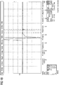
- Fig. 15 the waveform of a free, damped oscillation of an intact, open antenna coil 20 is shown.
- Fig. 16 is indicated by the arrows in the figure, as the self-resonance of the tested coil can be determined based on the detected waveform.
- the the measurement results in Fig. 15 underlying open antenna coil without a chip, for example, has a natural resonance frequency of about 45 MHz.
- a transponder ie an antenna coil with a connected integrated circuit, usually has a natural resonant frequency of the order of magnitude the transmission frequency of an associated reader.
- Contactless chip cards according to ISO / IEC 14443 are tuned at a given reading frequency of 13.56 MHz usually in the range of 15 to 17 MHz.
- An antenna coil without connected integrated circuit on a corresponding carrier material together with the parasitic capacitances occurring between the windings also forms a resonant circuit, usually with a natural resonant frequency in the range of 30 to 50 MHz, depending on the dielectric constant of the carrier material and the number of turns.
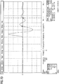
- Fig. 17 the waveform of a free, damped oscillation of an antenna coil 20 is shown, which has a conductor break.
- the natural resonant frequency of the coil, ie the interrupted coil sections, is still recognizable. These are compared to the intact coil (see. Fig. 15 . Fig. 16 ) clearly increased.
- That the two mainly occurring errors of an antenna coil 20 to be tested, a conductor break or a short circuit between coil turns, can be reliably detected by detecting and evaluating a free, damped oscillation of the antenna coil occurring as a result of the excitation of the coil 20 by an impulse.
- the Fig. 19 and 20 show the swing-out behavior of an unpopulated antenna coil 20, ie an open antenna coil 20 without connected integrated circuit 30 in response to the excitation by a Dirac pulse.
- the natural resonance frequency varies.
- the natural resonance frequency is about 23 MHz, with a single-layer structure (see. Fig. 20 ), at about 43 MHz.
- Fig. 21 shown waveform shows virtually no decay more. This is substantially prevented as described by bridging the open coil. It can be concluded from this that the antenna coil tested has no conductor break, not even near one of the ends of the originally open antenna coil 20.
Description
Die vorliegende Erfindung betrifft ein Verfahren zum Prüfen der Funktionsfähigkeit einer Antennenspule für einen portablen Datenträger.The present invention relates to a method for testing the operability of an antenna coil for a portable data carrier.
Portable Datenträger, wie beispielsweise ein Personalausweis, ein Reisepass, eine Kreditkarte, ein Label zur Warensicherung oder dergleichen, können mit einer Antennenspule zur kontaktlosen Datenkommunikation mit einem Lesegerät ausgestattet sein. Die Antennenspule ist dazu in der Regel mit einem integrierten Schaltkreis des Datenträgers, insbesondere einem Chip, verbunden und auf einer Träger- oder Inlayschicht, beispielsweise aus einem Kunststoffmaterial wie PC oder PVC, eines Datenträgerkörpers des Datenträgers aufgebracht, beispielsweise aufgedruckt.Portable data carriers such as a personal ID card, passport, credit card, retail security label or the like may be equipped with an antenna coil for contactless data communication with a reader. The antenna coil is usually connected to an integrated circuit of the data carrier, in particular a chip, and applied to a carrier or inlay layer, for example of a plastic material such as PC or PVC, a data carrier body of the data carrier, for example, printed.
Um die Funktionsfähigkeit einer Antennenspule während oder nach der Herstellung des entsprechenden Datenträgers zu prüfen, sind verschiedene Verfahren bekannt. Bei einer solchen Prüfung wird im Wesentlichen geprüft, ob die Antennenspule einen Bruch aufweist und/oder ob zwei oder mehr Spulenwindungen der Antenne versehentlich kurzgeschlossen sind. Mängel dieser Art beeinträchtigen die Funktionsfähigkeit der Antennenspule erheblich bzw. zerstören diese vollständig.In order to check the operability of an antenna coil during or after the production of the corresponding data carrier, various methods are known. In such a test, it is essentially checked whether the antenna coil has a break and / or whether two or more coil turns of the antenna are accidentally short-circuited. Defects of this type considerably impair the functionality of the antenna coil or completely destroy it.
Produktionsbegleitend erfolgt zumeist eine Prüfung der Antennenspule in Form einer Gleichstrom-Widerstandsmessung. Um eine solche ohmsche Messung korrekt und mit der erforderlichen Genauigkeit durchzuführen, ist in der Regel eine 4-Punkt-Messung erforderlich. Liegen die gemessenen Werte außerhalb eines vorgegebenen Intervalls, so kann dies auf einen Leiterbahnbruch oder einen Kurzschluss hindeuten. Mit einem solchen Verfahren kann allerdings lediglich der ohmsche Anteil der Antennenspule bestimmt werden. Eine frequenzabhängige Impedanz der Spule, bestehend aus der Induktivität der Spule, dem ohmschen Anteil sowie einem kapazitiven Anteil, welcher auch von einem Trägermaterial herrühren kann, kann auf diese Weise nicht bestimmt werden. Weiterhin ist dieses Prüfverfahren aufwendig, da eine Kontaktierung der Antennenspule erforderlich ist. Wird die Antennenspule mittels eines Druckprozesses hergestellt, beispielsweise mittels Silberleitpaste aufgedruckt, so kann es zudem vorkommen, dass die Paste bei der Widerstandsmessung noch nicht vollständig ausgehärtet ist und entsprechende Kontaktstifte, welche zur Kontaktierung verwendet werden, verunreinigt werden und anschließend gereinigt oder ausgetauscht werden müssen.In production, the antenna coil is usually tested in the form of a DC resistance measurement. In order to perform such an ohmic measurement correctly and with the required accuracy, a 4-point measurement is usually required. Are the measured values outside a given interval, this may indicate a trace break or short circuit. With such a method, however, only the ohmic portion of the antenna coil can be determined. A frequency-dependent impedance of the coil, consisting of the inductance of the coil, the ohmic component and a capacitive component, which may also result from a carrier material, can not be determined in this way. Furthermore, this test method is expensive, since a contacting of the antenna coil is required. If the antenna coil is produced by means of a printing process, for example printed by silver conductive paste, it may also happen that the paste is not completely cured in the resistance measurement and corresponding pins that are used for contacting, are contaminated and then cleaned or replaced.
Alternativ können die Resonanzfrequenz der Antennenspule und deren Güte kontaktlos bestimmt werden. Dazu wird in der Regel ein Phasen- und Impedanz-Analysator verwendet. Ein solches, sehr aufwendiges Verfahren ist detailliert beispielsweise im "
Bevorzugt wird die Antennenspule geprüft, bevor der Schaltkreis im weiteren Produktionsprozess mit der Antennenspule gekoppelt wird, um eine fehlerhafte Antennenspule bereits zu einem frühen Produktionszeitpunkt identifizieren zu können. Damit kann vermieden werden, dass fertig hergestellte Datenträger mit Schaltkreis allein wegen einer fehlerhaften Antennenspule aussortiert werden müssen.Preferably, the antenna coil is tested before the circuit is coupled in the further production process with the antenna coil in order to identify a faulty antenna coil already at an early production time can. This avoids that finished data carriers with circuit must be sorted out only because of a faulty antenna coil.
Liegt ein Fehler, insbesondere ein Leiterbahnbruch, einer solchen Antennenspule ohne angeschlossenen integrierten Schaltkreis allerdings nahe einem der Enden der Antennenspule vor, wobei diese Enden in der Regel als Anschlusskontakte für Komponenten des anzuschließenden Schaltkreises dienen, so ist die Aussagekraft der beschriebenen, kontaktlosen Prüfungen der entsprechenden Antennenspule eingeschränkt. Dies gilt, da das Ergebnis der Prüfung in der Regel die genannten Parameter des restlichen, größeren Anteils der Antennenspule abbildet. Diese gemessenen Parameter entsprechen dann aber annährend denen der gesamten, intakten Antennenspule. Somit kann ein Fehler nahe einem Ende der offenen Antennenspule mit den beschriebenen Verfahren nicht oder nur unzureichend erkannt werden.However, if there is a fault, in particular a conductor break, of such an antenna coil without connected integrated circuit near one of the ends of the antenna coil, these ends usually serve as connection contacts for components of the circuit to be connected, the validity of the described, non-contact tests of the corresponding Antenna coil restricted. This applies because the result of the test usually reflects the mentioned parameters of the remaining, larger portion of the antenna coil. However, these measured parameters then approximately correspond to those of the entire, intact antenna coil. Thus, an error near an end of the open antenna coil can not or only insufficiently be detected with the described methods.
Aus der
Aufgabe der vorliegenden Erfindung ist es demnach, ein Verfahren zur zuverlässigen Funktionsprüfung einer Antennenspule ohne angeschlossenen integrierten Schaltkreis vorzuschlagen. Wünschenswerterweise ist diese Prüfung weiterhin schnell, einfach durchzuführen und kostengünstig.Object of the present invention is therefore to propose a method for reliable functional testing of an antenna coil without connected integrated circuit. Desirably This test is still fast, easy to perform and cost effective.
Diese Aufgabe wird durch ein Verfahren mit den Merkmalen des unabhängigen Anspruchs 1 gelöst. Vorteilhafte Ausgestaltungen und Weiterbildungen der Erfindung sind in den abhängigen Ansprüchen angegeben.This object is achieved by a method having the features of
Die Erfindung basiert auf dem Grundgedanken, eine Antennenspule ohne angeschlossenen integrierten Schaltkreis, welche in der Regel als offene Antennenspule vorliegt, vor einem kontaktlosen Prüfen auf deren Funktionsfähigkeit mittels einer kontaktierenden Kurzschlussbrücke zu schließen und anschließend die geschlossene Antennenspule zu prüfen. Auf diese Weise können, wie nachstehend detailliert erläutert, zuverlässig Fehler der Antennenspule erkannt werden, insbesondere auch solche, welche sehr nahe an den Enden einer vormals offenen Antennenspule vorliegen.The invention is based on the idea of closing an antenna coil without connected integrated circuit, which as a rule is present as an open antenna coil, by means of a contacting short-circuit bridge before contactless testing and subsequently testing the closed antenna coil. In this way, as explained in detail below, reliably detect errors of the antenna coil, especially those which are very close to the ends of a formerly open antenna coil.
Demnach umfasst ein erfindungsgemäßes Verfahren zum Prüfen der Funktionsfähigkeit einer Antennenspule für einen kontaktlos kommunizierenden portablen Datenträger folgende Schritte:
In einem ersten Schritt wird die Funktionsfähigkeit einer geschlossenen Antennenspule kontaktlos geprüft. Falls die zu prüfende Antennenspule ursprünglich als offene Antennenspule vorliegt, wird die Antennenspule in geeigneter, nachstehend detailliert beschriebener Weise vor dem Schritt des Prüfens kurzgeschlossen. Es ist aber auch möglich, dass die Antennenspule bereits bei der Herstellung als geschlossene Spule hergestellt, beispielsweise gedruckt, wird. Dabei kann ein Bereich zum späteren Unterbrechen der geschlossenen Spule vorgesehen werden, in welchen dann beispielsweise ein integrierter Schaltkreis eingesetzt und an die dann offene Antennenspule angeschlossen werden kann.Accordingly, a method according to the invention for testing the functionality of an antenna coil for a contactlessly communicating portable data carrier comprises the following steps:
In a first step, the functionality of a closed antenna coil is tested contactless. If the antenna coil under test is originally present as an open antenna coil, the antenna coil is shorted in a suitable manner, described in detail below, prior to the step of testing. But it is also possible that the antenna coil already made in the production as a closed coil, for example, printed, is. In this case, an area for later interrupting the closed coil can be provided, in which then, for example, an integrated circuit can be used and connected to the then open antenna coil.
Der Schritt des Prüfens selbst kann dann mit einem bekannten, beispielsweise in der Beschreibungseinleitung erläuterten kontaktlosen Prüfverfahren durchgeführt werden, also etwa durch eine Messung der Impedanz der Antennenspule, eine Bestimmung der Resonanzfrequenz oder der Güte der Antennenspule.The step of testing itself can then be carried out with a known contactless test method explained, for example, in the introduction to the description, that is to say by measuring the impedance of the antenna coil, a determination of the resonant frequency or the quality of the antenna coil.
Wie bereits angedeutet, ermöglicht es das erfindungsgemäße Verfahren auf einfache Weise, Fehler, insbesondere Leitungsbrüche, in einer Antennenspule zu erkennen, insbesondere solche Fehler, welche sehr nahe an den Kontaktierungsenden einer Antennenspule auftreten. Wird nämlich eine offene Antennenspule mit einem herkömmlichen kontaktlosen Prüfverfahren geprüft, so erkennt ein solches Verfahren die beschriebenen Fehler prinzipbedingt nicht oder kaum, da die physikalischen Eigenschaften eines Leiterbahnteils einer derart fehlerhaften, offenen Antennenspule, wenn der Leiterbahnteil nur groß genug ist, kaum von den physikalischen Eigenschaften einer intakten Spule zu unterscheiden sind, da sich die entsprechenden Leitungslängen nicht ausreichend voneinander unterscheiden.As already indicated, the method according to the invention makes it possible in a simple manner to detect faults, in particular line breaks, in an antenna coil, in particular those faults which occur very close to the contacting ends of an antenna coil. Namely, if an open antenna coil is tested with a conventional contactless test method, such a method recognizes the error described in principle or hardly, since the physical properties of a conductor portion of such a faulty, open antenna coil, if the conductor track part is large enough, hardly from the physical Characteristics of an intact coil are distinguished, since the corresponding line lengths are not sufficiently different from each other.
Die erfindungsgemäße Vorgehensweise eines absichtlichen Kurzschließens der Antennenspule zur Bildung einer geschlossenen Antennenspule, macht es nun auf einfache Weise möglich, auch einen solchen Fehler zuverlässig zu erkennen.The procedure according to the invention of deliberately short-circuiting the antenna coil to form a closed antenna coil now makes it possible in a simple manner to reliably detect even such an error.
Lag in der ursprünglichen (offenen) Antennenspule ohne Chip ein Leiterbahnbruch vor, egal an welcher Stelle, d.h. auch nahe an einem der Kontaktierungsenden der Antennenspule, so ist die nun veränderte, d.h. durch Überbrückung der Kontaktierungsenden kurzgeschlossene Spule, immer noch offen. Sie ist klar von einer intakten Spule, welche nun aufgrund der Überbrückung geschlossen sein sollte, zu unterscheiden. Jedes der genannten Prüfverfahren kann zuverlässig eine offene Antennenspule von einer geschlossenen Antennenspule unterscheiden.If there was a conductor break in the original (open) antenna coil without a chip, no matter where, ie close to one of the contacting ends of the antenna coil, the now changed coil, ie shorted by bridging the contacting ends, is still open. It is clearly distinguishable from an intact coil, which should now be closed due to the bridging. Each of the above test methods can reliably distinguish an open antenna coil from a closed antenna coil.
Dabei ist es, wie erwähnt, möglich, auch solche Antennenspulen, für welche das spätere Verbinden mit einem integrierten Schaltkreis vorgesehen ist, welche somit als offene Antennenspulen hergestellt werden müssten, zunächst als geschlossene Antennenspule herzustellen. Der Schritt des Überbrückens wird somit vorweggenommen. Dazu kann beispielsweise ein später zu entfernender Bereich einer Leiterbahn der Antennenspule, welcher dann zum Einsetzen des integrierten Schaltkreises dient, bei der Herstellung der Antennenspule zunächst kurzgeschlossen werden.It is, as mentioned, possible, even such antenna coils, for which the subsequent connection is provided with an integrated circuit, which would thus have to be prepared as open antenna coils, first to produce a closed antenna coil. The bridging step is thus anticipated. For this purpose, for example, a later to be removed area of a conductor track of the antenna coil, which then serves for insertion of the integrated circuit, are initially short-circuited in the manufacture of the antenna coil.
Nachfolgend wird ein neues, bevorzugtes Prüfverfahren beschriebenen, welches schnell, einfach und kostengünstig durchgeführt werden kann und welches zahlreiche Vorteile gegenüber den bekannten Verfahren besitzt. Der Grundgedanke dieses neuen Prüfverfahrens besteht darin, die zu prüfende Antennenspule zur Schwingung anzuregen und die durch die Anregung erzeugte freie, gedämpfte Schwingung der Antennenspule zu erfassen und auszuwerten, um eventuelle Mängel der Antennenspule zu erkennen. Demnach umfasst dieses neue kontaktlose Prüfverfahren folgende Teilschritte:
In einen ersten Teilschritt wird die Antennenspule zur Schwingung angeregt. Dies geschieht vorzugsweise induktiv durch ein gepulstes Magnetfeld, welches z.B. in einfacher Weise durch einen einzelnen (Gleich-)Strompuls erzeugt werden kann. Vorzugsweise besteht die Anregung aus einem einzelnen Magnetfeldpuls. Der Gleichstrompuls kann dabei als Dirac-Stoß erzeugt werden. Es ist auch möglich, dass das Magnetfeld durch einen (Gleich-) Strompuls erzeugt wird, welcher - anders als ein Dirac-Stoß - lediglich eine steile Flanke aufweist. Bevorzugt erfolgt das Anregen der Antennenspule kontaktlos über eine Erregerspule, welche dazu mit einem entsprechenden Impulsgeber gekoppelt ist.Hereinafter, a new, preferred test method is described, which can be performed quickly, easily and inexpensively and which has numerous advantages over the known methods. The basic idea of this new test method is to excite the antenna coil to be tested to vibrate and to detect and evaluate the generated by the excitation free, damped oscillation of the antenna coil to detect any shortcomings of the antenna coil. Accordingly, this new contactless test method comprises the following sub-steps:
In a first sub-step, the antenna coil is excited to vibrate. This is preferably done inductively by a pulsed magnetic field, which can be generated, for example, in a simple manner by a single (DC) current pulse. Preferably, the excitation consists of a single magnetic field pulse. The DC pulse can be generated as a Dirac shock. It is also possible that the magnetic field is generated by a (DC) current pulse, which - unlike a Dirac shock - only has a steep edge. Preferably, the exciting of the antenna coil is effected contactlessly via an excitation coil, which is coupled thereto with a corresponding pulse generator.
In einem zweiten Teilschritt des kontaktlosen Prüfverfahrens wird die freie, gedämpfte Schwingung der Antennenspule, welche in Antwort auf die Anregung erzeugt wird, erfasst. Dies geschieht vorzugsweise ebenfalls kontaktlos mittels einer Messantenne. Erregerspule und Messantenne werden dazu vorzugsweise in unmittelbarer Nähe der zu prüfenden Antennenspule angeordnet.In a second sub-step of the contactless test method, the free, damped oscillation of the antenna coil, which is generated in response to the excitation, is detected. This is preferably also done without contact by means of a measuring antenna. Excitation coil and measuring antenna are preferably arranged in the immediate vicinity of the antenna coil to be tested.
In einem dritten Teilschritt wird die erfasste freie, gedämpfte Schwingung der Antennenspule ausgewertet. Dies kann mittels einer geeigneten Auswertungseinrichtung geschehen, welche mit der Messantenne verbunden ist.In a third sub-step, the detected free, damped oscillation of the antenna coil is evaluated. This can be done by means of a suitable evaluation device, which is connected to the measuring antenna.
Eine erfindungsgemäße Prüfvorrichtung zum Prüfen der Funktionsfähigkeit der Antennenspule für einen kontaktlos kommunizierenden portablen Datenträger umfasst dazu einen Impulsgeber. Dieser ist eingerichtet, die Antennenspule über eine an den Impulsgeber angeschlossene Erregerspule kontaktlos anzuregen. Weiter umfasst die Prüfvorrichtung eine Messantenne, welche eingerichtet ist, eine freie, gedämpfte Schwingung der Antennenspule kontaktlos zu erfassen. Eine Auswertungseinrichtung der Prüfvorrichtung schließlich, welche mit der Messantenne verbunden ist, ist eingerichtet, die von der Messantenne erfasste freie, gedämpfte Schwingung auszuwerten.A test device according to the invention for testing the functionality of the antenna coil for a contactlessly communicating portable data carrier comprises a pulse generator for this purpose. This is arranged to contactlessly excite the antenna coil via an excitation coil connected to the pulse generator. Furthermore, the test apparatus comprises a measuring antenna, which is set up to detect a free, damped oscillation of the antenna coil without contact. Finally, an evaluation device of the test apparatus, which is connected to the measuring antenna, is set up to evaluate the free, damped oscillation detected by the measuring antenna.
Die Auswertungseinrichtung kann dabei insbesondere einen Vergleich mit Referenzwerten einer intakten Antennenspule heranziehen. Zur Analyse der von der Messantenne beim Erfassen der freien, gedämpften Schwingung erfassten Signale kann in bekannter Weise beispielsweise ein digitaler Signalprozessor (DSP) oder ein Oszilloskop dienen.The evaluation device can in particular use a comparison with reference values of an intact antenna coil. To analyze the signals detected by the measuring antenna when detecting the free, damped oscillation, a digital signal processor (DSP) or an oscilloscope can be used in a known manner, for example.
Die in der beschriebenen Weise angeregte Antennenspule schwingt nach der Anregung unmittelbar mit einer freien, gedämpften Schwingung A(t) aus, welche mit der folgenden Formel beschrieben werden kann: ![]()
![]()
A(t) kann dabei dem Strom I oder der Spannung U eines durch die Antennenspule gebildeten elektrischen Schwingkreises entsprechen. Demnach kann der Spannungsverlauf der Antennenspule unmittelbar nach der Anregung mit der folgenden Formel beschrieben werden: ![]()
![]()
Die Kreisfrequenz ω entspricht dabei der Eigenresonanzfrequenz der Antennenspule. Aus dem Abklingkoeffizienten δ kann die Güte der Antennenspule ermittelt werden. Je länger der Abklingvorgang dauert, desto höher ist die Güte des entsprechenden Schwingkreises. D.h. eine Auswertung der freien gedämpften Schwingung der Antennenspule, d. h. deren Ausschwingen unmittelbar nach der Anregung, erlaubt es, sowohl die Eigenresonanzfrequenz als auch die Güte der Antennenspule zu bestimmen.The angular frequency ω corresponds to the natural resonance frequency of the antenna coil. From the decay coefficient δ, the quality of the antenna coil can be determined. The longer the decay process lasts, the higher the quality of the corresponding resonant circuit. That an evaluation of the free attenuated oscillation of the antenna coil, d. H. their decay immediately after the excitation, it allows to determine both the natural frequency and the quality of the antenna coil.
Die Anwendbarkeit des kontaktlosen Prüfverfahrens beruht nun auf dem Umstand, dass ein Defekt der zu prüfenden Antennenspule, wie beispielsweise eine Unterbrechung einer Leiterbahn oder ein Kurzschluss zwischen einzelnen Spulenwindungen der Antennenspule, dazu führt, dass sich ein bei einer beschriebenen Prüfung erkennbarer Signalverlauf des Ausschwingens signifikant von einem entsprechenden Signalverlauf des Ausschwingens einer intakten Antennenspule unterscheidet. Anhand der ausgewerteten freien, gedämpften Schwingung festgestellte Parameter einer fehlerhaften Spule, insbesondere deren Eigenresonanzfrequenz und deren Güte, unterscheiden sich deutlich von den entsprechenden Parametern einer intakten Antennenspule.The applicability of the contactless test method is based on the fact that a defect of the antenna coil to be tested, such as an interruption of a conductor track or a short circuit between individual coil windings of the antenna coil, leads to a noticeable in a test described waveform of the swinging significantly from a different waveform of the swinging out of an intact antenna coil. Based on the evaluated free, damped vibration detected parameters of a faulty Coil, in particular their natural resonance frequency and their quality, differ significantly from the corresponding parameters of an intact antenna coil.
Ein Leiterbahnbruch beispielsweise zeigt sich in einem deutlich erkennbar veränderten Ausschwingverhalten, insbesondere einer veränderten, in der Regel erhöhten Eigenresonanzfrequenz. Im Falle eines Kurzschlusses von zwei oder mehr Spulenwindungen ist kaum mehr ein Ausschwingen zu beobachten.A conductor break, for example, is reflected in a clearly recognizable changed decay behavior, in particular an altered, usually increased natural resonant frequency. In the case of a short circuit of two or more coil turns barring is no longer observed.
Auf diese Weise kann beim Auswerten der freien, gedämpften Schwingung durch die Prüfvorrichtung nicht nur erkannt werden, ob die Antennenspule fehlerhaft ist oder nicht, sondern es kann im Falle eines Fehlers oder Mangels auch der Typ des Fehlers bzw. die Art des Mangels festgestellt werden.In this way, when evaluating the free, damped vibration by the test apparatus, not only can it be known whether the antenna coil is faulty or not, but also the type of the fault or the type of defect can be determined in case of a fault or defect.
Die Vorteile des kontaktlosen Prüfverfahrens sind offensichtlich und zahlreich. Die Prüfung der Antennenspule kann kontaktlos, mit sehr geringem Zeitaufwand und somit insbesondere während eines laufenden Produktionsprozesses durchgeführt werden. Insbesondere kann auch bereits eine gedruckte Antennenspule, welche noch nicht vollständig ausgehärtet ist, mit dem erfindungsgemäßen Verfahren geprüft werden. Die benötigte Prüfvorrichtung ist vergleichsweise einfach und kostengünstig bereitzustellen. Zudem erlaubt das Verfahren nicht nur, Fehler oder Mängel einer defekten Antennenspule zu erkennen, sondern auch verschiedene Fehlertypen zu unterscheiden. Das Verfahren erlaubt überdies bei unverändertem Aufbau sowohl ein Prüfen von unbestückten Antennenspulen, also solchen, welche noch nicht mit einem integrierten Schaltkreis verbunden sind, als auch von Antennenspulen mit angeschlossenem Schaltkreis, wie beispielsweise bereits fertiggestellten Transpondern oder kontaktlos kommunizierenden Chipkarten. Schließlich kann das Verfahren parallel für eine Mehrzahl von Antennen, welche beispielsweise nebeneinander auf einem Fertigungsbogen angeordnet sind, durchgeführt werden, ohne dass eine Abschirmung einzelner Antennen notwendig ist. Insgesamt können Antennenspulen mittels dieses Verfahrens somit schnell, auf einfache Weise und kostengünstig hinsichtlich ihrer Funktionsfähigkeit geprüft werden.The advantages of the contactless testing method are obvious and numerous. The examination of the antenna coil can be carried out without contact, with a very short time and thus in particular during an ongoing production process. In particular, even a printed antenna coil, which has not yet completely cured, can be tested with the method according to the invention. The required testing device is comparatively easy and inexpensive to provide. In addition, the method not only allows to detect errors or deficiencies of a defective antenna coil, but also to distinguish different types of errors. The method also allows with an unchanged structure both a testing of unpopulated antenna coils, ie those which are not yet connected to an integrated circuit, as well as antenna coils with connected circuit, such as already completed transponders or contactlessly communicating chip cards. Finally, the method can be carried out in parallel for a plurality of antennas, which are arranged, for example, side by side on a production sheet, without the need for shielding individual antennas. Overall, antenna coils can thus be tested by means of this method quickly, easily and inexpensively in terms of their functionality.
Vorzugsweise werden die Erregerspule und die Messantenne zum Prüfen der Antennenspule bzw. in der Prüfvorrichtung "orthogonal" zueinander angeordnet. In dem Fall, dass die Erregerspule und die Messantenne nicht orthogonal zueinander, sondern beispielsweise nebeneinander angeordnet sind, wird der Erregungsimpuls der Erregerspule auch von der Messantenne erfasst. Zudem überlagert dann das Abschwingverhalten der Erregerspule das zu messende Abschwingverhalten der Antennenspule.Preferably, the excitation coil and the measuring antenna for checking the antenna coil or in the test apparatus are arranged "orthogonal" to each other. In the case that the exciting coil and the measuring antenna are arranged not orthogonal to each other, but for example next to each other, the excitation pulse of the exciting coil is also detected by the measuring antenna. In addition, the Abschwingverhalten the exciter coil then superimposed on the Abschwingverhalten the antenna coil to be measured.
Bei einer "orthogonalen" Anordnung der Erregerspule zu der Messantenne liegen diese derart zueinander, dass das Signal der Erregerspule von der Messantenne nicht wahrgenommen wird. Die Erregerspule ist dabei gegenüber der Messantenne räumlich so angeordnet, dass in der Messantenne im Wesentlichen kein Signal eingekoppelt wird. Ein Signal wird in eine Spule immer dann eingekoppelt, wenn das Ringintegral über den magnetischen Fluss Φ durch diese Spule größer als Null ist (vgl. oben zitiertes RFID-Handbuch, Kapitel 4.1.6 und 4.1.9.2). Das Integral über den magnetischen Fluss Φ ist genau dann Null, wenn sich magnetische Feldlinien unterschiedlicher Richtung und Feldstärke in der Messantenne über die Gesamtfläche gegenseitig aufheben, oder wenn der Winkel der Feldlinien zur Spulenachse genau 90° beträgt - daher der Begriff "orthogonale" Anordnung. Eine geeignete, nachstehend genauer beschriebene, so genannte koplanare orthogonale Anordnung der Erregerspule zur Messantenne kann beispielsweise derart erfolgen, dass die beiden Antennen in einer Ebene geeignet teilweise übereinander liegen.In an "orthogonal" arrangement of the excitation coil to the measuring antenna, these are such to each other that the signal of the excitation coil is not perceived by the measuring antenna. The excitation coil is arranged spatially relative to the measuring antenna in such a way that substantially no signal is coupled into the measuring antenna. A signal is coupled into a coil whenever the ring integral across the magnetic flux Φ through this coil is greater than zero (see RFID Handbook, chapters 4.1.6 and 4.1.9.2 cited above). The integral over the magnetic flux Φ is zero if and only if magnetic field lines of different direction and field strength in the measuring antenna over the total area cancel each other, or if the angle of the field lines to the coil axis is exactly 90 ° - hence the term "orthogonal" arrangement. A suitable, described in more detail below, so-called coplanar orthogonal arrangement of the exciting coil to the measuring antenna, for example, such take place so that the two antennas lie in a plane suitable partially over each other.
Wie bereits erwähnt, kann die zu prüfende Antennenspule im Rahmen des erfindungsgemäßen Prüfverfahrens zunächst geschlossen vorliegen. Die im Schritt des Unterbrechens dann entstehenden Enden einer Leiterbahn der dann offenen Antennenspule können als Anschlusskontakte für Komponenten eines integrierten Schaltkreises, insbesondere eines Chips, dienen.As already mentioned, the antenna coil to be tested can initially be closed in the context of the test method according to the invention. The then emerging in the step of breaking ends of a conductor of the then open antenna coil can serve as terminals for components of an integrated circuit, in particular a chip.
Es ist, wie ebenfalls bereits erwähnt, auch möglich, dass die zu prüfende Antennenspule zunächst als offene Antennenspule vorliegt und die Enden der offenen Antennenspule vor dem Schritt des kontaktlosen Prüfens zunächst überbrückt werden. Dies kann einerseits mittels einer diese Enden verbindenden, leitfähigen Kurzschlussbrücke geschehen, welche auf ein die Antennenspule umfassendes Trägermaterial aufgebracht, vorzugsweise aufgedruckt wird.It is also possible, as already mentioned, for the antenna coil to be tested initially to be in the form of an open antenna coil and for the ends of the open antenna coil to be initially bridged before the step of contactless testing. On the one hand, this can be done by means of a conductive shorting bridge connecting these ends, which is applied, preferably printed, to a carrier material comprising the antenna coil.
Andererseits können die Enden der offenen Antennenspule auch temporär mittels einer externen Überbrückungsvorrichtung, vorzugsweise in Form einer nachstehend detailliert beschriebenen Walze, überbrückt werden. Diese Art des Überbrückens wird bevorzugt dann angewendet, wenn der Abstand der zu überbrückenden Enden einer offenen Antennenspule so gering ist, dass ein nachfolgendes Entfernen der Überbrückung zum Unterbrechen einer Leiterbahn der Antennenspule an gleicher Stelle fertigungstechnisch aufgrund der geringen Toleranzen sehr aufwendig wäre.On the other hand, the ends of the open antenna coil can also be bridged temporarily by means of an external bridging device, preferably in the form of a roller described in detail below. This type of bridging is preferably used when the distance between the ends of an open antenna coil to be bridged is so small that a subsequent removal of the bridging for interrupting a conductor track of the antenna coil at the same location would be very costly due to the low tolerances.
Die Art, wie der Schritt des Unterbrechens einer Leiterbahn der Antennenspule nach der kontaktlosen Prüfung konkret durchgeführt wird, hängt davon ab, wie die offene Antennenspule zuvor geschlossen worden ist.The manner in which the step of interrupting a trace of the antenna coil after the contactless check is actually performed depends on how the open antenna coil has been previously closed.
Im zuletzt beschriebenen Fall der Überbrückung mittels der Überbrückungsvorrichtung erfolgt das Unterbrechen in der Regel schlicht durch Entfernen der Überbrückungsvorrichtung. Die ohnehin nur temporär angelegte Verbindung der offenen Enden der Antennenspule kann auf diese Weise ohne Eingriff in die Struktur der Antennenspule und/oder des Trägermaterials durchgeführt werden.In the last-described case of bridging by means of the bridging device, the interruption usually takes place simply by removing the bridging device. The already only temporarily applied connection of the open ends of the antenna coil can be performed in this way without interfering with the structure of the antenna coil and / or the carrier material.
In dem Fall, dass die offene Antennenspule dadurch geschlossen worden ist, dass eine elektrisch leitfähige Kurzschlussbrücke auf dem Trägermaterial angeordnet worden ist, erfolgt das Unterbrechen der Leiterbahn der nun geprüften, geschlossenen Antennenspule durch Entfernen eines Teils der geschlossenen Leiterbahn, vorzugsweise in dem Bereich, in dem zuvor die Kurzschlussbrücke angeordnet worden ist. Dies kann auf verschiedene Arten geschehen, beispielsweise durch Ausstanzen eines entsprechenden Bereichs in der Trägerschicht, welcher danach beispielsweise zum Einsetzen des integrierten Schaltkreises dienen kann. Ein Teil der Leiterbahn kann aber auch mittels Laser, durch mechanisches "Abkratzen" oder auf andere, geeignete Weise entfernt werden.In the event that the open antenna coil has been closed by arranging an electrically conductive shorting bridge on the carrier material, the interruption of the conductor track of the now-tested, closed antenna coil is effected by removing a part of the closed conductor track, preferably in the region previously the shorting bridge has been arranged. This can be done in various ways, for example by punching out a corresponding region in the carrier layer, which can then serve for example for insertion of the integrated circuit. However, a portion of the trace may also be removed by laser, by mechanical "scraping", or by other suitable means.
Gemäß einer bevorzugten Ausführungsform des erfindungsgemäßen Verfahrens wird der Schritt des kontaktlosen Prüfens der Antennenspule hinsichtlich ihrer Funktionsfähigkeit nach dem Schritt des Unterbrechens der geschlossenen Antennenspule nochmals durchgeführt. Dies kann erneut mit einer der vorstehend beschriebenen kontaktlosen Prüfverfahren geschehen. Bevorzugt wird auch in diesem Schritt das im Rahmen dieser Erfindung neu vorgestellte, vorstehend detailliert beschriebene Prüfverfahren, welches auf einer Auswertung des Abschwingverhaltens der geprüften Antennenspule basiert, verwendet.According to a preferred embodiment of the method according to the invention, the step of non-contact testing of the antenna coil is carried out again with regard to its functionality after the step of interrupting the closed antenna coil. This can be done again with one of the contactless test methods described above. In this step, too, the test method newly presented in detail in the context of this invention and described in detail above, which is based on an evaluation of the transient response of the antenna coil tested, is preferably used.
Eine erneute Prüfung der Antennenspule, die, falls sie intakt ist, nun in offener Form vorliegt, erlaubt es zuverlässig, auch einen zweiten, gängigen Fehlertyp, einen Kurzschluss zwischen einzelnen Spulenwindungen der Antennenspule, zu erkennen. Dieser Fehler könnte zumindest in einzelnen Fällen beim ersten kontaktlosen Prüfen der Antennenspule, vor dem Unterbrechen der geschlossenen Leiterbahn, nicht mit der gewünschten Zuverlässigkeit erkannt worden sein. Der erfindungsgemäß hergestellte Kurzschluss und ein bereits in derselben Spule vorliegender Kurzschluss sind mit keinem der beschriebenen Verfahren auf einfache Weise zu unterscheiden.Rechecking the antenna coil, which, if intact, is now in an open form, allows to reliably detect a second common type of fault, a short between individual coil turns of the antenna coil. This error could not have been detected with the desired reliability at least in individual cases during the first contactless testing of the antenna coil, before the interruption of the closed conductor track. The short circuit produced according to the invention and a short circuit already present in the same coil can not be easily distinguished by any of the methods described.
Eine erfindungsgemäße Überbrückungsvorrichtung zum temporären Überbrücken der Enden einer auf einem Trägermaterial angeordneten, offenen Antennenspule für einen kontaktlos kommunizierenden portablen Datenträger zeichnet sich dadurch aus, dass die Überbrückungsvorrichtung als zumindest bereichsweise elektrisch leitfähige Andruckwalze ausgebildet ist. Diese Walze ist in der Regel als ein Teil eines Fördersystems einer Vorrichtung zur Herstellung der Antennenspule ausgebildet und ist eingerichtet, die Enden der offenen Antennenspule derart zu überbrücken, dass eine geschlossene Leiterbahn entsteht, wenn das Trägermaterial unter der Andruckwalze hindurch gefördert wird.A bridging device according to the invention for temporarily bridging the ends of an open antenna coil arranged on a carrier material for a contactlessly communicating portable data carrier is characterized in that the bridging device is designed as an at least partially electrically conductive pressure roller. This roller is typically formed as a part of a conveyor system of an apparatus for producing the antenna coil and is arranged to bridge the ends of the open antenna coil such that a closed conductor path is formed when the carrier material is conveyed under the pressure roller.
Vorzugsweise wird der Radius der Andruckwalze derart gewählt, dass eine Auflagefläche der Andruckwalze auf dem Trägermaterial die Enden der offenen Antennenspule gleichzeitig kontaktiert, wenn das Trägermaterial unter der Andruckwalze hindurch gefördert wird.Preferably, the radius of the pressure roller is selected such that a bearing surface of the pressure roller on the carrier material simultaneously contacts the ends of the open antenna coil when the carrier material is conveyed under the pressure roller.
Gemäß einer bevorzugten Ausführungsform besteht die Andruckwalze zu großen Teilen aus einen elektrisch nicht leitfähigen Material, beispielsweise Kunststoff. Lediglich in einem begrenzten Bereich, in welchem die Enden der offenen Antennenspule unter der Walze hindurch gefördert werden, ist ein elektrisch leitfähiger Abschnitt, vorzugsweise lediglich auf einer Oberfläche der Walze, vorgesehen, beispielsweise in Form einer Metallfolie.According to a preferred embodiment, the pressure roller consists to a large extent of an electrically non-conductive material, for example Plastic. Only in a limited area, in which the ends of the open antenna coil are conveyed under the roller, an electrically conductive portion, preferably only on a surface of the roller, is provided, for example in the form of a metal foil.
Um die Bildung von Wirbelströmen zu verhindern, welche die Ergebnisse eines vorstehend beschriebenen Prüfverfahrens beeinträchtigen können, ist gemäß einer bevorzugten Ausführungsform die Andruckwalze derart ausgebildet, dass der elektrisch leitfähige Abschnitt der Andruckwalze koaxial an der Oberfläche der Andruckwalze verlaufende leitfähige Segmente aufweist, welche jeweils von nicht leitfähigen Segmenten voneinander getrennt sind. Die leitfähigen Segmente können dabei beispielsweise in Form von Metallfolienstreifen auf der Walze angeordnet werden. Es versteht sich, dass die Breite der elektrisch leitfähigen Streifen dabei vorzugsweise so gewählt wird, dass, wenn ein Bogen mit dem die Antennenspulen tragenden Trägermaterial unter der Walze hindurchgefördert wird, jeweils mindestens ein solcher Streifen auf dem Trägermaterial derart zu liegen kommt, dass die Enden der offenen Antennenspule verbunden werden, d.h. dass temporär eine geschlossene Antennenspule entsteht.In order to prevent the formation of eddy currents, which may affect the results of a test method described above, according to a preferred embodiment, the pressure roller is formed such that the electrically conductive portion of the pressure roller coaxially on the surface of the pressure roller extending conductive segments, each of which conductive segments are separated. The conductive segments can be arranged for example in the form of metal foil strips on the roller. It is understood that the width of the electrically conductive strip is preferably chosen so that when an arc is conveyed through with the carrier carrying the antenna coils under the roller, at least one such strip on the substrate comes to rest such that the ends the open antenna coil are connected, ie that temporarily creates a closed antenna coil.
Die Erfindung wird nachfolgend mit Bezug auf die beiliegenden Zeichnungen beispielhaft beschrieben. Darin zeigen:
Figuren 1, 2- jeweils eine zu prüfende Antennenspule auf einer Trägerschicht;
Figuren 3, 4- kritische Bereiche der Antennenspulen aus den
Fig. 1 und 2 hinsichtlich der Erkennbarkeit von Fertigungsfehlern der entsprechenden Antennenspulen; - Figuren 5, 6
- zu überbrückende Abschnitte der offenen Antennenspulen aus den
Fig. 1 und 2 zum Bilden einer jeweils geschlossenen Antennenspule; - Figur 7
- eine Andruckwalze zum Überbrücken einer offenen Antennenspule aus
Fig. 2 in Seitenansicht; - Figur 8
- die Andruckwalze aus
Fig. 7 in Draufsicht auf eine zu prüfenden Antennenspule mit Prüfvorrichtung; - Figur 9
- eine erste Ausführungsform der Andruckwalze aus
Fig. 7 in perspektivischer Ansicht und in Draufsicht zusammen mit einer zu prüfenden Antennenspule; Figur 10- eine zweite Ausführungsform der Andruckwalze aus
Fig. 7 in perspektivischer Ansicht und einen Abschnitt daraus in Draufsicht; - Figur 11
- den Verlauf einer freien, gedämpften Schwingung;
- Figur 12
- Komponenten einer bevorzugten Ausführungsform einer erfindungsgemäßen Prüfvorrichtung;
- Figur 13
- einen Signalverlauf eines Erregerimpulses eines Impulsgebers;
- Figur 14
- einen Verlauf des Signals des Erregerimpulses mit an den Impulsgeber angeschlossener Erregerspule;
- Figur 15
- einen Signalverlauf einer freien, gedämpften Schwingung einer intakten Antennenspule, wenn diese mit einem Impuls gemäß
Fig. 13 angeregt worden ist; - Figur 16
- eine Vorgehensweise zur Ermittlung der Eigenresonanz der Antennenspule aus
Fig. 15 anhand einer Auswertung der freien, gedämpften Schwingung; - Figur 17
- einen Signalverlauf einer freien gedämpften Schwingung einer Antennenspule mit einem Leiterbahnbruch;
- Figur 18
- einen Signalverlauf einer freien gedämpften Schwingung einer Antennenspule mit kurzgeschlossenen Spulenwindungen;
- Figur 19
- einen Signalverlauf einer freien, gedämpften Schwingung einer intakten, zweilagigen Antennenspule;
Figur 20- einen Signalverlauf einer freien, gedämpften Schwingung einer intakten, einlagigen Antennenspule;
Figur 21- einen Signalverlauf einer freien, gedämpften Schwingung einer geschlossenen, intakten Antennenspule ohne angeschlossenen integrierten Schaltkreis; und
- Figur 22
- einen Signalverlauf einer freien, gedämpften Schwingung einer geschlossenen Antennenspule aus
Fig. 21 , nun mit einem Leiterbahnbruch;
- FIGS. 1, 2
- in each case an antenna coil to be tested on a carrier layer;
- FIGS. 3, 4
- critical areas of the antenna coils from the
Fig. 1 and 2 regarding the detectability of manufacturing errors of the respective antenna coils; - FIGS. 5, 6
- to be bridged portions of the open antenna coils from the
Fig. 1 and 2 for forming a respective closed antenna coil; - FIG. 7
- a pressure roller for bridging an open antenna coil
Fig. 2 in side view; - FIG. 8
- the pressure roller off
Fig. 7 in plan view of an antenna coil to be tested with tester; - FIG. 9
- a first embodiment of the pressure roller
Fig. 7 in perspective view and in plan view together with an antenna coil to be tested; - FIG. 10
- a second embodiment of the pressure roller
Fig. 7 in perspective view and a portion thereof in plan view; - FIG. 11
- the course of a free, damped oscillation;
- FIG. 12
- Components of a preferred embodiment of a test device according to the invention;
- FIG. 13
- a waveform of an excitation pulse of a pulse generator;
- FIG. 14
- a course of the signal of the excitation pulse connected to the pulse generator exciter coil;
- FIG. 15
- a waveform of a free, damped oscillation of an intact antenna coil, if this with a pulse according to
Fig. 13 has been stimulated; - FIG. 16
- a procedure for determining the natural resonance of the antenna coil
Fig. 15 based on an evaluation of the free, damped oscillation; - FIG. 17
- a waveform of a free attenuated oscillation of an antenna coil with a conductor break;
- FIG. 18
- a waveform of a free attenuated oscillation of an antenna coil with shorted coil turns;
- FIG. 19
- a waveform of a free, damped oscillation of an intact, two-layer antenna coil;
- FIG. 20
- a waveform of a free, damped oscillation of an intact, single-layer antenna coil;
- FIG. 21
- a waveform of a free, damped oscillation of a closed, intact antenna coil without integrated circuit connected; and
- FIG. 22
- a waveform of a free, damped oscillation of a closed antenna coil
Fig. 21 , now with a conductor break;
In den
Wie bereits in der Beschreibungseinleitung beschrieben, sind Fehler einer zu prüfenden Antennenspule 20, insbesondere Leiterbahnbrüche, welche sich sehr nahe an einem der Enden 27, 28 einer offenen, unbestückten Antennenspule 20 befinden, mit bekannten, kontaktlosen Prüfverfahren kaum zuverlässig zu erkennen. Dies liegt daran, dass die Länge des restlichen Leiterbahn der Spule, d.h. von der fehlerhaften Stelle bis hin zum anderen Ende der offenen Antennenspule 20, im Wesentlichen dieselbe Länge aufweist wie die gesamte Antennenspule 20, und sich gegenüber den bekannten Prüfverfahren folglich auch im Wesentlichen wie eine intakte Antennenspule 20 verhält.As already described in the introduction to the description, errors of an
In den
Um diesem Problem abzuhelfen, wird, wie in den
Eine nun an der geschlossenen Antennenspule 20 durchgeführte kontaktlose Prüfung kann einen Fehler der Antennenspule in Form eines Leiterbahnbruchs, auch wenn dieser in einem der als problematisch beschriebenen Bereiche 50, 51 vorliegt, zuverlässig erkennen. Dies liegt daran, dass eine intakte Antennenspule nun, wie gewünscht, geschlossen ist, während eine Antennenspule, welche bereits einen Leiterbahnbruch aufweist, egal an welcher Stelle, nach dem Bilden der Überbrückung der offenen Kontaktierungsenden 27, 28, immer noch offen ist. Die Unterscheidung einer offenen von einer geschlossenen Antennenspule gelingt mit jedem der bekannten kontaktlosen Prüfverfahren zuverlässig.A contactless test now performed on the
In einem nachfolgenden Schritt wird die vor dem Prüfschritt in beschriebener Weise angeordnete Überbrückung 35 wieder entfernt. D.h. die Leiterbahn der geschlossenen Antennenspule wird unterbrochen. Es entsteht somit die - in der Regel ursprünglich gegebene -, offene Antennenspule 20. Dieser Schritt des Unterbrechens wird durchgeführt, bevor die Antennenspule mit Komponenten eines integrierten Schaltkreises verbunden wird. Es ist in diesem Zusammenhang auch möglich, dass die Antennenspule 20 bereits bei der Herstellung als geschlossene Antennenspule hergestellt, beispielsweise gedruckt, wird. Die Überbrückung der Enden 27, 28 wird hier bereits vorweggenommen, um das Herstellungsverfahren der Spule insgesamt zu vereinfachen. Erst nun, nach der kontaktlosen Prüfung der Antennenspule, wird die Überbrückung 35 entfernt, um die beabsichtigte, offenen Antennenspule 20 zu erhalten.In a subsequent step, the bridging 35 arranged in the manner described before the test step is removed again. That is the conductor track the closed antenna coil is interrupted. Thus, there arises the - usually originally given -,
Das Unterbrechen der Leiterbahn der geschlossenen Antennenspule 20 durch Entfernen der auf dem Trägermaterial 10 aufgebrachten Überbrückung 35 kann mittels bekannter Verfahren durchgeführt werden. Beispielsweise kann im Bereich der Überbrückung eine Ausstanzung vorgenommen werden. Diese entfernt einerseits die Überbrückung 35 und lässt andererseits eine Aufnahme für einen mit der Antennenspule 20 zu kontaktierenden integrierten Schaltkreis 30 entstehen (vgl.
In der Regel wird der Schritt des kontaktlosen Prüfens an der nun offenen Antennenspule wiederholt. Auf diese Weise können auch andere Arten von Fehlern der Antennenspule, insbesondere Kurzschlüsse zwischen einzelnen Spulenwindungen, zuverlässig erkannt werden.Typically, the step of non-contact testing is repeated on the now open antenna coil. In this way, other types of errors of the antenna coil, in particular short circuits between individual coil turns, can be reliably detected.
In manchen Fällen, insbesondere, wenn die Enden einer offenen Antennenspule einen sehr geringen Abstand aufweisen, ist eine Überbrückung dieser offenen Enden mittels einer externen Überbrückungsvorrichtung vorzuziehen. Eine auf dem Trägermaterial aufgebrachte Überbrückung wäre wegen des geringen Abstands nur mit großem Aufwand wieder zu entfernen. Derart geringe Abstände der entsprechenden Kontaktierungsenden ergeben sich beispielsweise, wenn es vorgesehen ist, den Chip mittels der bekannten Flip-Chip-Technik mit der Antennenspule zu verbinden.In some cases, especially when the ends of an open antenna coil are at a very small distance, it is preferable to bridge these open ends by means of an external bridging device. A bridging applied to the carrier material would be difficult to remove because of the short distance. Such small distances of the corresponding Kontaktierungsenden arise, for example, if it is intended to connect the chip by means of the known flip-chip technology with the antenna coil.
Wie in
Der Radius der Andruckwalze 400 ist so gewählt, dass die Auflagefläche 410 der Andruckwalze 400 auf dem Trägermaterial 10 die Enden 27, 28 der offenen Antennenspule 20 gleichzeitig kontaktiert, wie dies in
Die Andruckwalze 400 ist üblicherweise aus Kunststoff gefertigt. In einem begrenzten Bereich, in welchem die Enden 27, 28 der offenen Antennenspule 20 unter der Walze 400 hindurchgefördert werden, weist die Andruckwalze einen elektrisch leitfähigen Bereich 450 auf, der restliche Teil 440 der Walze 400 ist somit in der Regel elektrisch nicht leitfähig (vgl.
Wenn allerdings der elektrisch leitfähige Bereich 450 aus Vollmaterial oder, wie beschrieben, einer durchgehend leitfähigen Oberfläche, beispielsweise einer umlaufenden Metallfolie, gebildet wird, so besteht die Gefahr, dass in der leitfähigen Oberfläche Wirbelströme entstehen, die auf das Messobjekt, d.h. die zu prüfende Antennenspule 20, zurückwirken und das Messergebnis die Funktionsfähigkeit der Antennenspule betreffend in meist nicht reproduzierbarer Weise verfälschen.However, if the electrically
Vorzugsweise wird daher, wie in
Die Breite der Streifen 450 wird dabei so gewählt, dass beim Durchlaufen des Bogens 420 stets ein leitfähiger Streifen im Bereich der zu überbrückenden offenen Enden 27, 28 der Antennenspule 20 zu liegen kommt und diese überbrückt. Zu diesem Zeitpunkt kann der Schritt des kontaktlosen Prüfens der geschlossenen Antennenspule 20 durchgeführt werden.The width of the
Wie vorstehend erwähnt, kann der Schritt des kontaktlosen Prüfens der geschlossenen Antennenspule 20 in Rahmen des erfindungsgemäßen Verfahrens mit bekannten, kontaktlosen Prüfverfahren durchgeführt werden. Diese weisen allerdings, wie in der Beschreibungseinleitung bereits angegeben, zahlreiche Mängel auf, insbesondere sind diese Verfahren technisch sehr aufwendig. Im Folgenden wird ein neues, kontaktloses Prüfverfahren allgemein vorgestellt, welches vorteilhaft im Schritt des kontaktlosen Prüfens der geschlossenen Antennenspule 20 eingesetzt werden kann. Dieses Verfahren, welches grundsätzlich darauf beruht, das Ausschwingverhalten einer angeregten Antennenspule 20, d.h. die durch einen Impuls erzeugte freie, gedämpfte Schwingung der Antennenspule 20, zu analysieren, kann in besonders einfacher Weise eine offene Antennenspule 20 von einer geschlossenen Antennenspule 20 unterscheiden, ist aber, wie nachstehend detailliert beschrieben, darauf nicht beschränkt. Die grundlegenden Schritte des Prüfverfahrens sind ein Anregen der zu prüfenden Antennenspule 20 zur Schwingung, ein Erfassen der freien, gedämpften Schwingung der Antennenspule in Antwort auf die Anregung sowie ein Auswerten der erfassten Schwingung.As mentioned above, the step of non-contact testing of the
Im Rahmen dieser Erfindung wird der Begriff der "orthogonalen" Anordnung zweier Spulen zueinander, hier der Erregerspule 130 und der Messantenne 140, so verwendet, dass die Anordnung der Erregerspule 130 zu der Messantenne 140 räumlich derart erfolgt, dass in der Messantenne 140 möglichst kein Signal der Erregerspule eingekoppelt wird. Wie vorstehend bereits erwähnt, ist dies genau dann der Fall, wenn das Ringintegral über den magnetischen Fluss Φ durch diese Spule größer als Null ist. Das Integral über den magnetischen Fluss Φ ist genau dann Null, wenn sich magnetische Feldlinien unterschiedlicher Richtung und Feldstärke in der Messantenne 140 über die Gesamtfläche gegenseitig aufheben, oder wenn der Winkel der Feldlinien zur Spulenachse genau 90° beträgt. Im gezeigten Beispiel sind die Erregerspule 130 und die Messantenne 140 koplanar "orthogonal" zueinander angeordnet, indem beide Spulen, wie dargestellt, teilweise übereinander liegen. Diese Anordnung kann weiter derart abgestimmt werden, dass das Integral über den magnetischen Fluss, wie gewünscht, Null ergibt. Dies folgt daraus, dass die von der Erregerspule 130 erzeugten magnetischen Feldlinien innerhalb und außerhalb der Erregerspule 130 in jeweils unterschiedliche Richtungen verlaufen. Der Grad der Überlappung der Erregerspule 130 und der Messantenne 140 wird nun so gewählt, dass sich diese Feldlinien in der Innenfläche der Messantenne 140 genau aufheben.In the context of this invention, the term "orthogonal" arrangement of two coils to each other, here the
Wie leicht nachvollziehbar, erleichtert eine orthogonale Anordnung der Erregerspule 130 zur Messantenne 140 das Erfassen des Ausschwingens der zu prüfenden Antennenspule 20.As can be readily understood, an orthogonal arrangement of the
Die Messantenne 140 ist bevorzugt so ausgelegt, dass sie eine möglichst geringe Güte aufweist und dass die Eingangskapazität eines gegebenenfalls über ein (Koaxial)-Kabel angeschlossenen Verstärkers 150 möglichst nicht wirksam werden kann, da die Messantenne 140 ansonsten eine starke Eigenschwingung in die Messung einbringen würde. Dies würde die Messung, d.h. das Erfassen der freien gedämpften Schwingung der zu prüfenden Antennenspule 20, beeinträchtigen. Insbesondere müsste die Eigenschwingung stets herausgerechnet werden. Die Eigenresonanz der Messantenne 140 lässt sich durch Anwendung einer (nicht gezeigten) Kompensationsschaltung unterdrücken. Diese besteht aus einer Parallelschaltung einer Kapazität und eines Widerstandes, wobei diese Größen typischerweise im Bereich vom ca. 1 bis 50 pF bzw. 1 bis 10 MOhm liegen. Die Kompensationsschaltung liegt dabei in Reihe zu der Messantenne 140. Durch den hohen Reihenwiderstand geht die Güte der Messantenne 140 praktisch gegen Null. Dadurch wird die Eigenresonanz nicht mehr wirksam. Zur Berechnung dieser Kompensationsschaltung können beispielsweise die für die Berechnung der Kompensation für Oszilloskop-Tastköpfe bekannten Formeln verwendet werden.The measuring
Gemäß einer ersten Ausführungsform des neuen Prüfverfahrens wird die Antennenspule durch einen Dirac-Impuls angeregt. Dazu wird der Impulsgeber 110 so eingestellt, dass er eine maximale Amplitude in kürzest möglicher Zeit erreicht wird. Es kann dabei beispielsweise eine Amplitude von 12 V mit einer Breite von nur 29 ns erreicht werden. In
Wird nun der Impulsgeber 110 an die Erregerspule 130 angeschlossen, so ergibt sich - ohne Anordnung der Antennenspule 20 - durch die im dadurch entstehenden magnetischen Feld entstehende Energie ein von der Messantenne 140 erfasster Signalverlauf mit nachfolgender Ausschwingzeit, wie er in
Wird nun eine zu prüfende Antennenspule 20 direkt unter der Erregerspule 130 angeordnet, so wird die Antennenspule durch den positiven Dirac-Impuls des Impulsgebers 110 zu einer freien, gedämpften Schwingung angeregt. Aus dem resultierenden typischen Ausschwingen der Antennenspule 20 können die Eigenresonanzfrequenz der Antennenspule 20 sowie deren Güte ermittelt werden. Weist die Antennenspule 20 einen Fertigungsfehler auf, beispielsweise einen Leiterbahnbruch oder einen Kurzschluss zwischen einzelnen Spulenwindungen, so führt dies, wie nachfolgend illustriert, zu einem signifikant abweichenden Signalverlauf der "Nachschwingung", d.h. der entsprechenden freien, gedämpften Schwingung der beschädigten Antennenspule. Insbesondere Eigenresonanzfrequenz und/oder Güte einer solchen Spule unterscheiden sich deutlich erkennbar von den entsprechenden Werten einer intakten Antennenspule.If an
In
Ein Transponder, d.h. eine Antennenspule mit angeschlossenem integrierten Schaltkreis, besitzt in der Regel eine Eigenresonanzfrequenz in der Größenordnung der Sendefrequenz eines zugehörigen Lesegeräts. Kontaktlose Chipkarten gemäß ISO/IEC 14443 sind bei einer vorgegebenen Lesefrequenz von 13,56 MHz meist im Bereich von 15 bis 17 MHz abgestimmt.A transponder, ie an antenna coil with a connected integrated circuit, usually has a natural resonant frequency of the order of magnitude the transmission frequency of an associated reader. Contactless chip cards according to ISO / IEC 14443 are tuned at a given reading frequency of 13.56 MHz usually in the range of 15 to 17 MHz.
Eine Antennenspule ohne angeschlossenen integrierten Schaltkreis auf einem entsprechenden Trägermaterial bildet zusammen mit den zwischen den Windungen auftretenden parasitären Kapazitäten ebenfalls einen Schwingkreis, zumeist mit einer Eigenresonanzfrequenz im Bereich von 30 bis 50 MHz, abhängig von der Dielektrizitätskonstante des Trägermaterials und der Windungsanzahl.An antenna coil without connected integrated circuit on a corresponding carrier material together with the parasitic capacitances occurring between the windings also forms a resonant circuit, usually with a natural resonant frequency in the range of 30 to 50 MHz, depending on the dielectric constant of the carrier material and the number of turns.
In
Wie mit Bezug auf
D.h. die beiden hauptsächlich auftretenden Fehler einer zu prüfenden Antennenspule 20, ein Leiterbahnbruch oder ein Kurzschluss zwischen Spulenwindungen, können durch Erfassen und Auswerten einer in Folge der Anregung der Spule 20 durch einen Impuls auftretenden freien, gedämpften Schwingung der Antennenspule zuverlässig erkannt werden.That the two mainly occurring errors of an
Mit Bezug auf die
Die
In den
Der in
In
Claims (6)
- A method for checking the functionality of an antenna coil (20) for a contactlessly communicating portable data carrier, comprising the steps of:- contactlessly checking the functionality of a closed antenna coil (20);- subsequently interrupting a conductor path of the antenna coil (20) for producing an open antenna coil (20), prior to the connection of the antenna coil (20) with components of an integrated circuit (30), in particular with a chip,characterized in that the step of checking the functionality of the closed antenna coil (20) comprises the following steps:- if a, first, open antenna coil (20) is present:- bridging the ends of the open antenna coil (20) for producing the closed antenna coil (20);- inductively exciting the closed antenna coil (20) into oscillation by a pulsed magnetic field, which is preferably generated by one single direct-current pulse;- detecting the free, damped oscillation of the closed antenna coil (20) in response to the excitation;- evaluating the free damped oscillation of the closed antenna coil (20).
- The method according to claim 1, characterized in that the direct-current pulse is generated as a Dirac pulse or as a current pulse having only one steep edge.
- The method according to either of claims 1 or 2, characterized in that the antenna coil (20) is first present in a closed fashion, the ends (27, 28) of a conductor path of the then open antenna coil (20), which result from the step of interrupting, serving as connection contacts for components of the integrated circuit (30).
- The method according to either of claims 1 or 2, characterized in that the antenna coil (20) is first present in an open fashion, and prior to the step of contactlessly checking, the ends (27, 28) of the open antenna coil (20) are first bridged in that a conductive shorting bridge (35) connecting these ends (27, 28) is applied, preferably printed, onto a carrier material (10) comprising the antenna coil (20).
- The method according to either of claims 1 or 2, characterized in that the antenna coil (20) is first present in an open fashion, and prior to the step of contactlessly checking, the ends (27, 28) of the open antenna coil (20) are first temporarily bridged by means of an external bridging device (400), preferably in the form of a roll.
- The method according to any of claims 1 to 5, characterized by the further step of:- contactlessly checking the functionality of the open antenna coil (20) after the step of interrupting, the step of interrupting comprising the following steps:- exciting the antenna coil (20) into oscillation;- detecting the free, damped oscillation of the antenna coil (20) in response to the excitation;- evaluating the free damped oscillation of the antenna coil (20).
Priority Applications (1)
| Application Number | Priority Date | Filing Date | Title |
|---|---|---|---|
| PL12006295T PL2581984T3 (en) | 2011-09-08 | 2012-09-06 | Method for testing an antenna coil |
Applications Claiming Priority (1)
| Application Number | Priority Date | Filing Date | Title |
|---|---|---|---|
| DE102011112902A DE102011112902A1 (en) | 2011-09-08 | 2011-09-08 | Method for testing an antenna coil |
Publications (3)
| Publication Number | Publication Date |
|---|---|
| EP2581984A2 EP2581984A2 (en) | 2013-04-17 |
| EP2581984A3 EP2581984A3 (en) | 2017-08-16 |
| EP2581984B1 true EP2581984B1 (en) | 2018-11-14 |
Family
ID=46939437
Family Applications (1)
| Application Number | Title | Priority Date | Filing Date |
|---|---|---|---|
| EP12006295.5A Active EP2581984B1 (en) | 2011-09-08 | 2012-09-06 | Method for testing an antenna coil |
Country Status (4)
| Country | Link |
|---|---|
| EP (1) | EP2581984B1 (en) |
| DE (1) | DE102011112902A1 (en) |
| ES (1) | ES2703125T3 (en) |
| PL (1) | PL2581984T3 (en) |
Families Citing this family (4)
| Publication number | Priority date | Publication date | Assignee | Title |
|---|---|---|---|---|
| DE102013002138A1 (en) * | 2013-02-07 | 2014-08-07 | Giesecke & Devrient Gmbh | Method and device for testing a circuit of a terminal |
| JP6347607B2 (en) * | 2013-12-27 | 2018-06-27 | キヤノン株式会社 | Electronics |
| DE102015013076A1 (en) | 2015-10-08 | 2017-04-13 | Giesecke & Devrient Gmbh | Test system and test method |
| CN111865445B (en) * | 2020-06-17 | 2022-04-08 | 浙江大华技术股份有限公司 | Calibration method of wireless network bridge |
Family Cites Families (6)
| Publication number | Priority date | Publication date | Assignee | Title |
|---|---|---|---|---|
| US2887650A (en) * | 1955-05-04 | 1959-05-19 | Newmont Mining Corp | Method of and apparatus for geophysical exploration |
| US3659197A (en) * | 1970-05-11 | 1972-04-25 | Gen Electric | Apparatus for electrically testing a coil including a primary coil and core, a pick-up coil, and limited supply of high voltage d.c. for energizing the primary coil |
| FR2771183B1 (en) * | 1997-11-18 | 2000-01-28 | Sgs Thomson Microelectronics | METHOD FOR TESTING AN INDUCTIVE RESONANT CIRCUIT |
| DE10120625A1 (en) * | 2001-04-26 | 2002-11-14 | Muehlbauer Ag | Method and device for contactless testing of bare antennas |
| DE102009011821A1 (en) * | 2009-03-05 | 2010-09-09 | Giesecke & Devrient Gmbh | Portable data carrier e.g. token, has switching element provided on chip in chip module and switched such that contactless communication of carrier by antenna is deactivated during actuating switching element by magnetic field |
| DE102011004674A1 (en) * | 2010-02-26 | 2011-09-01 | Frank Industrie Gmbh | Adhesive film for deactivating passive radio frequency identification (RFID) transponder of RFID system used in building, has mechanical switch that is closed for deactivation of RFID transponder in non-operated original position |
-
2011
- 2011-09-08 DE DE102011112902A patent/DE102011112902A1/en not_active Withdrawn
-
2012
- 2012-09-06 PL PL12006295T patent/PL2581984T3/en unknown
- 2012-09-06 EP EP12006295.5A patent/EP2581984B1/en active Active
- 2012-09-06 ES ES12006295T patent/ES2703125T3/en active Active
Non-Patent Citations (1)
| Title |
|---|
| None * |
Also Published As
| Publication number | Publication date |
|---|---|
| DE102011112902A1 (en) | 2013-03-14 |
| ES2703125T3 (en) | 2019-03-07 |
| EP2581984A2 (en) | 2013-04-17 |
| EP2581984A3 (en) | 2017-08-16 |
| PL2581984T3 (en) | 2019-03-29 |
Similar Documents
| Publication | Publication Date | Title |
|---|---|---|
| EP2754086B1 (en) | Method for testing an antenna coil | |
| EP2954338B1 (en) | Method and device for testing a circuit | |
| DE10232398A1 (en) | Method and device for inspecting printed circuit boards | |
| EP2581984B1 (en) | Method for testing an antenna coil | |
| EP1381874B1 (en) | Method and device for contacless testing of non-fitted antennae | |
| DE19820207C2 (en) | Device for checking the antenna of a system present in a motor vehicle, in particular an immobilizer system | |
| EP2779031B1 (en) | Measuring method and device | |
| EP2815387B1 (en) | Method and device for non-contact testing of a flat security document | |
| DE212009000026U1 (en) | Connection sensor for identifying a connection point in a control panel | |
| DE102008004772B4 (en) | Multilayer film element and method for testing via holes | |
| EP2779030B1 (en) | Coil inductance | |
| EP2722794A2 (en) | Testing a circuit | |
| EP3274924B1 (en) | Method and system for preventing forgery | |
| EP2765432A2 (en) | Method and device for testing a circuit of an end device | |
| DE102013002139A1 (en) | Method for checking switching circuit for contact-less data communication of measuring device i.e. contact-less communicating smart card, involves interrupting generation of magnetic alternating field during suggesting of switching circuit | |
| EP0513952B1 (en) | Disturbance detecting circuit for an electronic assembly | |
| DE4402230C1 (en) | Method for testing whether terminal pins (posts) of an integrated circuit are electrically conductively soldered into a printed circuit and circuit arrangement for carrying out the method | |
| EP1033571B1 (en) | Eddy current sensor | |
| DE102013002140A1 (en) | Method for determining characteristic of switching circuit arranged for non-contact data communications, involves generating magnetic alternating field of field strength for switching circuit, which is activated by energy pulse | |
| DE102013003693A1 (en) | Method for checking antennas for inductive coupling data communication, involves utilizing exciter antenna and measuring antenna while detecting oscillation of checked antenna, and producing magnetic alternating field | |
| DE102013002136A1 (en) | Method for testing data carrier arranged for contactless data communication, involves providing data carrier, which has first circuit with first antenna coil and second circuit different from first switching circuit with second antenna coil | |
| EP4125215A1 (en) | Electrical circuit, in particular for an inductively operated proximity switch | |
| EP4075155A1 (en) | Method and measuring device for testing the material of a card-shaped data carrier | |
| DE102020212475A1 (en) | Sensor device and method for determining a property of a magnetization of a sensor structure for torque detection | |
| EP4273566A1 (en) | Electrical arrangement comprising a redundant electrical transmission path and means for detecting an error state thereof and method for detecting an error state of the redundant electrical transmission path of the electrical arrangement |
Legal Events
| Date | Code | Title | Description |
|---|---|---|---|
| PUAI | Public reference made under article 153(3) epc to a published international application that has entered the european phase |
Free format text: ORIGINAL CODE: 0009012 |
|
| AK | Designated contracting states |
Kind code of ref document: A2 Designated state(s): AL AT BE BG CH CY CZ DE DK EE ES FI FR GB GR HR HU IE IS IT LI LT LU LV MC MK MT NL NO PL PT RO RS SE SI SK SM TR |
|
| AX | Request for extension of the european patent |
Extension state: BA ME |
|
| RIC1 | Information provided on ipc code assigned before grant |
Ipc: H01Q 1/22 20060101ALI20170420BHEP Ipc: H04B 5/00 20060101ALI20170420BHEP Ipc: H01Q 7/00 20060101ALI20170420BHEP Ipc: H01Q 1/38 20060101AFI20170420BHEP |
|
| PUAL | Search report despatched |
Free format text: ORIGINAL CODE: 0009013 |
|
| AK | Designated contracting states |
Kind code of ref document: A3 Designated state(s): AL AT BE BG CH CY CZ DE DK EE ES FI FR GB GR HR HU IE IS IT LI LT LU LV MC MK MT NL NO PL PT RO RS SE SI SK SM TR |
|
| AX | Request for extension of the european patent |
Extension state: BA ME |
|
| RAP1 | Party data changed (applicant data changed or rights of an application transferred) |
Owner name: GIESECKE+DEVRIENT MOBILE SECURITY GMBH |
|
| RIC1 | Information provided on ipc code assigned before grant |
Ipc: H04B 5/00 20060101ALI20170712BHEP Ipc: H01Q 1/22 20060101ALI20170712BHEP Ipc: H01Q 7/00 20060101ALI20170712BHEP Ipc: H01Q 1/38 20060101AFI20170712BHEP |
|
| STAA | Information on the status of an ep patent application or granted ep patent |
Free format text: STATUS: REQUEST FOR EXAMINATION WAS MADE |
|
| 17P | Request for examination filed |
Effective date: 20180216 |
|
| RBV | Designated contracting states (corrected) |
Designated state(s): AL AT BE BG CH CY CZ DE DK EE ES FI FR GB GR HR HU IE IS IT LI LT LU LV MC MK MT NL NO PL PT RO RS SE SI SK SM TR |
|
| GRAP | Despatch of communication of intention to grant a patent |
Free format text: ORIGINAL CODE: EPIDOSNIGR1 |
|
| STAA | Information on the status of an ep patent application or granted ep patent |
Free format text: STATUS: GRANT OF PATENT IS INTENDED |
|
| RIC1 | Information provided on ipc code assigned before grant |
Ipc: H04B 5/00 20060101ALI20180322BHEP Ipc: H01Q 1/22 20060101ALI20180322BHEP Ipc: H04B 17/12 20150101ALI20180322BHEP Ipc: H01Q 7/00 20060101ALI20180322BHEP Ipc: H01Q 1/38 20060101AFI20180322BHEP |
|
| INTG | Intention to grant announced |
Effective date: 20180406 |
|
| GRAS | Grant fee paid |
Free format text: ORIGINAL CODE: EPIDOSNIGR3 |
|
| GRAA | (expected) grant |
Free format text: ORIGINAL CODE: 0009210 |
|
| STAA | Information on the status of an ep patent application or granted ep patent |
Free format text: STATUS: THE PATENT HAS BEEN GRANTED |
|
| AK | Designated contracting states |
Kind code of ref document: B1 Designated state(s): AL AT BE BG CH CY CZ DE DK EE ES FI FR GB GR HR HU IE IS IT LI LT LU LV MC MK MT NL NO PL PT RO RS SE SI SK SM TR |
|
| REG | Reference to a national code |
Ref country code: GB Ref legal event code: FG4D Free format text: NOT ENGLISH |
|
| REG | Reference to a national code |
Ref country code: CH Ref legal event code: EP Ref country code: AT Ref legal event code: REF Ref document number: 1065930 Country of ref document: AT Kind code of ref document: T Effective date: 20181115 |
|
| REG | Reference to a national code |
Ref country code: DE Ref legal event code: R096 Ref document number: 502012013801 Country of ref document: DE |
|
| REG | Reference to a national code |
Ref country code: IE Ref legal event code: FG4D Free format text: LANGUAGE OF EP DOCUMENT: GERMAN |
|
| REG | Reference to a national code |
Ref country code: ES Ref legal event code: FG2A Ref document number: 2703125 Country of ref document: ES Kind code of ref document: T3 Effective date: 20190307 |
|
| REG | Reference to a national code |
Ref country code: NL Ref legal event code: MP Effective date: 20181114 |
|
| REG | Reference to a national code |
Ref country code: LT Ref legal event code: MG4D |
|
| PG25 | Lapsed in a contracting state [announced via postgrant information from national office to epo] |
Ref country code: BG Free format text: LAPSE BECAUSE OF FAILURE TO SUBMIT A TRANSLATION OF THE DESCRIPTION OR TO PAY THE FEE WITHIN THE PRESCRIBED TIME-LIMIT Effective date: 20190214 Ref country code: LT Free format text: LAPSE BECAUSE OF FAILURE TO SUBMIT A TRANSLATION OF THE DESCRIPTION OR TO PAY THE FEE WITHIN THE PRESCRIBED TIME-LIMIT Effective date: 20181114 Ref country code: HR Free format text: LAPSE BECAUSE OF FAILURE TO SUBMIT A TRANSLATION OF THE DESCRIPTION OR TO PAY THE FEE WITHIN THE PRESCRIBED TIME-LIMIT Effective date: 20181114 Ref country code: IS Free format text: LAPSE BECAUSE OF FAILURE TO SUBMIT A TRANSLATION OF THE DESCRIPTION OR TO PAY THE FEE WITHIN THE PRESCRIBED TIME-LIMIT Effective date: 20190314 Ref country code: NO Free format text: LAPSE BECAUSE OF FAILURE TO SUBMIT A TRANSLATION OF THE DESCRIPTION OR TO PAY THE FEE WITHIN THE PRESCRIBED TIME-LIMIT Effective date: 20190214 Ref country code: LV Free format text: LAPSE BECAUSE OF FAILURE TO SUBMIT A TRANSLATION OF THE DESCRIPTION OR TO PAY THE FEE WITHIN THE PRESCRIBED TIME-LIMIT Effective date: 20181114 |
|
| PG25 | Lapsed in a contracting state [announced via postgrant information from national office to epo] |
Ref country code: AL Free format text: LAPSE BECAUSE OF FAILURE TO SUBMIT A TRANSLATION OF THE DESCRIPTION OR TO PAY THE FEE WITHIN THE PRESCRIBED TIME-LIMIT Effective date: 20181114 Ref country code: SE Free format text: LAPSE BECAUSE OF FAILURE TO SUBMIT A TRANSLATION OF THE DESCRIPTION OR TO PAY THE FEE WITHIN THE PRESCRIBED TIME-LIMIT Effective date: 20181114 Ref country code: NL Free format text: LAPSE BECAUSE OF FAILURE TO SUBMIT A TRANSLATION OF THE DESCRIPTION OR TO PAY THE FEE WITHIN THE PRESCRIBED TIME-LIMIT Effective date: 20181114 Ref country code: RS Free format text: LAPSE BECAUSE OF FAILURE TO SUBMIT A TRANSLATION OF THE DESCRIPTION OR TO PAY THE FEE WITHIN THE PRESCRIBED TIME-LIMIT Effective date: 20181114 Ref country code: GR Free format text: LAPSE BECAUSE OF FAILURE TO SUBMIT A TRANSLATION OF THE DESCRIPTION OR TO PAY THE FEE WITHIN THE PRESCRIBED TIME-LIMIT Effective date: 20190215 Ref country code: PT Free format text: LAPSE BECAUSE OF FAILURE TO SUBMIT A TRANSLATION OF THE DESCRIPTION OR TO PAY THE FEE WITHIN THE PRESCRIBED TIME-LIMIT Effective date: 20190314 |
|
| PG25 | Lapsed in a contracting state [announced via postgrant information from national office to epo] |
Ref country code: IT Free format text: LAPSE BECAUSE OF FAILURE TO SUBMIT A TRANSLATION OF THE DESCRIPTION OR TO PAY THE FEE WITHIN THE PRESCRIBED TIME-LIMIT Effective date: 20181114 Ref country code: DK Free format text: LAPSE BECAUSE OF FAILURE TO SUBMIT A TRANSLATION OF THE DESCRIPTION OR TO PAY THE FEE WITHIN THE PRESCRIBED TIME-LIMIT Effective date: 20181114 Ref country code: CZ Free format text: LAPSE BECAUSE OF FAILURE TO SUBMIT A TRANSLATION OF THE DESCRIPTION OR TO PAY THE FEE WITHIN THE PRESCRIBED TIME-LIMIT Effective date: 20181114 |
|
| REG | Reference to a national code |
Ref country code: DE Ref legal event code: R097 Ref document number: 502012013801 Country of ref document: DE |
|
| PG25 | Lapsed in a contracting state [announced via postgrant information from national office to epo] |
Ref country code: RO Free format text: LAPSE BECAUSE OF FAILURE TO SUBMIT A TRANSLATION OF THE DESCRIPTION OR TO PAY THE FEE WITHIN THE PRESCRIBED TIME-LIMIT Effective date: 20181114 Ref country code: EE Free format text: LAPSE BECAUSE OF FAILURE TO SUBMIT A TRANSLATION OF THE DESCRIPTION OR TO PAY THE FEE WITHIN THE PRESCRIBED TIME-LIMIT Effective date: 20181114 Ref country code: SM Free format text: LAPSE BECAUSE OF FAILURE TO SUBMIT A TRANSLATION OF THE DESCRIPTION OR TO PAY THE FEE WITHIN THE PRESCRIBED TIME-LIMIT Effective date: 20181114 |
|
| PLBE | No opposition filed within time limit |
Free format text: ORIGINAL CODE: 0009261 |
|
| STAA | Information on the status of an ep patent application or granted ep patent |
Free format text: STATUS: NO OPPOSITION FILED WITHIN TIME LIMIT |
|
| 26N | No opposition filed |
Effective date: 20190815 |
|
| PG25 | Lapsed in a contracting state [announced via postgrant information from national office to epo] |
Ref country code: SI Free format text: LAPSE BECAUSE OF FAILURE TO SUBMIT A TRANSLATION OF THE DESCRIPTION OR TO PAY THE FEE WITHIN THE PRESCRIBED TIME-LIMIT Effective date: 20181114 |
|
| PG25 | Lapsed in a contracting state [announced via postgrant information from national office to epo] |
Ref country code: TR Free format text: LAPSE BECAUSE OF FAILURE TO SUBMIT A TRANSLATION OF THE DESCRIPTION OR TO PAY THE FEE WITHIN THE PRESCRIBED TIME-LIMIT Effective date: 20181114 |
|
| PG25 | Lapsed in a contracting state [announced via postgrant information from national office to epo] |
Ref country code: MC Free format text: LAPSE BECAUSE OF FAILURE TO SUBMIT A TRANSLATION OF THE DESCRIPTION OR TO PAY THE FEE WITHIN THE PRESCRIBED TIME-LIMIT Effective date: 20181114 |
|
| REG | Reference to a national code |
Ref country code: CH Ref legal event code: PL |
|
| PG25 | Lapsed in a contracting state [announced via postgrant information from national office to epo] |
Ref country code: LI Free format text: LAPSE BECAUSE OF NON-PAYMENT OF DUE FEES Effective date: 20190930 Ref country code: LU Free format text: LAPSE BECAUSE OF NON-PAYMENT OF DUE FEES Effective date: 20190906 Ref country code: CH Free format text: LAPSE BECAUSE OF NON-PAYMENT OF DUE FEES Effective date: 20190930 |
|
| REG | Reference to a national code |
Ref country code: BE Ref legal event code: MM Effective date: 20190930 |
|
| PG25 | Lapsed in a contracting state [announced via postgrant information from national office to epo] |
Ref country code: BE Free format text: LAPSE BECAUSE OF NON-PAYMENT OF DUE FEES Effective date: 20190930 |
|
| GBPC | Gb: european patent ceased through non-payment of renewal fee |
Effective date: 20190906 |
|
| PG25 | Lapsed in a contracting state [announced via postgrant information from national office to epo] |
Ref country code: GB Free format text: LAPSE BECAUSE OF NON-PAYMENT OF DUE FEES Effective date: 20190906 |
|
| REG | Reference to a national code |
Ref country code: AT Ref legal event code: MM01 Ref document number: 1065930 Country of ref document: AT Kind code of ref document: T Effective date: 20190906 |
|
| PG25 | Lapsed in a contracting state [announced via postgrant information from national office to epo] |
Ref country code: AT Free format text: LAPSE BECAUSE OF NON-PAYMENT OF DUE FEES Effective date: 20190906 |
|
| PG25 | Lapsed in a contracting state [announced via postgrant information from national office to epo] |
Ref country code: CY Free format text: LAPSE BECAUSE OF FAILURE TO SUBMIT A TRANSLATION OF THE DESCRIPTION OR TO PAY THE FEE WITHIN THE PRESCRIBED TIME-LIMIT Effective date: 20181114 |
|
| PG25 | Lapsed in a contracting state [announced via postgrant information from national office to epo] |
Ref country code: MT Free format text: LAPSE BECAUSE OF FAILURE TO SUBMIT A TRANSLATION OF THE DESCRIPTION OR TO PAY THE FEE WITHIN THE PRESCRIBED TIME-LIMIT Effective date: 20181114 Ref country code: HU Free format text: LAPSE BECAUSE OF FAILURE TO SUBMIT A TRANSLATION OF THE DESCRIPTION OR TO PAY THE FEE WITHIN THE PRESCRIBED TIME-LIMIT; INVALID AB INITIO Effective date: 20120906 |
|
| PG25 | Lapsed in a contracting state [announced via postgrant information from national office to epo] |
Ref country code: MK Free format text: LAPSE BECAUSE OF FAILURE TO SUBMIT A TRANSLATION OF THE DESCRIPTION OR TO PAY THE FEE WITHIN THE PRESCRIBED TIME-LIMIT Effective date: 20181114 |
|
| P01 | Opt-out of the competence of the unified patent court (upc) registered |
Effective date: 20230520 |
|
| REG | Reference to a national code |
Ref country code: DE Ref legal event code: R081 Ref document number: 502012013801 Country of ref document: DE Owner name: GIESECKE+DEVRIENT EPAYMENTS GMBH, DE Free format text: FORMER OWNER: GIESECKE+DEVRIENT MOBILE SECURITY GMBH, 81677 MUENCHEN, DE |
|
| PGFP | Annual fee paid to national office [announced via postgrant information from national office to epo] |
Ref country code: IE Payment date: 20230918 Year of fee payment: 12 Ref country code: FI Payment date: 20230918 Year of fee payment: 12 |
|
| PGFP | Annual fee paid to national office [announced via postgrant information from national office to epo] |
Ref country code: SK Payment date: 20230905 Year of fee payment: 12 Ref country code: PL Payment date: 20230828 Year of fee payment: 12 Ref country code: FR Payment date: 20230919 Year of fee payment: 12 Ref country code: DE Payment date: 20230930 Year of fee payment: 12 |
|
| PGFP | Annual fee paid to national office [announced via postgrant information from national office to epo] |
Ref country code: ES Payment date: 20231019 Year of fee payment: 12 |