EP2765432A2 - Method and device for testing a circuit of an end device - Google Patents
Method and device for testing a circuit of an end device Download PDFInfo
- Publication number
- EP2765432A2 EP2765432A2 EP14000421.9A EP14000421A EP2765432A2 EP 2765432 A2 EP2765432 A2 EP 2765432A2 EP 14000421 A EP14000421 A EP 14000421A EP 2765432 A2 EP2765432 A2 EP 2765432A2
- Authority
- EP
- European Patent Office
- Prior art keywords
- circuit
- antenna
- measuring
- field
- alternating
- Prior art date
- Legal status (The legal status is an assumption and is not a legal conclusion. Google has not performed a legal analysis and makes no representation as to the accuracy of the status listed.)
- Withdrawn
Links
Images


Classifications
-
- G—PHYSICS
- G01—MEASURING; TESTING
- G01R—MEASURING ELECTRIC VARIABLES; MEASURING MAGNETIC VARIABLES
- G01R31/00—Arrangements for testing electric properties; Arrangements for locating electric faults; Arrangements for electrical testing characterised by what is being tested not provided for elsewhere
- G01R31/28—Testing of electronic circuits, e.g. by signal tracer
- G01R31/302—Contactless testing
- G01R31/315—Contactless testing by inductive methods
-
- G—PHYSICS
- G01—MEASURING; TESTING
- G01R—MEASURING ELECTRIC VARIABLES; MEASURING MAGNETIC VARIABLES
- G01R31/00—Arrangements for testing electric properties; Arrangements for locating electric faults; Arrangements for electrical testing characterised by what is being tested not provided for elsewhere
- G01R31/50—Testing of electric apparatus, lines, cables or components for short-circuits, continuity, leakage current or incorrect line connections
- G01R31/72—Testing of electric windings
-
- G—PHYSICS
- G01—MEASURING; TESTING
- G01R—MEASURING ELECTRIC VARIABLES; MEASURING MAGNETIC VARIABLES
- G01R29/00—Arrangements for measuring or indicating electric quantities not covered by groups G01R19/00 - G01R27/00
- G01R29/08—Measuring electromagnetic field characteristics
- G01R29/10—Radiation diagrams of antennas
Definitions
- the present invention relates to a method and a measuring device for testing a contactless data communication circuit of a terminal, the circuit comprising an antenna, in particular an inductively coupling antenna of an RFID or NFC module of the terminal, and an electronic component coupled to the antenna, So in particular the RFID or NFC chip includes.
- the invention further comprises a broadband measuring antenna, which can be set up to serve as a measuring antenna of the measuring device.
- the testing of the circuit can affect both electronic properties of the circuit and the functionality of the circuit or individual components of the circuit.
- the circuit is adapted to be integrated in a terminal, such as a mobile station, a smartphone or a corresponding reader for contactless communication with a contactlessly communicating device or disk.
- the circuit may in particular be designed as an RFID or NFC module, which is intended to be integrated firmly into a terminal of the type mentioned.
- the resonant frequency of the antenna coil and its quality can be determined contactless.
- a phase and impedance analyzer is usually used.
- Such a very complex process is detailed, for example, in " RFID-Handbuch "by Klaus Finkenzeller, 6th edition, Carl Hanser Verlag, Kunststoff, 2012, in chapter 4.1.11.2 , described. If the measured resonance frequency is within a predetermined range, then the antenna coil is functional. This type of test is more meaningful than a purely ohmic measurement, but much more complex and best done manually. The duration of such a test is in the range of several seconds. Therefore, this test is usually not carried out during production, but only on a few samples and for production release.
- the object of the present invention is therefore to propose a method and a measuring device for a quick, easy and cost-effective testing of a circuit with inductively coupling antenna in a terminal, in particular with regard to its natural resonance frequency.
- the method should allow a precise and reproducible measurement, in particular the natural resonant frequency of the circuit.
- a basic idea of the present invention is to excite the circuit to be tested by means of an energy pulse and to detect and evaluate the oscillation of the circuit generated by the excitation, which corresponds to a free, damped oscillation. From the detected oscillation properties of the circuit can then be read, as described in detail below, such as the natural resonant frequency or the quality of the circuit.
- the oscillation of the circuit is detected in response to the excitation of the circuit by the energy pulse.
- the detection of the oscillation of the circuit is also preferably carried out without contact by means of an external measuring antenna. Exciting coil and measuring antenna are preferably arranged in the immediate vicinity of the circuit under test.
- the detected oscillation of the circuit is finally evaluated, in particular with regard to a natural resonance frequency and / or quality of the circuit. This can be done by means of an evaluation device which is connected to the measuring antenna.
- a measuring antenna is arranged to detect a vibration of an arranged circuit to be tested.
- an evaluation device which is connected to the measuring antenna, is set up to evaluate the oscillation of the circuit to be tested detected by the measuring antenna, in particular with regard to a self-resonant frequency of the circuit.
- the evaluation device can in particular use a comparison with reference values of an intact antenna coil.
- the free, damped vibration, detected signals can serve in a known manner, for example, a digital signal processor (DSP) or an oscilloscope.
- DSP digital signal processor
- a (t) can correspond to the current I or the voltage U of an electrical resonant circuit formed by the circuit.
- One aspect of the invention is based on the circumstance that a defect in the antenna of the circuit under test, such as an interruption of a conductor track or a short circuit between individual coil windings of an antenna designed as an antenna coil, leads to a recognizable signal curve in a test described of the swing-out significantly different from a corresponding waveform of the swinging out of an intact antenna coil.
- damped vibration detected parameters of a faulty antenna in particular their natural frequency and their quality, differ significantly from the corresponding parameters of an intact antenna.
- a conductor break for example, is reflected in a clearly recognizable changed decay behavior, in particular an altered, usually increased natural resonant frequency. In the case of a short circuit of two or more coil turns barring is no longer observed.
- the advantages of the method according to the invention are obvious and numerous.
- the test of the circuit, in particular the antenna of the circuit can be done contactless and with very little time. This allows for suitable embodiments of circuits a test during an ongoing production process. In particular, even a printed antenna coil, which has not yet completely cured, can be tested with the method according to the invention.
- the required measuring device is comparatively easy and inexpensive to provide.
- the method not only allows to detect faults or defects of a defective antenna of the circuit, but also to distinguish different types of faults of a circuit under test.
- Another aspect of the invention relates to a broadband antenna. This can be set up to serve as a measuring antenna of the measuring device according to the invention described above.
- a measuring antenna of the type in question i. a measuring antenna which is set up to detect a vibration, for example of a circuit excited according to the method according to the invention, has certain technical properties.
- a measuring antenna should be designed in such a way that it does not or only insignificantly influences a measurement, for example a vibration of a circuit, by its physical properties.
- the measuring antenna should be designed as broadband as possible and only have a very slight increase in voltage in the range of their resonance frequency.
- a decay of the measuring antenna for example in response to an excitation, should be substantially suppressed.
- a broadband measuring antenna comprises a conductor loop and a plurality of ohmic resistors.
- the resistors are inserted at predetermined intervals along the conductor loop in the conductor loop.
- a plurality of line segments of the conductor loop are formed.
- adjacent line segments are connected by one of the ohmic resistors.
- line segments and resistors are alternately and connected in series.
- the resistor is not present as a single resistor but as a plurality of "partial resistors" connected along the conductor loop, the parasitic capacitances that occur are no longer effective as a total capacitance.
- a single resistor that would be connected in series with the conductor loop due to a parasitic capacitance occurring along the conductor loop, which would then appear as a total capacitance, together with the inductance of the conductor loop, a resonant circuit with unfavorably high quality, because of the high impedance impedance - would form the structure of the invention allows effective attenuation of the broadband antenna.
- the described structure according to the invention has the advantage of a simple and more cost-effective production.
- a further advantage of the broadband measuring antenna according to the invention is that, due to the high resistance of the conductor loop, a current flowing in the antenna during a measurement, for example in the context of the method according to the invention, approaches zero. In other words, at the terminals of the broadband measuring antenna, practically only voltage is measured. However, if the current in the broadband measuring antenna becomes very small, a reaction to a measuring object, for example an antenna of a circuit to be tested, is thereby minimized. As a result, the measurement result is virtually unaffected by the broadband antenna.
- the distances between each two adjacent along the conductor loop inserted resistors are preferably regular.
- the number, the distance and the dimension of the resistors are basically variable.
- at least five resistors are arranged along the conductor loop, preferably 8 to 10 resistors, but the number can also be greater.
- the resistors are dimensioned the same, deviations between individual resistance values are possible.
- the exciter coil and the measuring antenna of the measuring device are preferably arranged orthogonal to one another.
- the excitation pulse of the exciter coil is also detected by the measuring antenna.
- the Abschwing a exciter coil then superimposed on the Abschwing the antenna coil to be measured.
- the excitation coil In an "orthogonal" arrangement of the excitation coil to the measuring antenna, these are such to each other that the signal of the excitation coil is not perceived by the measuring antenna.
- the excitation coil is arranged spatially relative to the measuring antenna in such a way that substantially no signal is coupled into the measuring antenna.
- a signal is coupled into a coil whenever the ring integral across the magnetic flux ⁇ through this coil is greater than zero (see RFID Handbook, chapters 4.1.6 and 4.1.9.2 cited above).
- the integral over the magnetic flux ⁇ is zero if and only if magnetic field lines of different direction and field strength in the measuring antenna over the total area cancel each other, or if the angle of the field lines to the coil axis is exactly 90 ° - hence the term "orthogonal" arrangement.
- a suitable, so-called coplanar orthogonal arrangement of the exciting coil to the measuring antenna take place such that the two antennas in a plane suitably lie partially above each other.
- an amplifier is arranged directly on the measuring antenna of the measuring device.
- the amplifier preferably comprises a high-impedance input.
- an impedance converter can be used. Its output impedance is then preferably adapted to a transmission means which connects the impedance converter with the evaluation device.
- a connecting means a coaxial cable is preferably used. In this case, the output impedance of the impedance converter is 50 ⁇ .
- the evaluation device which may be, for example, an oscilloscope, preferably has an input impedance which is adapted in the same way to a transmission means which connects the evaluation device to the measuring antenna, for example the said coaxial cable.
- An aspect of a preferred embodiment of the present invention is further based on the recognition that electrical properties of a circuit to be tested, in particular the natural frequency and the quality of the circuit, are dependent on the field strength of an alternating magnetic field in which the circuit during or shortly before the Measurement, ie the excitation by the energy pulse, is located. Since known methods have so far ignored this factor, they were accurate and reproducible measurements of corresponding properties are not possible.
- the antenna of the circuit may be connected to a rectifier component.
- the impedance of the rectifier seen by the antenna depends on the current flowing into the rectifier. Further influencing factors are voltage-dependent junction capacitances of the rectifier component and optionally transistor components on the chip, the dynamic DC and AC resistance of the rectifier component and a resulting input capacitance of the chip.
- the resonant frequency of the circuit depends indirectly on the above reasons of an alternating magnetic field in which the circuit is located during the measurement.
- a preferred embodiment of the method according to the invention is characterized in that the evaluation of the detected oscillation takes place as a function of the field strength of an alternating magnetic field in which the circuit is arranged.
- the evaluation of the detected oscillation can be effected in particular as a function of a condition of operation or switching of one or more components of the electronic component of the circuit due to the presence of the alternating magnetic field.
- the mentioned operating or circuit states may concern, for example, the charge of a capacitor or the current flow through a rectifier device.
- a specific embodiment of the preferred embodiment of the method according to the invention therefore comprises the further steps of generating an alternating magnetic field of predetermined field strength and arranging the circuit in the alternating field. The two steps are performed before the step of exciting the circuit by means of the energy pulse.
- the magnetic alternating field can be generated by means of a transmitting antenna. Furthermore, it can be provided to measure the field strength of the alternating field in a predetermined range by means of a calibration antenna, in order to enable the alternating field to be generated according to the predetermined field strength in a precise and verifiable manner.
- the calibration antenna and the antenna of the circuit to be tested are preferably arranged relative to the transmitting antenna in such a way that in each case an alternating magnetic field of the same field strength is present in the region of the calibration antenna and in the region of the antenna of the circuit.
- the testing of the circuit in a predetermined, standardized environment i. can be performed at an existing magnetic field in a predetermined field strength. This allows for the first time a very precise and reproducible measurement of the corresponding physical properties of the circuit, in particular the resonant frequency and the quality of the circuit.
- the magnetic alternating field is generated in such a way that the circuit arranged therein in a respect to amplitude and frequency constant sinusoidal oscillation is added.
- the frequency preferably corresponds to an operating frequency of the circuit, for example a frequency of 13.56 MHz.
- the circuit, as described, arranged in the region of the alternating magnetic field and the alternating field is at the time of excitation of the circuit by means of the energy pulse in a constant manner.
- the energizing of the circuit by the energy pulse takes place with permanently switched magnetic alternating field.
- the portion of the detected oscillation caused by the alternating field is taken into account. This is the above-mentioned, constant sinusoidal oscillation.
- detecting the oscillation of the circuit comprises detecting a superimposition of a sinusoidal oscillation of the circuit caused by the alternating field with a free, damped oscillation of the circuit resulting from the excitation of the circuit by the energy pulse.
- the evaluation of the detected oscillation of the circuit can be carried out by means of a subtraction of the constant sinusoidal oscillation from the detected oscillation. In this way, the free, damped oscillation of the circuit can be determined.
- the sinusoidal oscillation may be prior to being excited by the energy pulse, or at a sufficient distance after excitation, ie, when the free, damped oscillation has already decayed, detected and determined in terms of amplitude, phase and frequency and stored in an evaluation device.
- the subtraction of the constant sinusoidal oscillation from the detected oscillation of the circuit can be done by software or hardware.
- an amplifier can be used.
- the described subtraction can then preferably be done by adding a signal which corresponds to the signal detected by the calibration antenna and then inverted, i. by adding the inverted sine wave.
- One aspect of the method according to the preferred embodiment described above relates to a precise measurement of the self-resonant frequency of the circuit under given external conditions, i. in an alternating magnetic field of constant, predetermined field strength. This allows a corresponding measurement in a reproducible manner and in particular at an operating field strength of the circuit.
- Another aspect of this embodiment relates to the fact that in the presence of an intact circuit at different field strengths each, albeit possibly only slightly different resonant frequencies should be determined.
- the resonant frequency of an RFID or NFC module of a terminal can be determined precisely and reproducibly, under variable but permanently adjustable conditions.
- An influence of an alternating magnetic field which can not be detected on measurement results can now be specified in a precise manner and taken into account in the measurement. This enables a precise measurement of physical properties of the relevant circuit under clearly reproducible measurement conditions.
- the circuit can be arranged in the region of the alternating magnetic field and the alternating field can be switched off at the time of the excitation of the circuit by means of the energy pulse.
- the switching off of the alternating field takes place temporally only so shortly before the energizing of the circuit by the energy pulse, that influences of the previously present, still switched alternating field continue to exist on operating and circuit states of one or more components of the electronic component. That is, the circuit is still powered at the time of excitation.
- the magnetic alternating field is switched off at least for a short time and the energizing of the circuit by the energy pulse takes place when the alternating magnetic field is switched off.
- This second variant has the advantage that the evaluation of the detected oscillation is made easier by the fact that no oscillation component corresponding to the sinusoidal oscillation must be subtracted from the detected signal.
- the alternating magnetic field is preferably switched off only for a short time.
- the duration of the shutdown of the alternating magnetic field is so short that the circuit to be tested remains energized even during the shutdown of the alternating field.
- the shutdown takes only a few microseconds, preferably about 3 microseconds.
- the circuit by means of the energy pulse in the context of the above-described second variant, i. for a momentarily switched off alternating field, only when the resulting from the former, switched alternating field resulting sinusoidal oscillation has already subsided. Only then does the above-described advantage of simpler evaluation of the detected oscillation result in its entirety.
- the detected oscillation of the circuit corresponds exactly to the free, damped oscillation of the circuit, which results from the excitation of the circuit by the energy pulse.
- Common field strengths at which the method can be repeated are, in particular, those corresponding to an operating field strength of a contactless communicating data carrier of the aforementioned variants, i. Field strengths in the range of 0 to 12 A / m, in particular in the range of 1.5 to 7.5 A / m for ISO / IEC 14443 and 0.15 to 7.5 A / m for ISO / IEC 15693.
- the measuring device may additionally comprise a transmitting device with a transmitting antenna, which is set up to generate an alternating magnetic field of a predetermined frequency and a predetermined field strength.
- the measuring device may comprise a calibration device with a calibration antenna. The calibration device is set up to detect parameters of the alternating magnetic field generated by the transmitting device, in particular a field strength of the alternating field in the region of the calibration antenna.
- a calibration of the measuring device can already take place during the production of the measuring device. In this case, the calibration is dispensable during the testing of the circuit.
- the measuring device is arranged such that the circuit to be tested, which, as mentioned, comprises an antenna and an electronic component coupled to the antenna, can be arranged in the measuring device such that the antenna of the circuit is arranged in a region is, in which the alternating field has a predetermined field strength.
- This area is, as mentioned, preferably in each case can be determined in an exact manner by means of the calibration antenna.
- a comparable test arrangement is known for example from the standard ISO / IEC 10373-6 in connection with the measurement of a field strength-dependent load modulation.
- the transmitting device of the measuring device is preferably set up to generate a magnetic alternating field of different field strengths.
- these should at least be field strengths in the range of the operating field strengths of devices communicating without contact, i. Field strengths in the range of 0 to 12 A / m, more preferably between 1.5 and 7.5 A / m and between 0.15 and 7.5 A / m.
- Exemplary illustrated measuring device 100 is used for testing a set up for contactless data communication circuit 20 in the form of an RFID or NFC module of a terminal.
- This circuit comprises an antenna coil 22, which is connected to an electronic component 24 to a circuit 20 to be tested.
- the measuring device 100 comprises a pulse generator 110, which is preferably connected to an excitation coil 130 via an amplifier 120.
- a pulse generator 110 By means of an energy pulse generated by the pulse generator 110, preferably in the form of a Dirac impact, the circuit 20 to be tested can be excited contactlessly via the exciter coil.
- a measuring antenna 140 of the measuring device 100 is set up to detect a vibration of the circuit 20 to be tested, and preferably to pass it on to an evaluation device 160 via an amplifier 150.
- the evaluation device 160 can be present, for example, as an oscilloscope.
- Exciter coil 130 and measuring antenna 140 are arranged at a suitable, preferably small distance next to the antenna 22 of the circuit 20 to be tested
- the measuring antenna 140 and excitation coil 130 are arranged orthogonal to each other. This has, as described above, the effects that as far as possible no signal of the excitation coil 130 is coupled into the measuring antenna 140.
- the excitation coil 130 and the measuring antenna 140 can be arranged on a suitable, flat carrier.
- an amplifier 150 with high-impedance input is used as amplifier 150.
- This preferably has an output impedance of 50 ⁇ and is connected by means of a coaxial cable 155 to the evaluation device 160, for example an oscilloscope. This should preferably have an input impedance of 50 ⁇ . Reflections can thus be effectively avoided.
- FIG. 2A 1 shows a broadband measuring antenna 140 according to the invention, which can be set up, as a measuring antenna 140 of the measuring device 100 Fig.1 to serve.
- the broadband measurement antenna 140 comprises a conductor loop and a plurality of ohmic resistors 144, wherein the resistors 144 are inserted into the conductor loop at predetermined intervals along the conductor loop. In this case, along the conductor loop resulting, adjacent line segments 142 are connected by a respective one of the ohmic resistors 144, whereby line segments 142 and resistors 144 are in each case alternately and connected in series.
- the distances between adjacent resistors 144 along the conductor loop are preferably the same.
- the number of resistors 144 and the line segments 142 is variable. As a rule, all of the resistors 144 have the same dimensions.
- resistors 144 for example, solderable SMD resistors can be used directly on the printed conductors.
- FIG. 2B shows an equivalent circuit diagram of the broadband measuring antenna 140 FIG. 2A ,
- the symbolically shown resistors ⁇ R correspond to the ohmic resistors 144
- the elements ⁇ L add to the inductance L1 of the conductor loop
- the parasitic capacitances forming along the conductor loop are denoted by ⁇ Cp.
- Another advantage of the broadband antenna 140 out FIG. 2A is that due to the high resistance of the conductor loop during a measurement process in the broadband measuring antenna 140 flowing current goes to zero. In other words, at the terminals of the broadband measuring antenna 140, practically only the induced voltage is measured. If the current in the broadband measuring antenna 140 becomes very small, a reaction to a measuring object, for example the antenna 22 of the circuit 20 to be tested, is thereby also minimized. As a result, a measurement result by the broadband measurement antenna 140 is practically unaffected, for example, if the broadband measurement antenna 140 is used as the measurement antenna of the measurement device 100.
- the measuring device 100 can be made Fig.1 additionally comprise a transmitting device 200 and a calibration device 300.
- a correspondingly expanded measuring device is designated by reference numeral 1000.
- an alternating magnetic field of an adjustable field strength H and with a predetermined Frequency are generated.
- the transmission device 200 is set up to generate an alternating magnetic field with an operating field strength H customary for the operation of a circuit 20 to be tested, for example 1.5 to 7.5 A / m.
- the area covered by the transmitting device 200 a larger interval, for example, 0 to 12 A / m, preferably even higher field strengths.
- the antenna 22 of the circuit 20, when the circuit 20 is arranged for testing in the measuring apparatus 1000, is coaxially arranged with the transmitting antenna 210.
- a calibration antenna 310 of the calibrating device 300 is also arranged.
- the calibration device 300 with the calibration antenna 310 can, as mentioned, be part of the measuring device 1000.
- the calibration antenna 310 and the antenna 22 of the circuit 20 to be tested, as illustrated, are arranged on respectively different sides of the transmitting antenna 210 and in the same distance d to the transmitting antenna 210.
- the calibration device 300 with the calibration antenna 310 serves to precisely detect the field strength H of the alternating field generated by the transmitting device 200 at a defined distance d from the transmitting antenna 210. Due to the fact that the antenna 22 of a data carrier 20 to be tested can be arranged in the measuring device 1000 relative to the transmitting antenna 210 in the same spatial arrangement, coaxial, and the same distance d as the calibration antenna 310, it can be assumed that in the area of Antenna 22 of the circuit under test 20 is exactly the same field strength H as in the region of the calibration antenna 310th
- the excitation coil 130 and the measuring antenna 140 may be on the transmitting antenna 210 facing or, as in Fig. 3 illustrated, may be arranged on the transmitting antenna 210 side facing away from the circuit 20.
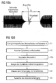
- steps of a preferred embodiment of a method for testing a contactless data communication circuit 20 are provided.
- step A1 the circuit 20 is excited by means of an energy pulse. This can be done by means of the exciter coil 130 FIG. 1 take place by cooperation with the pulse generator 110.
- the excitation is preferably carried out inductively by means of a pulsed magnetic field, wherein the magnetic field is preferably generated by a single current pulse in the form of a Dirac impact.
- step A2 a vibration of the switching circuit 20 is detected in response to the energization of the switching circuit 20.
- the measuring antenna 140 serves for this purpose FIG. 1 respectively.
- Fig. 2A The detected vibration corresponds to a free, damped oscillation of the circuit 20.
- step A3 the detected oscillation is output by an evaluation device, for example the evaluation device 160 Fig.1 , evaluated.
- an evaluation device for example the evaluation device 160 Fig.1 .
- the functionality of the circuit can be tested in this way, and in particular a self-resonant frequency and / or a quality of the circuit 20 can be determined.
- FIG. 5 A first variant of a preferred embodiment of the above with reference to Fig. 4 described method explained.
- the steps S3 to S5 correspond to the steps A1 to A3 Fig. 4
- the preferred embodiment comprises steps S1 and S2 upstream of step S3.
- step S1 an alternating magnetic field with a predetermined, defined field strength H is generated. This can be done by referring to FIG. 3 explained transmitting device 200 take place.
- step S2 the circuit 20 is arranged in the generated alternating magnetic field.
- the arrangement is such that the field strength H in the region of the antenna 22 of the circuit under test 20 is precisely adjustable, as also with reference to FIG. 3 has been described.
- Arranging the circuit 20 in the alternating field according to step S2 causes the circuit 20 due to the transmission frequency of the transmitting antenna 210 in a constant amplitude and frequency sinusoidal oscillation.
- step S3 The energization of the circuit 20 by means of the energy pulse according to step S3 results in a free, damped oscillation of the circuit 20, as exemplified in FIG. 6 is shown.
- excitation of the circuit is to be used exclusively in connection with the excitation of the circuit by means of the energy pulse (steps A1, S3).
- the influence of the alternating magnetic field which also has an effect on the vibration behavior of the circuit 20, is not understood herein to mean “excitation” of the circuit in the sense of the invention.
- FIG. 6 shows the theoretical course of a free, damped oscillation A (t) over time t.
- the function A (t) can correspond to the current I or the voltage U.
- the angular frequency ⁇ corresponds to the natural resonance frequency of the corresponding circuit 20 multiplied by 2 n. From the decay coefficient ⁇ , the quality of the circuit 20 can be determined.
- FIG. 7 shows a superposition of the mentioned, constant sinusoidal oscillation with a free, damped oscillation of the circuit 20.
- a signal can be detected by the measuring antenna 140 in step S4.
- To get out of a vibration as in FIG. 7 is shown to detect a resonant frequency of the circuit 20 to be tested, that portion of the oscillation corresponding to the constant sinusoidal oscillation generated by the alternating magnetic field must be subtracted from the detected oscillation.
- FIG. 8 One possible procedure for carrying out such an evaluation is in FIG. 8 illustrated.
- the course of the free, damped oscillation can be detected, for example, by means of the calibration antenna 310 and analyzed and stored by the evaluation device 160.
- the calibration device 300 is connected to the evaluation device 160.
- the step of analyzing may be done prior to energizing the circuit 20 by means of the energy pulse, or, as in FIG FIG. 8 illustrated, in sufficient time interval after energizing the circuit 20 by the energy pulse, namely, when the free, damped oscillation has already subsided.
- a corresponding period of time is in FIG. 8 designated T1.
- T1 A corresponding period of time is in FIG. 8 designated T1.
- FIG. 9A An example of a measurement of an operating resonance frequency of a circuit under test by means of the method according to FIG Fig. 5 is in Figure 9A shown.
- the detected total signal ie the sinusoidal vibration superimposed with the free, damped vibration, dash-dotted lines.
- the sinusoidal component corresponding to the constant alternating field was subtracted.
- the resulting signal is shown with a solid line and clearly shows the decay of the free, damped oscillation after a Dirac shock.
- Figure 9A nor the result after applying a fit algorithm, with a dashed line, where used data points are made visible.
- FIG. 9B A second measurement of the resonant frequency of the same circuit 20, but at different second constant field strength H ', is in FIG. 9B shown. It can be seen that the resonant frequency of the circuit 20 differs from the first measurement, with the first field strength H, by about 200 kHz. This is due to the field strength dependence of the resonant frequency of the circuit 20.
- FIG. 10A 2 shows the signal profile of a signal detected by the measuring antenna 140 according to an alternative test method according to a second variant of the preferred embodiment described above.
- FIG. 10B illustrate, the second variant presented here and the above with reference to the Figures 5 and 7 to 9 described first variant in steps S1 to S5.
- the second variant on which this is based deviates from the first variant described above in that the alternating magnetic field is switched off at least for a short time (compare step S2a in FIG 10B ).
- the magnetic alternating field is preferably switched off only for a short time, for example, for a period of time T2, which may be, for example, about 3 microseconds.
- T2 time
- the exciting of the circuit 20 by means of the energy pulse, for example, a direct pulse. Due to the fact that the pulse takes place very shortly after the switching off of the alternating magnetic field, the circuit 20 continues to be sufficiently supplied with energy so that switching and operating states of various elements of the circuit 20 have substantially the same state as in the case of a constant alternating field.
- the measurement result, ie the determined resonant frequency of the circuit 20 will therefore differ practically or not at all negligibly in comparison to a measurement with permanently switched alternating field.
- This second variant of the test method has the advantage that the evaluation of the detected oscillation in response to the excitation of the circuit 20 is simplified by the energy pulse.
- Figure 10A is shown, which corresponds to in step S4 FIG. 10B detected vibration according to the present second variant already only the free, damped oscillation of the circuit 20. Accordingly, can be dispensed with a subtraction of further, detected vibration components.
Abstract
Description
Die vorliegende Erfindung betrifft ein Verfahren und eine Messvorrichtung zum Prüfen eines zur kontaktlosen Datenkommunikation eingerichteten Schaltkreises eines Endgeräts, wobei der Schaltkreis eine Antenne, insbesondere eine induktiv koppelnde Antenne eines RFID- oder NFC-Moduls des Endgeräts, und ein mit der Antenne gekoppeltes elektronisches Bauteil, also insbesondere der RFID- oder NFC-Chip, umfasst. Die Erfindung umfasst weiterhin eine Breitband-Messantenne, welche eingerichtet sein kann, als Messantenne der Messvorrichtung zu dienen.The present invention relates to a method and a measuring device for testing a contactless data communication circuit of a terminal, the circuit comprising an antenna, in particular an inductively coupling antenna of an RFID or NFC module of the terminal, and an electronic component coupled to the antenna, So in particular the RFID or NFC chip includes. The invention further comprises a broadband measuring antenna, which can be set up to serve as a measuring antenna of the measuring device.
Das Prüfen des Schaltkreises kann dabei sowohl elektronische Eigenschaften des Schaltkreises als auch die Funktionsfähigkeit des Schaltkreises oder einzelner Komponenten des Schaltkreises betreffen.The testing of the circuit can affect both electronic properties of the circuit and the functionality of the circuit or individual components of the circuit.
Der Schaltkreis ist eingerichtet, in ein Endgerät integriert zu werden, wie beispielsweise ein Mobilfunkendgerät, ein Smartphone oder ein entsprechendes Lesegerät zur kontaktlosen Kommunikation mit einem kontaktlos kommunizierenden Gerät oder Datenträger. Der Schaltkreis kann insbesondere als RFID- oder NFC-Modul ausgebildet sein, welches vorgesehen ist, fest in ein Endgerät der genannten Art integriert zu werden.The circuit is adapted to be integrated in a terminal, such as a mobile station, a smartphone or a corresponding reader for contactless communication with a contactlessly communicating device or disk. The circuit may in particular be designed as an RFID or NFC module, which is intended to be integrated firmly into a terminal of the type mentioned.
Um die Funktionsfähigkeit einer Antennenspule während oder nach der Herstellung des Schaltkreises zu prüfen, sind verschiedene Verfahren bekannt. Bei einer solchen Prüfung wird im Wesentlichen geprüft, ob die Antennenspule einen Bruch aufweist und/ oder ob zwei oder mehr Spulenwindungen der Antenne versehentlich kurzgeschlossen sind. Mängel dieser Art beeinträchtigen die Funktionsfähigkeit der Antennenspule erheblich bzw. zerstören diese vollständig. Eine Prüfung des Schaltkreises, bestehend aus der Antenne und dem mit der Antenne verbundenen elektronischen Bauteil, kann, wie bereits erwähnt, auch die Funktionsfähigkeit des Bauteils oder einzelner Komponenten des Bauteils betreffen.To test the operability of an antenna coil during or after the manufacture of the circuit, various methods are known. In such a test, it is essentially checked whether the antenna coil has a break and / or whether two or more coil turns of the antenna are accidentally short-circuited. Deficiencies of this kind affect the functionality of the antenna coil significantly or destroy them completely. An examination of the circuit consisting of the antenna and the electronic component connected to the antenna can, as already mentioned, also relate to the functionality of the component or of individual components of the component.
Produktionsbegleitend erfolgt bisher zumeist eine Prüfung der Antennenspule in Form einer Gleichstrom-Widerstandsmessung. Ein solches Prüfverfahren ist aufwendig, da eine Kontaktierung der Antennenspule erforderlich ist. Weiterhin können nur bestimmte Fehler des geprüften Schaltkreises erkannt werden. Eine Fehlfunktion eines oder mehrerer Komponenten des elektronischen Bauteils oder ein Leiterbahnbruch in bestimmten Bereichen der Antenne sind auf diese Weise nicht oder kaum erkennbar.To date, production testing has mostly been carried out by testing the antenna coil in the form of a DC resistance measurement. Such a test method is expensive, since a contacting of the antenna coil is required. Furthermore, only certain errors of the tested circuit can be detected. A malfunction of one or more components of the electronic component or a conductor break in certain areas of the antenna are not or hardly recognizable in this way.
Alternativ können die Resonanzfrequenz der Antennenspule und deren Güte kontaktlos bestimmt werden. Dazu wird in der Regel ein Phasen- und Impedanz-Analysator verwendet. Ein solches, sehr aufwendiges Verfahren ist detailliert beispielsweise im "
Weiterhin können Eigenschaften des Analysators, beispielsweise die Impedanz einer Messantenne, das Ergebnis der Messung beeinflussen. Verschiedene Analysatoren und Messaufbauten führen daher in der Regel zu abweichenden Messergebnissen.Furthermore, characteristics of the analyzer, such as the impedance of a measuring antenna, can affect the result of the measurement. Various Analyzers and measurement setups therefore usually lead to deviating measurement results.
Aufgabe der vorliegenden Erfindung ist es demnach, ein Verfahren und eine Messvorrichtung zur schnellen, einfach durchzuführenden und kostengünstigen Prüfung eines Schaltkreises mit induktiv koppelnder Antenne in einem Endgerät, insbesondere hinsichtlich dessen Eigenresonanzfrequenz, vorzuschlagen. Bevorzugt soll das Verfahren eine präzise und reproduzierbare Messung insbesondere der Eigenresonanzfrequenz des Schaltkreises erlauben.The object of the present invention is therefore to propose a method and a measuring device for a quick, easy and cost-effective testing of a circuit with inductively coupling antenna in a terminal, in particular with regard to its natural resonance frequency. Preferably, the method should allow a precise and reproducible measurement, in particular the natural resonant frequency of the circuit.
Diese Aufgabe wird durch ein Verfahren und eine Messvorrichtung mit den Merkmalen der unabhängigen Ansprüche gelöst. Vorteilhafte Ausgestaltungen und Weiterbildungen der Erfindung sind in den abhängigen Ansprüchen angegeben.This object is achieved by a method and a measuring device having the features of the independent claims. Advantageous embodiments and further developments of the invention are specified in the dependent claims.
Ein Grundgedanke der vorliegenden Erfindung besteht darin, den zu prüfenden Schaltkreis mittels eines Energiepulses zur Schwingung anzuregen und die durch die Anregung erzeugte Schwingung des Schaltkreises, welche einer freien, gedämpften Schwingung entspricht, zu erfassen und auszuwerten. Aus der erfassten Schwingung können dann, wie nachfolgend im Detail beschrieben, Eigenschaften des Schaltkreises abgelesenen werden, wie beispielsweise die Eigenresonanzfrequenz oder die Güte des Schaltkreises.A basic idea of the present invention is to excite the circuit to be tested by means of an energy pulse and to detect and evaluate the oscillation of the circuit generated by the excitation, which corresponds to a free, damped oscillation. From the detected oscillation properties of the circuit can then be read, as described in detail below, such as the natural resonant frequency or the quality of the circuit.
Ein erfindungsgemäßes Verfahren zum Prüfen eines zur kontaktlosen Datenkommunikation eingerichteten Schaltkreises eines Endgeräts, wobei der Schaltkreis eine induktiv koppelnde Antenne, insbesondere eine RFID- oder NFC-Antennenspule eines RFID- oder NFC-Moduls des Endgeräts, und ein mit der Antenne gekoppeltes elektronisches Bauteil umfasst. Die Antenne ist vorzugsweise eine Antennenspule mit mindestens einer Leiterschleife. Das Verfahren umfasst die folgenden Schritte:
- Der elektronische Schaltkreis wird in einem ersten Schritt mittels eines Energiepulses zur Schwingung angeregt. In der Regel erfolgt das Anregen des Schaltkreises als induktives Anregen mittels eines gepulsten Magnetfeldes. Das Magnetfeld wird dabei vorzugsweise durch einen einzelnen Strompuls erzeugt. Der Strompuls kann dabei vorzugsweise als Gleichstrompuls in Form eines Dirac-Stoßes erzeugt werden. Alternativ kann auch ein Strompuls erzeugt werden, der lediglich eine steile Flanke aufweist. Vorzugsweise erfolgt das Anregen des Schaltkreises kontaktlos mittels einer externen Erregerspule.
- The electronic circuit is excited to vibrate in a first step by means of an energy pulse. In general, the exciting of the circuit takes place as inductive excitation by means of a pulsed magnetic field. The magnetic field is preferably generated by a single current pulse. The current pulse can be generated preferably as a DC pulse in the form of a Dirac impact. Alternatively, it is also possible to generate a current pulse which has only one steep edge. Preferably, the exciting of the circuit is made contactless by means of an external excitation coil.
In einem weiteren Schritt wird die Schwingung des Schaltkreises in Antwort auf die Anregung des Schaltkreises durch den Energiepuls erfasst. Das Erfassen der Schwingung des Schaltkreises erfolgt ebenfalls vorzugsweise kontaktlos mittels einer externen Messantenne. Erregerspule und Messantenne werden dabei vorzugsweise in unmittelbarer Nähe des zu prüfenden Schaltkreises angeordnet.In a further step, the oscillation of the circuit is detected in response to the excitation of the circuit by the energy pulse. The detection of the oscillation of the circuit is also preferably carried out without contact by means of an external measuring antenna. Exciting coil and measuring antenna are preferably arranged in the immediate vicinity of the circuit under test.
Die erfasste Schwingung des Schaltkreises wird schließlich ausgewertet, insbesondere hinsichtlich einer Eigenresonanzfrequenz und / oder Güte des Schaltkreises. Dies kann mittels einer Auswertungseinrichtung erfolgen, die mit der Messantenne verbunden ist.The detected oscillation of the circuit is finally evaluated, in particular with regard to a natural resonance frequency and / or quality of the circuit. This can be done by means of an evaluation device which is connected to the measuring antenna.
Eine erfindungsgemäße Messvorrichtung zum Prüfen eines zur kontaktlosen Datenkommunikation eingerichteten Schaltkreises umfasst dabei folgende Komponenten:
- Ein Impulsgeber ist eingerichtet, einen in der Messvorrichtung anordenbaren, zu prüfenden Schaltkreis über eine an den Impulsgeber angeschlossene Erregerspule kontaktlos anzuregen.
- A pulse generator is set up to contactlessly excite a circuit to be tested, which can be arranged in the measuring device, by means of an excitation coil connected to the pulse generator.
Eine Messantenne ist eingerichtet, eine Schwingung eines angeordneten, zu prüfenden Schaltkreises zu erfassen.A measuring antenna is arranged to detect a vibration of an arranged circuit to be tested.
Eine Auswertungseinrichtung schließlich, welche mit der Messantenne verbunden ist, ist eingerichtet, die von der Messantenne erfasste Schwingung des zu prüfenden Schaltkreises auszuwerten, insbesondere hinsichtlich einer Eigenresonanzfrequenz des Schaltkreises.Finally, an evaluation device, which is connected to the measuring antenna, is set up to evaluate the oscillation of the circuit to be tested detected by the measuring antenna, in particular with regard to a self-resonant frequency of the circuit.
Die Auswertungseinrichtung kann dabei insbesondere einen Vergleich mit Referenzwerten einer intakten Antennenspule heranziehen. Zur Analyse der von der Messantenne beim Erfassen der Schwingung, d.h. der freien, gedämpften Schwingung, erfassten Signale kann in bekannter Weise beispielsweise ein digitaler Signalprozessor (DSP) oder ein Oszilloskop dienen.The evaluation device can in particular use a comparison with reference values of an intact antenna coil. For analysis of the from the measuring antenna when detecting the vibration, i. The free, damped vibration, detected signals can serve in a known manner, for example, a digital signal processor (DSP) or an oscilloscope.
Ein durch einen Energiepuls angeregter Schaltkreis schwingt nach der Anregung grundsätzlich unmittelbar mit einer freien, gedämpften Schwingung A(t) aus, welche mit der folgenden Formel beschrieben werden kann: ![]()
![]()
A(t) kann dabei dem Strom I oder der Spannung U eines durch den Schaltkreis gebildeten elektrischen Schwingkreises entsprechen. Demnach kann der Spannungsverlauf des Schaltkreises unmittelbar nach der Anregung mit der folgenden Formel beschrieben werden: 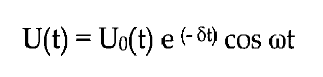
Die Kreisfrequenz ω entspricht dabei der Eigenresonanzfrequenz des Schaltkreises fres multipliziert mit 2 n (ω =2 n fres). Aus dem Abklingkoeffizienten δ und der Eigenresonanzfrequenz fres kann die Güte Q des Schaltkreises ermittelt werden. Alternativ kann die Güte Q auch aus zwei aufeinander folgenden Maxima An und An+1 der Schwingungsamplitude des Schaltkreises ermittelt werden. 
Je länger der Abklingvorgang dauert, desto höher ist die Güte des entsprechenden Schwingkreises. D.h. eine Auswertung der freien, gedämpften Schwingung des Schaltkreises, d. h. deren Ausschwingen unmittelbar nach der Anregung, erlaubt es, sowohl die Eigenresonanzfrequenz als auch die Güte des Schaltkreises zu bestimmen.The longer the decay process lasts, the higher the quality of the corresponding resonant circuit. That an evaluation of the free, damped oscillation of the circuit, d. H. their decay immediately after the excitation, allows to determine both the natural frequency and the quality of the circuit.
Ein Aspekt der Erfindung beruht nun auf dem Umstand, dass ein Defekt der Antenne des zu prüfenden Schaltkreises, wie beispielsweise eine Unterbrechung einer Leiterbahn oder ein Kurzschluss zwischen einzelnen Spulenwindungen einer als Antennenspule ausgebildeten Antenne, dazu führt, dass sich ein bei einer beschriebenen Prüfung erkennbarer Signalverlauf des Ausschwingens signifikant von einem entsprechenden Signalverlauf des Ausschwingens einer intakten Antennenspule unterscheidet. Anhand der ausgewerteten freien, gedämpften Schwingung festgestellte Parameter einer fehlerhaften Antenne, insbesondere deren Eigenresonanzfrequenz und deren Güte, unterscheiden sich deutlich von den entsprechenden Parametern einer intakten Antenne.One aspect of the invention is based on the circumstance that a defect in the antenna of the circuit under test, such as an interruption of a conductor track or a short circuit between individual coil windings of an antenna designed as an antenna coil, leads to a recognizable signal curve in a test described of the swing-out significantly different from a corresponding waveform of the swinging out of an intact antenna coil. On the basis of the evaluated free, damped vibration detected parameters of a faulty antenna, in particular their natural frequency and their quality, differ significantly from the corresponding parameters of an intact antenna.
Ein Leiterbahnbruch beispielsweise zeigt sich in einem deutlich erkennbar veränderten Ausschwingverhalten, insbesondere einer veränderten, in der Regel erhöhten Eigenresonanzfrequenz. Im Falle eines Kurzschlusses von zwei oder mehr Spulenwindungen ist kaum mehr ein Ausschwingen zu beobachten.A conductor break, for example, is reflected in a clearly recognizable changed decay behavior, in particular an altered, usually increased natural resonant frequency. In the case of a short circuit of two or more coil turns barring is no longer observed.
Auf diese Weise kann beim Auswerten der freien, gedämpften Schwingung durch die Prüfvorrichtung nicht nur erkannt werden, ob die Antennenspule fehlerhaft ist oder nicht, sondern es kann im Falle eines Fehlers oder Mangels auch der Typ des Fehlers bzw. die Art des Mangels festgestellt werden.In this way, when evaluating the free, damped vibration by the test apparatus, not only can it be known whether the antenna coil is faulty or not, but also the type of the fault or the type of defect can be determined in case of a fault or defect.
Die Vorteile des erfindungsgemäßen Verfahrens sind offensichtlich und zahlreich. Die Prüfung des Schaltkreises, insbesondere der Antenne des Schaltkreises, kann kontaktlos und mit sehr geringem Zeitaufwand erfolgen. Dies erlaubt für geeignete Ausführungsformen von Schaltkreisen eine Prüfung während eines laufenden Produktionsprozesses. Insbesondere kann auch bereits eine gedruckte Antennenspule, welche noch nicht vollständig ausgehärtet ist, mit dem erfindungsgemäßen Verfahren geprüft werden. Die benötigte Messvorrichtung ist vergleichsweise einfach und kostengünstig bereitzustellen. Zudem erlaubt das Verfahren nicht nur, Fehler oder Mängel einer defekten Antenne des Schaltkreises zu erkennen, sondern auch verschiedene Fehlertypen eines zu prüfenden Schaltkreises zu unterscheiden.The advantages of the method according to the invention are obvious and numerous. The test of the circuit, in particular the antenna of the circuit, can be done contactless and with very little time. This allows for suitable embodiments of circuits a test during an ongoing production process. In particular, even a printed antenna coil, which has not yet completely cured, can be tested with the method according to the invention. The required measuring device is comparatively easy and inexpensive to provide. In addition, the method not only allows to detect faults or defects of a defective antenna of the circuit, but also to distinguish different types of faults of a circuit under test.
Ein weiterer Aspekt der Erfindung betrifft eine Breitband-Messantenne. Diese kann eingerichtet sein, als Messantenne der vorstehend beschriebenen, erfindungsgemäßen Messvorrichtung zu dienen.Another aspect of the invention relates to a broadband antenna. This can be set up to serve as a measuring antenna of the measuring device according to the invention described above.
Grundsätzlich sollte eine Messantenne der betreffenden Art, d.h. eine Messantenne, die eingerichtet ist, eine Schwingung, beispielsweise eines gemäß dem erfindungsgemäßen Verfahren angeregten Schaltkreises, zu erfassen, bestimmte technischen Eigenschaften zeigen. Eine solche Messantenne sollte derart ausgebildet sein, dass sie selbst durch ihre physikalischen Eigenschaften eine Messung, beispielsweise einer Schwingung eines Schaltkreises, nicht oder nur unwesentlich beeinflusst. Dazu sollte die Messantenne möglichst breitbandig ausgelegt sein und lediglich eine sehr gering ausgeprägte Spannungsüberhöhung im Bereich ihrer Resonanzfrequenz aufweisen. Insbesondere sollte ein Ausschwingen der Messantenne, beispielsweise in Reaktion auf eine Anregung, im Wesentlichen unterdrückt werden.Basically, a measuring antenna of the type in question, i. a measuring antenna which is set up to detect a vibration, for example of a circuit excited according to the method according to the invention, has certain technical properties. Such a measuring antenna should be designed in such a way that it does not or only insignificantly influences a measurement, for example a vibration of a circuit, by its physical properties. For this purpose, the measuring antenna should be designed as broadband as possible and only have a very slight increase in voltage in the range of their resonance frequency. In particular, a decay of the measuring antenna, for example in response to an excitation, should be substantially suppressed.
Um dies zu erreichen, umfasst eine erfindungsgemäße Breitband-Messantenne eine Leiterschleife und eine Mehrzahl ohmscher Widerstände. Die Widerstände sind in vorgegebenen Abständen entlang der Leiterschleife in die Leiterschleife eingefügt. Mit anderen Worten, durch das Einfügen der Widerstände in die Leiterschleife entsteht eine Mehrzahl von Leitungssegmenten der Leiterschleife. Entlang der Leiterschleife benachbarte Leitungssegmente sind dabei durch je einen der ohmschen Widerstände verbunden. Dadurch sind Leitungssegmente und Widerstände jeweils abwechselnd und in Reihe geschaltet.In order to achieve this, a broadband measuring antenna according to the invention comprises a conductor loop and a plurality of ohmic resistors. The resistors are inserted at predetermined intervals along the conductor loop in the conductor loop. In other words, by inserting the resistors into the conductor loop, a plurality of line segments of the conductor loop are formed. Along the conductor loop adjacent line segments are connected by one of the ohmic resistors. As a result, line segments and resistors are alternately and connected in series.
Auf diese Weise entsteht eine Leiterschleife mit dazu in Reihe geschaltetem hochohmigem Widerstand. Dies könnte zwar grundsätzlich auch dadurch erreicht werden, dass ein einzelner hochohmiger Widerstand in Reihe mit der Leiterschleife geschaltet wird. Da in der Praxis aber auch parasitäre Kapazitäten in Betracht gezogen werden müssen, die sich entlang der Leiterschleifen bilden, hat der beschriebene Aufbau der erfindungsgemäßen Breitband-Messantenne verschiedene Vorteile.In this way, a conductor loop with a high-resistance resistor connected in series is created. In principle, this could also be achieved by connecting a single high-resistance resistor in series with the conductor loop. However, since parasitic capacitances that form along the conductor loops must also be taken into consideration in practice, the described structure of the broadband measurement antenna according to the invention has various advantages.
Dadurch, dass der Widerstand nicht als einzelner Widerstand vorliegt, sondern als Mehrzahl entlang der Leiterschleife geschalteter "Teilwiderstände", werden die auftretenden parasitären Kapazitäten nicht mehr als Gesamtkapazität wirksam. Mit anderen Worten, während ein einzelner Widerstand, der in Reihe zu der Leiterschleife geschaltet werden würde, aufgrund einer entlang der Leiterschleife auftretenden parasitären Kapazität, welche dann als Gesamtkapazität in Erscheinung treten würde, zusammen mit der Induktivität der Leiterschleife einen Schwingkreis mit ungünstigerweise hoher Güte - wegen des hochohmigen Scheinwiderstandes - bilden würde, erlaubt der erfindungsgemäße Aufbau eine wirksame Dämpfung der Breitband-Messantenne.Because the resistor is not present as a single resistor but as a plurality of "partial resistors" connected along the conductor loop, the parasitic capacitances that occur are no longer effective as a total capacitance. In other words, while a single resistor that would be connected in series with the conductor loop, due to a parasitic capacitance occurring along the conductor loop, which would then appear as a total capacitance, together with the inductance of the conductor loop, a resonant circuit with unfavorably high quality, because of the high impedance impedance - would form the structure of the invention allows effective attenuation of the broadband antenna.
Gegenüber einer Ausführungsform, bei der der Widerstand dadurch entlang der Leiterschleife "gleichmäßig" verteilt wird, dass die Leiterschleife einer Messantenne aus einem hochohmigen Material, wie beispielsweise Graphit, hergestellt wird, hat der beschriebene, erfindungsgemäße Aufbau den Vorteil einer einfachen und insbesondere kostengünstigeren Herstellung.Compared to an embodiment in which the resistance is distributed "evenly" along the conductor loop, that the conductor loop of a measuring antenna made of a high-resistance material, such as graphite, is produced, the described structure according to the invention has the advantage of a simple and more cost-effective production.
Ein weiterer Vorteil der erfindungsgemäßen Breitband-Messantenne besteht darin, dass, bedingt durch den hohen Widerstand der Leiterschleife, ein während einer Messung, beispielsweise im Rahmen des erfindungsgemäßen Verfahrens, in der Antenne fließender Strom gegen Null geht. Mit anderen Worten, an den Anschlüssen der Breitband-Messantenne wird praktisch nur Spannung gemessen. Wird aber der Strom in der Breitband-Messantenne sehr klein, so wird dadurch auch eine Rückwirkung auf einen Messgegenstand, beispielsweise eine Antenne eines zu prüfenden Schaltkreises, minimiert. Dadurch wird das Messergebnis durch die Breitband-Messantenne praktisch nicht beeinflusst.A further advantage of the broadband measuring antenna according to the invention is that, due to the high resistance of the conductor loop, a current flowing in the antenna during a measurement, for example in the context of the method according to the invention, approaches zero. In other words, at the terminals of the broadband measuring antenna, practically only voltage is measured. However, if the current in the broadband measuring antenna becomes very small, a reaction to a measuring object, for example an antenna of a circuit to be tested, is thereby minimized. As a result, the measurement result is virtually unaffected by the broadband antenna.
Die Abstände zwischen je zwei entlang der Leiterschleife benachbart eingefügten Widerständen sind dabei vorzugsweise regelmäßig. Die Anzahl, der Abstand und die Dimension der Widerstände sind grundsätzlich variabel. Vorzugsweise werden zumindest fünf Widerstände entlang der Leiterschleife angeordnet, vorzugsweise 8 bis 10 Widerstände, die Anzahl kann aber auch größer sein. In der Regel sind die Widerstände gleich dimensioniert, Abweichungen zwischen einzelnen Widerstandswerten sind möglich.The distances between each two adjacent along the conductor loop inserted resistors are preferably regular. The number, the distance and the dimension of the resistors are basically variable. Preferably, at least five resistors are arranged along the conductor loop, preferably 8 to 10 resistors, but the number can also be greater. In general, the resistors are dimensioned the same, deviations between individual resistance values are possible.
Im Rahmen des erfindungsgemäßen Prüfverfahrens und mit Bezug auf eine erfindungsgemäße Messvorrichtung werden die Erregerspule und die Messantenne der Messvorrichtung, beispielsweise die erfindungsgemäße Breitbandantenne, vorzugsweise orthogonal zueinander angeordnet. In dem Fall, dass die Erregerspule und die Messantenne nicht orthogonal zueinander, sondern beispielsweise nebeneinander angeordnet sind, wird der Erregungspuls der Erregerspule auch von der Messantenne erfasst. Zudem überlagert dann das Abschwingverhalten der Erregerspule das zu messende Abschwingverhalten der Antennenspule.Within the scope of the test method according to the invention and with reference to a measuring device according to the invention, the exciter coil and the measuring antenna of the measuring device, for example the broadband antenna according to the invention, are preferably arranged orthogonal to one another. In the case that the exciter coil and the measuring antenna are arranged not orthogonal to each other, but for example next to each other, the excitation pulse of the exciter coil is also detected by the measuring antenna. In addition, the Abschwingverhalten the exciter coil then superimposed on the Abschwingverhalten the antenna coil to be measured.
Bei einer "orthogonalen" Anordnung der Erregerspule zu der Messantenne liegen diese derart zueinander, dass das Signal der Erregerspule von der Messantenne nicht wahrgenommen wird. Die Erregerspule ist dabei gegenüber der Messantenne räumlich so angeordnet, dass in der Messantenne im Wesentlichen kein Signal eingekoppelt wird. Ein Signal wird in eine Spule immer dann eingekoppelt, wenn das Ringintegral über den magnetischen Fluss Φ durch diese Spule größer als Null ist (vgl. oben zitiertes RFID-Handbuch, Kapitel 4.1.6 und 4.1.9.2). Das Integral über den magnetischen Fluss Φ ist genau dann Null, wenn sich magnetische Feldlinien unterschiedlicher Richtung und Feldstärke in der Messantenne über die Gesamtfläche gegenseitig aufheben, oder wenn der Winkel der Feldlinien zur Spulenachse genau 90° beträgt - daher der Begriff "orthogonale" Anordnung. Eine geeignete, so genannte koplanare orthogonale Anordnung der Erregerspule zur Messantenne kann beispielsweise derart erfolgen, dass die beiden Antennen in einer Ebene geeignet teilweise übereinander liegen.In an "orthogonal" arrangement of the excitation coil to the measuring antenna, these are such to each other that the signal of the excitation coil is not perceived by the measuring antenna. The excitation coil is arranged spatially relative to the measuring antenna in such a way that substantially no signal is coupled into the measuring antenna. A signal is coupled into a coil whenever the ring integral across the magnetic flux Φ through this coil is greater than zero (see RFID Handbook, chapters 4.1.6 and 4.1.9.2 cited above). The integral over the magnetic flux Φ is zero if and only if magnetic field lines of different direction and field strength in the measuring antenna over the total area cancel each other, or if the angle of the field lines to the coil axis is exactly 90 ° - hence the term "orthogonal" arrangement. A suitable, so-called coplanar orthogonal arrangement of the exciting coil to the measuring antenna, for example, take place such that the two antennas in a plane suitably lie partially above each other.
Vorzugsweise ist an die Messantenne der Messvorrichtung unmittelbar ein Verstärker angeordnet. Dadurch kann eine lange, kapazitätsbelegte Zuleitung vermieden werden. Der Verstärker umfasst bevorzugt einen hochohmigen Eingang. Als Verstärker kann beispielsweise ein Impedanzwandler verwendet werden. Dessen Ausgangsimpedanz ist dann vorzugsweise an ein Übertragungsmittel angepasst, welches den Impedanzwandler mit der Auswertungseinrichtung verbindet. Als Verbindungsmittel wird vorzugsweise ein Koaxialkabel verwendet. In diesem Fall beträgt die Ausgangsimpedanz des Impedanzwandlers 50 Ω.Preferably, an amplifier is arranged directly on the measuring antenna of the measuring device. As a result, a long, capacitive supply line can be avoided. The amplifier preferably comprises a high-impedance input. As an amplifier, for example, an impedance converter can be used. Its output impedance is then preferably adapted to a transmission means which connects the impedance converter with the evaluation device. As a connecting means, a coaxial cable is preferably used. In this case, the output impedance of the impedance converter is 50 Ω.
Die Auswertungseinrichtung, welche beispielsweise ein Oszilloskop sein kann, weist bevorzugt eine Eingangsimpedanz auf, welche in gleicher Weise an ein Übertragungsmittel angepasst ist, welches die Auswertungseinrichtung mit der Messantenne verbindet, beispielsweise das genannte Koaxialkabel.The evaluation device, which may be, for example, an oscilloscope, preferably has an input impedance which is adapted in the same way to a transmission means which connects the evaluation device to the measuring antenna, for example the said coaxial cable.
Ein Aspekt einer bevorzugten Ausführungsform der vorliegenden Erfindung basiert weiterhin auf der Erkenntnis, dass elektrische Eigenschaften eines zu prüfenden Schaltkreises, insbesondere die Eigenresonanzfrequenz und die Güte des Schaltkreises, abhängig sind von der Feldstärke eines magnetischen Wechselfeldes, in dem sich der Schaltkreis während oder kurz vor der Messung, d.h. der Anregung durch den Energiepuls, befindet. Da bekannte Verfahren diese Einflussgröße bisher unbeachtet gelassen haben, waren genaue und reproduzierbare Messungen entsprechender Eigenschaften nicht möglich.An aspect of a preferred embodiment of the present invention is further based on the recognition that electrical properties of a circuit to be tested, in particular the natural frequency and the quality of the circuit, are dependent on the field strength of an alternating magnetic field in which the circuit during or shortly before the Measurement, ie the excitation by the energy pulse, is located. Since known methods have so far ignored this factor, they were accurate and reproducible measurements of corresponding properties are not possible.
Ein Grund für die Feldstärkeabhängigkeit der Resonanzfrequenz und der Güte eines entsprechenden Schaltkreises liegt in den physikalischen Eigenschaften elektronischer Komponenten des Schaltkreises. Zur Gewinnung einer Versorgungsspannung eines Chips des Schaltkreises kann die Antenne des Schaltkreises mit einem Gleichrichterbauteil verbunden sein. Die von der Antenne gesehene Impedanz des Gleichrichters hängt dabei von dem Strom ab, welcher in den Gleichrichter fließt. Weitere Einflussgrößen sind spannungsabhängige Sperrschichtkapazitäten des Gleichrichterbauteils sowie gegebenenfalls Transistorbauteile auf dem Chip, der dynamische Gleich- und Wechselstromwiderstand des Gleichrichterbauteils sowie eine daraus resultierende Eingangskapazität des Chips. Mit anderen Worten, die Resonanzfrequenz des Schaltkreises hängt indirekt aus den genannten Gründen von einem magnetischen Wechselfeld ab, in dem sich der Schaltkreis während der Messung befindet.One reason for the field strength dependence of the resonant frequency and the quality of a corresponding circuit resides in the physical properties of electronic components of the circuit. To obtain a supply voltage of a chip of the circuit, the antenna of the circuit may be connected to a rectifier component. The impedance of the rectifier seen by the antenna depends on the current flowing into the rectifier. Further influencing factors are voltage-dependent junction capacitances of the rectifier component and optionally transistor components on the chip, the dynamic DC and AC resistance of the rectifier component and a resulting input capacitance of the chip. In other words, the resonant frequency of the circuit depends indirectly on the above reasons of an alternating magnetic field in which the circuit is located during the measurement.
Um diesem Umstand Rechnung zu tragen, zeichnet sich eine bevorzugte Ausführungsform des erfindungsgemäßen Verfahrens dadurch aus, dass das Auswerten der erfassten Schwingung in Abhängigkeit von der Feldstärke eines magnetischen Wechselfeldes erfolgt, in welchem der Schaltkreis angeordnet ist.In order to take this circumstance into account, a preferred embodiment of the method according to the invention is characterized in that the evaluation of the detected oscillation takes place as a function of the field strength of an alternating magnetic field in which the circuit is arranged.
Das Auswerten der erfassten Schwingung kann insbesondere in Abhängigkeit eines durch das Vorliegen des magnetischen Wechselfeldes bedingten Betriebs- oder Schaltungszustandes einer oder mehrerer Komponenten des elektronischen Bauteils des Schaltkreises erfolgen. Die angesprochenen Betriebs- oder Schaltungszustände können beispielsweise die Ladung eines Kondensators betreffen oder den Stromfluss durch ein Gleichrichter-Bauteil.The evaluation of the detected oscillation can be effected in particular as a function of a condition of operation or switching of one or more components of the electronic component of the circuit due to the presence of the alternating magnetic field. The mentioned operating or circuit states may concern, for example, the charge of a capacitor or the current flow through a rectifier device.
Eine konkrete Ausgestaltung der bevorzugten Ausführungsform des erfindungsgemäßen Verfahrens umfasst demnach die weiteren Schritte des Erzeugens eines magnetischen Wechselfeldes vorgegebener Feldstärke und des Anordnens des Schaltkreises in dem Wechselfeld. Die beiden Schritte werden dabei vor dem Schritt des Anregens des Schaltkreises mittels des Energiepulses durchgeführt.A specific embodiment of the preferred embodiment of the method according to the invention therefore comprises the further steps of generating an alternating magnetic field of predetermined field strength and arranging the circuit in the alternating field. The two steps are performed before the step of exciting the circuit by means of the energy pulse.
Das magnetische Wechselfeld kann dabei mittels einer Sendeantenne erzeugt werden. Weiterhin kann vorgesehen sein, die Feldstärke des Wechselfeldes in einem vorgegebenen Bereich mittels einer Kalibrierantenne zu messen, um ein Erzeugen des Wechselfeldes gemäß der vorgegebenen Feldstärke in präziser und nachprüfbarer Weise zu ermöglichen.The magnetic alternating field can be generated by means of a transmitting antenna. Furthermore, it can be provided to measure the field strength of the alternating field in a predetermined range by means of a calibration antenna, in order to enable the alternating field to be generated according to the predetermined field strength in a precise and verifiable manner.
Die Kalibrierantenne und die Antenne des zu prüfenden Schaltkreises werden dabei vorzugsweise derart relativ zur Sendeantenne angeordnet, dass im Bereich der Kalibrierantenne und im Bereich der Antenne des Schaltkreises jeweils ein magnetisches Wechselfeld der gleichen Feldstärke vorliegt. Auf diese Weise wird es ermöglicht, dass die Prüfung des Schaltkreises in einer genau vorgebbaren, standardisierten Umgebung, d.h. bei einem in vorgegebener Feldstärke vorliegenden magnetischen Wechselfeld, durchgeführt werden kann. Dies erlaubt erstmals eine sehr präzise und reproduzierbare Messung der entsprechenden physikalischen Eigenschaften des Schaltkreises, insbesondere der Resonanzfrequenz und der Güte des Schaltkreises.The calibration antenna and the antenna of the circuit to be tested are preferably arranged relative to the transmitting antenna in such a way that in each case an alternating magnetic field of the same field strength is present in the region of the calibration antenna and in the region of the antenna of the circuit. In this way, the testing of the circuit in a predetermined, standardized environment, i. can be performed at an existing magnetic field in a predetermined field strength. This allows for the first time a very precise and reproducible measurement of the corresponding physical properties of the circuit, in particular the resonant frequency and the quality of the circuit.
Das magnetische Wechselfeld wird dabei derart erzeugt, dass der darin angeordnete Schaltkreis in eine bezüglich Amplitude und Frequenz konstante sinusförmige Schwingung versetzt wird. Die Frequenz entspricht dabei vorzugsweise einer Betriebsfrequenz des Schaltkreises, beispielsweise eine Frequenz von 13,56 MHz.The magnetic alternating field is generated in such a way that the circuit arranged therein in a respect to amplitude and frequency constant sinusoidal oscillation is added. The frequency preferably corresponds to an operating frequency of the circuit, for example a frequency of 13.56 MHz.
Gemäß einer ersten Variante der bevorzugten Ausführungsform des erfindungsgemäßen Verfahrens wird der Schaltkreis, wie beschrieben, im Bereich des magnetischen Wechselfeldes angeordnet und das Wechselfeld liegt zum Zeitpunkt des Anregens des Schaltkreises mittels des Energiepulses in konstanter Weise vor. Mit anderen Worten, das Anregen des Schaltkreises durch den Energiepuls erfolgt bei dauerhaft angeschaltetem magnetischem Wechselfeld. Beim Auswerten der erfassten Schwingung wird dann derjenige Anteil der erfassten Schwingung berücksichtigt, welcher durch das Wechselfeld hervorgerufen wird. Dabei handelt es sich um die vorstehend erwähnte, konstante sinusförmige Schwingung.According to a first variant of the preferred embodiment of the method according to the invention, the circuit, as described, arranged in the region of the alternating magnetic field and the alternating field is at the time of excitation of the circuit by means of the energy pulse in a constant manner. In other words, the energizing of the circuit by the energy pulse takes place with permanently switched magnetic alternating field. When evaluating the detected oscillation, the portion of the detected oscillation caused by the alternating field is taken into account. This is the above-mentioned, constant sinusoidal oscillation.
Im Rahmen dieser ersten Variante umfasst das Erfassen der Schwingung des Schaltkreises ein Erfassen einer Überlagerung einer durch das Wechselfeld hervorgerufenen sinusförmigen Schwingung des Schaltkreises mit einer freien, gedämpften Schwingung des Schaltkreises, welche aus der Anregung des Schaltkreises durch den Energiepuls resultiert.In the context of this first variant, detecting the oscillation of the circuit comprises detecting a superimposition of a sinusoidal oscillation of the circuit caused by the alternating field with a free, damped oscillation of the circuit resulting from the excitation of the circuit by the energy pulse.
Das Auswerten der erfassten Schwingung des Schaltkreises kann mittels einer Subtraktion der konstanten sinusförmigen Schwingung von der erfassten Schwingung erfolgen. Auf diese Weise kann die freie, gedämpfte Schwingung des Schaltkreises ermittelt werden.The evaluation of the detected oscillation of the circuit can be carried out by means of a subtraction of the constant sinusoidal oscillation from the detected oscillation. In this way, the free, damped oscillation of the circuit can be determined.
Um eine solche Vorgehensweise zu unterstützen, kann die sinusförmige Schwingung vor dem Anregen durch den Energiepuls, oder in hinreichendem Abstand nach dem Anregen, d.h. wenn die freie, gedämpfte Schwingung bereits ausgeklungen ist, erfasst und hinsichtlich Amplitude, Phase und Frequenz ermittelt und in einer Auswertungseinrichtung gespeichert werden.To support such a procedure, the sinusoidal oscillation may be prior to being excited by the energy pulse, or at a sufficient distance after excitation, ie, when the free, damped oscillation has already decayed, detected and determined in terms of amplitude, phase and frequency and stored in an evaluation device.
Die Subtraktion der konstanten sinusförmigen Schwingung von der erfassten Schwingung des Schaltkreises kann mittels Software oder mittels Hardware erfolgen. In der Hardwarevariante kann ein Verstärker verwendet werden. Die beschriebene Subtraktion kann dann vorzugsweise durch Addition eines Signals erfolgen, welches dem von der Kalibrierantenne erfassten und dann invertierten Signal entspricht, d.h. durch Addition der invertierten Sinusschwingung.The subtraction of the constant sinusoidal oscillation from the detected oscillation of the circuit can be done by software or hardware. In the hardware variant, an amplifier can be used. The described subtraction can then preferably be done by adding a signal which corresponds to the signal detected by the calibration antenna and then inverted, i. by adding the inverted sine wave.
Ein Aspekt des Verfahrens gemäß der vorstehend beschriebenen, bevorzugten Ausführungsform betrifft eine präzise Messung der Eigenresonanzfrequenz des Schaltkreises unter vorgegebenen äußeren Bedingungen, d.h. in einem magnetischen Wechselfeld konstanter, vorgegebener Feldstärke. Dies erlaubt eine entsprechende Messung in reproduzierbarer Weise und insbesondere bei einer Betriebsfeldstärke des Schaltkreises.One aspect of the method according to the preferred embodiment described above relates to a precise measurement of the self-resonant frequency of the circuit under given external conditions, i. in an alternating magnetic field of constant, predetermined field strength. This allows a corresponding measurement in a reproducible manner and in particular at an operating field strength of the circuit.
Ein weiterer Aspekt dieser Ausführungsform betrifft schließlich die Tatsache, dass bei Vorliegen eines intakten Schaltkreises bei verschiedenen Feldstärken jeweils, wenn auch gegebenenfalls nur geringfügig, voneinander abweichende Resonanzfrequenzen ermittelt werden sollten. Mit anderen Worten, werden bei wiederholtem Durchführen des beschriebenen Verfahrens gemäß der bevorzugten Ausführungsform - bei jeweils verschiedenen Feldstärken des magnetischen Wechselfeldes - gleiche Resonanzfrequenzen ermittelt, so spricht dies für einen Defekt des elektronischen Bauteils bzw. solcher Elemente des Bauteils, welche grundsätzlich mit für eine Abhängigkeit der Resonanzfrequenz von der Feldstärke verantwortlich sind.Finally, another aspect of this embodiment relates to the fact that in the presence of an intact circuit at different field strengths each, albeit possibly only slightly different resonant frequencies should be determined. In other words, if repeated execution of the described method according to the preferred embodiment - at different field strengths of the alternating magnetic field - same resonant frequencies determined, this speaks for a defect of the electronic component or such elements of the component, which basically with a dependency the resonance frequency of the field strength are responsible.
Das Verfahren gemäß der bevorzugten Ausführungsform liefert daher folgende zusätzliche Vorteile. Erstmals kann die Resonanzfrequenz eine RFID- oder NFC-Moduls eines Endgeräts präzise und reproduzierbar, unter variabel, aber fest einstellbaren Bedingungen, ermittelt werden. Ein bisher nicht erfassbarer Einfluss eines magnetischen Wechselfeldes auf Messergebisse kann nun in präziser Weise vorgegeben und in der Messung berücksichtigt werden. Dies ermöglicht eine präzise Messung physikalischer Eigenschaften des betreffenden Schaltkreises unter eindeutig reproduzierbaren Messbedingungen.The method according to the preferred embodiment therefore provides the following additional advantages. For the first time, the resonant frequency of an RFID or NFC module of a terminal can be determined precisely and reproducibly, under variable but permanently adjustable conditions. An influence of an alternating magnetic field which can not be detected on measurement results can now be specified in a precise manner and taken into account in the measurement. This enables a precise measurement of physical properties of the relevant circuit under clearly reproducible measurement conditions.
Gemäß einer zweiten Variante der bevorzugten Ausführungsform des erfindungsgemäßen Verfahrens kann der Schaltkreis im Bereich des magnetischen Wechselfeldes angeordnet werden und das Wechselfeld zum Zeitpunkt des Anregens des Schaltkreises mittels des Energiepulses abgeschaltet sein. Dabei erfolgt die Abschaltung des Wechselfeldes zeitlich erst derart kurz vor dem Anregen des Schaltkreises durch den Energiepuls, dass Einflüsse des zuvor vorliegenden, noch angeschalteten Wechselfeldes auf Betriebs- und Schaltungszustände einer oder mehrerer Komponenten des elektronischen Bauteils weiterhin vorliegen. D.h. der Schaltkreis ist zum Zeitpunkt des Anregens noch mit Energie versorgt. Mit anderen Worten, das magnetische Wechselfeld wird zumindest kurzzeitig abgeschaltet und das Anregen des Schaltkreises durch den Energiepuls erfolgt bei abgeschaltetem magnetischen Wechselfeld. Diese zweite Variante hat den Vorteil, dass das Auswerten der erfassten Schwingung dadurch einfacher wird, dass kein der sinusförmigen Schwingung entsprechender Schwingungsanteil von dem erfassten Signal subtrahiert werden muss.According to a second variant of the preferred embodiment of the method according to the invention, the circuit can be arranged in the region of the alternating magnetic field and the alternating field can be switched off at the time of the excitation of the circuit by means of the energy pulse. In this case, the switching off of the alternating field takes place temporally only so shortly before the energizing of the circuit by the energy pulse, that influences of the previously present, still switched alternating field continue to exist on operating and circuit states of one or more components of the electronic component. That is, the circuit is still powered at the time of excitation. In other words, the magnetic alternating field is switched off at least for a short time and the energizing of the circuit by the energy pulse takes place when the alternating magnetic field is switched off. This second variant has the advantage that the evaluation of the detected oscillation is made easier by the fact that no oscillation component corresponding to the sinusoidal oscillation must be subtracted from the detected signal.
Wir erwähnt, wird das magnetische Wechselfeld vorzugsweise nur kurzfristig abgeschaltet. Die Dauer der Abschaltung des magnetischen Wechselfeldes ist dabei derart kurz, dass der zu prüfende Schaltkreis auch während der Abschaltung des Wechselfeldes mit Energie versorgt bleibt. Vorzugsweise dauert das Abschalten nur wenige Mikrosekunden, bevorzugt etwa 3 µs.We mentioned, the alternating magnetic field is preferably switched off only for a short time. The duration of the shutdown of the alternating magnetic field is so short that the circuit to be tested remains energized even during the shutdown of the alternating field. Preferably, the shutdown takes only a few microseconds, preferably about 3 microseconds.
Weiterhin erfolgt bevorzugt das Anregen des Schaltkreises mittels des Energiepulses im Rahmen der vorstehend beschriebenen zweiten Variante, d.h. bei kurzzeitig abgeschaltetem Wechselfeld, erst dann, wenn die aus dem vormals vorliegenden, angeschalteten Wechselfeld resultierende sinusförmige Schwingung bereits abgeklungen ist. Nur dann ergibt sich der vorstehend beschriebene Vorteil des einfacheren Auswertens der erfassten Schwingung in vollem Umfang. In diesem Fall entspricht die erfasste Schwingung des Schaltkreises genau der freien, gedämpften Schwingung des Schaltkreises, welche aus der Anregung des Schaltkreises durch den Energiepuls resultiert.Furthermore, it is preferable to excite the circuit by means of the energy pulse in the context of the above-described second variant, i. for a momentarily switched off alternating field, only when the resulting from the former, switched alternating field resulting sinusoidal oscillation has already subsided. Only then does the above-described advantage of simpler evaluation of the detected oscillation result in its entirety. In this case, the detected oscillation of the circuit corresponds exactly to the free, damped oscillation of the circuit, which results from the excitation of the circuit by the energy pulse.
Wie erwähnt, wird im Zusammenhang mit der bevorzugten Ausführungsform des erfindungsgemäßen Verfahrens im Schritt des Auswertens der wie vorstehend beschrieben, erfassten oder ermittelten freien, gedämpften Schwingung des Schaltkreises insbesondere die Eigenresonanzfrequenz des Schaltkreises und die Güte des Schaltkreises in Abhängigkeit von der Feldstärke des vorliegenden magnetischen Wechselfeldes ermittelt. Daraus können, wie beschrieben, in vielfältiger Weise Rückschlüsse auf die Funktionsfähigkeit des Schaltkreises gezogen werden.As mentioned, in connection with the preferred embodiment of the method according to the invention in the step of evaluating the free, damped oscillation of the circuit as described above, in particular the self-resonant frequency of the circuit and the quality of the circuit as a function of the field strength of the present alternating magnetic field determined. This can, as described, be drawn in many ways conclusions on the functioning of the circuit.
Es versteht sich, dass das Verfahren gemäß der bevorzugten Ausführungsform, wie ebenfalls bereits erwähnt, in jeder der beschriebenen Varianten mit jeweils veränderter Feldstärke des magnetischen Wechselfeldes wiederholt werden kann. Auf diese Weise kann insbesondere die Abhängigkeit der Messergebnisse von der Feldstärke überprüft werden. Beispielsweise lassen identische Messergebnisse bei verschiedenen Feldstärken auf einen defekten Schaltkreis schließen.It is understood that the method according to the preferred embodiment, as also already mentioned, can be repeated in each of the variants described, each with a modified field strength of the alternating magnetic field. In this way, in particular the dependence of the Measurement results are to be checked by the field strength. For example, identical measurement results at different field strengths suggest a defective circuit.
Gängige Feldstärken, bei denen das Verfahren wiederholt werden kann, sind insbesondere solche, die einer Betriebsfeldstärke eines kontaktlosen kommunizierenden Datenträgers der vorstehend genannten Varianten entspricht, d.h. Feldstärken im Bereich von 0 bis 12 A/m, insbesondere im Bereich von 1,5 bis 7,5 A/ m für ISO/ IEC 14443 bzw. 0,15 bis 7,5 A/ m für ISO/ IEC 15693.Common field strengths at which the method can be repeated are, in particular, those corresponding to an operating field strength of a contactless communicating data carrier of the aforementioned variants, i. Field strengths in the range of 0 to 12 A / m, in particular in the range of 1.5 to 7.5 A / m for ISO / IEC 14443 and 0.15 to 7.5 A / m for ISO / IEC 15693.
Gemäß einer bevorzugten Ausführungsform kann die erfindungsgemäße Messvorrichtung zusätzlich eine Sendeeinrichtung mit einer Sendeantenne umfassen, die eingerichtet ist, ein magnetisches Wechselfeld einer vorgegebenen Frequenz und einer vorgegebenen Feldstärke zu erzeugen. Weiterhin kann die Messvorrichtung eine Kalibriereinrichtung mit einer Kalibrierantenne umfassen. Die Kalibriereinrichtung ist eingerichtet, Parameter des durch die Sendeinrichtung erzeugten magnetischen Wechselfeldes, insbesondere eine Feldstärke des Wechselfeldes in Bereich der Kalibrierantenne, zu erfassen. Alternativ kann eine Kalibrierung der Messvorrichtung auch bereits während der Herstellung der Messvorrichtung erfolgen. In diesem Fall ist die Kalibriereinrichtung während des Prüfens des Schaltkreises verzichtbar.According to a preferred embodiment, the measuring device according to the invention may additionally comprise a transmitting device with a transmitting antenna, which is set up to generate an alternating magnetic field of a predetermined frequency and a predetermined field strength. Furthermore, the measuring device may comprise a calibration device with a calibration antenna. The calibration device is set up to detect parameters of the alternating magnetic field generated by the transmitting device, in particular a field strength of the alternating field in the region of the calibration antenna. Alternatively, a calibration of the measuring device can already take place during the production of the measuring device. In this case, the calibration is dispensable during the testing of the circuit.
Vorzugsweise ist die Messvorrichtung gemäß dieser Ausführungsform derart eingerichtet, dass der zu prüfende Schaltkreis, welcher, wie erwähnt, eine Antenne und ein mit der Antenne gekoppeltes elektronisches Bauteil umfasst, in der Messvorrichtung derart angeordnet werden kann, dass die Antenne des Schaltkreises in einem Bereich angeordnet wird, in dem das Wechselfeldes eine vorgegebene Feldstärke aufweist. Dieser Bereich ist, wie erwähnt, vorzugsweise jeweils mittels der Kalibrierantenne in exakter Weise ermittelbar.Preferably, the measuring device according to this embodiment is arranged such that the circuit to be tested, which, as mentioned, comprises an antenna and an electronic component coupled to the antenna, can be arranged in the measuring device such that the antenna of the circuit is arranged in a region is, in which the alternating field has a predetermined field strength. This area is, as mentioned, preferably in each case can be determined in an exact manner by means of the calibration antenna.
Konkret kann dies beispielsweise dadurch erfolgen, dass der zu prüfende Schaltkreis in der Messvorrichtung derart angeordnet wird, dass die Antenne des Schaltkreises und die Kalibrierantenne koaxial zu der Sendeantenne angeordnet sind. Weiter werden die Antenne des Schaltkreises und die Kalibrierantenne auf jeweils verschiedenen Seiten der Sendeantenne angeordnet. Schließlich ist der Abstand, in dem jede der beiden Antennen zu der Sendeantenne angeordnet wird, jeweils der gleiche. Eine vergleichbare Prüfanordnung ist beispielsweise aus der Norm ISO/IEC 10373-6 im Zusammenhang mit der Messung einer feldstärkenabhängigen Lastmodulation bekannt.Specifically, this can be done, for example, by arranging the circuit under test in the measuring device such that the antenna of the circuit and the calibration antenna are arranged coaxially with the transmitting antenna. Further, the antenna of the circuit and the calibration antenna are disposed on different sides of the transmitting antenna, respectively. Finally, the distance at which each of the two antennas is arranged to the transmitting antenna is the same in each case. A comparable test arrangement is known for example from the standard ISO / IEC 10373-6 in connection with the measurement of a field strength-dependent load modulation.
Die Sendeeinrichtung der Messvorrichtung ist vorzugsweise eingerichtet, ein magnetisches Wechselfeld unterschiedlicher Feldstärken erzeugen. Wie bereits erwähnt, sollten darunter zumindest Feldstärken im Bereich der Betriebsfeldstärken kontaktlos kommunizierender Geräte liegen, d.h. Feldstärken im Bereich von 0 bis 12 A/m, besonders bevorzugt zwischen 1,5 und 7,5 A/m bzw. zwischen 0,15 und 7,5 A/m.The transmitting device of the measuring device is preferably set up to generate a magnetic alternating field of different field strengths. As already mentioned, these should at least be field strengths in the range of the operating field strengths of devices communicating without contact, i. Field strengths in the range of 0 to 12 A / m, more preferably between 1.5 and 7.5 A / m and between 0.15 and 7.5 A / m.
Die vorliegende Erfindung wird nachfolgend mit Bezug auf die beiliegenden Zeichnungen beispielhaft beschrieben. Darin zeigen:
Figur 1- eine bevorzugte Ausführungsform einer erfindungsgemäßen Messvorrichtung;
- Figur 2A
- eine bevorzugte Ausführungsform einer erfindungsgemäßen Breitband-Messantenne;
- Figur 2B
- eine Ersatzschaltung der Breitband-Messantenne aus
Figur 2A ; Figur 3- eine bevorzugte Ausführungsform der Messvorrichtung aus
Fig.1 ; Figur 4- Schritte einer bevorzugten Ausführungsform eines erfindungsgemäßen Verfahrens zum Prüfen eines zur kontaktlosen Datenkommunikation eingerichteten Schaltkreises;
Figur 5- Schritte einer ersten Variante einer bevorzugten Ausführungsform des Verfahrens aus
Fig. 4 ; - Figur 6
- den Verlauf einer freien, gedämpften Schwingung;
Figur 7- exemplarisch den Verlauf einer Schwingung, wie sie in Schritt
S4 aus Figur 5 erfasst werden kann; Figur 8- exemplarisch Teilschritte des Auswertens der erfassten Schwingung aus
Figur 7 ; - Figuren 9A und 9B
- exemplarisch das Ermitteln einer Betriebsresonanzfrequenz eines zu prüfenden Schaltkreises;
- Figur 10A
- ein erfasstes Signal gemäß einer zweiten Variante des Verfahrens nach
Figur 4 ; und - Figur 10B
- die Schritte eines Verfahrens gemäß dieser zweiten Variante.
- FIG. 1
- a preferred embodiment of a measuring device according to the invention;
- FIG. 2A
- a preferred embodiment of a broadband measuring antenna according to the invention;
- FIG. 2B
- an equivalent circuit of the broadband measuring antenna
FIG. 2A ; - FIG. 3
- a preferred embodiment of the measuring device
Fig.1 ; - FIG. 4
- Steps of a preferred embodiment of a method according to the invention for testing a circuit arranged for contactless data communication;
- FIG. 5
- Steps of a first variant of a preferred embodiment of the method
Fig. 4 ; - FIG. 6
- the course of a free, damped oscillation;
- FIG. 7
- as an example, the course of a vibration, as in step S4 off
FIG. 5 can be detected; - FIG. 8
- exemplary sub-steps of evaluating the detected oscillation
FIG. 7 ; - Figures 9A and 9B
- by way of example determining an operating resonance frequency of a circuit to be tested;
- Figure 10A
- a detected signal according to a second variant of the method according to
FIG. 4 ; and - FIG. 10B
- the steps of a method according to this second variant.
Die in
Die Messvorrichtung 100 umfasst einen Impulsgeber 110, der vorzugsweise über einen Verstärker 120 mit einer Erregerspule 130 verbunden ist. Mittels eines durch den Impulsgeber 110 erzeugten Energiepulses, vorzugsweise in Form eines Dirac-Stoßes, kann der zu prüfende Schaltkreis 20 über die Erregerspule kontaktlosen angeregt werden.The measuring
Eine Messantenne 140 der Messvorrichtung 100 ist eingerichtet, eine Schwingung des zu prüfenden Schaltkreises 20 zu erfassen und vorzugsweise über einen Verstärker 150 an eine Auswertungseinrichtung 160 weiterzuleiten. Die Auswertungseinrichtung 160 kann beispielsweise als Oszilloskop vorliegen.A measuring
Erregerspule 130 und Messantenne 140 werden in geeignetem, vorzugsweise geringem Abstand neben der Antenne 22 des zu prüfenden Schaltkreises 20 angeordnet
Wie im
Um eine günstige Signalauskopplung zu erreichen, sollte das mittels der Messantenne 140 erfasste Signal möglichst hochohmig ausgekoppelt werden. Daher wird unmittelbar an die Messantenne 140, wie in
Die Abstände zwischen benachbarten Widerständen 144 entlang der Leiterschleife sind vorzugsweise jeweils gleich. Die Anzahl der Widerstände 144 bzw. der Leitungssegmente 142 ist variabel. In der Regel sind sämtliche der Widerstände 144 gleich dimensioniert. Als Widerstände 144 können beispielsweise direkt auf die Leiterbahnen lötbare SMD-Widerstände verwendet werden.The distances between
Ein weiterer Vorteil der Breitband-Messantenne 140 aus
Gemäß einer bevorzugten Ausführungsform, die in
Mittels der Sendeeinrichtung 200 und der Sendeantenne 210 kann ein magnetisches Wechselfeld einer einstellbaren Feldstärke H und mit einer vorgegebenen Frequenz erzeugt werden. Insbesondere ist die Sendeeinrichtung 200 eingerichtet, ein magnetisches Wechselfeld mit einer für den Betrieb eines zu prüfenden Schaltkreises 20 üblichen Betriebsfeldstärke H zu erzeugen, beispielsweise 1,5 bis 7,5 A/m. Bevorzugt umfasst der Bereich, den die Sendeeinrichtung 200 abdeckt, ein größeres Intervall, beispielsweise 0 bis 12 A/ m, bevorzugt auch noch höhere Feldstärken.By means of the transmitting
Die Antenne 22 des Schaltkreises 20, wenn der Schaltkreis 20 zur Prüfung in der Messvorrichtung 1000 angeordnet ist, ist zu der Sendeantenne 210 koaxial angeordnet.The
Ebenfalls koaxial zu der Sendeantenne 210 ist eine Kalibrierantenne 310 der Kalibriereinrichtung 300 angeordnet. Die Kalibriereinrichtung 300 mit der Kalibrierantenne 310 kann, wie erwähnt, Teil der Messvorrichtung 1000 sein. Die Kalibrierantenne 310 sowie die Antenne 22 des zu prüfenden Schaltkreises 20 sind, wie illustriert, zu jeweils verschiedenen Seiten der Sendeantenne 210 und in jeweils gleichem Abstand d zu der Sendeantenne 210 angeordnet.Coaxially to the transmitting
Die Kalibriereinrichtung 300 mit der Kalibrierantenne 310 dient dazu, die Feldstärke H des mittels der Sendeeinrichtung 200 erzeugten Wechselfeldes in einem definierten Abstand d von der Sendeantenne 210 genau zu erfassen. Aufgrund der Tatsache, dass die Antenne 22 eines zu prüfenden Datenträgers 20 in der Messvorrichtung 1000 relativ zu der Sendeantenne 210 in gleicher räumlicher Anordnung, koaxial, und gleichem Abstand d wie die Kalibrierantenne 310 angeordnet werden kann, kann davon ausgegangen werden, dass im Bereich der Antenne 22 des zu prüfenden Schaltkreises 20 genau die gleiche Feldstärke H vorliegt, wie im Bereich der Kalibrierantenne 310.The
Die Erregerspule 130 und die Messantenne 140 können auf der der Sendeantenne 210 zugewandten oder, wie in
In
In Schritt A1 wird der Schaltkreis 20 mittels eines Energiepulses angeregt. Dies kann mittels der Erregerspule 130 aus
In Schritt A2 wird eine Schwingung des Schaltkreises 20 in Antwort auf das Anregen des Schaltkreises 20 erfasst. Dazu dient die Messantenne 140 aus
In Schritt A3 wird die erfasste Schwingung durch eine Auswertungseinrichtung, beispielsweise die Auswertungseinrichtung 160 aus
Mit Bezug auf
In Schritt S1 wird ein magnetisches Wechselfeld mit einer vorgegebenen, definierten Feldstärke H erzeugt. Dies kann mittels der mit Bezug auf
Im Schritt S2 wird der Schaltkreis 20 in dem erzeugten magnetischen Wechselfeld angeordnet. Die Anordnung erfolgt derart, dass die Feldstärke H im Bereich der Antenne 22 des zu prüfenden Schaltkreises 20 genau einstellbar ist, wie dies ebenfalls mit Bezug auf
Das Anordnen des Schaltkreises 20 im Wechselfeld gemäß Schritt S2 versetzt den Schaltkreis 20 aufgrund der Sendefrequenz der Sendeantenne 210 in eine bezüglich Amplitude und Frequenz konstante sinusförmige Schwingung.Arranging the
Das Anregen des Schaltkreises 20 mittels des Energiepulses gemäß Schritt S3 resultiert in einer freien, gedämpften Schwingung des Schaltkreises 20, wie sie exemplarisch in
Es sei an dieser Stelle angemerkt, dass im Zusammenhang mit der vorliegenden Erfindung der Begriff des "Anregens" des Schaltkreises ausschließlich im Zusammenhang mit dem Anregen des Schaltkreises mittels des Energiepulses (Schritte A1, S3) verwendet werden soll. Der Einfluss des magnetischen Wechselfeldes, welcher ebenfalls eine Wirkung auf das Schwingungsverhalten des Schaltkreises 20 hat, wird vorliegend nicht als "Anregen" des Schaltkreises im Sinne der Erfindung verstanden.It should be noted at this point that in the context of the present invention, the term "excitation" of the circuit is to be used exclusively in connection with the excitation of the circuit by means of the energy pulse (steps A1, S3). The influence of the alternating magnetic field, which also has an effect on the vibration behavior of the
Der Verlauf der freien, gedämpften Schwingung kann beispielsweise mittels der Kalibrierantenne 310 erfasst und von der Auswertungseinrichtung 160 analysiert und gespeichert werden. Dazu ist die Kalibriereinrichtung 300 mit der Auswertungseinrichtung 160 verbunden. Der Schritt des Analysierens kann vor dem Anregen des Schaltkreises 20 mittels des Energiepulses erfolgen, oder, wie in
Ein Beispiel für eine Messung einer Betriebsresonanzfrequenz eines zu prüfenden Schaltkreises mittels des Verfahrens gemäß
Eine zweite Messung der Resonanzfrequenz desselben Schaltkreises 20, jedoch bei unterschiedlicher zweiter konstanter Feldstärke H', ist in
Mit Bezug auf
Die hier zugrunde liegende zweite Variante weicht von der vorstehend beschriebenen ersten Variante dahingehend ab, dass das magnetische Wechselfeld zumindest kurzzeitig abgeschaltet wird (vgl. Schritt S2a in
Während im Rahmen der mit Bezug auf die
Wie in
Für die Wirkungsweise der zweiten Variante aus
Vorzugsweise erfolgt das Anregen des Schaltkreises 20 innerhalb der Zeitspanne, in der das Wechselfeld abgeschaltet ist, erst dann, wenn die sinusförmige Schwingung, welche durch das Wechselfeld hervorgerufen worden ist, abgeklungen ist, wie dies in
Diese zweite Variante des Prüfverfahrens hat den Vorteil, dass das Auswerten der erfassten Schwingung in Antwort auf das Anregen des Schaltkreises 20 durch den Energiepuls vereinfacht wird. Wie in
Claims (15)
Applications Claiming Priority (1)
| Application Number | Priority Date | Filing Date | Title |
|---|---|---|---|
| DE102013002138.3A DE102013002138A1 (en) | 2013-02-07 | 2013-02-07 | Method and device for testing a circuit of a terminal |
Publications (2)
| Publication Number | Publication Date |
|---|---|
| EP2765432A2 true EP2765432A2 (en) | 2014-08-13 |
| EP2765432A3 EP2765432A3 (en) | 2018-01-17 |
Family
ID=50068785
Family Applications (1)
| Application Number | Title | Priority Date | Filing Date |
|---|---|---|---|
| EP14000421.9A Withdrawn EP2765432A3 (en) | 2013-02-07 | 2014-02-05 | Method and device for testing a circuit of an end device |
Country Status (2)
| Country | Link |
|---|---|
| EP (1) | EP2765432A3 (en) |
| DE (1) | DE102013002138A1 (en) |
Cited By (1)
| Publication number | Priority date | Publication date | Assignee | Title |
|---|---|---|---|---|
| EP4075155A1 (en) * | 2021-04-14 | 2022-10-19 | Giesecke+Devrient Mobile Security GmbH | Method and measuring device for testing the material of a card-shaped data carrier |
Family Cites Families (5)
| Publication number | Priority date | Publication date | Assignee | Title |
|---|---|---|---|---|
| FR2771183B1 (en) * | 1997-11-18 | 2000-01-28 | Sgs Thomson Microelectronics | METHOD FOR TESTING AN INDUCTIVE RESONANT CIRCUIT |
| US6603440B2 (en) * | 2000-12-14 | 2003-08-05 | Protura Wireless, Inc. | Arrayed-segment loop antenna |
| DE10120625A1 (en) * | 2001-04-26 | 2002-11-14 | Muehlbauer Ag | Method and device for contactless testing of bare antennas |
| DE102011112873A1 (en) * | 2011-09-08 | 2013-03-14 | Giesecke & Devrient Gmbh | Method for testing an antenna coil |
| DE102011112902A1 (en) * | 2011-09-08 | 2013-03-14 | Giesecke & Devrient Gmbh | Method for testing an antenna coil |
-
2013
- 2013-02-07 DE DE102013002138.3A patent/DE102013002138A1/en not_active Withdrawn
-
2014
- 2014-02-05 EP EP14000421.9A patent/EP2765432A3/en not_active Withdrawn
Non-Patent Citations (1)
| Title |
|---|
| KLAUS FINKENZELLER: "RFID-Handbuch", 2012, CARL HANSER VERLAG |
Cited By (1)
| Publication number | Priority date | Publication date | Assignee | Title |
|---|---|---|---|---|
| EP4075155A1 (en) * | 2021-04-14 | 2022-10-19 | Giesecke+Devrient Mobile Security GmbH | Method and measuring device for testing the material of a card-shaped data carrier |
Also Published As
| Publication number | Publication date |
|---|---|
| EP2765432A3 (en) | 2018-01-17 |
| DE102013002138A1 (en) | 2014-08-07 |
Similar Documents
| Publication | Publication Date | Title |
|---|---|---|
| EP2954338B1 (en) | Method and device for testing a circuit | |
| EP2754086B1 (en) | Method for testing an antenna coil | |
| AT511807A4 (en) | METHOD AND DEVICE FOR ONLINE RECOGNITION OF STATE-OF-CHARGE INSULATION IN AN ELECTRICAL MACHINE | |
| DE19820207C2 (en) | Device for checking the antenna of a system present in a motor vehicle, in particular an immobilizer system | |
| EP2581984B1 (en) | Method for testing an antenna coil | |
| EP2779031B1 (en) | Measuring method and device | |
| EP2765432A2 (en) | Method and device for testing a circuit of an end device | |
| DE102017118096B3 (en) | Safety relevant sensor system for self-test | |
| DE102011084983A1 (en) | Method for testing immunity of electrical or electronic device, particularly control device for motor vehicles, involves supplying interference signal by electrical or electronic device | |
| EP2722794A2 (en) | Testing a circuit | |
| DE19632457C1 (en) | Switching circuit for function monitoring for vehicle wheel RPM measuring sensor | |
| DE102013002139A1 (en) | Method for checking switching circuit for contact-less data communication of measuring device i.e. contact-less communicating smart card, involves interrupting generation of magnetic alternating field during suggesting of switching circuit | |
| DE102010050314B4 (en) | Automatic test equipment for testing a vibrating crystal and method of operating the same | |
| DE102012002884A1 (en) | Method and device for contactless testing of a flat security document | |
| DE102017118103B3 (en) | Safety-related sensor system for self-testing and monitoring of this sensor system by monitoring signal symmetry | |
| DE102017118101B3 (en) | Safety-related sensor system for self-test by means of signal parameter evaluation of the response of an ultrasound transducer to an excitation | |
| EP2779030B1 (en) | Coil inductance | |
| DE102017118105B3 (en) | Safety-relevant ultrasonic sensor system with transformer for self-test and monitoring of this ultrasonic sensor system by monitoring the amplitude component of a fundamental or harmonic wave | |
| DE102017118099B3 (en) | Safety relevant self-standing ultrasonic sensor system with impedance measuring capability | |
| DE102013002140A1 (en) | Method for determining characteristic of switching circuit arranged for non-contact data communications, involves generating magnetic alternating field of field strength for switching circuit, which is activated by energy pulse | |
| WO2011048155A2 (en) | Method for operating an electromechanical converter system and electromechanical converter system | |
| DE4402230C1 (en) | Method for testing whether terminal pins (posts) of an integrated circuit are electrically conductively soldered into a printed circuit and circuit arrangement for carrying out the method | |
| EP3807660B1 (en) | Method and device for electrical testing of an electrical assembly | |
| DE19802551C2 (en) | Method for measuring partial discharges in a device component of a magnetic resonance device and magnetic resonance device for carrying out the method | |
| DE102017118097B3 (en) | Safety relevant sensor system for self-test by evaluation of the vibration behavior |
Legal Events
| Date | Code | Title | Description |
|---|---|---|---|
| PUAI | Public reference made under article 153(3) epc to a published international application that has entered the european phase |
Free format text: ORIGINAL CODE: 0009012 |
|
| 17P | Request for examination filed |
Effective date: 20140205 |
|
| AK | Designated contracting states |
Kind code of ref document: A2 Designated state(s): AL AT BE BG CH CY CZ DE DK EE ES FI FR GB GR HR HU IE IS IT LI LT LU LV MC MK MT NL NO PL PT RO RS SE SI SK SM TR |
|
| AX | Request for extension of the european patent |
Extension state: BA ME |
|
| RAP1 | Party data changed (applicant data changed or rights of an application transferred) |
Owner name: GIESECKE+DEVRIENT MOBILE SECURITY GMBH |
|
| PUAL | Search report despatched |
Free format text: ORIGINAL CODE: 0009013 |
|
| AK | Designated contracting states |
Kind code of ref document: A3 Designated state(s): AL AT BE BG CH CY CZ DE DK EE ES FI FR GB GR HR HU IE IS IT LI LT LU LV MC MK MT NL NO PL PT RO RS SE SI SK SM TR |
|
| AX | Request for extension of the european patent |
Extension state: BA ME |
|
| RIC1 | Information provided on ipc code assigned before grant |
Ipc: G01R 29/10 20060101ALN20171214BHEP Ipc: G01R 31/06 20060101ALI20171214BHEP Ipc: G01R 31/315 20060101AFI20171214BHEP |
|
| STAA | Information on the status of an ep patent application or granted ep patent |
Free format text: STATUS: THE APPLICATION IS DEEMED TO BE WITHDRAWN |
|
| 18D | Application deemed to be withdrawn |
Effective date: 20180718 |