EP2581700A1 - Mesure de distance absolue avec un interféromètre à longueurs d'ondes multiples - Google Patents
Mesure de distance absolue avec un interféromètre à longueurs d'ondes multiples Download PDFInfo
- Publication number
- EP2581700A1 EP2581700A1 EP12006482.9A EP12006482A EP2581700A1 EP 2581700 A1 EP2581700 A1 EP 2581700A1 EP 12006482 A EP12006482 A EP 12006482A EP 2581700 A1 EP2581700 A1 EP 2581700A1
- Authority
- EP
- European Patent Office
- Prior art keywords
- wavelength
- measurement
- phase
- measured
- interference
- Prior art date
- Legal status (The legal status is an assumption and is not a legal conclusion. Google has not performed a legal analysis and makes no representation as to the accuracy of the status listed.)
- Withdrawn
Links
Images


Classifications
-
- G—PHYSICS
- G01—MEASURING; TESTING
- G01B—MEASURING LENGTH, THICKNESS OR SIMILAR LINEAR DIMENSIONS; MEASURING ANGLES; MEASURING AREAS; MEASURING IRREGULARITIES OF SURFACES OR CONTOURS
- G01B9/00—Measuring instruments characterised by the use of optical techniques
- G01B9/02—Interferometers
- G01B9/02001—Interferometers characterised by controlling or generating intrinsic radiation properties
- G01B9/02002—Interferometers characterised by controlling or generating intrinsic radiation properties using two or more frequencies
- G01B9/02005—Interferometers characterised by controlling or generating intrinsic radiation properties using two or more frequencies using discrete frequency stepping or switching
-
- G—PHYSICS
- G01—MEASURING; TESTING
- G01B—MEASURING LENGTH, THICKNESS OR SIMILAR LINEAR DIMENSIONS; MEASURING ANGLES; MEASURING AREAS; MEASURING IRREGULARITIES OF SURFACES OR CONTOURS
- G01B9/00—Measuring instruments characterised by the use of optical techniques
- G01B9/02—Interferometers
- G01B9/02001—Interferometers characterised by controlling or generating intrinsic radiation properties
- G01B9/02002—Interferometers characterised by controlling or generating intrinsic radiation properties using two or more frequencies
- G01B9/02003—Interferometers characterised by controlling or generating intrinsic radiation properties using two or more frequencies using beat frequencies
-
- G—PHYSICS
- G01—MEASURING; TESTING
- G01B—MEASURING LENGTH, THICKNESS OR SIMILAR LINEAR DIMENSIONS; MEASURING ANGLES; MEASURING AREAS; MEASURING IRREGULARITIES OF SURFACES OR CONTOURS
- G01B9/00—Measuring instruments characterised by the use of optical techniques
- G01B9/02—Interferometers
- G01B9/02001—Interferometers characterised by controlling or generating intrinsic radiation properties
- G01B9/02007—Two or more frequencies or sources used for interferometric measurement
Definitions
- the present invention relates to a measurement apparatus which measures the position or shape of a surface to be measured.
- An interferometer is generally known as an apparatus which measures a shape or the like at high precision.
- a surface to be measured has a step equal to or larger than half the wavelength of measurement light
- an interferometer using single-wavelength light cannot determine the height of the step and thus cannot measure the shape of the surface to be measured or the like.
- a speckle pattern arising from the surface roughness has a random phase with a standard deviation of larger than 2 ⁇ . For this reason, measurement uncertainty increases in the interferometer using single-wavelength light.
- Interferometers using synthetic-wavelength light are disclosed in Japanese Patent Laid-Open Nos. 5-52540 and 10-281738 . In Japanese Patent Laid-Open No. 5-52540 , the interferometer uses a multi-mode laser as a light source.
- the interferometer causes a plurality of wavelengths to simultaneously interfere with each other, and separates them via a diffraction grating, thereby detecting the phases of the respective wavelengths.
- the interferometer uses a laser light source which simultaneously oscillates a plurality of wavelengths.
- the interferometer causes a plurality of wavelengths to simultaneously interfere with each other, and separates them via a dichroic mirror, thereby detecting the phases of the respective wavelengths.
- a method of separating wavelengths by a thin film (dichroic mirror) as disclosed in Japanese Patent Laid-Open No. 10-281738 it is difficult to form a thin-film arrangement having such a spectral characteristic as to separate the wavelength difference of 113 pm.
- a necessary waveform difference to be separated becomes 19.371 nm, and the 10-mm measurement range can be obtained.
- a surface to be measured is rougher than that in " High-order statistical properties of speckle fields and their application to rough-surface interferometry", U. Vry and F. Fercher, J. Opt. Soc. Am. A, 3, 7, 988 - 1000 (1986 )
- the correlation between speckles arising from roughness decreases as the wavelength difference increases.
- the detection precision becomes lower in the three-wavelength arrangement than in the two-wavelength arrangement.
- the present invention provides a measurement apparatus which implements a wide measurement range and high measurement precision with a simple arrangement.
- the present invention provides a measurement apparatus as specified in claims 1 to 8.
- Fig. 1 is a view showing the arrangement of a measurement apparatus
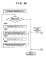
- Figs. 2A and 2B are flowcharts showing a measurement method
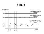
- Fig. 3 is a chart showing transition of the wavelengths of a plurality of light sources
- Fig. 4 is a chart showing a case in which the shape of a surface to be measured falls within the measurement range of a measurement wavelength
- Fig. 5 is a chart showing a case in which the shape of a surface to be measured falls outside the measurement range of the measurement wavelength.
- the measurement apparatus includes a first light source (wavelength-tunable laser) 1, a second light source (fixed-wavelength laser) 2, a third light source (fixed-wavelength laser) 3, and a gas cell 4 serving as a wavelength reference element.
- the wavelength-tunable laser 1 generates the first light containing a scan section in which the wavelength is scanned between the first wavelength ⁇ 1 and the second wavelength ⁇ 2 .
- the fixed-wavelength laser 2 generates the second light having the third wavelength ⁇ 3 .
- the fixed-wavelength laser 3 generates the third light having the fourth wavelength ⁇ 4 .
- the measurement apparatus also includes a polarizing beam splitter 20, a reference surface 6, and first to third detectors 10c to 10a which detect an interference fringe arising from an optical path difference between the reference surface 6 and a surface 7 to be measured.
- the first detector 10c detects the first interference fringe generated upon irradiating the reference surface 6 and the surface 7 to be measured with the first light which has been generated by the wavelength-tunable laser 1 and has a wavelength scanned between the wavelength ⁇ 1 and the second wavelength ⁇ 2 .
- the second detector 10b detects the second interference fringe generated upon irradiating the reference surface 6 and the surface 7 to be measured with the second light of the wavelength ⁇ 3 generated by the fixed-wavelength laser 2.
- the third detector 10a detects the third interference fringe generated upon irradiating the reference surface 6 and the surface 7 to be measured with the third light of the wavelength ⁇ 4 generated by the fixed-wavelength laser 3.
- the measurement apparatus further includes a calculation unit 8 which calculates the absolute distance of the surface 7 to be measured from the reference surface 6.
- the fixed-wavelength lasers 2 and 3 generate the first synthetic wavelength
- the wavelength-tunable laser 1 in which the wavelength is scanned generates the second synthetic wavelength.
- the second synthetic wavelength ⁇ 12 is much longer than the first to fourth wavelengths ⁇ 1 to ⁇ 4 , and has a low measurement precision but a wide measurement range.
- the first synthetic wavelength ⁇ 34 is shorter than the first to fourth wavelengths ⁇ 1 to ⁇ 4 and the second synthetic wavelength ⁇ 12 .
- the first synthetic wavelength ⁇ 34 has a high measurement precision but a narrow measurement range, compared to the first to fourth wavelengths ⁇ 1 to ⁇ 4 and the second synthetic wavelength ⁇ 12 .
- the calculation unit 8 in the embodiment calculates the position and shape of the surface 7 to be measured by using the high-measurement-precision first synthetic wavelength ⁇ 34 as a measurement wavelength which determines a measurement range.
- the shape of a surface to be measured can be obtained by measuring the distance of the surface to be measured from the reference surface and connecting the distances (positions) of respective points on the surface to be measured.
- the interference order of the first synthetic wavelength ⁇ 34 cannot be obtained from phase data of the first synthetic wavelength ⁇ 34 after the time (first time) when the step was detected. Neither the position nor shape of the surface 7 to be measured can be calculated any more.
- the interference order of the first synthetic wavelength ⁇ 34 is determined from that of the second synthetic wavelength ⁇ 12 by connecting the second synthetic wavelength ⁇ 12 equal to or larger than the step, and the first synthetic wavelength ⁇ 34 .
- the measurement apparatus can greatly reduce the wavelength scan amount of the wavelength-tunable laser 1 and ensure a large measurement range. Since the wavelength can be scanned by modulating a laser current, the measurement apparatus quickly measures the absolute distance of the surface 7 to be measured.
- a beam emitted by the wavelength-tunable laser 1 is divided by a beam splitter 5a.
- a beam emitted by the fixed-wavelength laser 2 different in wavelength from the wavelength-tunable laser 1 is incident on a beam splitter 5b, deflected, and then incident on the beam splitter 5a. This beam becomes coaxial with the beam emitted by the wavelength-tunable laser 1, and is divided at the same time.
- a beam emitted by the fixed-wavelength laser 3 different in wavelength from the wavelength-tunable laser 1 and fixed-wavelength laser 2 is incident on and passes through the beam splitter 5b, and then is incident on the beam splitter 5a. This beam becomes coaxial with the beam emitted by the wavelength-tunable laser 1, and is divided at the same time.
- One beam divided by the beam splitter 5a passes through the gas cell 4, and is separated into beams of the wavelength-tunable laser 1, fixed-wavelength laser 2, and fixed-wavelength laser 3 via spectral elements 12a and 12b.
- a detector 13a detects the amount of beam of the wavelength-tunable laser 1
- a detector 13b detects that of beam of the fixed-wavelength laser 2
- a detector 13c detects that of beam of the fixed-wavelength laser 3.
- the wavelength-tunable laser 1, fixed-wavelength laser 2, and fixed-wavelength laser 3 adopt identical DFB (Distributed FeedBack) semiconductor lasers.
- the wavelength-tunable laser 1, fixed-wavelength laser 2, and fixed-wavelength laser 3 are separate lasers.
- a plurality of semiconductor lasers may be integrated on one element, similar to a multi-wavelength light source used in optical communication. This structure is advantageous in cost and dimensions.
- a laser controller 14 controls to stabilize the wavelength of the fixed-wavelength laser 2 to the wavelength ⁇ 3 serving as an absorption line of the gas cell 4 by using a signal from the detector 13b.
- the wavelength is stabilized by adjusting the wavelength of the fixed-wavelength laser 2 by the laser controller 14 to keep the transmission intensity of the detector 13b constant.
- the laser controller 14 modulates an injection current.
- the laser controller 14 controls to stabilize the wavelength of the fixed-wavelength laser 3 to the wavelength ⁇ 4 serving as an absorption line of the gas cell 4 by using a signal from the detector 13c.
- the wavelength-tunable laser 1 is stabilized at the transmission spectrum of the gas cell 4 that corresponds to the wavelength ⁇ 1 . After the stabilization control is canceled and the wavelength is scanned to the wavelength ⁇ 2 by current modulation, the wavelength is stabilized at the wavelength ⁇ 2 . This also applies to wavelength scanning from the wavelength ⁇ 2 to the wavelength ⁇ 1 . In this manner, the wavelength-tunable laser 1 can be stabilized at either of at least two reference wavelengths ⁇ 1 and ⁇ 2 , and scans the wavelength between ⁇ 1 and ⁇ 2 periodically at high speed.
- Fig. 3 shows temporal changes of the wavelengths of the wavelength-tunable laser 1, fixed-wavelength laser 2, and fixed-wavelength laser 3 in the embodiment.
- the embodiment guarantees the wavelength precision using only the gas cell 4. However, an etalon may be used for wavelength guarantee as long as the following precision conditions for order determination are satisfied. Both the gas cell 4 and etalon may be employed.
- the other beam divided by the beam splitter 5a is further divided into the first and second beams by a polarizing beam splitter (first polarizing beam splitter) 16.
- the first beam propagates up to a polarizing beam splitter (second polarizing beam splitter) 17.
- the second beam is incident on a modulator (wavelength shifter) 11 which modulates the second beam at a predetermined frequency.
- the wavelength shifter 11 applies a predetermined amount of frequency shift dv to incident wavelengths by an acoustooptic element (not shown) for beams output from the wavelength-tunable laser 1 and fixed-wavelength lasers 2 and 3.
- a beam emerging from the wavelength shifter 11 propagates up to the polarizing beam splitter 17.
- the first and second beams are combined by the polarizing beam splitter 17 to travel along a common optical path again. Then, a beam splitter 18 branches the combined beam into two. One branched beam passes through a polarizer 27 and is incident on a spectral element 19.
- the spectral element 19 separates the coaxially incident beams of the wavelength-tunable laser 1, fixed-wavelength laser 2, and fixed-wavelength laser 3.
- an array waveguide diffraction grating is used.
- a prism or bulk diffraction grating is also available.
- the first detector 10c detects a beat signal corresponding to the frequency difference between these two beams.
- the second detector 10b detects a beat signal corresponding to the frequency difference between these two beams.
- the third detector 10a detects a beat signal corresponding to the frequency difference between these two beams.
- an interference signal is obtained by extracting the common polarized component of the first and second beams by a polarizer. Interference signals detected by the first to third detectors 10c to 10a via the spectral element 19 will be referred to as reference signals.
- the other beam branched by the beam splitter 18 is incident on an interferometer 100 which measures a distance.
- a collimator lens 21 collimates the beam incident on the interferometer 100 into parallel light.
- the polarizing beam splitter 20 in the interferometer 100 is arranged to transmit the first beam and reflect the second beam.
- the second beam reflected by the polarizing beam splitter 20 is changed into circularly polarized light by a ⁇ /4 plate 22, reflected by the reference surface 6 serving as a cube corner reflector, and changed into reverse circularly polarized light.
- the second beam passes through the ⁇ /4 plate 22 again, is changed into linearly polarized light having a polarization plane rotated by 90° from that upon incidence, and then incident on the polarizing beam splitter 20 again.
- the second beam passes through the polarizing beam splitter 20 and then through a polarizer 28, is condensed by a condenser lens 25, and incident on a spectral element 26.
- the first beam having passed through the polarizing beam splitter 20 is changed into circularly polarized light by a ⁇ /4 plate 23, and is condensed on the surface 7 to be measured as a convergent beam via a condenser lens 24.
- the first beam is reflected by the surface 7 to be measured, and changed into reverse circularly polarized light.
- the first beam passes through the ⁇ /4 plate 23 again, is changed into linearly polarized light having a polarization plane rotated by 90° from that upon incidence, and then incident on the polarizing beam splitter 20 again.
- the first beam is reflected by the polarizing beam splitter 20, condensed by the condenser lens 25, and incident on the spectral element 26.
- a beam reflected by the reference surface 6 will be referred to as a reference beam, and a beam reflected by the surface 7 to be measured will be referred to as a measurement beam.
- the reference beam and measurement beam can have the same intensity.
- the intensity can be adjusted by rotating the polarizer 28 by a rotation mechanism (not shown).
- the intensity of the reference beam or measurement beam may be adjusted using an ND filter or the like (not shown).
- the first detector 10c detects the interference signal of the reference beam and measurement beam having the wavelength ⁇ 1 that have been incident on the spectral element 26.
- the second detector 10b detects the interference signal of the reference beam and measurement beam having the wavelength ⁇ 3 .
- the third detector 10a detects the interference signal of the reference beam and measurement beam having the wavelength ⁇ 4 .
- the interference signals detected by the first to third detectors 10c to 10a via the spectral element 26 will be referred to as measurement signals.
- the measurement signal serves as a beat signal corresponding to the frequency difference between these two beams, similar to the reference signal.
- the phase of the interference signal is different from that of the reference signal owing to an optical path length difference between measurement light and reference light.
- the polarizing beam splitter 20 capable of dividing a beam into polarized components is used as an element for dividing a beam from the interferometer 100.
- the effect of using the polarizing beam splitter 20 beams reflected by the reference surface 6 and the surface 7 to be measured can be separated by polarization.
- heterodyne detection becomes possible between the surface 7 to be measured and the reference surface 6 by slightly adding a frequency shift difference between two orthogonal polarizations, thereby implementing high-precision phase measurement.
- the embodiment is configured as an interferometer which measures the distance of the surface 7 to be measured.
- the present invention is also applicable to shape measurement to obtain surface shape information of the surface 7 to be measured by placing the surface 7 to be measured on a stable drivable in the X-Y plane.
- a galvano-mirror may be interposed between the interferometer 100 and the surface 7 to be measured.
- the calculation unit 8 includes at least a memory 81, first calculation unit 82, and second calculation unit 83.
- the memory 81 stores the phase measurement results of the light sources 1 to 3.
- the first calculation unit 82 receives a reference signal and measurement signal, and calculates the absolute distance between the surface 7 to be measured and the reference surface 6.
- the second calculation unit 83 determines the interference order later.
- the calculation unit 8 is connected to the laser controller 14, and also controls the wavelength of the wavelength-tunable laser 1 according to a measurement sequence.
- the calculation unit 8 sets a calculation flag to 0.
- the calculation flag is a determination flag which becomes 1 when the height difference on the surface 7 to be measured exceeds half of ⁇ 34 at an interval between the start time t' 0 of a wavelength scan and the end time t 1 of the next wavelength scan; otherwise, 0.
- the function of this calculation flag will be described later.
- the measurement sequence is roughly divided into two loops. One is a wavelength control loop, and the other is a measurement loop.
- the wavelength control loop as shown in Fig. 3 , it is repeated to scan the wavelength-tunable laser 1 between the reference wavelengths ⁇ 1 and ⁇ 2 , and control it to stabilize at either reference wavelength.
- the calculation unit 8 transmits, to step S104, a flag representing the completion of the wavelength scan. Upon receiving this flag, the calculation unit 8 determines in step S104 whether the wavelength scan has been completed.
- the measurement loop will be described.
- the phase is repetitively measured at the scanned wavelength and the third and fourth reference wavelengths ⁇ 3 and ⁇ 4 of the fixed-wavelength lasers 2 and 3.
- Phase measurement between the times to and t 1 will be exemplified.
- the first to third detectors 10c to 10a measure phases at the third reference wavelength ⁇ 3 , fourth reference wavelength ⁇ 4 , and second reference wavelength ⁇ 2 .
- Phase measurement is measurement of a phase difference between a measurement signal and a reference signal.
- the calculation unit 8 measures the phases of the reference signal and measurement signal using a phase meter, and calculates a difference between them, obtaining a phase difference.
- the memory 81 in Fig. 1 stores the obtained phase difference.
- the first synthetic wavelength ⁇ 34 is much shorter than the second synthetic wavelength ⁇ 12 of ⁇ 1 and ⁇ 2 , and can measure the distance and shape of the surface 7 to be measured at the highest precision.
- the embodiment prepares the fixed-wavelength laser 2 having the wavelength ⁇ 3 and the fixed-wavelength laser 3 having the wavelength ⁇ 4 in order to obtain a synthetic wavelength of short wavelengths capable of measuring the distance and shape of the surface 7 to be measured at the highest precision.
- the wavelength ⁇ 3 of the fixed-wavelength laser 2 is a wavelength capable of measuring the distance and shape of the surface 7 to be measured at high precision
- the fixed-wavelength laser 3 may be omitted.
- the calculation unit 8 stores, in the memory 81, the histories of the phase difference ⁇ 34 (t) of the synthetic wavelength ⁇ 34 and the phase difference ⁇ a (t 0 ) of the tunable laser which have been measured and calculated in steps S101, S102, and S201.
- the calculation unit 8 determines, based on the wavelength scan completion flags transmitted in steps S402 and S404 of the measurement loop, whether the wavelength scan has been completed. If the wavelength scan has not been completed, the process advances to step S105; if it has been completed, to step S110.
- a threshold is set in advance for the change amount of light amount variations on a light amount monitor (not shown in Figs. 2A and 2B ). When the light amount exceeds the threshold, it is determined that the condition of equation (4) is not satisfied any more. If the schematic shape of the surface 7 to be measured is known in advance, the presence of a step may be determined based on the shape information.
- the calculation flag is 0 in step S106
- the calculation unit 8 stores the measurement time t a of the step on the surface 7 to be measured in the memory 81 in step S109.
- the calculation unit 8 changes the calculation flag to 1. Until the next wavelength scan is completed from this stage, neither the interference order N 34 nor the absolute measured distance D(t) is calculated, and the process returns to the measurement loop. If the calculation flag is 1 in step S106, the process directly returns to the measurement loop.
- the phase of the wavelength-tunable laser 1 at the time t 1 is calculated by adding, to the phase difference ⁇ a (t 0 ) using light from the wavelength-tunable laser 1 at the time to, a relative displacement ⁇ D(t 0 ⁇ t 1 ) calculated from a continuous phase difference change between t 0 and t 1 using the high-precision first synthetic wavelength ⁇ 34 .
- the phase difference ⁇ ' a (t 1 ) using light from the wavelength-tunable laser 1 at the time t 1 serves as the correction value of the phase difference ⁇ a (t 1 ) calculated based on equation (7).
- step S112 the calculation unit 8 calculates the interference order N 34 (t 1 ) of measurement using the synthetic wavelength ⁇ 34 .
- step S112 the calculation unit 8 calculates the interference order M 23 (t 1 ) of measurement using the synthetic wavelength ⁇ 234 of the wavelength ⁇ 2 and synthetic wavelength ⁇ 34 .
- D(t 1 ) is given by equations (12) and (13) using the synthetic wavelengths ⁇ 34 and ⁇ 234 :
- D t 1 ⁇ 34 / 2 ⁇ N 34 t 1 + ⁇ 34 t 1 / 2 ⁇ ⁇
- D t 1 ⁇ 234 / 2 ⁇ M 23 t 1 + ⁇ 34 t 1 - ⁇ a t 1 / 2 ⁇ ⁇
- the calculation unit 8 calculates M 23 (t 1 ) using equation (15) from M 12 (t 1 ) calculated in step S111, and N 34 (t 1 ) using equation (14) from calculated M 23 (t 1 ).
- the three synthetic wavelengths ⁇ 34 , ⁇ 234 , and ⁇ 12 have a relation of ⁇ 34 ⁇ ⁇ 234 ⁇ ⁇ 12 .
- the longest wavelength ⁇ 12 has the largest reference wavelength, can continuously measure the surface 7 to be measured even if a step exists on the surface 7 to be measured, but is poor in measurement precision. If the shortest synthetic wavelength ⁇ 34 is used, the distance and shape of the surface 7 to be measured can be measured at the highest precision, but the measurement range is small.
- the interference order N 34 of the synthetic wavelength ⁇ 34 becomes discontinuous when a step appears.
- step S113 A case in which the calculation flag is 0 in step S113, that is, the height difference on the surface 7 to be measured is equal to or smaller than half of ⁇ 34 at an interval between the start time t' 0 of the previous wavelength scan and t 1 will be described.
- step S117 the calculation unit 8 updates the interference order N 34 recorded in step S107 to the interference order N 34 (t 1 ) calculated in step S112. Thereafter, the process returns to the calculation loop.
- step S113 A case in which the calculation flag is 1 in step S113, that is, the height difference on the surface 7 to be measured is larger than half of ⁇ 34 at an interval between the start time t' 0 of the previous wavelength scan and t 1 will be described. Since phase connection is impossible from the first time t a stored in step S109 to the second time t 1 , the absolute distance D(t) after the first time is not calculated.
- the calculation unit 8 returns the calculation flag to 0 in step S116, and in step S117, updates the interference order N 34 recorded in step S107 to the interference order N 34 calculated in step S112. The process then returns to the calculation loop.
- the second calculation unit 83 performs the calculation in steps S114 and S115 separately from the measurement loop processed by the first calculation unit 82, thereby preventing generation of a delay in the measurement loop time.
- the embodiment can reduce the wavelength scan amount, and provide a high-speed measurement apparatus having a wide measurement range with a simple arrangement.
- the embodiment has described a measure against the problem that the interference order becomes unknown when the height difference on a surface to be measured exceeds the synthetic wavelength ⁇ 34 .
- the same measure can also apply to a case in which the interference order becomes unknown when light from the light source is temporarily cut off.
- the heterodyne interferometer has been described, but a homodyne interferometer is also available.
Landscapes
- Physics & Mathematics (AREA)
- General Physics & Mathematics (AREA)
- Length Measuring Devices By Optical Means (AREA)
- Instruments For Measurement Of Length By Optical Means (AREA)
Applications Claiming Priority (1)
| Application Number | Priority Date | Filing Date | Title |
|---|---|---|---|
| JP2011224306A JP2013083581A (ja) | 2011-10-11 | 2011-10-11 | 計測装置 |
Publications (1)
| Publication Number | Publication Date |
|---|---|
| EP2581700A1 true EP2581700A1 (fr) | 2013-04-17 |
Family
ID=47040507
Family Applications (1)
| Application Number | Title | Priority Date | Filing Date |
|---|---|---|---|
| EP12006482.9A Withdrawn EP2581700A1 (fr) | 2011-10-11 | 2012-09-14 | Mesure de distance absolue avec un interféromètre à longueurs d'ondes multiples |
Country Status (3)
| Country | Link |
|---|---|
| US (1) | US20130088722A1 (fr) |
| EP (1) | EP2581700A1 (fr) |
| JP (1) | JP2013083581A (fr) |
Families Citing this family (7)
| Publication number | Priority date | Publication date | Assignee | Title |
|---|---|---|---|---|
| US9025141B1 (en) * | 2013-11-08 | 2015-05-05 | The Boeing Company | Position determination using synthetic wave laser ranging |
| US20150131078A1 (en) * | 2013-11-08 | 2015-05-14 | The Boeing Company | Synthetic wave laser ranging sensors and methods |
| US20180283845A1 (en) * | 2017-03-31 | 2018-10-04 | Intel Corporation | Wavelength modulatable interferometer |
| DE102017210991A1 (de) * | 2017-06-28 | 2018-07-12 | Carl Zeiss Smt Gmbh | Lichtquelle für ein Heterodyninterferometer |
| DE102017220408A1 (de) * | 2017-11-15 | 2018-12-13 | Carl Zeiss Smt Gmbh | Optisches System für die Mikrolithographie, sowie Verfahren zur Positionsbestimmung |
| DE102017220407A1 (de) * | 2017-11-15 | 2018-12-13 | Carl Zeiss Smt Gmbh | Optisches System für die Mikrolithographie, sowie Verfahren zur Positionsbestimmung |
| CN111609798B (zh) * | 2020-05-12 | 2021-04-16 | 浙江理工大学 | 锁至动态边带的可变合成波长绝对距离测量装置与方法 |
Citations (3)
| Publication number | Priority date | Publication date | Assignee | Title |
|---|---|---|---|---|
| JPH0552540A (ja) | 1991-02-08 | 1993-03-02 | Hughes Aircraft Co | 干渉計レーザ表面粗さ計 |
| JPH10281738A (ja) | 1997-04-08 | 1998-10-23 | Fuji Xerox Co Ltd | 干渉計測方法および干渉計測装置 |
| US20110211198A1 (en) * | 2010-03-01 | 2011-09-01 | Canon Kabushiki Kaisha | Lightwave interference measurement apparatus that calculates absolute distance using lightwave interference |
-
2011
- 2011-10-11 JP JP2011224306A patent/JP2013083581A/ja not_active Withdrawn
-
2012
- 2012-09-12 US US13/611,816 patent/US20130088722A1/en not_active Abandoned
- 2012-09-14 EP EP12006482.9A patent/EP2581700A1/fr not_active Withdrawn
Patent Citations (3)
| Publication number | Priority date | Publication date | Assignee | Title |
|---|---|---|---|---|
| JPH0552540A (ja) | 1991-02-08 | 1993-03-02 | Hughes Aircraft Co | 干渉計レーザ表面粗さ計 |
| JPH10281738A (ja) | 1997-04-08 | 1998-10-23 | Fuji Xerox Co Ltd | 干渉計測方法および干渉計測装置 |
| US20110211198A1 (en) * | 2010-03-01 | 2011-09-01 | Canon Kabushiki Kaisha | Lightwave interference measurement apparatus that calculates absolute distance using lightwave interference |
Non-Patent Citations (3)
| Title |
|---|
| KONSTANTINOS FALAGGIS ET AL: "<title>A hybrid technique for ultra-high dynamic range interferometry</title>", PROCEEDINGS OF SPIE, vol. 7063, 10 August 2008 (2008-08-10), pages 70630X - 70630X-8, XP055050882, ISSN: 0277-786X, DOI: 10.1117/12.795293 * |
| R DÄNDLIKER ET AL: "Distance measurement by multiple-wavelength interferometry", JOURNAL OF OPTICS, vol. 29, no. 3, 1 June 1998 (1998-06-01), pages 105 - 114, XP055050854, ISSN: 0150-536X, DOI: 10.1088/0150-536X/29/3/002 * |
| U. VRY; F. FERCHER: "High-order statistical properties of speckle fields and their application to rough-surface interferometry", J. OPT. SOC. AM. A, vol. 3, no. 7, 1986, pages 988 - 1000, XP055055754, DOI: doi:10.1364/JOSAA.3.000988 |
Also Published As
| Publication number | Publication date |
|---|---|
| US20130088722A1 (en) | 2013-04-11 |
| JP2013083581A (ja) | 2013-05-09 |
Similar Documents
| Publication | Publication Date | Title |
|---|---|---|
| EP2066998B1 (fr) | Procédé et dispositif pour générer une longueur d'onde synthétique | |
| EP2581700A1 (fr) | Mesure de distance absolue avec un interféromètre à longueurs d'ondes multiples | |
| US8363226B2 (en) | Optical interference measuring apparatus | |
| US7898669B2 (en) | Absolute distance measurement method and system using optical frequency generator | |
| Xiaoli et al. | High-accuracy absolute distance measurement by means of wavelength scanning heterodyne interferometry | |
| JP2553276B2 (ja) | 3波長光学測定装置及び方法 | |
| JPH0830651B2 (ja) | 干渉計レーザ表面粗さ計 | |
| Dändliker et al. | Distance measurement by multiple-wavelength interferometry | |
| EP2634525A1 (fr) | Interféromètre à plusieurs longueurs d'onde pour la mesure des distances absolues | |
| US10041782B2 (en) | Apparatus for measuring length of optical resonant cavity | |
| JP2010261890A (ja) | 光波干渉計測装置 | |
| Barwood et al. | High-accuracy length metrology using multiple-stage swept-frequency interferometry with laser diodes | |
| JP6264547B2 (ja) | 光信号生成装置、距離測定装置、分光特性測定装置、周波数特性測定装置及び光信号生成方法 | |
| JP5421013B2 (ja) | 位置決め装置及び位置決め方法 | |
| JP6628030B2 (ja) | 距離測定装置及びその方法 | |
| US20140160490A1 (en) | Interference measuring apparatus and interference measuring method | |
| JP5654837B2 (ja) | 変位測定装置 | |
| JP6503618B2 (ja) | 距離測定装置及びその方法 | |
| JP7451704B2 (ja) | レーザ周波数シフトによる高速位相シフト干渉法 | |
| Kajima et al. | Super-heterodyne laser interferometer using femtosecond frequency comb for linear encoder calibration system | |
| Li et al. | Distance Measurement Based on a Coherently Synthesized Two-color EO Comb towards High-accuracy Air-refractive Index Self-Correction | |
| JPH11274643A (ja) | 可変波長半導体レーザ光源 | |
| Kim et al. | Absolute Distance Measurements Using the Frequency Comb of a Femtosecond Pulse Laser | |
| Kajima et al. | Self-zooming stable stage with sub-nm resolution using femtosecond frequency comb |
Legal Events
| Date | Code | Title | Description |
|---|---|---|---|
| PUAI | Public reference made under article 153(3) epc to a published international application that has entered the european phase |
Free format text: ORIGINAL CODE: 0009012 |
|
| AK | Designated contracting states |
Kind code of ref document: A1 Designated state(s): AL AT BE BG CH CY CZ DE DK EE ES FI FR GB GR HR HU IE IS IT LI LT LU LV MC MK MT NL NO PL PT RO RS SE SI SK SM TR |
|
| AX | Request for extension of the european patent |
Extension state: BA ME |
|
| 17P | Request for examination filed |
Effective date: 20131017 |
|
| RBV | Designated contracting states (corrected) |
Designated state(s): AL AT BE BG CH CY CZ DE DK EE ES FI FR GB GR HR HU IE IS IT LI LT LU LV MC MK MT NL NO PL PT RO RS SE SI SK SM TR |
|
| STAA | Information on the status of an ep patent application or granted ep patent |
Free format text: STATUS: THE APPLICATION HAS BEEN WITHDRAWN |
|
| 18W | Application withdrawn |
Effective date: 20150529 |