EP2581326A1 - Foliensack als Innenhülle für einen Stahltank - Google Patents
Foliensack als Innenhülle für einen Stahltank Download PDFInfo
- Publication number
- EP2581326A1 EP2581326A1 EP11184782.8A EP11184782A EP2581326A1 EP 2581326 A1 EP2581326 A1 EP 2581326A1 EP 11184782 A EP11184782 A EP 11184782A EP 2581326 A1 EP2581326 A1 EP 2581326A1
- Authority
- EP
- European Patent Office
- Prior art keywords
- foil bag
- magnets
- tank
- bag
- sack
- Prior art date
- Legal status (The legal status is an assumption and is not a legal conclusion. Google has not performed a legal analysis and makes no representation as to the accuracy of the status listed.)
- Granted
Links
Images
Classifications
-
- B—PERFORMING OPERATIONS; TRANSPORTING
- B65—CONVEYING; PACKING; STORING; HANDLING THIN OR FILAMENTARY MATERIAL
- B65D—CONTAINERS FOR STORAGE OR TRANSPORT OF ARTICLES OR MATERIALS, e.g. BAGS, BARRELS, BOTTLES, BOXES, CANS, CARTONS, CRATES, DRUMS, JARS, TANKS, HOPPERS, FORWARDING CONTAINERS; ACCESSORIES, CLOSURES, OR FITTINGS THEREFOR; PACKAGING ELEMENTS; PACKAGES
- B65D90/00—Component parts, details or accessories for large containers
- B65D90/02—Wall construction
- B65D90/04—Linings
- B65D90/046—Flexible liners, e.g. loosely positioned in the container
-
- B—PERFORMING OPERATIONS; TRANSPORTING
- B65—CONVEYING; PACKING; STORING; HANDLING THIN OR FILAMENTARY MATERIAL
- B65D—CONTAINERS FOR STORAGE OR TRANSPORT OF ARTICLES OR MATERIALS, e.g. BAGS, BARRELS, BOTTLES, BOXES, CANS, CARTONS, CRATES, DRUMS, JARS, TANKS, HOPPERS, FORWARDING CONTAINERS; ACCESSORIES, CLOSURES, OR FITTINGS THEREFOR; PACKAGING ELEMENTS; PACKAGES
- B65D2313/00—Connecting or fastening means
- B65D2313/04—Connecting or fastening means of magnetic type
-
- B—PERFORMING OPERATIONS; TRANSPORTING
- B65—CONVEYING; PACKING; STORING; HANDLING THIN OR FILAMENTARY MATERIAL
- B65D—CONTAINERS FOR STORAGE OR TRANSPORT OF ARTICLES OR MATERIALS, e.g. BAGS, BARRELS, BOTTLES, BOXES, CANS, CARTONS, CRATES, DRUMS, JARS, TANKS, HOPPERS, FORWARDING CONTAINERS; ACCESSORIES, CLOSURES, OR FITTINGS THEREFOR; PACKAGING ELEMENTS; PACKAGES
- B65D2590/00—Component parts, details or accessories for large containers
- B65D2590/02—Wall construction
- B65D2590/04—Linings
- B65D2590/043—Flexible liners
- B65D2590/046—Bladders
Definitions
- the present invention relates to a foil bag as an inner shell for a tank, as well as a tank lined with it.
- a PVC tank inner shell serves to make double-walled and environmentally safe storage tanks for liquid media that fall under a hazard class and to protect tanks against corrosion.
- the inner shell is placed in the tank and inflated.
- a monitoring space is created between the tank wall and the inner shell.
- the interstitial space is evacuated, thereby securing the inner shell to the tank wall. This vacuum is permanently held and monitored with a leak detector.
- the tank system is considered double-walled and meets the legal requirements for the storage of media that fall under a hazard class, such as water pollutants and flammable liquids.
- the PVC tank inner shell serves only to store the rainwater and to protect the tank from corrosion.
- the space between the tank wall and the inner shell is evacuated to keep the inner shell against the tank wall. If such a rainwater tank on a vacuum leak detector is dispensed with, the gap must be evacuated again at certain intervals.
- the film bag is magnetically attached to the tank wall to keep the film bag without negative pressure in the tank.
- magnets are attached to the film bag, which adhere to the tank wall.
- the installation in the tank is carried out as in the prior art described above, but without complete fleece lining and without negative pressure.
- the magnets can be attached to the foil bag in any manner, for example, welded into the foil bag or adhered to the foil bag.
- the magnets are particularly preferably provided at least in the ceiling area of the film bag, advantageously at least in the upper half or in the two upper thirds of the foil bag. In the lower third of the film bag is always on the tank wall, so that no magnets are required here.
- the invention also relates, in a further aspect, to a tank having the foil bag formed as above as the inner shell, the magnets of the foil bag adhering to the tank wall.
- the positioning of the magnets on the tank wall takes place automatically when inflating the inner shell in the tank. If necessary, the position of the magnets or the inner shell must be manually corrected after inflation manually.
- the magnet-affixed film bag provides an advantageous alternative to conventional internal coating of steel tanks to protect them from corrosion, and allows cost-effective conversion of steel tanks for rainwater harvesting. Unlike conventional, according to the invention neither a complete nonwoven lining of the tank nor a suction line including associated connections are necessary.
- the magnetic attachment also allows easy and quick installation and disassembly of the foil bag.
- a fleece lining may be installed between the bottom of the tank and the foil bag, which serves as a step protection.
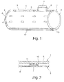
- Fig. 1 shows a horizontal cylindrical steel tank 1 (eg length 4 m, diameter 1.60 m) with a top-side tank opening 2.
- the steel tank 1 is lined with an inner shell in the form of a PVC film bag 3 , which introduced through the tank opening 2 into the tank interior was and is fixed by means of magnets 4 on the tank wall, ie on the tank shell side 5 and on the two tank end faces 6 .
- the magnets 4 may be, for example, NdFeB round magnets with a diameter of 32 mm and a thickness of 7 mm.
- the foil bag 3 is cylindrically prefabricated in accordance with the steel tank 1, so that the bag opening 7 is provided in the lateral surface 8 of the foil bag 3.
- the magnets 4 are provided both on the upper cylinder jacket half and on the two cylinder end faces 9 of the film bag 3.
- the magnets 4 are mounted on the lateral surface 8 from the vertex to the lower third of the foil bag 3 at a distance of about 1m to the length and the circumference.
- the foil bag 3 has no magnets, since here the foil bag 3 always bears against the tank wall.
- three magnets 4 are vertically one above the other, namely, top, middle, bottom, attached.
- the magnets 4 are, as in Fig. 2 shown on the outside of the foil bag 3 arranged in closed plastic bags 10 and welded therein.
- the magnets 4 are placed on the outside of the foil bag 3 and placed over each a piece of film 11 , which is then welded to the edge of the film bag 3 to the film pocket 10.
- the magnets 4 could also be glued to the foil bag 3 on the inside or outside.
Landscapes
- Engineering & Computer Science (AREA)
- Mechanical Engineering (AREA)
- Details Of Rigid Or Semi-Rigid Containers (AREA)
Abstract
Description
- Die vorliegende Erfindung betrifft einen Foliensack als Innenhülle für einen Tank, sowie auch einen damit ausgekleideten Tank.
- Eine PVC-Tankinnenhülle dient dazu, Tanks für die Lagerung von flüssigen Medien, die unter eine Gefährdungsklasse fallen, doppelwandig und umweltsicher zu machen und Tanks vor Korrosion zu schützen. Die Innenhülle wird in den Tank eingebracht und aufgeblasen. Durch Anbringen einer druckbeständigen Vliesauskleidung an der Tankwand wird zwischen Tankwand und Innenhülle ein Überwachungsraum geschaffen. Nachdem die Innenhülle aufgeblasen worden ist, wird der Überwachungsraum evakuiert und dadurch die Innenhülle an der Tankwand befestigt. Dieses Vakuum wird mit einem Leckanzeigegerät dauerhaft gehalten und überwacht. Dadurch gilt die Tankanlage als doppelwandig und erfüllt die gesetzlichen Vorgaben für die Lagerung von Medien, die unter eine Gefährdungsklasse fallen, wie wassergefährdende Stoffe und brennbare Flüssigkeiten.
- Für die Lagerung von Regenwasser oder von anderen flüssigen Medien, die keine Gefährdungsklasse haben, gelten keine gesetzlichen Vorgaben und ist daher keine überwachte Doppelwandigkeit des Tanks notwendig. Bei Lagerung von Regenwasser (kein Trinkwasser) dient die PVC-Tankinnenhülle dient lediglich dazu, das Regenwasser zu lagern und den Tank vor Korrosion zu schützen. Der zwischen Tankwand und Innenhülle befindliche Zwischenraum wird evakuiert, um die Innenhülle an der Tankwand zu halten. Wenn bei solchen Regenwassertanks auf ein Unterdruck-Leckanzeigegerät verzichtet wird, muss der Zwischenraum in gewissen Zeitabständen erneut evakuiert werden.
- Demgegenüber ist es die Aufgabe der vorliegenden Erfindung, einen einfacher und schneller montierbaren Foliensack für einen Tank bereitzustellen.
- Diese Aufgabe wird erfindungsgemäß dadurch gelöst, dass am Foliensack Magnete befestigt sind.
- Erfindungsgemäß wird der Foliensack an der Tankwand magnetbefestigt, um den Foliensack ohne Unterdruck im Tank zu halten. Dazu sind am Foliensack Magnete angebracht, die an der Tankwand haften. Der Einbau in den Tank erfolgt wie bei dem oben beschriebenen Stand der Technik, jedoch ohne komplette Vliesauskleidung und ohne Unterdruck.
- Die Magnete können auf jegliche Art und Weise am Foliensack befestigt sein, beispielsweise in den Foliensack eingeschweißt oder an den Foliensack angeklebt sein.
- Besonders bevorzugt sind bei nach oben ausgerichteter Sacköffnung die Magnete zumindest im Deckenbereich des Foliensacks vorgesehen, vorteilhafterweise zumindest in der oberen Hälfte oder in den beiden oberen Dritteln des Foliensacks. Im unteren Drittel liegt der Foliensack stets an der Tankwand an, so dass hier keine Magnete erforderlich sind.
- Die Erfindung betrifft in einem weiteren Aspekt auch einen Tank mit dem wie oben ausgebildeten Foliensack als Innenhülle, wobei die Magnete des Foliensacks an der Tankwand haften. Die Positionierung der Magnete an der Tankwand erfolgt automatisch beim Aufblasen der Innenhülle im Tank. Gegebenenfalls muss die Position der Magnete bzw. die Innenhülle nach dem Aufblasen manuell noch leicht korrigiert werden. Durch Auskleiden mit dem magnetbefestigten Foliensack können Stahltanks dauerhaft vor Korrosion geschützt und für die Lagerung von Regenwasser genutzt werden. Durch Auskleiden mit dem magnetbefestigten Foliensack können schon korrodierte Tanks oder bisher für andere Flüssigkeiten (z.B. Heizöl) genutzte Tanks saniert und/oder für die Lagerung von anderen Flüssigkeiten (z.B. Regenwasser) genutzt werden.
- Der magnetbefestigte Foliensack stellt eine vorteilhafte Alternative zur herkömmlichen Innenbeschichtung von Stahltanks dar, um diese vor Korrosion zu schützen, und ermöglicht ein kostengünstiges Umrüsten von Stahltanks zur Regenwassernutzung. Anders als herkömmlich sind erfindungsgemäß weder eine komplette Vliesauskleidung des Tanks noch eine Saugleitung samt zugehörigen Anschlüsse notwendig. Die Magnetbefestigung ermöglicht zudem eine einfache und schnelle Montage und auch Demontage des Foliensacks.
- Erforderlichenfalls kann zwischen Tankboden und Foliensack eine Vliesauskleidung verlegt sein, die als Trittschutz dient.
- Weitere Vorteile und vorteilhafte Ausgestaltungen des Gegenstands der Erfindung sind der Beschreibung, der Zeichnung und den Ansprüchen entnehmbar. Ebenso können die vorstehend genannten und die noch weiter aufgeführten Merkmale je für sich oder zu mehreren in beliebigen Kombinationen Verwendung finden. Die gezeigten und beschriebenen Ausführungsformen sind nicht als abschließende Aufzählung zu verstehen, sondern haben vielmehr beispielhaften Charakter für die Schilderung der Erfindung.
- Es zeigen:
- Fig. 1
- einen Stahltank mit dem erfindungsgemäßen magnetbefestigten Foliensack als Innenhülle; und
- Fig. 2
- eine Detailansicht des Foliensacks im Bereich eines der in
Fig. 1 gezeigten, auf den Foliensack eingeschweißten Magnete. -
Fig. 1 zeigt einen horizontal liegenden zylinderförmigen Stahltank 1 (z.B. Länge 4 m, Durchmesser 1,60 m) mit einer oberseitigen Tanköffnung 2. Der Stahltank 1 ist mit einer Innenhülle in Form eines PVC-Foliensacks 3 ausgekleidet, der durch die Tanköffnung 2 in das Tankinnere eingebracht wurde und mittels Magneten 4 an der Tankwand, also an der Tankmantelseite 5 und an den beiden Tankstirnseiten 6, befestigt ist. Die Magnete 4 können beispielsweise NdFeB-Rundmagnete mit einem Durchmesser von 32 mm und einer Dicke von 7 mm sein. - Der Foliensack 3 ist entsprechend dem Stahltank 1 zylinderförmig vorkonfektioniert, so dass die Sacköffnung 7 in der Mantelfläche 8 des Foliensacks 3 vorgesehen ist. Bei nach oben ausgerichteter Sacköffnung 7 sind die Magnete 4 sowohl an der oberen Zylindermantelhälfte als auch an den beiden Zylinderstirnseiten 9 des Foliensacks 3 vorgesehen. Im gezeigten Ausführungsbeispiel sind die Magnete 4 an der Mantelfläche 8 vom Scheitel bis zum unteren Drittel des Foliensacks 3 im Abstand von ca. 1m auf die Länge und den Umfang angebracht. Im unteren Drittel, also im Bodenbereich, weist der Foliensack 3 keine Magnete auf, da hier der Foliensack 3 stets an der Tankwand anliegt. An den beiden Zylinderstirnseiten 9 sind drei Magnete 4 vertikal übereinander, nämlich oben, mittig, unten, angebracht.
- Die Magnete 4 sind, wie in
Fig. 2 gezeigt, außenseitig am Foliensack 3 in geschlossenen Folientaschen 10 angeordnet und darin eingeschweißt. Dazu werden die Magnete 4 auf die Außenseite des Foliensacks 3 gelegt und darüber jeweils ein Folienstück 11 aufgelegt, das dann randseitig mit dem Foliensack 3 zu der Folientasche 10 verschweißt wird. Alternativ könnten die Magnete 4 auch innen- oder außenseitig an den Foliensack 3 angeklebt sein. - Die Positionierung der Magnete 4 an der Tankwand 5, 6 erfolgt automatisch beim Aufblasen des Foliensack 3 im Stahltank 1. Im Bodenbereich, also zwischen Tankboden 12 und Foliensack 3, ist eine Vliesauskleidung 13 verlegt, die als Trittschutz dient.
Claims (10)
- Foliensack (3) als Innenhülle für einen Tank (1),
dadurch gekennzeichnet,
dass am Foliensack (3) Magnete (4) befestigt sind. - Foliensack nach Anspruch 1, dadurch gekennzeichnet, dass bei nach oben ausgerichteter Sacköffnung (7) die Magnete (4) zumindest im Deckenbereich des Foliensacks (3) vorgesehen sind.
- Foliensack nach Anspruch 1 oder 2, dadurch gekennzeichnet, dass bei nach oben ausgerichteter Sacköffnung (7) die Magnete (4) zumindest in der oberen Hälfte, insbesondere zumindest in den beiden oberen Dritteln des Foliensacks (3) vorgesehen sind.
- Foliensack nach einem der vorhergehenden Ansprüche, dadurch gekennzeichnet, dass die Sacköffnung (7) in der Mantelfläche eines zylinderförmig ausgebildeten Foliensacks (3) vorgesehen ist und bei nach oben ausgerichteter Sacköffnung (7) die Magnete (4) an den beiden Zylinderstirnseiten (9) und zumindest an der oberen Zylinderumfangshälfte der Foliensacks (3) vorgesehen sind.
- Foliensack nach einem der vorhergehenden Ansprüche, dadurch gekennzeichnet, dass die Magnete (4) außenseitig am Foliensack (3) angeordnet sind.
- Foliensack nach einem der vorhergehenden Ansprüche, dadurch gekennzeichnet, dass die Magnete (4) in den Foliensack (3) eingeschweißt sind.
- Foliensack nach einem der vorhergehenden Ansprüche, dadurch gekennzeichnet, dass die Magnete (4) jeweils in Folientaschen (10) angeordnet sind, welche am Foliensack (3) angeordnet sind.
- Foliensack nach einem der Ansprüche, dadurch gekennzeichnet, dass die Magnete (4) an den Foliensack (3) angeklebt sind.
- Tank (1) aus ferromagnetischem Material, insbesondere Stahltank, mit einer oberseitigen Tanköffnung (2),
mit einem den Tank (1) innen auskleidenden Foliensack (3) nach einem der vorhergehenden Ansprüche, wobei die Magnete (4) des Foliensacks (3) an der Tankwand (5, 6) haften. - Tank nach Anspruch 9, dadurch gekennzeichnet, dass zwischen Tankboden (12) und Foliensack (3) eine Vliesauskleidung (13) als Trittschutz verlegt ist.
Priority Applications (1)
| Application Number | Priority Date | Filing Date | Title |
|---|---|---|---|
| EP11184782.8A EP2581326B1 (de) | 2011-10-12 | 2011-10-12 | Foliensack als Innenhülle für einen Stahltank |
Applications Claiming Priority (1)
| Application Number | Priority Date | Filing Date | Title |
|---|---|---|---|
| EP11184782.8A EP2581326B1 (de) | 2011-10-12 | 2011-10-12 | Foliensack als Innenhülle für einen Stahltank |
Publications (2)
| Publication Number | Publication Date |
|---|---|
| EP2581326A1 true EP2581326A1 (de) | 2013-04-17 |
| EP2581326B1 EP2581326B1 (de) | 2013-12-18 |
Family
ID=44772909
Family Applications (1)
| Application Number | Title | Priority Date | Filing Date |
|---|---|---|---|
| EP11184782.8A Active EP2581326B1 (de) | 2011-10-12 | 2011-10-12 | Foliensack als Innenhülle für einen Stahltank |
Country Status (1)
| Country | Link |
|---|---|
| EP (1) | EP2581326B1 (de) |
Cited By (2)
| Publication number | Priority date | Publication date | Assignee | Title |
|---|---|---|---|---|
| US9526309B2 (en) * | 2013-04-29 | 2016-12-27 | George-Michael Huyke-Phillips | Magnetized liner for storage and holding bags |
| DE102022104021A1 (de) | 2021-03-19 | 2022-09-22 | W + H Tankschutz Gmbh | Innenauskleidung für einen Tank |
Citations (3)
| Publication number | Priority date | Publication date | Assignee | Title |
|---|---|---|---|---|
| DE2601094A1 (de) * | 1976-01-14 | 1977-07-21 | Mierau Albert | Behaelter fuer die lagerung von fluessigkeiten unter ueberdruck |
| WO2007004216A2 (en) * | 2005-07-04 | 2007-01-11 | Terrasafe Environmental Protection Ltd. | Replaceable tank lining |
| WO2010046790A1 (en) * | 2008-10-23 | 2010-04-29 | Trans Ocean Liquid Technologies (Pty) Ltd | Thermal insulation of shipping containers |
-
2011
- 2011-10-12 EP EP11184782.8A patent/EP2581326B1/de active Active
Patent Citations (3)
| Publication number | Priority date | Publication date | Assignee | Title |
|---|---|---|---|---|
| DE2601094A1 (de) * | 1976-01-14 | 1977-07-21 | Mierau Albert | Behaelter fuer die lagerung von fluessigkeiten unter ueberdruck |
| WO2007004216A2 (en) * | 2005-07-04 | 2007-01-11 | Terrasafe Environmental Protection Ltd. | Replaceable tank lining |
| WO2010046790A1 (en) * | 2008-10-23 | 2010-04-29 | Trans Ocean Liquid Technologies (Pty) Ltd | Thermal insulation of shipping containers |
Cited By (2)
| Publication number | Priority date | Publication date | Assignee | Title |
|---|---|---|---|---|
| US9526309B2 (en) * | 2013-04-29 | 2016-12-27 | George-Michael Huyke-Phillips | Magnetized liner for storage and holding bags |
| DE102022104021A1 (de) | 2021-03-19 | 2022-09-22 | W + H Tankschutz Gmbh | Innenauskleidung für einen Tank |
Also Published As
| Publication number | Publication date |
|---|---|
| EP2581326B1 (de) | 2013-12-18 |
Similar Documents
| Publication | Publication Date | Title |
|---|---|---|
| EP2581326B1 (de) | Foliensack als Innenhülle für einen Stahltank | |
| DE102017002876A1 (de) | Kunststoff-Innenbehälter mit Inliner | |
| DE102012105539A1 (de) | Wärmenutzungsanlage | |
| DE202012102341U1 (de) | Flüssigkeitstank mit magnetbefestigtem Foliensack als Innenhülle | |
| DE102015120730A1 (de) | Magnetisch-induktives Durchflussmessgerät und Anordnung umfassend eine Rohrleitung und ein magnetisch-induktives Durchflussmessgerät | |
| EP2734452B1 (de) | Behälter für flüssige chemikalien | |
| EP2690036B1 (de) | Verfahren zum mannlosen Einbauen einer Tankinnenauskleidung in einen Tank und Tankinnenauskleidung | |
| DE102012205133A1 (de) | Behälter, insbesondere Gär- oder Faulbehälter | |
| DE102017113746B3 (de) | Mobiler Behälter für Trinkwasser | |
| EP2728090B1 (de) | Montage- und Reparatureinrichtung | |
| DE102011001987A1 (de) | Verfahren und Vorrichtung zum Einschließen eines Bohrlochs | |
| EP2587242B1 (de) | Leckagesonde für einen doppelwandigen Tank | |
| DE102015001388A1 (de) | Vorrichtung zur Gewinnung von Tiefenerdwärme über einen "erdbewegungswiderstehenden Tiefenerdwärmekollektor" mit gewichtsreduzierter Erdwärmeabtransportierleitung durch Vorspannung | |
| DE102015011481A1 (de) | Behälter aus Kunststoff mit mindestens einem Hohlkörper | |
| DE202012011477U1 (de) | Mannloser Einbau Tankinnenhülle | |
| AT272966B (de) | Lagerbehälter für Flüssigkeiten, insbesondere für Heizöl | |
| WO1997043203A2 (de) | Flüssigkeitsbehälter | |
| DE202014009044U1 (de) | Tankverschluss | |
| DE102011016884B4 (de) | Transport- und Ausgabebehälter für Flüssigkeiten | |
| DE4003434C2 (de) | ||
| CN204957413U (zh) | 一种便于下料的下料斗 | |
| DE202010011178U1 (de) | Abdeckung für unterirdische Behälter | |
| DE202011005352U1 (de) | Druckkontrollierbares Doppelwandsystem mit Durchbruch und optionaler Rohranbindung | |
| EP3208394A1 (de) | Tauchbogen, schlammsammler sowie verfahren zur handhabung des tauchbogens | |
| DE1963426B2 (de) | Behaelter fuer heizoel od.dgl |
Legal Events
| Date | Code | Title | Description |
|---|---|---|---|
| PUAI | Public reference made under article 153(3) epc to a published international application that has entered the european phase |
Free format text: ORIGINAL CODE: 0009012 |
|
| AK | Designated contracting states |
Kind code of ref document: A1 Designated state(s): AL AT BE BG CH CY CZ DE DK EE ES FI FR GB GR HR HU IE IS IT LI LT LU LV MC MK MT NL NO PL PT RO RS SE SI SK SM TR |
|
| AX | Request for extension of the european patent |
Extension state: BA ME |
|
| 17P | Request for examination filed |
Effective date: 20130405 |
|
| 17Q | First examination report despatched |
Effective date: 20130514 |
|
| GRAP | Despatch of communication of intention to grant a patent |
Free format text: ORIGINAL CODE: EPIDOSNIGR1 |
|
| INTG | Intention to grant announced |
Effective date: 20130918 |
|
| GRAS | Grant fee paid |
Free format text: ORIGINAL CODE: EPIDOSNIGR3 |
|
| GRAA | (expected) grant |
Free format text: ORIGINAL CODE: 0009210 |
|
| AK | Designated contracting states |
Kind code of ref document: B1 Designated state(s): AL AT BE BG CH CY CZ DE DK EE ES FI FR GB GR HR HU IE IS IT LI LT LU LV MC MK MT NL NO PL PT RO RS SE SI SK SM TR |
|
| REG | Reference to a national code |
Ref country code: GB Ref legal event code: FG4D Free format text: NOT ENGLISH |
|
| REG | Reference to a national code |
Ref country code: CH Ref legal event code: EP Ref country code: CH Ref legal event code: NV Representative=s name: RIEDERER HASLER AND PARTNER PATENTANWAELTE AG, LI |
|
| REG | Reference to a national code |
Ref country code: AT Ref legal event code: REF Ref document number: 645523 Country of ref document: AT Kind code of ref document: T Effective date: 20140115 |
|
| REG | Reference to a national code |
Ref country code: IE Ref legal event code: FG4D Free format text: LANGUAGE OF EP DOCUMENT: GERMAN |
|
| REG | Reference to a national code |
Ref country code: DE Ref legal event code: R096 Ref document number: 502011001839 Country of ref document: DE Effective date: 20140213 |
|
| REG | Reference to a national code |
Ref country code: NL Ref legal event code: VDEP Effective date: 20131218 |
|
| PG25 | Lapsed in a contracting state [announced via postgrant information from national office to epo] |
Ref country code: FI Free format text: LAPSE BECAUSE OF FAILURE TO SUBMIT A TRANSLATION OF THE DESCRIPTION OR TO PAY THE FEE WITHIN THE PRESCRIBED TIME-LIMIT Effective date: 20131218 Ref country code: LT Free format text: LAPSE BECAUSE OF FAILURE TO SUBMIT A TRANSLATION OF THE DESCRIPTION OR TO PAY THE FEE WITHIN THE PRESCRIBED TIME-LIMIT Effective date: 20131218 Ref country code: NO Free format text: LAPSE BECAUSE OF FAILURE TO SUBMIT A TRANSLATION OF THE DESCRIPTION OR TO PAY THE FEE WITHIN THE PRESCRIBED TIME-LIMIT Effective date: 20140318 Ref country code: SE Free format text: LAPSE BECAUSE OF FAILURE TO SUBMIT A TRANSLATION OF THE DESCRIPTION OR TO PAY THE FEE WITHIN THE PRESCRIBED TIME-LIMIT Effective date: 20131218 Ref country code: HR Free format text: LAPSE BECAUSE OF FAILURE TO SUBMIT A TRANSLATION OF THE DESCRIPTION OR TO PAY THE FEE WITHIN THE PRESCRIBED TIME-LIMIT Effective date: 20131218 |
|
| REG | Reference to a national code |
Ref country code: LT Ref legal event code: MG4D |
|
| PG25 | Lapsed in a contracting state [announced via postgrant information from national office to epo] |
Ref country code: LV Free format text: LAPSE BECAUSE OF FAILURE TO SUBMIT A TRANSLATION OF THE DESCRIPTION OR TO PAY THE FEE WITHIN THE PRESCRIBED TIME-LIMIT Effective date: 20131218 Ref country code: RS Free format text: LAPSE BECAUSE OF FAILURE TO SUBMIT A TRANSLATION OF THE DESCRIPTION OR TO PAY THE FEE WITHIN THE PRESCRIBED TIME-LIMIT Effective date: 20131218 |
|
| PG25 | Lapsed in a contracting state [announced via postgrant information from national office to epo] |
Ref country code: IS Free format text: LAPSE BECAUSE OF FAILURE TO SUBMIT A TRANSLATION OF THE DESCRIPTION OR TO PAY THE FEE WITHIN THE PRESCRIBED TIME-LIMIT Effective date: 20140418 Ref country code: EE Free format text: LAPSE BECAUSE OF FAILURE TO SUBMIT A TRANSLATION OF THE DESCRIPTION OR TO PAY THE FEE WITHIN THE PRESCRIBED TIME-LIMIT Effective date: 20131218 |
|
| PG25 | Lapsed in a contracting state [announced via postgrant information from national office to epo] |
Ref country code: NL Free format text: LAPSE BECAUSE OF FAILURE TO SUBMIT A TRANSLATION OF THE DESCRIPTION OR TO PAY THE FEE WITHIN THE PRESCRIBED TIME-LIMIT Effective date: 20131218 Ref country code: ES Free format text: LAPSE BECAUSE OF FAILURE TO SUBMIT A TRANSLATION OF THE DESCRIPTION OR TO PAY THE FEE WITHIN THE PRESCRIBED TIME-LIMIT Effective date: 20131218 Ref country code: SK Free format text: LAPSE BECAUSE OF FAILURE TO SUBMIT A TRANSLATION OF THE DESCRIPTION OR TO PAY THE FEE WITHIN THE PRESCRIBED TIME-LIMIT Effective date: 20131218 Ref country code: CZ Free format text: LAPSE BECAUSE OF FAILURE TO SUBMIT A TRANSLATION OF THE DESCRIPTION OR TO PAY THE FEE WITHIN THE PRESCRIBED TIME-LIMIT Effective date: 20131218 Ref country code: PL Free format text: LAPSE BECAUSE OF FAILURE TO SUBMIT A TRANSLATION OF THE DESCRIPTION OR TO PAY THE FEE WITHIN THE PRESCRIBED TIME-LIMIT Effective date: 20131218 Ref country code: PT Free format text: LAPSE BECAUSE OF FAILURE TO SUBMIT A TRANSLATION OF THE DESCRIPTION OR TO PAY THE FEE WITHIN THE PRESCRIBED TIME-LIMIT Effective date: 20140418 Ref country code: RO Free format text: LAPSE BECAUSE OF FAILURE TO SUBMIT A TRANSLATION OF THE DESCRIPTION OR TO PAY THE FEE WITHIN THE PRESCRIBED TIME-LIMIT Effective date: 20131218 Ref country code: CY Free format text: LAPSE BECAUSE OF FAILURE TO SUBMIT A TRANSLATION OF THE DESCRIPTION OR TO PAY THE FEE WITHIN THE PRESCRIBED TIME-LIMIT Effective date: 20131218 |
|
| REG | Reference to a national code |
Ref country code: DE Ref legal event code: R097 Ref document number: 502011001839 Country of ref document: DE |
|
| PLBE | No opposition filed within time limit |
Free format text: ORIGINAL CODE: 0009261 |
|
| STAA | Information on the status of an ep patent application or granted ep patent |
Free format text: STATUS: NO OPPOSITION FILED WITHIN TIME LIMIT |
|
| PG25 | Lapsed in a contracting state [announced via postgrant information from national office to epo] |
Ref country code: DK Free format text: LAPSE BECAUSE OF FAILURE TO SUBMIT A TRANSLATION OF THE DESCRIPTION OR TO PAY THE FEE WITHIN THE PRESCRIBED TIME-LIMIT Effective date: 20131218 |
|
| 26N | No opposition filed |
Effective date: 20140919 |
|
| REG | Reference to a national code |
Ref country code: DE Ref legal event code: R097 Ref document number: 502011001839 Country of ref document: DE Effective date: 20140919 |
|
| PG25 | Lapsed in a contracting state [announced via postgrant information from national office to epo] |
Ref country code: SI Free format text: LAPSE BECAUSE OF FAILURE TO SUBMIT A TRANSLATION OF THE DESCRIPTION OR TO PAY THE FEE WITHIN THE PRESCRIBED TIME-LIMIT Effective date: 20131218 Ref country code: LU Free format text: LAPSE BECAUSE OF FAILURE TO SUBMIT A TRANSLATION OF THE DESCRIPTION OR TO PAY THE FEE WITHIN THE PRESCRIBED TIME-LIMIT Effective date: 20141012 Ref country code: MC Free format text: LAPSE BECAUSE OF FAILURE TO SUBMIT A TRANSLATION OF THE DESCRIPTION OR TO PAY THE FEE WITHIN THE PRESCRIBED TIME-LIMIT Effective date: 20131218 |
|
| PG25 | Lapsed in a contracting state [announced via postgrant information from national office to epo] |
Ref country code: BE Free format text: LAPSE BECAUSE OF NON-PAYMENT OF DUE FEES Effective date: 20141031 |
|
| REG | Reference to a national code |
Ref country code: IE Ref legal event code: MM4A |
|
| REG | Reference to a national code |
Ref country code: FR Ref legal event code: PLFP Year of fee payment: 5 |
|
| PG25 | Lapsed in a contracting state [announced via postgrant information from national office to epo] |
Ref country code: IE Free format text: LAPSE BECAUSE OF NON-PAYMENT OF DUE FEES Effective date: 20141012 |
|
| PG25 | Lapsed in a contracting state [announced via postgrant information from national office to epo] |
Ref country code: SM Free format text: LAPSE BECAUSE OF FAILURE TO SUBMIT A TRANSLATION OF THE DESCRIPTION OR TO PAY THE FEE WITHIN THE PRESCRIBED TIME-LIMIT Effective date: 20131218 |
|
| GBPC | Gb: european patent ceased through non-payment of renewal fee |
Effective date: 20151012 |
|
| PG25 | Lapsed in a contracting state [announced via postgrant information from national office to epo] |
Ref country code: BG Free format text: LAPSE BECAUSE OF FAILURE TO SUBMIT A TRANSLATION OF THE DESCRIPTION OR TO PAY THE FEE WITHIN THE PRESCRIBED TIME-LIMIT Effective date: 20131218 Ref country code: GR Free format text: LAPSE BECAUSE OF FAILURE TO SUBMIT A TRANSLATION OF THE DESCRIPTION OR TO PAY THE FEE WITHIN THE PRESCRIBED TIME-LIMIT Effective date: 20140319 Ref country code: IT Free format text: LAPSE BECAUSE OF FAILURE TO SUBMIT A TRANSLATION OF THE DESCRIPTION OR TO PAY THE FEE WITHIN THE PRESCRIBED TIME-LIMIT Effective date: 20131218 |
|
| PG25 | Lapsed in a contracting state [announced via postgrant information from national office to epo] |
Ref country code: MT Free format text: LAPSE BECAUSE OF FAILURE TO SUBMIT A TRANSLATION OF THE DESCRIPTION OR TO PAY THE FEE WITHIN THE PRESCRIBED TIME-LIMIT Effective date: 20131218 Ref country code: HU Free format text: LAPSE BECAUSE OF FAILURE TO SUBMIT A TRANSLATION OF THE DESCRIPTION OR TO PAY THE FEE WITHIN THE PRESCRIBED TIME-LIMIT; INVALID AB INITIO Effective date: 20111012 Ref country code: TR Free format text: LAPSE BECAUSE OF FAILURE TO SUBMIT A TRANSLATION OF THE DESCRIPTION OR TO PAY THE FEE WITHIN THE PRESCRIBED TIME-LIMIT Effective date: 20131218 Ref country code: GB Free format text: LAPSE BECAUSE OF NON-PAYMENT OF DUE FEES Effective date: 20151012 |
|
| REG | Reference to a national code |
Ref country code: FR Ref legal event code: PLFP Year of fee payment: 6 |
|
| PGFP | Annual fee paid to national office [announced via postgrant information from national office to epo] |
Ref country code: CH Payment date: 20161025 Year of fee payment: 6 |
|
| REG | Reference to a national code |
Ref country code: FR Ref legal event code: PLFP Year of fee payment: 7 |
|
| REG | Reference to a national code |
Ref country code: AT Ref legal event code: MM01 Ref document number: 645523 Country of ref document: AT Kind code of ref document: T Effective date: 20161012 |
|
| PG25 | Lapsed in a contracting state [announced via postgrant information from national office to epo] |
Ref country code: AT Free format text: LAPSE BECAUSE OF NON-PAYMENT OF DUE FEES Effective date: 20161012 |
|
| REG | Reference to a national code |
Ref country code: CH Ref legal event code: PL |
|
| PG25 | Lapsed in a contracting state [announced via postgrant information from national office to epo] |
Ref country code: MK Free format text: LAPSE BECAUSE OF FAILURE TO SUBMIT A TRANSLATION OF THE DESCRIPTION OR TO PAY THE FEE WITHIN THE PRESCRIBED TIME-LIMIT Effective date: 20131218 |
|
| PG25 | Lapsed in a contracting state [announced via postgrant information from national office to epo] |
Ref country code: LI Free format text: LAPSE BECAUSE OF NON-PAYMENT OF DUE FEES Effective date: 20171031 Ref country code: CH Free format text: LAPSE BECAUSE OF NON-PAYMENT OF DUE FEES Effective date: 20171031 |
|
| REG | Reference to a national code |
Ref country code: FR Ref legal event code: PLFP Year of fee payment: 8 |
|
| PG25 | Lapsed in a contracting state [announced via postgrant information from national office to epo] |
Ref country code: AL Free format text: LAPSE BECAUSE OF FAILURE TO SUBMIT A TRANSLATION OF THE DESCRIPTION OR TO PAY THE FEE WITHIN THE PRESCRIBED TIME-LIMIT Effective date: 20131218 |
|
| PGFP | Annual fee paid to national office [announced via postgrant information from national office to epo] |
Ref country code: FR Payment date: 20211021 Year of fee payment: 11 |
|
| PG25 | Lapsed in a contracting state [announced via postgrant information from national office to epo] |
Ref country code: FR Free format text: LAPSE BECAUSE OF NON-PAYMENT OF DUE FEES Effective date: 20221031 |
|
| PGFP | Annual fee paid to national office [announced via postgrant information from national office to epo] |
Ref country code: DE Payment date: 20251022 Year of fee payment: 15 |