EP2581279A2 - Kabelstruktur für ein Fahrrad - Google Patents
Kabelstruktur für ein Fahrrad Download PDFInfo
- Publication number
- EP2581279A2 EP2581279A2 EP20120187988 EP12187988A EP2581279A2 EP 2581279 A2 EP2581279 A2 EP 2581279A2 EP 20120187988 EP20120187988 EP 20120187988 EP 12187988 A EP12187988 A EP 12187988A EP 2581279 A2 EP2581279 A2 EP 2581279A2
- Authority
- EP
- European Patent Office
- Prior art keywords
- main body
- operating member
- slider
- cable structure
- outer case
- Prior art date
- Legal status (The legal status is an assumption and is not a legal conclusion. Google has not performed a legal analysis and makes no representation as to the accuracy of the status listed.)
- Granted
Links
Images


Classifications
-
- B—PERFORMING OPERATIONS; TRANSPORTING
- B60—VEHICLES IN GENERAL
- B60T—VEHICLE BRAKE CONTROL SYSTEMS OR PARTS THEREOF; BRAKE CONTROL SYSTEMS OR PARTS THEREOF, IN GENERAL; ARRANGEMENT OF BRAKING ELEMENTS ON VEHICLES IN GENERAL; PORTABLE DEVICES FOR PREVENTING UNWANTED MOVEMENT OF VEHICLES; VEHICLE MODIFICATIONS TO FACILITATE COOLING OF BRAKES
- B60T1/00—Arrangements of braking elements, i.e. of those parts where braking effect occurs specially for vehicles
- B60T1/02—Arrangements of braking elements, i.e. of those parts where braking effect occurs specially for vehicles acting by retarding wheels
- B60T1/06—Arrangements of braking elements, i.e. of those parts where braking effect occurs specially for vehicles acting by retarding wheels acting otherwise than on tread, e.g. employing rim, drum, disc, or transmission or on double wheels
-
- B—PERFORMING OPERATIONS; TRANSPORTING
- B60—VEHICLES IN GENERAL
- B60T—VEHICLE BRAKE CONTROL SYSTEMS OR PARTS THEREOF; BRAKE CONTROL SYSTEMS OR PARTS THEREOF, IN GENERAL; ARRANGEMENT OF BRAKING ELEMENTS ON VEHICLES IN GENERAL; PORTABLE DEVICES FOR PREVENTING UNWANTED MOVEMENT OF VEHICLES; VEHICLE MODIFICATIONS TO FACILITATE COOLING OF BRAKES
- B60T11/00—Transmitting braking action from initiating means to ultimate brake actuator without power assistance or drive or where such assistance or drive is irrelevant
- B60T11/04—Transmitting braking action from initiating means to ultimate brake actuator without power assistance or drive or where such assistance or drive is irrelevant transmitting mechanically
- B60T11/046—Using cables
-
- B—PERFORMING OPERATIONS; TRANSPORTING
- B60—VEHICLES IN GENERAL
- B60T—VEHICLE BRAKE CONTROL SYSTEMS OR PARTS THEREOF; BRAKE CONTROL SYSTEMS OR PARTS THEREOF, IN GENERAL; ARRANGEMENT OF BRAKING ELEMENTS ON VEHICLES IN GENERAL; PORTABLE DEVICES FOR PREVENTING UNWANTED MOVEMENT OF VEHICLES; VEHICLE MODIFICATIONS TO FACILITATE COOLING OF BRAKES
- B60T7/00—Brake-action initiating means
- B60T7/02—Brake-action initiating means for personal initiation
- B60T7/08—Brake-action initiating means for personal initiation hand actuated
- B60T7/10—Disposition of hand control
- B60T7/102—Disposition of hand control by means of a tilting lever
-
- B—PERFORMING OPERATIONS; TRANSPORTING
- B62—LAND VEHICLES FOR TRAVELLING OTHERWISE THAN ON RAILS
- B62L—BRAKES SPECIALLY ADAPTED FOR CYCLES
- B62L3/00—Brake-actuating mechanisms; Arrangements thereof
- B62L3/02—Brake-actuating mechanisms; Arrangements thereof for control by a hand lever
-
- F—MECHANICAL ENGINEERING; LIGHTING; HEATING; WEAPONS; BLASTING
- F16—ENGINEERING ELEMENTS AND UNITS; GENERAL MEASURES FOR PRODUCING AND MAINTAINING EFFECTIVE FUNCTIONING OF MACHINES OR INSTALLATIONS; THERMAL INSULATION IN GENERAL
- F16C—SHAFTS; FLEXIBLE SHAFTS; ELEMENTS OR CRANKSHAFT MECHANISMS; ROTARY BODIES OTHER THAN GEARING ELEMENTS; BEARINGS
- F16C1/00—Flexible shafts; Mechanical means for transmitting movement in a flexible sheathing
- F16C1/10—Means for transmitting linear movement in a flexible sheathing, e.g. "Bowden-mechanisms"
- F16C1/101—Intermediate connectors for joining portions of split flexible shafts and/or sheathings
-
- F—MECHANICAL ENGINEERING; LIGHTING; HEATING; WEAPONS; BLASTING
- F16—ENGINEERING ELEMENTS AND UNITS; GENERAL MEASURES FOR PRODUCING AND MAINTAINING EFFECTIVE FUNCTIONING OF MACHINES OR INSTALLATIONS; THERMAL INSULATION IN GENERAL
- F16C—SHAFTS; FLEXIBLE SHAFTS; ELEMENTS OR CRANKSHAFT MECHANISMS; ROTARY BODIES OTHER THAN GEARING ELEMENTS; BEARINGS
- F16C1/00—Flexible shafts; Mechanical means for transmitting movement in a flexible sheathing
- F16C1/10—Means for transmitting linear movement in a flexible sheathing, e.g. "Bowden-mechanisms"
- F16C1/22—Adjusting; Compensating length
- F16C1/226—Adjusting; Compensating length by adjusting the effective length of the sheathing
-
- F—MECHANICAL ENGINEERING; LIGHTING; HEATING; WEAPONS; BLASTING
- F16—ENGINEERING ELEMENTS AND UNITS; GENERAL MEASURES FOR PRODUCING AND MAINTAINING EFFECTIVE FUNCTIONING OF MACHINES OR INSTALLATIONS; THERMAL INSULATION IN GENERAL
- F16C—SHAFTS; FLEXIBLE SHAFTS; ELEMENTS OR CRANKSHAFT MECHANISMS; ROTARY BODIES OTHER THAN GEARING ELEMENTS; BEARINGS
- F16C2326/00—Articles relating to transporting
- F16C2326/20—Land vehicles
- F16C2326/28—Bicycle propulsion, e.g. crankshaft and its support
-
- Y—GENERAL TAGGING OF NEW TECHNOLOGICAL DEVELOPMENTS; GENERAL TAGGING OF CROSS-SECTIONAL TECHNOLOGIES SPANNING OVER SEVERAL SECTIONS OF THE IPC; TECHNICAL SUBJECTS COVERED BY FORMER USPC CROSS-REFERENCE ART COLLECTIONS [XRACs] AND DIGESTS
- Y10—TECHNICAL SUBJECTS COVERED BY FORMER USPC
- Y10T—TECHNICAL SUBJECTS COVERED BY FORMER US CLASSIFICATION
- Y10T74/00—Machine element or mechanism
- Y10T74/20—Control lever and linkage systems
- Y10T74/20396—Hand operated
- Y10T74/20402—Flexible transmitter [e.g., Bowden cable]
- Y10T74/2042—Flexible transmitter [e.g., Bowden cable] and hand operator
- Y10T74/20438—Single rotatable lever [e.g., for bicycle brake or derailleur]
-
- Y—GENERAL TAGGING OF NEW TECHNOLOGICAL DEVELOPMENTS; GENERAL TAGGING OF CROSS-SECTIONAL TECHNOLOGIES SPANNING OVER SEVERAL SECTIONS OF THE IPC; TECHNICAL SUBJECTS COVERED BY FORMER USPC CROSS-REFERENCE ART COLLECTIONS [XRACs] AND DIGESTS
- Y10—TECHNICAL SUBJECTS COVERED BY FORMER USPC
- Y10T—TECHNICAL SUBJECTS COVERED BY FORMER US CLASSIFICATION
- Y10T74/00—Machine element or mechanism
- Y10T74/20—Control lever and linkage systems
- Y10T74/20396—Hand operated
- Y10T74/20402—Flexible transmitter [e.g., Bowden cable]
- Y10T74/2045—Flexible transmitter [e.g., Bowden cable] and sheath support, connector, or anchor
-
- Y—GENERAL TAGGING OF NEW TECHNOLOGICAL DEVELOPMENTS; GENERAL TAGGING OF CROSS-SECTIONAL TECHNOLOGIES SPANNING OVER SEVERAL SECTIONS OF THE IPC; TECHNICAL SUBJECTS COVERED BY FORMER USPC CROSS-REFERENCE ART COLLECTIONS [XRACs] AND DIGESTS
- Y10—TECHNICAL SUBJECTS COVERED BY FORMER USPC
- Y10T—TECHNICAL SUBJECTS COVERED BY FORMER US CLASSIFICATION
- Y10T74/00—Machine element or mechanism
- Y10T74/20—Control lever and linkage systems
- Y10T74/20396—Hand operated
- Y10T74/20402—Flexible transmitter [e.g., Bowden cable]
- Y10T74/20462—Specific cable connector or guide
Definitions
- This invention generally relates to a bicycle cable structure. More specifically, the present invention relates to a bicycle cable structure for changing an effective length of an outer case of a bicycle cable.
- Bicycles often have components that are manually operated by a bicycle control cable (e.g., a brake cable and a gear shift cable).
- the bicycle control cable interconnects a "manually operated part" of bicycle to a “cable operated part” of bicycle.
- "manually operated parts” include brake levers and gear shifters.
- Examples of “cable operated parts” include brake devices and gear changing devices.
- conventional bicycle control cables have, for example, a tubular outer case and an inner wire that can be inserted into and passed through the outer case. The inner wire protrudes beyond both ends of the outer case and each end of the inner wire is connected to either a manually operated part or a cable-operated part.
- This type of bicycle control cable is often called a Bowden type of bicycle control cable.
- a bicycle brake is provided with a brake opening structure.
- This brake opening structure is often disposed on a brake arm which is connected a brake cable.
- This brake opening structure is provided with a quick opening lever that is operated (e.g., turned to opening position in clock direction) so that both brake arms are moved to an opening position in order to quick and easy disassemble (releasable) a wheel rim.
- the brake is sometime disposed on behind of a bicycle frame.
- a rear brake is disposed behind of the seat tube and close to bottom bracket.
- a front brake is disposed behind of the front fork.
- the brake opening structure may be omitted because it is difficult for the rider to operate such a brake opening structure when the brake is disposed in such locations as behind the seat tube or the front fork.
- an in-line brake opening structure has been developed that is disposed in a brake cable.
- a cam rod is provided in a body member such that the cam rod slides perpendicular to the axis of the inner wire for moving adjacent ends of the outer cases farther apart or closer together.
- the cam rod extends out of the body member while the cam rod is in the closed position with the adjacent ends of the outer cases spread apart from each other. With the cam rod extending out of the body member in this fashion, the cam rod could be accidentally hit such that the cam rod will move to the opened position such that adjacent ends of the outer cases will move closer together.
- One aspect is to provide a bicycle cable structure with an operating member which securely maintains adjacent ends of outer cases in a spread apart position from each other.
- a bicycle cable structure that basically comprises an inner cable, a first outer case, a second outer case and an adjustment structure.
- the first outer case is disposed over a first section of the inner cable.
- the second outer case is disposed over a second section of the inner cable.
- the adjustment structure is disposed between adjacent ends of the first and second outer cases.
- the adjustment structure includes a main body and an operating member.
- the main body has a first end with a first opening, a second end with a second opening and a through hole extending through the main body between the first and second openings in the first and second ends.
- the operating member is movably connected to the main body by a non-slidable connection between a first position and a second position. The operating member maintains the adjacent ends of the first and second outer cases farther away from each other while the operating member is in the first position as compared to the second position of the operating member.
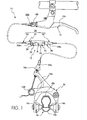
- a bicycle braking system 10 is illustrated with a bicycle cable structure 12 in accordance with a first embodiment.
- the bicycle cable structure 12 operatively interconnects a brake lever 14 to a bicycle brake caliper 16.
- the brake lever 14 operates the brake caliper 16 to stop or slow rotation of a bicycle wheel 18 by squeezing a rim 18a of the bicycle wheel 18 with a pair of brake pads 16a on the ends of a pair of brake arms 16b.
- the bicycle cable structure 12 is used in a bicycle braking system, the bicycle cable structure 12 can be used to operatively interconnect other cable operated bicycle components.
- the bicycle cable structure 12 includes an inner wire or cable 20, a first outer case 22 and a second outer case 24.
- the bicycle cable structure 12 further includes an adjustment structure 26 that is disposed between adjacent ends 22a and 24a of the first and second outer cases 22 and 24.
- the first outer case 22 is disposed over a first section of the inner cable 20, while the second outer case 24 is disposed over a second section of the inner cable 20.
- the inner cable 20 and the first and second outer cases 22 and 24 constitute a control cable 28 with the adjustment structure 26 effectively adjusting an overall effective length of the first and second outer cases 22 and 24 between non-adjacent or distal ends 22b and 24b of the first and second outer cases 22 and 24.
- the inner cable 20 is fixed at a first end to the lever portion 14a of the brake lever 14 in a conventional manner.
- the inner cable 20 extends through the barrel adjuster 16c, and is fixed at a second end to one of the brake arms 16b with a bolt 16d in a conventional manner.
- the adjustment structure 26 basically includes a main body 30 and an operating member 32.
- a slider 34 is slidably disposed inside of the main body 30 and is moved longitudinally within the main body 30 by the operating member 32 as discussed below.
- the main body 30 includes a barrel adjuster 36 that is adjustably coupled to the main body 30 to variably fix a contact point of the adjacent end 24a of the second outer case 24 relative to the main body 30.
- the operating member 32 is pivotally mounted to the main body 30 for movement between a first position ( Figures 3, 5 , 6 and 9 ) and a second position ( Figures 4 , 8 and 10 ).
- the operating member 32 is movably connected to the main body 30 by a non-slidable connection between the first and second positions as discussed below.
- the operating member 32 maintains the adjacent ends 22a and 24a of the first and second outer cases 22 and 24 farther away from each other while the operating member 32 is in the first position as compared to the second position of the operating member 32.
- the first position of the operating member 32 constitutes a closed position in which the control cable 28 maintains the brake arms 16a and 16b of the bicycle brake caliper 16 in a ready position for the brake pads 16a to engage the bicycle rim 18a upon actuation of the brake lever 14.
- the second position of the operating member 32 constitutes an opened position in which the control cable 28 maintains the brake arms 16b of the bicycle brake caliper 16 in a spread apart position such that the tire 18b can pass between the brake pads 16a for removal of the bicycle wheel 18.
- the adjustment structure 26 adjusts an overall effective length of the first and second outer cases 22 and 24 by moving the operating member 32 relative to the main body 30. With the operating member 32 is in the first (closed) position ( Figures 1 , 3 , 5 , 6 and 9 ), the overall effective length of the first and second outer cases 22 and 24 is larger than when the operating member 32 is in the second (opened) position ( Figures 2 , 4 , 8 and 10 ). While the adjustment structure 26 is illustrated as being used in connection with a bicycle braking system, the adjustment structure 26 can be used with other cable operated bicycle components as needed and/or desired.
- the main body 30 has a first end 40 with a first opening 40a, a second end 42 with a second opening 42a and a through hole 44 extending through the main body 30 between the first and second openings 40a and 42a in the first and second ends 40 and 42.
- the main body 30 is also provided with two openings 46 that cooperate the slider 34 and two recesses 48 that cooperate the operating member 32 as discussed below.
- the first opening 40a slidably receives the adjacent end 22a of the first outer case 22.
- the second opening 42a is threaded for threadedly receiving the barrel adjuster 36 so that the barrel adjuster 36 is adjustably coupled to the second end 42 of the main body 30 to variably fix a contact point of the adjacent end 24a of the second outer case 24 relative to the second end 42 of the main body 30.
- the barrel adjuster 36 can be eliminated if desired so that the adjacent end 24a of the second outer case 24 directly contacts and abuts against the second end 42 of the main body 30.
- the operating member 32 is pivotally mounted to the main body 30 by a pivot pin 50 that defines a pivot axis A.
- the operating member 32 is a lever that is pivotally mounted to the main body 30 about the pivot axis A to move between the first and second positions.
- the operating member 32 is not limited to a lever.
- the operating member 32 (e.g. a lever) has a user grasping portion 52 and a pair of cam surfaces 54.
- the user grasping portion 52 and the cam surfaces 54 are oppositely spaced from the pivot axis A so that the rider can grasp the user grasping portion 52 to pivot the cam surfaces 54 about the pivot axis A to move between the first and second positions.
- the user grasping portion 52 is located is a retracted orientation next to the main body 30 while the operating member 32 (e.g. the lever) is in the first position, and the user grasping portion 52 is spaced from the main body 30 while the operating member 32 (e.g. the lever) is in the second position.
- the operating member 32 extends along the main body 30 in the first position such that accidental operation of the operating member 32 (e.g. the lever) is substantially prevented.
- the operating member 32 protrudes outwardly from the main body 30 in the second position such that the rider can easily determine that the adjustment structure 26 is in the opened or second position.
- the ends of the cam surfaces 54 are each provided with an abutment receiving recess 56, while the user grasping portion 52 is provided with a pair of protrusions 58.
- the abutment receiving recesses 56 and the protrusions 58 aid in maintaining the operating member 32 in the first position.
- the abutment receiving recesses 56 are arranged to receive the slider 34 while the operating member 32 is in the first position in order to maintain the first position.
- the protrusions 58 mate with the mating recesses 48 of the main body 30 for holding the operating member 32 in the first position.
- the mating recesses 48 of the main body 30 and the protrusions 58 of the operating member 32 constitute a first maintain structure for holding the operating member 32 in the first position. Also when the operating member 32 is in the first position, the abutment receiving recesses 56 are engaged by the slider 34 for holding the operating member 32 in the first position.
- the slider 34 includes a base portion 60 and a pair of extended portions 62 projecting from opposite sides of the base portion 60.
- the extended portions 62 protrude out of the openings 46 of the main body 30 so that the base portion 60 slides inside of the main body 30.
- the adjacent end 22a of the first outer case 22 receives the base portion 60 of the slider 34 such that the adjacent end 22a of the first outer case 22 and the slider 34 are moved together by the operating member 32.
- the extended portions 62 act as guide rails for controlling the relative movement of the slider 34 with respect to the main body 30.
- the extended portions 62 also act as abutments for the operating member 32 to move the adjacent end 22a of the first outer case 22 with respect to the adjacent end 24a of the second outer case 24 as the operating member 32 moves between the first and second positions.
- the cam surfaces 54 of the operating member 32 contact the extended portions 62 of the slider 34 and move the adjacent end 22a of the first outer case 22 via the slider 34 away from the adjacent end 24a of the second outer case 24 as the operating member 32 pivots from the second position to the first position.
- the abutment receiving recesses 56 of the operating member 32 are engaged by the extended portions 62 of the slider 34 for holding the operating member 32 (e.g. the lever) in the first position.
- the abutment receiving recesses 56 of the main body 30 and the extended portions 62 of the slider 34 constitute a second maintain structure for holding the operating member 32 in the first position.
- the bicycle cable structure 112 can be used with the brake lever 14 and the brake caliper 16 of Figures 1 and 2 .
- the bicycle cable structure 112 includes an adjustment structure 126 that cooperates with the inner cable 20 and the first and second outer cases 22 and 24 to operate the brake caliper 16 using the brake lever 14.
- the adjustment structure 126 is disposed between the adjacent ends 22a and 24a of the first and second outer cases 22 and 24 and that receives the inner cable 20 therethrough.
- the parts of the second embodiment that are identical to the parts of the first embodiment will be given the same reference numerals as the parts of the first embodiment.
- the descriptions of the parks of the second embodiment that are identical to the parts of the first embodiment may be omitted for the sake of brevity.
- the adjustment structure 126 uses a modified operating member 132.
- the operating member 132 is pivotally mounted to the main body 30 by a pivot pin 150 that defines the pivot axis A.
- the operating member 132 e.g. a lever
- the end of the cam surface 154 is provided with an abutment receiving recess 156, while the user grasping portion 152 is provided with a protrusion 158.
- the abutment receiving recess 156 cooperates with one of the extended portions 62 of the slider 34
- the protrusion 158 cooperates with one of the mating recesses 148 of the main body 30.
- the bicycle cable structure 212 can be used with the brake lever 14 and the brake caliper 16 of Figures 1 and 2 .
- the bicycle cable structure 212 includes an adjustment structure 226 that cooperates with the inner cable 20 and the first and second outer cases 22 and 24 to operate the brake caliper 16 using the brake lever 14.
- the adjustment structure 226 is disposed between the adjacent ends 22a and 24a of the first and second outer cases 22 and 24 and that receives the inner cable 20 therethrough.
- the adjustment structure 226 includes a modified main body 230 and a modified operating member 232.
- the adjustment structure 226 includes a slider 234 and a barrel adjuster 236 that are identical to the slider 34 and the barrel adjuster 36, respectively, except that the operating member 232 and the slider 234 are interconnected by a connecting link 238.
- the main body 230 has a first end 240 with a first opening (not shown), a second end 242 with a second opening (not shown), and a through hole (not shown), extending through the main body 230 between the first and second ends 240 and 242.
- the main body 230 has two openings 246 that cooperate the slider 234 and a recess 248 that cooperate the operating member 232. In view of the apparent similarity between the main bodies 30 and 230, the main body 230 will not be discussed in further detail.
- the operating member 232 is a lever member that is pivotally mounted to the main body 230 by a pivot pin 250 that defines the pivot axis A.
- the operating member 232 also has a user grasping portion 252 for moving the operating member 232 between the first and second positions.
- the operating member 232 is operatively contacted to the slider 234 by the connecting link 238 which is pivotally coupled to the slider 234 by a pivot pin 254 and which is pivotally coupled to the operating member 232 by a pivot pin 256.
- the pivot pin 256 defines a pivot axis B, while the pivot pin 254 defines a pivot axis C.
- the user grasping portion 252 is located is a retracted orientation next to the main body 230 while the operating member 232 (e.g. the lever) is in the first (closed) position, and the user grasping portion 252 is spaced from the main body 230 while the operating member 232 (e.g. the lever) is in the second (opened) position.
- the connecting link 238 pushes the slider 234 and the adjacent end 22a of the first outer case 22 away from the adjacent end 24a of the second outer case 24 as the operating member 232 is pivoted from the second (opened) position to the first (closed) position. Since the operation of the adjustment structure 226 is readily apparent due to the similarities to the adjustment structure 26, a further discussion of the operation of the adjustment structure 226 will be omitted for the sake of brevity.
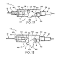
- the bicycle cable structure 312 is very similar to the bicycle cable structure 212.
- the bicycle cable structure 312 can be used with the brake lever 14 and the brake caliper 16 of Figures 1 and 2 .
- the bicycle cable structure 312 includes an adjustment structure 326 that cooperates with the inner cable 20 and the first and second outer cases 22 and 24 to operate the brake caliper 16 using the brake lever 14.
- the adjustment structure 326 is disposed between the adjacent ends 22a and 24a of the first and second outer cases 22 and 24 and that receives the inner cable 20 therethrough.
- the adjustment structure 326 includes a modified main body 330 and a modified operating member 332 that are more similar to the third embodiment.
- the adjustment structure 326 includes a slider 334 and a barrel adjuster 336 that are identical to the slider 34 and the barrel adjuster 36, respectively, except that the operating member 332 and the slider 334 are interconnected by a connecting link 338.
- the main body 330 has a first end 340 with a first opening (not shown), a second end 342 with a second opening (not shown), and a through hole (not shown), extending through the main body 330 between the first and second ends 340 and 342.
- the main body 330 has two openings 346 that cooperate the slider 334 and a recess 348 that cooperate the operating member 332. In view of the apparent similarity between the main bodies 30 and 330, the main body 330 will not be discussed in further detail.
- the operating member 332 is a lever member that is pivotally mounted to the main body 330 by a pivot pin 350 that defines the pivot axis A.
- the operating member 332 also has a user grasping portion 352 for moving the operating member 332 between the first and second positions.
- the operating member 332 is operatively contacted to the slider 334 by the connecting link 338 which is pivotally coupled to the slider 334 by a pivot pin 354 and which is pivotally coupled to the operating member 332 by a pivot pin 356.
- the pivot pin 356 defines the pivot axis B, while the pivot pin 354 defines the pivot axis C.
- the adjustment structure 326 differs from the adjustment structure 226 in that the pivot axes A, B and C are aligned when the operating member 332 is in the first (closed) position) in the adjustment structure 326, while the pivot axes A, B and C are not aligned in the adjustment structure 226.
- the user grasping portion 352 is located is a retracted orientation next to the main body 330 while the operating member 332 (e.g. the lever) is in the first (closed) position, and the user grasping portion 352 is spaced from the main body 330 while the operating member 332 (e.g. the lever) is in the second (opened) position.
- the connecting link 338 pushes the slider 334 and the adjacent end 22a of the first outer case 22 away from the adjacent end 24a of the second outer case 24 as the operating member 332 is pivoted from the second (opened) position to the first (closed) position. Since the operation of the adjustment structure 326 is readily apparent due to the similarities to the adjustment structures 26, 126 and 226, a further discussion of the operation of the adjustment structure 326 will be omitted for the sake of brevity.
- the bicycle cable structure 412 is very similar to the bicycle cable structures 212 and 312.
- the bicycle cable structure 412 can be used with the brake lever 14 and the brake caliper 16 of Figures 1 and 2 .
- the bicycle cable structure 412 includes an adjustment structure 426 that cooperates with the inner cable 20 and the first and second outer cases 22 and 24 to operate the brake caliper 16 using the brake lever 14.
- the adjustment structure 426 is disposed between the adjacent ends 22a and 24a of the first and second outer cases 22 and 24 and that receives the inner cable 20 therethrough.
- the adjustment structure 426 includes a modified main body 430 and a modified operating member 432 that are more similar to the third and fourth embodiments.
- the adjustment structure 426 includes a slider 434 and a barrel adjuster 436 that are identical to the slider 34 and the barrel adjuster 36, respectively, except that the operating member 432 and the slider 434 are interconnected by a connecting link 438.
- the main body 430 has a first end 440 with a first opening (not shown), a second end 442 with a second opening (not shown), and a through hole (not shown), extending through the main body 430 between the first and second ends 440 and 442.
- the main body 430 has two openings 446 that cooperate the slider 434. In view of the apparent similarity between the main bodies 30 and 430, the main body 430 will not be discussed in further detail.
- the operating member 432 is a lever member that is pivotally mounted to the main body 430 by a pivot pin 450 that defines the pivot axis A.
- the operating member 432 also has a user grasping portion 452 for moving the operating member 432 between the first and second positions.
- the operating member 432 is operatively contacted to the slider 434 by the connecting link 438 which is pivotally coupled to the slider 434 by a pivot pin 454 and which is pivotally coupled to the operating member 432 by a pivot pin 456.
- the pivot pin 456 defines the pivot axis B, while the pivot pin 454 defines the pivot axis C.
- the adjustment structure 426 differs from the adjustment structures 226 and 336 in that the pivot axis B passes across a centerline interconnecting the pivot axes A and C.
- the operating member 432 and the connecting link 438 form an over the center type of linkage arrangement.
- the user grasping portion 452 is located is a retracted orientation next to the main body 430 while the operating member 432 (e.g. the lever) is in the first (closed) position, and the user grasping portion 452 is spaced from the main body 430 while the operating member 432 (e.g. the lever) is in the second (opened) position.
- the connecting link 438 pushes the slider 434 and the adjacent end 22a of the first outer case 22 away from the adjacent end 24a of the second outer case 24 as the operating member 432 is pivoted from the second (opened) position to the first (closed) position. Since the operation of the adjustment structure 426 is readily apparent due to the similarities to the adjustment structures 26, 126 and 226, a further discussion of the operation of the adjustment structure 426 will be omitted for the sake of brevity.
- the bicycle cable structure 512 can be used with the brake lever 14 and the brake caliper 16 of Figures 1 and 2 .
- the bicycle cable structure 512 includes an adjustment structure 526 that cooperates with the inner cable 20 and the first and second outer cases 22 and 24 to operate the brake caliper 16 using the brake lever 14.
- the adjustment structure 526 is disposed between the adjacent ends 22a and 24a of the first and second outer cases 22 and 24 and that receives the inner cable 20 therethrough.
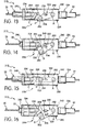
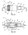
- the adjustment structure 526 includes a main body 530 and a twistable operating member 532.
- the main body 530 includes a barrel adjuster 536 that are identical to the barrel adjuster 36.
- the main body 530 further includes a first end 540 with a first opening 540a, a second end 542 with a second opening 542a, and a through hole 544 extending through the main body 530 between the first and second openings 540a and 542a.
- the main body 530 further includes a cam surface 546.
- the operating member 532 is a twistable member that is twistably mounted to the main body 530 to twist about the longitudinal axis of the inner cable 20.
- the operating member 532 has a user grasping portion 532a for twisting the operating member 532 between a first position shown in Figures 19 and 20 and a second position shown in Figures 21 and 22 .
- the operating member 532 includes a first end 550 with a first opening 550a, a second end 552 with a second opening 552a, and a through hole 554 extending through the operating member 532 between the first and second openings 550a and 552a.
- the operating member 532 further includes a cam surface 556 that cooperates with the cam surface 546 of the main body 530 to move the operating member 532 axially along the inner cable 20 in response to twisting of the operating member 532.
- twisting the operating member 532 causes the cam surface 556 to ride on the cam surface 546 of the main body 530 such that the first end 550 moves the adjacent end 22a of the first outer case 22 away from the adjacent end 24a of the second outer case 24 as the operating member 332 is twisted from the second (opened) position to the first (closed) position.
Landscapes
- Engineering & Computer Science (AREA)
- Mechanical Engineering (AREA)
- General Engineering & Computer Science (AREA)
- Transportation (AREA)
- Health & Medical Sciences (AREA)
- Oral & Maxillofacial Surgery (AREA)
- Steering Devices For Bicycles And Motorcycles (AREA)
- Mechanical Control Devices (AREA)
- Flexible Shafts (AREA)
- Braking Arrangements (AREA)
- Transmission Of Braking Force In Braking Systems (AREA)
Applications Claiming Priority (1)
| Application Number | Priority Date | Filing Date | Title |
|---|---|---|---|
| US13/273,429 US8746107B2 (en) | 2011-10-14 | 2011-10-14 | Bicycle cable structure |
Publications (3)
| Publication Number | Publication Date |
|---|---|
| EP2581279A2 true EP2581279A2 (de) | 2013-04-17 |
| EP2581279A3 EP2581279A3 (de) | 2014-06-11 |
| EP2581279B1 EP2581279B1 (de) | 2015-12-30 |
Family
ID=47172313
Family Applications (1)
| Application Number | Title | Priority Date | Filing Date |
|---|---|---|---|
| EP12187988.6A Active EP2581279B1 (de) | 2011-10-14 | 2012-10-10 | Kabelstruktur für ein Fahrrad |
Country Status (4)
| Country | Link |
|---|---|
| US (1) | US8746107B2 (de) |
| EP (1) | EP2581279B1 (de) |
| CN (1) | CN103043167B (de) |
| TW (1) | TWI529092B (de) |
Families Citing this family (3)
| Publication number | Priority date | Publication date | Assignee | Title |
|---|---|---|---|---|
| US9726216B2 (en) | 2013-02-04 | 2017-08-08 | Shimano Inc. | Cable adjusting unit |
| US9874238B2 (en) * | 2013-04-24 | 2018-01-23 | Shimano Inc. | Bicycle end cap |
| USD808306S1 (en) * | 2015-07-07 | 2018-01-23 | Yuan-Hung WEN | Bicycle cable |
Citations (2)
| Publication number | Priority date | Publication date | Assignee | Title |
|---|---|---|---|---|
| US7614634B2 (en) | 2007-04-13 | 2009-11-10 | Felt Racing, Llc | Aerodynamic time trial bike |
| US7946395B1 (en) | 2010-04-19 | 2011-05-24 | Tektro Technology Corporation | Front brake of racing bicycle |
Family Cites Families (32)
| Publication number | Priority date | Publication date | Assignee | Title |
|---|---|---|---|---|
| GB482404A (en) * | 1937-03-13 | 1938-03-29 | Exactor Control Company Ltd | Improvements in or relating to mechanical remote control apparatus |
| US2574281A (en) * | 1945-04-23 | 1951-11-06 | Olson John | Push or pull toggle clamp |
| JPS5145853B2 (de) * | 1973-07-31 | 1976-12-06 | ||
| JPS5164247A (en) * | 1974-11-28 | 1976-06-03 | Yoshigai Kikai Kinzoku Co Ltd | Bureekino jidochoseisochi |
| FR2482744A1 (fr) * | 1980-05-14 | 1981-11-20 | Dba | Dispositif de rattrapage automatique de jeu pour commande mecanique |
| US4456101A (en) * | 1980-11-08 | 1984-06-26 | Honda Giken Kogyo Kabushiki Kaisha | Vehicular brake operating system |
| US5109968A (en) * | 1991-03-04 | 1992-05-05 | Pollitt Gary M | Clutch oscillator assembly |
| US5540304A (en) * | 1993-06-24 | 1996-07-30 | Hawkins; Rollin D. | Single-handled vehicle brake system |
| DE9421068U1 (de) * | 1993-08-04 | 1995-03-23 | Kuester & Co Gmbh | Vorrichtung zur Längeneinstellung von mechanisch-flexiblen Fernbetätigungen o.dgl. |
| GB9321287D0 (en) * | 1993-10-15 | 1993-12-08 | Bowden Controls Ltd | Cable control |
| NL9301878A (nl) * | 1993-11-01 | 1995-06-01 | Koga B V | Inrichting voor het begrenzen van een kracht. |
| CN2194328Y (zh) * | 1994-05-12 | 1995-04-12 | 温俊德 | 可调整长度的刹车线 |
| DE4427772A1 (de) * | 1994-08-05 | 1996-02-08 | Andreas Unsicker | Fahrradschloß |
| US5653148A (en) * | 1995-12-15 | 1997-08-05 | Teleflex Incorporated | Conduit shortening adjustment assembly |
| US5685199A (en) * | 1996-05-02 | 1997-11-11 | Teleflex Incorporated | Push-pull control with opposing collet adjustment II |
| US5857386A (en) * | 1996-11-21 | 1999-01-12 | Teleflex Incorporated | Pivot-arm overtravel in a motion transmitting remote |
| ES2140298B1 (es) * | 1997-04-23 | 2001-03-01 | Fico Cables Sa | Dispositivo ajustador para cables de mando. |
| US5906140A (en) * | 1997-09-15 | 1999-05-25 | Sram Corporation | Slotted brake housing |
| DE60006173T2 (de) * | 1999-03-05 | 2004-05-19 | Shimano Inc., Sakai | Bremskraftmodulator für eine Fahrradbremse |
| CN1165446C (zh) * | 1999-03-05 | 2004-09-08 | 株式会社岛野 | 自行车刹车器用刹车特性变更装置 |
| US6212969B1 (en) * | 2000-02-14 | 2001-04-10 | Kuo Yung-Pin | Brake device for simultaneously actuating two brake mechanisms |
| JP3626681B2 (ja) * | 2000-12-27 | 2005-03-09 | 株式会社シマノ | 自転車用制動ケーブル係止具及び自転車用制動レバー |
| US7152498B2 (en) * | 2003-12-03 | 2006-12-26 | Shimano Inc. | Bicycle control cable fixing device |
| US7281611B2 (en) * | 2005-02-18 | 2007-10-16 | Szu-Fang Tsai | Bicycle handbrake conduit structure |
| US7303052B2 (en) * | 2005-04-27 | 2007-12-04 | Szu-Fang Tsai | Device for tightening and loosening bicycle brake wire |
| DE102005040861B4 (de) * | 2005-08-29 | 2011-03-24 | Fico Cables, Lda. | Einstellvorrichtung für einen Kabelzug und Kabelzug |
| US7540400B2 (en) * | 2006-01-06 | 2009-06-02 | Staples The Office Superstore, Llc | Stapler having a moveable strike plate with lockout mechanism |
| DE102006036283B4 (de) * | 2006-08-03 | 2008-06-19 | Fico Cables Lda | Einstellmechanismus zur Längeneinstellung eines Bowdenzugs |
| DE102007025205A1 (de) * | 2007-05-30 | 2008-12-04 | Sram Deutschland Gmbh | Einstellvorrichtung |
| FR2921450B1 (fr) * | 2007-09-26 | 2009-12-04 | Faurecia Sieges Automobile | Dispositif d'ajustement de la longueur d'un cable de commande, et cable de commande comportant un tel dispositif. |
| US8235997B2 (en) * | 2008-01-29 | 2012-08-07 | Pioneer Surgical Technology, Inc. | Rod locking instrument |
| US20090301252A1 (en) * | 2008-06-06 | 2009-12-10 | Chia-Wei Hsu | Bicycle brake lever |
-
2011
- 2011-10-14 US US13/273,429 patent/US8746107B2/en active Active
-
2012
- 2012-05-25 TW TW101118769A patent/TWI529092B/zh active
- 2012-07-11 CN CN201210238634.1A patent/CN103043167B/zh active Active
- 2012-10-10 EP EP12187988.6A patent/EP2581279B1/de active Active
Patent Citations (2)
| Publication number | Priority date | Publication date | Assignee | Title |
|---|---|---|---|---|
| US7614634B2 (en) | 2007-04-13 | 2009-11-10 | Felt Racing, Llc | Aerodynamic time trial bike |
| US7946395B1 (en) | 2010-04-19 | 2011-05-24 | Tektro Technology Corporation | Front brake of racing bicycle |
Also Published As
| Publication number | Publication date |
|---|---|
| CN103043167B (zh) | 2015-01-28 |
| EP2581279A3 (de) | 2014-06-11 |
| TW201315645A (zh) | 2013-04-16 |
| TWI529092B (zh) | 2016-04-11 |
| CN103043167A (zh) | 2013-04-17 |
| EP2581279B1 (de) | 2015-12-30 |
| US20130091975A1 (en) | 2013-04-18 |
| US8746107B2 (en) | 2014-06-10 |
Similar Documents
| Publication | Publication Date | Title |
|---|---|---|
| US9926039B2 (en) | Front derailleur | |
| EP2072390B1 (de) | Betätigungsvorrichtung für ein Fahrrad | |
| EP2574535B1 (de) | Steuerungseinrichtung für ein Fahrrad | |
| EP2927107B1 (de) | Felgenbremse | |
| EP0916570A2 (de) | Einstellvorrichtung für Bowdenzug | |
| EP1728714A2 (de) | Fahrradsteuerungsvorrichtung | |
| EP2065298B1 (de) | Steuerungseinrichtung für ein Fahrrad | |
| EP2535250B1 (de) | Fahrradteilbetätigungsvorrichtung | |
| CN102101516A (zh) | 自行车液压制动致动装置 | |
| EP2581279B1 (de) | Kabelstruktur für ein Fahrrad | |
| CN109665060B (zh) | 自行车控制设备 | |
| EP1609715B1 (de) | Vorderer Umwerfer für ein Fahrrad | |
| US9290234B2 (en) | Bicycle pedal | |
| US8881619B2 (en) | Bicycle control device | |
| CN106314661B (zh) | 自行车刹车和构造所述刹车的杆的表面部的轮廓的方法 | |
| US10689060B2 (en) | Bicycle operating device | |
| US10005513B2 (en) | Bicycle operating device | |
| TWI699305B (zh) | 自行車操作裝置 | |
| CN107235106B (zh) | 自行车操作装置 | |
| EP2110305A1 (de) | Fahrradkettenschaltung |
Legal Events
| Date | Code | Title | Description |
|---|---|---|---|
| PUAI | Public reference made under article 153(3) epc to a published international application that has entered the european phase |
Free format text: ORIGINAL CODE: 0009012 |
|
| AK | Designated contracting states |
Kind code of ref document: A2 Designated state(s): AL AT BE BG CH CY CZ DE DK EE ES FI FR GB GR HR HU IE IS IT LI LT LU LV MC MK MT NL NO PL PT RO RS SE SI SK SM TR |
|
| AX | Request for extension of the european patent |
Extension state: BA ME |
|
| PUAL | Search report despatched |
Free format text: ORIGINAL CODE: 0009013 |
|
| AK | Designated contracting states |
Kind code of ref document: A3 Designated state(s): AL AT BE BG CH CY CZ DE DK EE ES FI FR GB GR HR HU IE IS IT LI LT LU LV MC MK MT NL NO PL PT RO RS SE SI SK SM TR |
|
| AX | Request for extension of the european patent |
Extension state: BA ME |
|
| RIC1 | Information provided on ipc code assigned before grant |
Ipc: F16C 1/22 20060101ALI20140506BHEP Ipc: B60T 11/04 20060101AFI20140506BHEP Ipc: B62L 3/02 20060101ALI20140506BHEP |
|
| 17P | Request for examination filed |
Effective date: 20141124 |
|
| RBV | Designated contracting states (corrected) |
Designated state(s): AL AT BE BG CH CY CZ DE DK EE ES FI FR GB GR HR HU IE IS IT LI LT LU LV MC MK MT NL NO PL PT RO RS SE SI SK SM TR |
|
| GRAP | Despatch of communication of intention to grant a patent |
Free format text: ORIGINAL CODE: EPIDOSNIGR1 |
|
| INTG | Intention to grant announced |
Effective date: 20150608 |
|
| GRAS | Grant fee paid |
Free format text: ORIGINAL CODE: EPIDOSNIGR3 |
|
| GRAA | (expected) grant |
Free format text: ORIGINAL CODE: 0009210 |
|
| AK | Designated contracting states |
Kind code of ref document: B1 Designated state(s): AL AT BE BG CH CY CZ DE DK EE ES FI FR GB GR HR HU IE IS IT LI LT LU LV MC MK MT NL NO PL PT RO RS SE SI SK SM TR |
|
| REG | Reference to a national code |
Ref country code: GB Ref legal event code: FG4D |
|
| REG | Reference to a national code |
Ref country code: CH Ref legal event code: EP |
|
| REG | Reference to a national code |
Ref country code: AT Ref legal event code: REF Ref document number: 767308 Country of ref document: AT Kind code of ref document: T Effective date: 20160115 |
|
| REG | Reference to a national code |
Ref country code: IE Ref legal event code: FG4D |
|
| REG | Reference to a national code |
Ref country code: DE Ref legal event code: R096 Ref document number: 602012013327 Country of ref document: DE |
|
| REG | Reference to a national code |
Ref country code: LT Ref legal event code: MG4D |
|
| PG25 | Lapsed in a contracting state [announced via postgrant information from national office to epo] |
Ref country code: NO Free format text: LAPSE BECAUSE OF FAILURE TO SUBMIT A TRANSLATION OF THE DESCRIPTION OR TO PAY THE FEE WITHIN THE PRESCRIBED TIME-LIMIT Effective date: 20160330 Ref country code: LT Free format text: LAPSE BECAUSE OF FAILURE TO SUBMIT A TRANSLATION OF THE DESCRIPTION OR TO PAY THE FEE WITHIN THE PRESCRIBED TIME-LIMIT Effective date: 20151230 Ref country code: HR Free format text: LAPSE BECAUSE OF FAILURE TO SUBMIT A TRANSLATION OF THE DESCRIPTION OR TO PAY THE FEE WITHIN THE PRESCRIBED TIME-LIMIT Effective date: 20151230 |
|
| REG | Reference to a national code |
Ref country code: NL Ref legal event code: MP Effective date: 20151230 |
|
| REG | Reference to a national code |
Ref country code: AT Ref legal event code: MK05 Ref document number: 767308 Country of ref document: AT Kind code of ref document: T Effective date: 20151230 |
|
| PG25 | Lapsed in a contracting state [announced via postgrant information from national office to epo] |
Ref country code: FI Free format text: LAPSE BECAUSE OF FAILURE TO SUBMIT A TRANSLATION OF THE DESCRIPTION OR TO PAY THE FEE WITHIN THE PRESCRIBED TIME-LIMIT Effective date: 20151230 Ref country code: RS Free format text: LAPSE BECAUSE OF FAILURE TO SUBMIT A TRANSLATION OF THE DESCRIPTION OR TO PAY THE FEE WITHIN THE PRESCRIBED TIME-LIMIT Effective date: 20151230 Ref country code: GR Free format text: LAPSE BECAUSE OF FAILURE TO SUBMIT A TRANSLATION OF THE DESCRIPTION OR TO PAY THE FEE WITHIN THE PRESCRIBED TIME-LIMIT Effective date: 20160331 Ref country code: SE Free format text: LAPSE BECAUSE OF FAILURE TO SUBMIT A TRANSLATION OF THE DESCRIPTION OR TO PAY THE FEE WITHIN THE PRESCRIBED TIME-LIMIT Effective date: 20151230 Ref country code: LV Free format text: LAPSE BECAUSE OF FAILURE TO SUBMIT A TRANSLATION OF THE DESCRIPTION OR TO PAY THE FEE WITHIN THE PRESCRIBED TIME-LIMIT Effective date: 20151230 |
|
| PG25 | Lapsed in a contracting state [announced via postgrant information from national office to epo] |
Ref country code: NL Free format text: LAPSE BECAUSE OF FAILURE TO SUBMIT A TRANSLATION OF THE DESCRIPTION OR TO PAY THE FEE WITHIN THE PRESCRIBED TIME-LIMIT Effective date: 20151230 |
|
| PG25 | Lapsed in a contracting state [announced via postgrant information from national office to epo] |
Ref country code: ES Free format text: LAPSE BECAUSE OF FAILURE TO SUBMIT A TRANSLATION OF THE DESCRIPTION OR TO PAY THE FEE WITHIN THE PRESCRIBED TIME-LIMIT Effective date: 20151230 Ref country code: CZ Free format text: LAPSE BECAUSE OF FAILURE TO SUBMIT A TRANSLATION OF THE DESCRIPTION OR TO PAY THE FEE WITHIN THE PRESCRIBED TIME-LIMIT Effective date: 20151230 |
|
| PG25 | Lapsed in a contracting state [announced via postgrant information from national office to epo] |
Ref country code: SM Free format text: LAPSE BECAUSE OF FAILURE TO SUBMIT A TRANSLATION OF THE DESCRIPTION OR TO PAY THE FEE WITHIN THE PRESCRIBED TIME-LIMIT Effective date: 20151230 Ref country code: PT Free format text: LAPSE BECAUSE OF FAILURE TO SUBMIT A TRANSLATION OF THE DESCRIPTION OR TO PAY THE FEE WITHIN THE PRESCRIBED TIME-LIMIT Effective date: 20160502 Ref country code: RO Free format text: LAPSE BECAUSE OF FAILURE TO SUBMIT A TRANSLATION OF THE DESCRIPTION OR TO PAY THE FEE WITHIN THE PRESCRIBED TIME-LIMIT Effective date: 20151230 Ref country code: SK Free format text: LAPSE BECAUSE OF FAILURE TO SUBMIT A TRANSLATION OF THE DESCRIPTION OR TO PAY THE FEE WITHIN THE PRESCRIBED TIME-LIMIT Effective date: 20151230 Ref country code: AT Free format text: LAPSE BECAUSE OF FAILURE TO SUBMIT A TRANSLATION OF THE DESCRIPTION OR TO PAY THE FEE WITHIN THE PRESCRIBED TIME-LIMIT Effective date: 20151230 Ref country code: EE Free format text: LAPSE BECAUSE OF FAILURE TO SUBMIT A TRANSLATION OF THE DESCRIPTION OR TO PAY THE FEE WITHIN THE PRESCRIBED TIME-LIMIT Effective date: 20151230 Ref country code: PL Free format text: LAPSE BECAUSE OF FAILURE TO SUBMIT A TRANSLATION OF THE DESCRIPTION OR TO PAY THE FEE WITHIN THE PRESCRIBED TIME-LIMIT Effective date: 20151230 Ref country code: IS Free format text: LAPSE BECAUSE OF FAILURE TO SUBMIT A TRANSLATION OF THE DESCRIPTION OR TO PAY THE FEE WITHIN THE PRESCRIBED TIME-LIMIT Effective date: 20160430 |
|
| REG | Reference to a national code |
Ref country code: DE Ref legal event code: R097 Ref document number: 602012013327 Country of ref document: DE |
|
| PG25 | Lapsed in a contracting state [announced via postgrant information from national office to epo] |
Ref country code: DK Free format text: LAPSE BECAUSE OF FAILURE TO SUBMIT A TRANSLATION OF THE DESCRIPTION OR TO PAY THE FEE WITHIN THE PRESCRIBED TIME-LIMIT Effective date: 20151230 |
|
| PLBE | No opposition filed within time limit |
Free format text: ORIGINAL CODE: 0009261 |
|
| STAA | Information on the status of an ep patent application or granted ep patent |
Free format text: STATUS: NO OPPOSITION FILED WITHIN TIME LIMIT |
|
| 26N | No opposition filed |
Effective date: 20161003 |
|
| PG25 | Lapsed in a contracting state [announced via postgrant information from national office to epo] |
Ref country code: BE Free format text: LAPSE BECAUSE OF FAILURE TO SUBMIT A TRANSLATION OF THE DESCRIPTION OR TO PAY THE FEE WITHIN THE PRESCRIBED TIME-LIMIT Effective date: 20151230 |
|
| PG25 | Lapsed in a contracting state [announced via postgrant information from national office to epo] |
Ref country code: SI Free format text: LAPSE BECAUSE OF FAILURE TO SUBMIT A TRANSLATION OF THE DESCRIPTION OR TO PAY THE FEE WITHIN THE PRESCRIBED TIME-LIMIT Effective date: 20151230 |
|
| REG | Reference to a national code |
Ref country code: CH Ref legal event code: PL |
|
| GBPC | Gb: european patent ceased through non-payment of renewal fee |
Effective date: 20161010 |
|
| REG | Reference to a national code |
Ref country code: IE Ref legal event code: MM4A |
|
| REG | Reference to a national code |
Ref country code: FR Ref legal event code: ST Effective date: 20170630 |
|
| PG25 | Lapsed in a contracting state [announced via postgrant information from national office to epo] |
Ref country code: LI Free format text: LAPSE BECAUSE OF NON-PAYMENT OF DUE FEES Effective date: 20161031 Ref country code: CH Free format text: LAPSE BECAUSE OF NON-PAYMENT OF DUE FEES Effective date: 20161031 Ref country code: GB Free format text: LAPSE BECAUSE OF NON-PAYMENT OF DUE FEES Effective date: 20161010 Ref country code: FR Free format text: LAPSE BECAUSE OF NON-PAYMENT OF DUE FEES Effective date: 20161102 |
|
| PG25 | Lapsed in a contracting state [announced via postgrant information from national office to epo] |
Ref country code: LU Free format text: LAPSE BECAUSE OF NON-PAYMENT OF DUE FEES Effective date: 20161010 |
|
| PG25 | Lapsed in a contracting state [announced via postgrant information from national office to epo] |
Ref country code: IE Free format text: LAPSE BECAUSE OF NON-PAYMENT OF DUE FEES Effective date: 20161010 |
|
| PGFP | Annual fee paid to national office [announced via postgrant information from national office to epo] |
Ref country code: IT Payment date: 20171023 Year of fee payment: 6 |
|
| PG25 | Lapsed in a contracting state [announced via postgrant information from national office to epo] |
Ref country code: HU Free format text: LAPSE BECAUSE OF FAILURE TO SUBMIT A TRANSLATION OF THE DESCRIPTION OR TO PAY THE FEE WITHIN THE PRESCRIBED TIME-LIMIT; INVALID AB INITIO Effective date: 20121010 Ref country code: CY Free format text: LAPSE BECAUSE OF FAILURE TO SUBMIT A TRANSLATION OF THE DESCRIPTION OR TO PAY THE FEE WITHIN THE PRESCRIBED TIME-LIMIT Effective date: 20151230 |
|
| PG25 | Lapsed in a contracting state [announced via postgrant information from national office to epo] |
Ref country code: TR Free format text: LAPSE BECAUSE OF FAILURE TO SUBMIT A TRANSLATION OF THE DESCRIPTION OR TO PAY THE FEE WITHIN THE PRESCRIBED TIME-LIMIT Effective date: 20151230 Ref country code: MK Free format text: LAPSE BECAUSE OF FAILURE TO SUBMIT A TRANSLATION OF THE DESCRIPTION OR TO PAY THE FEE WITHIN THE PRESCRIBED TIME-LIMIT Effective date: 20151230 Ref country code: MT Free format text: LAPSE BECAUSE OF NON-PAYMENT OF DUE FEES Effective date: 20161031 Ref country code: MC Free format text: LAPSE BECAUSE OF FAILURE TO SUBMIT A TRANSLATION OF THE DESCRIPTION OR TO PAY THE FEE WITHIN THE PRESCRIBED TIME-LIMIT Effective date: 20151230 |
|
| PG25 | Lapsed in a contracting state [announced via postgrant information from national office to epo] |
Ref country code: BG Free format text: LAPSE BECAUSE OF FAILURE TO SUBMIT A TRANSLATION OF THE DESCRIPTION OR TO PAY THE FEE WITHIN THE PRESCRIBED TIME-LIMIT Effective date: 20151230 |
|
| PG25 | Lapsed in a contracting state [announced via postgrant information from national office to epo] |
Ref country code: AL Free format text: LAPSE BECAUSE OF FAILURE TO SUBMIT A TRANSLATION OF THE DESCRIPTION OR TO PAY THE FEE WITHIN THE PRESCRIBED TIME-LIMIT Effective date: 20151230 |
|
| PG25 | Lapsed in a contracting state [announced via postgrant information from national office to epo] |
Ref country code: IT Free format text: LAPSE BECAUSE OF NON-PAYMENT OF DUE FEES Effective date: 20181010 |
|
| P01 | Opt-out of the competence of the unified patent court (upc) registered |
Effective date: 20230428 |
|
| PGFP | Annual fee paid to national office [announced via postgrant information from national office to epo] |
Ref country code: DE Payment date: 20251021 Year of fee payment: 14 |