EP2579551A1 - Verfahren und Vorrichtung zur automatischen Durchführung einer Anwendungsfunktion einer elektronischen Vorrichtung basierend auf der Erkennung einer Änderung in der physischen Konfiguration der Vorrichtung - Google Patents
Verfahren und Vorrichtung zur automatischen Durchführung einer Anwendungsfunktion einer elektronischen Vorrichtung basierend auf der Erkennung einer Änderung in der physischen Konfiguration der Vorrichtung Download PDFInfo
- Publication number
- EP2579551A1 EP2579551A1 EP20110184846 EP11184846A EP2579551A1 EP 2579551 A1 EP2579551 A1 EP 2579551A1 EP 20110184846 EP20110184846 EP 20110184846 EP 11184846 A EP11184846 A EP 11184846A EP 2579551 A1 EP2579551 A1 EP 2579551A1
- Authority
- EP
- European Patent Office
- Prior art keywords
- electronic device
- component
- detecting
- application
- application function
- Prior art date
- Legal status (The legal status is an assumption and is not a legal conclusion. Google has not performed a legal analysis and makes no representation as to the accuracy of the status listed.)
- Granted
Links
- 230000008859 change Effects 0.000 title claims abstract description 32
- 238000000034 method Methods 0.000 title claims description 68
- 230000006870 function Effects 0.000 claims abstract description 51
- 230000004044 response Effects 0.000 claims abstract description 21
- 230000000977 initiatory effect Effects 0.000 claims description 4
- 230000001502 supplementing effect Effects 0.000 claims description 4
- 238000001514 detection method Methods 0.000 abstract description 19
- 238000013459 approach Methods 0.000 abstract description 13
- 230000000694 effects Effects 0.000 abstract description 11
- 238000004891 communication Methods 0.000 description 29
- 230000008878 coupling Effects 0.000 description 24
- 238000010168 coupling process Methods 0.000 description 24
- 238000005859 coupling reaction Methods 0.000 description 24
- 230000010399 physical interaction Effects 0.000 description 17
- 230000008569 process Effects 0.000 description 16
- 230000000875 corresponding effect Effects 0.000 description 13
- 238000010586 diagram Methods 0.000 description 13
- 230000009471 action Effects 0.000 description 9
- 230000003287 optical effect Effects 0.000 description 9
- 230000007246 mechanism Effects 0.000 description 7
- 238000012544 monitoring process Methods 0.000 description 7
- 230000008901 benefit Effects 0.000 description 4
- 230000001413 cellular effect Effects 0.000 description 4
- 230000004075 alteration Effects 0.000 description 3
- 238000005452 bending Methods 0.000 description 3
- 230000003993 interaction Effects 0.000 description 3
- 230000000670 limiting effect Effects 0.000 description 3
- 238000013507 mapping Methods 0.000 description 3
- 230000005355 Hall effect Effects 0.000 description 2
- 230000004888 barrier function Effects 0.000 description 2
- 230000001276 controlling effect Effects 0.000 description 2
- 238000005516 engineering process Methods 0.000 description 2
- 239000000835 fiber Substances 0.000 description 2
- 230000014509 gene expression Effects 0.000 description 2
- 238000012986 modification Methods 0.000 description 2
- 230000004048 modification Effects 0.000 description 2
- 238000000926 separation method Methods 0.000 description 2
- 239000000758 substrate Substances 0.000 description 2
- 238000010897 surface acoustic wave method Methods 0.000 description 2
- 230000001133 acceleration Effects 0.000 description 1
- 230000004913 activation Effects 0.000 description 1
- 230000006399 behavior Effects 0.000 description 1
- 230000015572 biosynthetic process Effects 0.000 description 1
- 230000004397 blinking Effects 0.000 description 1
- 238000006243 chemical reaction Methods 0.000 description 1
- 239000004020 conductor Substances 0.000 description 1
- 238000012790 confirmation Methods 0.000 description 1
- 238000012937 correction Methods 0.000 description 1
- 230000002596 correlated effect Effects 0.000 description 1
- 238000013479 data entry Methods 0.000 description 1
- 238000013461 design Methods 0.000 description 1
- 229910003460 diamond Inorganic materials 0.000 description 1
- 239000010432 diamond Substances 0.000 description 1
- 229920001746 electroactive polymer Polymers 0.000 description 1
- 210000003811 finger Anatomy 0.000 description 1
- 230000005484 gravity Effects 0.000 description 1
- 238000005286 illumination Methods 0.000 description 1
- AMGQUBHHOARCQH-UHFFFAOYSA-N indium;oxotin Chemical compound [In].[Sn]=O AMGQUBHHOARCQH-UHFFFAOYSA-N 0.000 description 1
- 239000000463 material Substances 0.000 description 1
- 238000012634 optical imaging Methods 0.000 description 1
- 230000002085 persistent effect Effects 0.000 description 1
- 238000012545 processing Methods 0.000 description 1
- 230000005855 radiation Effects 0.000 description 1
- 230000002441 reversible effect Effects 0.000 description 1
- 238000012552 review Methods 0.000 description 1
- 238000010079 rubber tapping Methods 0.000 description 1
- 230000005236 sound signal Effects 0.000 description 1
- 239000013589 supplement Substances 0.000 description 1
- 230000000153 supplemental effect Effects 0.000 description 1
- 230000001360 synchronised effect Effects 0.000 description 1
- 235000019640 taste Nutrition 0.000 description 1
- 230000002123 temporal effect Effects 0.000 description 1
- 210000003813 thumb Anatomy 0.000 description 1
- 230000007704 transition Effects 0.000 description 1
Images


Classifications
-
- H—ELECTRICITY
- H04—ELECTRIC COMMUNICATION TECHNIQUE
- H04M—TELEPHONIC COMMUNICATION
- H04M1/00—Substation equipment, e.g. for use by subscribers
- H04M1/02—Constructional features of telephone sets
- H04M1/0202—Portable telephone sets, e.g. cordless phones, mobile phones or bar type handsets
- H04M1/0206—Portable telephones comprising a plurality of mechanically joined movable body parts, e.g. hinged housings
- H04M1/0241—Portable telephones comprising a plurality of mechanically joined movable body parts, e.g. hinged housings using relative motion of the body parts to change the operational status of the telephone set, e.g. switching on/off, answering incoming call
- H04M1/0245—Portable telephones comprising a plurality of mechanically joined movable body parts, e.g. hinged housings using relative motion of the body parts to change the operational status of the telephone set, e.g. switching on/off, answering incoming call using open/close detection
-
- G—PHYSICS
- G06—COMPUTING; CALCULATING OR COUNTING
- G06F—ELECTRIC DIGITAL DATA PROCESSING
- G06F1/00—Details not covered by groups G06F3/00 - G06F13/00 and G06F21/00
- G06F1/16—Constructional details or arrangements
- G06F1/1613—Constructional details or arrangements for portable computers
- G06F1/1615—Constructional details or arrangements for portable computers with several enclosures having relative motions, each enclosure supporting at least one I/O or computing function
-
- G—PHYSICS
- G06—COMPUTING; CALCULATING OR COUNTING
- G06F—ELECTRIC DIGITAL DATA PROCESSING
- G06F1/00—Details not covered by groups G06F3/00 - G06F13/00 and G06F21/00
- G06F1/16—Constructional details or arrangements
- G06F1/1613—Constructional details or arrangements for portable computers
- G06F1/1626—Constructional details or arrangements for portable computers with a single-body enclosure integrating a flat display, e.g. Personal Digital Assistants [PDAs]
-
- G—PHYSICS
- G06—COMPUTING; CALCULATING OR COUNTING
- G06F—ELECTRIC DIGITAL DATA PROCESSING
- G06F1/00—Details not covered by groups G06F3/00 - G06F13/00 and G06F21/00
- G06F1/16—Constructional details or arrangements
- G06F1/1613—Constructional details or arrangements for portable computers
- G06F1/1633—Constructional details or arrangements of portable computers not specific to the type of enclosures covered by groups G06F1/1615 - G06F1/1626
- G06F1/1637—Details related to the display arrangement, including those related to the mounting of the display in the housing
- G06F1/1647—Details related to the display arrangement, including those related to the mounting of the display in the housing including at least an additional display
-
- G—PHYSICS
- G06—COMPUTING; CALCULATING OR COUNTING
- G06F—ELECTRIC DIGITAL DATA PROCESSING
- G06F1/00—Details not covered by groups G06F3/00 - G06F13/00 and G06F21/00
- G06F1/16—Constructional details or arrangements
- G06F1/1613—Constructional details or arrangements for portable computers
- G06F1/1633—Constructional details or arrangements of portable computers not specific to the type of enclosures covered by groups G06F1/1615 - G06F1/1626
- G06F1/1662—Details related to the integrated keyboard
- G06F1/1666—Arrangements for reducing the size of the integrated keyboard for transport, e.g. foldable keyboards, keyboards with collapsible keys
-
- G—PHYSICS
- G06—COMPUTING; CALCULATING OR COUNTING
- G06F—ELECTRIC DIGITAL DATA PROCESSING
- G06F1/00—Details not covered by groups G06F3/00 - G06F13/00 and G06F21/00
- G06F1/16—Constructional details or arrangements
- G06F1/1613—Constructional details or arrangements for portable computers
- G06F1/1633—Constructional details or arrangements of portable computers not specific to the type of enclosures covered by groups G06F1/1615 - G06F1/1626
- G06F1/1675—Miscellaneous details related to the relative movement between the different enclosures or enclosure parts
- G06F1/1677—Miscellaneous details related to the relative movement between the different enclosures or enclosure parts for detecting open or closed state or particular intermediate positions assumed by movable parts of the enclosure, e.g. detection of display lid position with respect to main body in a laptop, detection of opening of the cover of battery compartment
-
- G—PHYSICS
- G06—COMPUTING; CALCULATING OR COUNTING
- G06F—ELECTRIC DIGITAL DATA PROCESSING
- G06F3/00—Input arrangements for transferring data to be processed into a form capable of being handled by the computer; Output arrangements for transferring data from processing unit to output unit, e.g. interface arrangements
- G06F3/01—Input arrangements or combined input and output arrangements for interaction between user and computer
- G06F3/048—Interaction techniques based on graphical user interfaces [GUI]
- G06F3/0487—Interaction techniques based on graphical user interfaces [GUI] using specific features provided by the input device, e.g. functions controlled by the rotation of a mouse with dual sensing arrangements, or of the nature of the input device, e.g. tap gestures based on pressure sensed by a digitiser
- G06F3/0488—Interaction techniques based on graphical user interfaces [GUI] using specific features provided by the input device, e.g. functions controlled by the rotation of a mouse with dual sensing arrangements, or of the nature of the input device, e.g. tap gestures based on pressure sensed by a digitiser using a touch-screen or digitiser, e.g. input of commands through traced gestures
- G06F3/04886—Interaction techniques based on graphical user interfaces [GUI] using specific features provided by the input device, e.g. functions controlled by the rotation of a mouse with dual sensing arrangements, or of the nature of the input device, e.g. tap gestures based on pressure sensed by a digitiser using a touch-screen or digitiser, e.g. input of commands through traced gestures by partitioning the display area of the touch-screen or the surface of the digitising tablet into independently controllable areas, e.g. virtual keyboards or menus
-
- H—ELECTRICITY
- H04—ELECTRIC COMMUNICATION TECHNIQUE
- H04M—TELEPHONIC COMMUNICATION
- H04M1/00—Substation equipment, e.g. for use by subscribers
- H04M1/02—Constructional features of telephone sets
- H04M1/0202—Portable telephone sets, e.g. cordless phones, mobile phones or bar type handsets
- H04M1/0206—Portable telephones comprising a plurality of mechanically joined movable body parts, e.g. hinged housings
- H04M1/0208—Portable telephones comprising a plurality of mechanically joined movable body parts, e.g. hinged housings characterized by the relative motions of the body parts
-
- H—ELECTRICITY
- H04—ELECTRIC COMMUNICATION TECHNIQUE
- H04M—TELEPHONIC COMMUNICATION
- H04M1/00—Substation equipment, e.g. for use by subscribers
- H04M1/02—Constructional features of telephone sets
- H04M1/0202—Portable telephone sets, e.g. cordless phones, mobile phones or bar type handsets
- H04M1/0206—Portable telephones comprising a plurality of mechanically joined movable body parts, e.g. hinged housings
- H04M1/0247—Portable telephones comprising a plurality of mechanically joined movable body parts, e.g. hinged housings comprising more than two body parts
-
- H—ELECTRICITY
- H04—ELECTRIC COMMUNICATION TECHNIQUE
- H04M—TELEPHONIC COMMUNICATION
- H04M1/00—Substation equipment, e.g. for use by subscribers
- H04M1/02—Constructional features of telephone sets
- H04M1/23—Construction or mounting of dials or of equivalent devices; Means for facilitating the use thereof
Definitions
- This disclosed concept relates generally to electronic devices, including but not limited to, electronic devices that operate in conjunction with one or more components that may be physically movable.
- Electronic devices of various kinds are known in the art. Many such devices are relatively small and are intended to be readily carried on the person. Examples of electronic devices include, but are certainly not limited to, gaming devices, media players, portable communication devices including smartphones, personal digital assistants, electronic pads, tablets, laptop computers, electronic messaging devices, and so forth.
- the disclosure generally relates to an electronic device, which may be a portable electronic device in the examples described herein.
- electronic devices include mobile, or handheld, wireless communication devices such as pagers, cellular phones, cellular smart-phones, wireless organizers, personal digital assistants, wirelessly-enabled notebook computers, tablet computers, mobile Internet devices, and so forth.
- the electronic device may also be a portable electronic device without wireless communication capabilities, such as handheld electronic games, digital photograph albums, digital cameras, media players, e-book readers, and so forth. The foregoing can be further based, at least in part, on a detected orientation of the electronic device.
- these various embodiments provide for detecting a change in the physical configuration of an electronic device having at least two physical configurations and automatically performing an application function of the electronic device in response to such detection.
- this can comprise detecting a change in configuration as regards a native component of the electronic device (such as, for example, whether the component is configured in a deployed position or a non-deployed position).
- this activity can comprise moving at least a portion of the application's user interface to the aforementioned component.
- this activity can comprise accessing preferences information (by, for example, accessing stored information that maps particular application functions to corresponding physical configurations of the electronic device).
- the foregoing approach will also accommodate detecting a subsequent change in the physical configuration of the electronic device and responsively automatically initiating another particular application function of the electronic device or automatically supplementing current application functionality of the electronic device with additional application functionality.
- These approaches are also readily scalable and will accommodate any number and type of device, component, and/or function.
- this component 101 comprises a discrete component that is physically distinct onto itself (although, in at least some application settings and at least some of the time this discrete component 101 may be physically coupled to the electronic device 100).
- the electronic device 100 and the component 101 may be similar.
- both the electronic device 100 and the component 101 may be peer devices, such as cellular smart-phones.
- this component 101 comprises a native component of the electronic device 100 and is considered an original and integral part of that electronic device 100.
- FIG. 1-1 presents this component 101 as being smaller than the electronic device 100.
- the component 101 can be the same size as the electronic device 100.
- the component 101 can be larger than the electronic device 100.
- these various components can similarly share a same size or can vary in size.
- this component 101 can physically move relative to the electronic device 100.
- Reference to movement refers to movement that is accommodated as an ordinary capability per the design of these elements. Accordingly, movement that can only be achieved by, for example, damaging or breaking one or both of these elements is not included within the motion contemplated herein.
- movement types can include, for example, various modes of articulation including, but not limited to, pivoting, rotating, folding/unfolding/bending (as generally represented by the arrows denoted by reference numerals 102 in FIG. 1-1 and 103 in FIG. 1-2 ), sliding (as generally represented by the arrows denoted by reference numerals 104 in FIG. 1-3 , 105 and 106 in FIG. 1-4 ), telescoping/elongating, realigning (as generally represented by any of the foregoing arrows as well as the arrow denoted by reference numeral 108 in FIG.
- FIG. 1-5 which illustrates that the component 101 can be moved along any of two or more sides of the electronic device 100), and even separation (or combination) of these two elements as generally represented by the arrow denoted by reference numeral 107 in FIG. 1-5 , which illustrates that the component 101 can be physically separated, reoriented/realigned, and combined with the electronic device 100.
- FIGS. 1-1 through 1-6 For the sake of simplicity only a single electronic device 100 and a single component 101 are shown in FIGS. 1-1 through 1-6 . These teachings, however, support essentially any number of components 101. In such a case the various components 101 may all couple (physically and/or logically) to the electronic device 100. Alternatively, some of the components 101 can couple to other of the components (as illustrated, for example, in FIG. 6 ). More than one electronic device 100 may couple to a given assortment of components 101.
- the component 101 (or at least a user interface as comprises a part of the component 101) may be fully (or at least largely) hidden from view (of an ordinary person who is interacting with the electronic device in an ordinary and planned manner) when in a non-deployed position
- the component 101 may be fully (or at least largely) hidden from view (of an ordinary person who is interacting with the electronic device in an ordinary and planned manner) when in a non-deployed position
- one can nest or otherwise contain the component 101 in whole or in part within the electronic device 100.
- such a component 101 (or at least the aforementioned user interface) can be largely or fully in view of the ordinary user when the component 101 assumes a fully-deployed position.
- a given electronic device 100 can comprise a housing 201 having a suitable form and size to readily permit the electronic device 100 to be held and operably manipulated by a person.
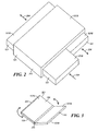
- the electronic device 100 further includes a touch-sensitive display 1018 that essentially comprises one side of the electronic device 100.
- the electronic device 100 has three native components 101 that each also comprises at least a touch-sensitive display 1018.
- Each of these components 101 is able to be moved in and out of the housing 201 (as generally represented by the arrows denoted by reference numeral 204). More particularly, such a configuration permits the components 101 to be contained within the housing 201 in a non-deployed state. This configuration, in turn, greatly reduces the overall size and periphery of the overall platform and makes it easier for the user to, for example, carry or store the platform. This configuration also permits, however, the overall available display area to be considerably increased by moving the components 101 to a fully-deployed state.
- FIG. 3 illustrates an example where two components 101 are each physically connected to the electronic device 100 by a respective hinge 301 disposed along opposing edges of the electronic device's housing 201.
- One or both primary sides of any of these respective elements can include a touch-sensitive display 1018. So configured the overall platform can again achieve a concise, easily-carried, and easily-stored form factor while also supporting the capability to offer a variety of user interface options including options that make use of an increased display area that can be achieved by unfolding the components 101 away from the electronic device 100.
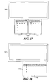
- FIG. 4-1 and FIG. 4-2 illustrate an example of a portable electronic device 100 having four moveable components 101 which include sliding components 401 and 402, also known as sliders, and rotating or pivoting components 403 and 404, also known as flips.
- the moveable components 101 are shown in non-deployed positions in FIG. 4-1 and in deployed positions in FIG. 4-2 . Any one or more of the moveable components 101 may be deployed at a given time.
- Different user interfaces may be incorporated into the moveable components 101, including physical interfaces such as keyboards, microphones, and speakers, and virtual interfaces, such as touch-sensitive displays.
- a touch-sensitive display may be part of each of the sliders 401 and 402
- a speaker and optional display may be part of one flip 403
- a microphone and a keyboard either physical or virtual, may be integrated into the other flip 404.
- a touch-sensitive display can be provided on a main segment 405 of the electronic device 100.
- one or more of the moveable components 101 may be opened or deployed.
- a number of application icons 406 are displayed on one slider 402, and information related to an application is displayed on one of the components 101 or the main segment 405 when the icon for the application is invoked by dragging onto the component 101 or main segment or when another method of launching is applied.
- a calendar application may be displayed on one slider 401
- a music player may be displayed on the upper flip 403
- an email interface may be displayed on the main segment 405.
- Each of the displayed applications may be executed concurrently or only a selected application or applications may be running at any given time.
- Flexible ribbon cable, fiber optics, customized hinges, and so forth facilitate movement while maintaining an ability to provide power and exchange data between the components 101 and the main segment 405.
- the form factor of the combined electronic device 100 and these components 101 can be varied in numerous ways to accommodate a wide variety of user preferences or requirements.
- functionality of such a platform can be based or driven, at least in part, in dependency upon a particular current form factor or relative motion of these respective elements.
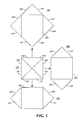
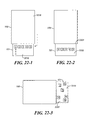
- FIG. 5 An alternative form factor for a portable electronic device 100 is shown in FIG. 5 .
- This form factor includes a plurality of moveable components 101 in the shape of triangles that rotate or pivot into a deployed position either from the front or back of a main segment 505 of the portable electronic device 100.
- a larger square results, which may be utilized in the diamond orientation shown or rotated 45 degrees such that the presentation of the device is square to a user.
- any one or more of the moveable components 101 may be deployed at a given time.
- Different user interfaces may be incorporated into the moveable components 101, including physical interfaces such as keyboards, microphones, and speakers, and well as virtual interfaces such as touch-sensitive displays.
- a touch-sensitive display may be part of each of the side flips 502 and 504 and the main segment 505, a speaker and optional display may be part of an upper flip 501, and a microphone and an optional display may be integrated into a lower flip 503.
- one or more of the moveable components 101 may be opened or deployed.
- a phone application or music player may be automatically and responsively launched.
- an email application or game may be automatically and responsively launched such that a keyboard or game controls are displayed, respectively.
- a number of application icons can be automatically displayed on one flip 502, for example.
- Information related to an application is displayed on another of the components 101 or the main segment 505 when the icon for the application is dragged onto the component 101 or main segment or another method of launching is applied.
- a calendar application may be displayed on one slider 504, a music player may be displayed on the upper flip 501, and an email interface may be displayed on the main segment 505.
- the displays may be foldable displays, such that a permanent or relatively permanent fold in the display, such as an organic light-emitting diode (OLED)-based display, facilitates displaying information up to the edge of the housing of the movable components and the main segment, thus minimizing the effect of the housing and increasing available display area by eliminating visible non-display areas.
- OLED organic light-emitting diode
- a plurality of components 101 are shown in a cooperative configuration in FIG. 6 .
- information may be displayed across one or more displays as corresponds to these components 101 (where the display of a single document or image is coordinated among the processors of these devices) or an application such as a game can be controlled across all the coordinated devices, and so forth.
- the larger overall display area achieved by combining a plurality of such components may be utilized to display more aspects of a game, e.g., a larger geographic area for a war game.
- larger objects may be displayed across multiple devices.
- One or more sensors 601 may be distributed along the outer perimeter of each of the components 101 to assess the alignment of these devices with respect to one another to facilitate coordination of the display of information and control of information and input to the devices.
- the sensors 601 may detect, for example, relative position and configuration of the devices with respect to one another, movement of the devices with respect to one another in any dimension, and proximity of a device, such as a separate device 602 that is entering the range of the group of devices.
- sensors 601 include accelerometers, optical sensors (optionally paired with optical emitters), magnetic sensors such as Hall effect sensors, light sensors, proximity sensors, pressure sensors, near-field communication devices, and so forth.
- a plurality of optical emitters such as light emitting diodes, may each emit a different color, for example by emission color or color filter, or a pattern of light, such as a coded sequence of blinking light, in a known distribution to facilitate detection of the relative orientation of devices.
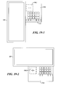
- FIG. 7 depicts a component 101 having several examples of contact or coupling interfaces. These examples can be used to couple the component 101 with one or more electronic devices 100 and/or one or more other components 101.
- one or more exposed electrical contacts 701 can be disposed along one or more outer surfaces of the component 101 that are configured to make an appropriate electrical contact when placed alongside a corresponding electronic device 100. These electrical contacts 701 can electrically couple to the component's internal circuitry to permit the provision or receipt of electrical signals or power.
- the component 101 may have one or more magnetic elements 702 and 703 that are disposed on an exterior surface of the component 101 or that are disposed within the component 101.
- These magnetic elements 702 and 703 can comprise standard magnets or can comprise, for example, electromagnets that can be selectively switched on and off (or otherwise modulated) by the component 101.
- such a component 101 can have a plug-like member 704 that includes electrical conductors to facilitate electrically coupling the component 101 to a corresponding electronic device 100.
- the coupling between the component 101 and the electronic device 100 may be physical as well as logical.
- FIG. 8 depicts an electronic device 100 having a housing 201 that includes one or more communicative interfaces to interact with such components 101.
- This communicative interface can include, for example, one or more exposed electrical contacts 801 that are sized, configured, and located to interact appropriately with one or more corresponding components 101.
- the temporary coupling between the component 101 and the electronic device 100 can comprise a magnetically-based coupling.
- the component 101 can have one or more magnetic elements 702 and 703.
- the electronic device 100 can include one or more magnetically-responsive sensors 802 that are configured to respond to the magnetic energy of the component's magnetic elements.
- These magnetically-responsive sensors 802 can permit the electronic device 100 to detect whether a component 101 is disposed proximal to the electronic device 100. These magnetically-responsive sensors 802 can also permit the electronic device 100 to determine a particular positioning of the component 101 with respect to the electronic device 100. This proximity/position information can serve to trigger a logical coupling between the electronic device 100 and the component 101 using, for example, a short-range radio frequency-based wireless communication approach. This configuration will also accommodate communicating information via modulation of the magnetic elements and detecting that modulation via the magnetically-responsive sensors 802.
- the electronic device 100 can also optionally include one or more slots 803 formed therein to receive the aforementioned optional plug-like members 704. These elements can be configured to provide, for example, a friction fit that tends to hold the component 101 in place with respect to the electronic device 100.
- This slot 803 can further include other retaining mechanisms or even locking mechanisms.
- Such a slot can also include electrical-magnetic (or optical) interfaces to facilitate logically coupling active elements of the component 101 to counterpart elements of the electronic device 100.
- slots 803 When the housing 201 of the electronic device 100 has a plurality of these optional slots 803, one or more of these additional slots 803 can be located on other edges of the housing 201. Such slots 803 can serve to receive additional components 101 or can serve to provide the user with a variety of possibilities as to where the user attaches a given component 101 to the electronic device 100. When providing a plurality of slots 803, the slots may all be essentially identically configured or may differ in order to accommodate differently-sized or configured plug-like members.
- the aforementioned optional slot 803 may itself be selectively movable as shown in FIG. 9 .
- a movable component 902 that includes the slot 803 may slide along the length of a corresponding recess 901 in a side edge of the housing 201.
- the electronic device 100 can comprise any of a wide variety of devices including both programmable, multi-purpose devices as well as fixed-purpose devices.
- the electronic device 100 may comprise, at least in part, a portable communication device.
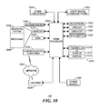
- FIG. 10 A block diagram of an example of an electronic device such as the portable electronic device 100 is shown in FIG. 10 .
- a component 101 as referred to herein may be an electronic device with all or part of the same functionality of the portable electronic device 100; accordingly, this description of the portable electronic device 100 will also be understood to apply as well to the component 101.
- the portable electronic device 100 includes a processor 1002 that controls the overall operation of the portable electronic device 100. Communication functions, including data and voice communications, are performed through a communication subsystem 1004. The communication subsystem receives messages from and sends messages to a wireless network 1050.
- the wireless network 1050 may be any type of wireless network, including, but not limited to, data wireless networks, voice wireless networks, and networks that support both voice and data communications.
- a power source 1042 such as one or more rechargeable batteries or a port to an external power supply, powers the electronic device 100.
- the processor 1002 interacts with other elements, such as Random Access Memory (RAM) 1008, memory 1010, a display 1012 with a touch-sensitive overlay 1014 operably coupled to an electronic controller 1016 that together comprise an optional touch-sensitive display 1018, one or more actuators 1020, one or more force sensors 1022, an auxiliary input/output (I/O) subsystem 1024, a data port 1026, a speaker 1028, a microphone 1030, short-range communication subsystem 1032, and other device subsystems 1034.
- RAM Random Access Memory
- memory 1010 e.g., RAM 1008
- display 1012 with a touch-sensitive overlay 1014 operably coupled to an electronic controller 1016 that together comprise an optional touch-sensitive display 1018, one or more actuators 1020, one or more force sensors 1022, an auxiliary input/output (I/O) subsystem 1024, a data port 1026, a speaker 1028, a microphone 1030, short-range communication subsystem 1032, and other device subsystems 1034.
- One or more user interfaces are provided. Input via a graphical user interface is provided via the touch-sensitive overlay 1014.
- the processor 1002 interacts with the touch-sensitive overlay 1014 via the electronic controller 1016.
- Information such as text, characters, symbols, images, icons, and other items that may be displayed or rendered on a portable electronic device, is displayed on the touch-sensitive display 1018 via the processor 1002.
- the processor 1002 may interact with an accelerometer 1036 that may be utilized to detect direction of gravitational forces or gravity-induced reaction forces.
- the portable electronic device 100 may utilize a Subscriber Identity Module or a Removable User Identity Module (SIM/RUIM) card 1038 for communication with a network, such as the wireless network 1050.
- SIM/RUIM Removable User Identity Module
- user identification information may be programmed into memory 1010.
- the portable electronic device 100 includes an operating system 1046 and software programs, applications, or components 1048 that are executed by the processor 1002 and are typically stored in a persistent, updatable store such as the memory 1010. Additional applications or programs may be loaded onto the portable electronic device 100 through the wireless network 1050, the auxiliary I/O subsystem 1024, the data port 1026, the short-range communications subsystem 1032, or any other suitable subsystem 1034.
- Memory 1010 may comprise a non-transitory storage media that stores executable code, when executed, causes one or more of functions or actions as described herein.
- a received signal such as a text message, an e-mail message, or web page download is processed by the communication subsystem and input to the processor 1002.
- the processor 1002 processes the received signal for output to the display 1012 and/or to the auxiliary I/O subsystem 1024.
- a subscriber may generate data items, for example e-mail messages, which may be transmitted over the wireless network 1050 through the communication subsystem.
- the speaker 1028 outputs audible information converted from electrical signals
- the microphone 1030 converts audible information into electrical signals for processing.
- the touch-sensitive display 1018 may be any suitable touch-sensitive display, such as a capacitive, resistive, infrared, surface acoustic wave (SAW) touch-sensitive display, strain gauge, optical imaging, dispersive signal technology, acoustic pulse recognition, and so forth, as known in the art.
- a capacitive touch-sensitive display includes a capacitive touch-sensitive overlay 1014.
- the overlay 1014 may be an assembly of multiple layers in a stack including, for example, a substrate, a ground shield layer, a barrier layer, one or more capacitive touch sensor layers separated by a substrate or other barrier, and a cover.
- the capacitive touch sensor layers may comprise any suitable material, such as indium tin oxide (ITO).
- One or more touches may be detected by the touch-sensitive display 1018.
- the processor 1002 may determine attributes of the touch, including a location of a touch.
- Touch location data may include data for an area of contact or data for a single point of contact, such as a point at or near a center of the area of contact.
- the location of a detected touch may include x and y components, e.g., horizontal and vertical components, respectively, with respect to one's view of the touch-sensitive display 1018.
- the x location component may be determined by a signal generated from one touch sensor
- the y location component may be determined by a signal generated from another touch sensor.
- a signal is provided to the controller 1016 in response to detection of a touch.
- a touch may be detected from any suitable input member, such as a finger, thumb, appendage, or other objects, for example, a stylus, pen, or other pointer, depending on the nature of the touch-sensitive display 1018. Multiple simultaneous touches may be detected.
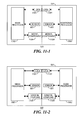
- FIG. 11-1 A block diagram of a portable electronic device 100 with a movable component 101 is shown in FIG. 11-1 .
- the electronic device 100 includes within its housing a controller that is part of the processor 1002 as shown in FIG. 11-1 .
- This controller can alternatively comprise, for example, a discrete controller such as a circuit or other electronic element.
- a controller can comprise a fixed-purpose hard-wired platform or can comprise a partially or wholly programmable platform.
- preferences information may be stored in memory in the electronic device or alternatively in optional memory in the component 101.
- This preferences information can, for example, comprise information that maps particular application functions to corresponding physical configurations of the electronic device in combination with the component 101.
- the user interface(s), when present, can include essentially any input or output mechanism.
- Options include touch-sensitive and non-touch-sensitive displays of any kind, alphanumeric-entry mechanisms (such as keyboards, keypads, and the like), cursor-control mechanisms (such as a mouse, joystick, trackball, touchpad, or the like), voice recognition modules, and so forth.
- the user interface can also facilitate input entry from a user to enter, for example, information that maps particular application functions to corresponding physical configurations of the electronic device 100 and component(s) 101, which information, when entered, can be stored in memory.
- a controller may be configured to detect and, as appropriate, respond to one or more trigger events.
- a trigger event can comprise a received communication such as, but not limited to, a received wireless voice or data communication.
- a trigger can comprise an input from the user interface, such as selection of an icon that results in opening an application, such as a media player, or a file for an application, such as a music or video file.
- a trigger in a given application can comprise a time-based event, such as a calendar event, a duration of time expiring, a time of day, a day of the month arriving, and so forth.
- the electronic device 100 may open one or more components 101 to render usable a speaker and microphone, and the phone application may optionally be displayed on the display.
- the electronic device 100 can comprise one or more transceivers that are part of the aforementioned communication subsystem 1004.
- This transceiver can include both short-range transceivers (such as, but not limited to, Bluetooth-compatible transceivers, so-called Wi-Fi-compatible transceivers, light-based transceivers, and so forth) and long-range transceivers (including, but not limited to, cellular telephony devices).
- short-range transceivers such as, but not limited to, Bluetooth-compatible transceivers, so-called Wi-Fi-compatible transceivers, light-based transceivers, and so forth
- long-range transceivers including, but not limited to, cellular telephony devices.
- the electronic device 100 can further comprise a receive-only wireless receiver and/or a transmit-only wireless transmitter.
- the electronic device 100 can be configured to take a responsive action upon detecting that one or more movable components 101 have moved or are moving relative to another part of the electronic device 100.
- the electronic device 100 can further optionally include one or more sensors 601 that operably couple to the controller to provide, for example, data regarding a sensed configuration or state.
- a sensor can, at least in part, detect, for example, that a movable component 101 is moving or has moved to a new position relative to another part of the electronic device 100.
- sensors 601 include accelerometers, optical sensors, magnetic sensors such as Hall effect sensors, light sensors, proximity sensors, pressure sensors, near field communication devices, and so forth.
- One or more sensors 601 can be configured to sense a present physical configuration of a plurality of elements, such as one part of the electronic device 100 and one or more movable components 101 that are part of the electronic device 100.
- the relevant part of the electronic device 100 may be, for example, an edge, perimeter, or other part of the housing that has different orientations with respect to the component 101 Depending on the position and movement of the component 101.
- the movement includes, for example, various modes of articulation including, but not limited to, pivoting, rotating, folding/unfolding/bending, sliding, telescoping/elongating, realigning, separation, or combination thereof.
- Sensors 601 may be disposed in the component 101, the electronic device 100, or both.
- One or more sensors 601 can be configured to sense one or more kinds of physical interaction between the electronic device 100 and one or more movable components 101.
- This sensing capability can comprise, for example, sensing one or more characteristics of movement to thereby detect such physical interaction.
- characteristics of movement include a direction of movement of, for example, a movable component 101 with respect to another part of the electronic device 100, orientation of one element with respect to another element such as the orientation of the electronic device 100 with respect to a given movable component 101, an identification of which element moved from amongst a plurality of monitored elements, a type of motion, and so forth.
- Non-limiting examples might include a physical reorientation of, for example, the movable component 101 with respect to the electronic device 100, a pivoting movement between the movable component 101 and the electronic device 100, a sliding movement between the movable component 101 1 and the electronic device 100, a momentary change in physical proximity of the movable component 101 with respect to the electronic device 100, and so forth.
- sensors that serve to detect a particular physical state. Examples include, but are certainly not limited to, detecting that a given movable component is presently not deployed, detecting that a given movable component is presently fully deployed, detecting that a given movable component is presently partially (but not fully) deployed, detecting which area or areas of the electronic device 100 presently interact with the movable component 101, and so forth.
- the senor(s) 601 employed can vary. Depending upon the particular physical interaction/characteristic that one wishes to detect in a given application setting, the sensor(s) 601 employed can vary. Depending upon circumstances, magnetic field-based sensors, light-based sensors, color-based sensors, acceleration-based sensors, power/radiation-level-based sensors, location-based sensors, optical sensors, pressure sensors, and so forth, or any combination thereof, may be utilized.
- the electronic device 100 can further optionally comprise one or more locks 1101.
- this lock(s) 1101 is controlled by the controller and serves to lock one or more movable components 101 in place with respect to the electronic device 100.
- These teachings also accommodate, however, permitting a user to manipulate the lock 1101 using a hand or a tool in order to effect the locking and unlocking of the element.
- Various locking mechanisms are known in the art and require no further description here.
- the sensor 601 can serve to sense a particular locked/unlocked state of such a lock 1101.
- these teachings are well designed to employ in conjunction with a component 101 that can move with respect to an electronic device 100. In some cases, that movement may be initiated by the physical manipulations of an end user or by some other external source.
- the present teachings also accommodate the electronic device 100 causing such movement.
- the electronic device 100 can optionally include one or more motive components 1104 that are positioned and configured to cause movement of the electronic device 100 and the component 101 with respect to one another.
- the motive component 1104 can interface with and make use of gears, cams, pistons, and so forth to effect the appropriate motion.
- the motive component can employ elements such as motors, actuators, solenoids, electromagnets, piezoelectric devices, relays, voice coils, hydraulic actuators, electroactive polymers, and so forth.
- This movable component 101 typically (though not necessarily always) comprises at least one user interface.
- This user interface(s) can receive input from the user, provide output to the user, or both.
- Examples of user interfaces include displays, touch-sensitive displays, touchpads, optical joysticks, trackballs, physical keys or buttons, and so forth.
- the user interface of the component 101 may logically couple (using logical coupler 1105, for example) to the electronic device's controller or may logically couple to a controller that comprises a part of the movable component 101, such as an additional processor 1102, a discrete controller, or other control device.
- the controller of the moveable component 101 can be configured to carry out one or more of the movable component actions or functions as are described herein.
- the controller of the moveable component 101 may carry out one or more of the movable-component actions or functions as are described herein or may operate in conjunction with control associated with the electronic device controller.
- the movable component 101 can include other hardware and/or software to support a given application.
- the movable component 101 can optionally include memory that can store information that can be selectively provided to the electronic device 100.
- information can comprise, for example, one or more identification (ID) codes that can be a unique identification code that correlates to the movable component 101 to differentiate a particular movable component from other movable components.
- ID identification
- the memory can also store other information such as profile or preferences information associated with the movable component 101.
- the profile may include, but not be limited to, information such as one or more usage contexts for the discrete component 101, identification of an end user, local resources that are accessible via the component 141, and so forth.
- the profile may optionally include a mapping that includes one or more application functions that are performed when a component is placed in a particular position with respect to a portable electronic device and/or another component, and one or more components and component positions that are engaged when an application function is performed.
- a mapping that includes one or more application functions that are performed when a component is placed in a particular position with respect to a portable electronic device and/or another component, and one or more components and component positions that are engaged when an application function is performed.
- the phone application may be opened by the device 100.
- a media file such as a song is selected
- a component including a speaker is deployed.
- Components including a keyboard and display are deployed when an email is received in another example.
- the movable component can include one or more wireless transceivers, receivers, or transmitters that are part of the aforementioned communication subsystem 100d.
- This transceiver can include essentially any short-range or long-range transceiver technology.
- Such a transceiver can, for example, wirelessly communicate with a corresponding element of the electronic device 100, with a counterpart element of another movable component 101 as may be presently (or imminently) logically coupled to the electronic device 100, or with a remote access point (such as a Wi-Fi hotspot located in the general area), a resource (such as an information or service server that is accessible via a network such as the Internet), and so forth.
- the various elements (and others as appropriate) of the movable component 101 can be operably coupled amongst themselves or can be individually operably coupled to, for example, the electronic device's controller.
- at least one of the elements of the component 101 logically couples to the electronic device's controller via a corresponding logical coupling 1105.
- a logical connection or logical coupling 1105 includes at least one communication path shared by two or more devices to convey data. Examples of data include, but are not limited to, instructions, status signals, state-based messages, informational content such as images for display, and so forth.
- the logical connection or logical coupling 1105 may utilize a communication protocol that supports, for example, handshaking, authentication, error detection or correction, or the like.
- This logical connection/coupling 1105 may comprise a part of, or be distinct from, any physical coupling between the component 101 and the electronic device 100.
- the logical connection/coupling 1105 may comprise a wired connection, a wireless connection, or any combination thereof.
- the movable components 101 offer any of a variety of enhanced, supplemented, or expanded user-interface opportunities.
- These opportunities can include both fixed-purpose user interfaces, for example, audio-signal drivers and transducers, physical buttons, switches, or keys, displays, image-capture devices, and so forth, as well as flexible or programmable user interfaces such as touch-sensitive displays.
- these teachings facilitate such an electronic device 100 to respond in a variety of ways to presence/movement/orientation of one or more such movable components 101.
- These examples are intended to serve an illustrative purpose and are not to be taken as representing any limitations by their specificity nor are these examples to be considered an exhaustive listing of all relevant possibilities as to the scope and application of these teachings.
- FIG. 12 A flowchart illustrating a method of moving a movable component is shown in FIG. 12 .
- the method is performed by the electronic device 100 that is a portable electronic device in this example.
- the method may be carried out at least in part by software executed, for example, by the processor 1002. Coding of software for carrying out such a method is within the scope of a person of ordinary skill in the art given the present description.
- the method may contain additional or fewer processes than shown and/or described, and may be performed in a different order.
- Computer-readable code executable by at least one processor of the portable electronic device to perform the method may be stored in a computer-readable medium, such as a non-transitory computer-readable medium.
- the portable electronic device detects 1201 a trigger event.
- this trigger event can comprise any of a variety of trigger events including asynchronous events such as a received wireless communication or received user input as well as synchronous events such as any of a variety of time-based events.
- This detection process 1201 optionally comprises monitoring for any of a plurality of different trigger events.
- this process can accommodate any of a variety of responses.
- responses can include temporal multitasking (pursuant to which the portable electronic device conducts other tasks before returning to again monitor for a trigger event) as well as continually looping back to essentially continuously monitor for the trigger event(s).
- Detection of the trigger event can facilitate automatic movement of a movable component 101.
- a present suitability of automatically moving such a component 101 may be determined 1202. This determination can be based, for example, upon use of one or more sensors 601 that detect one or more relevant circumstances or states. Examples include a light sensor that detects, for example, when the electronic device 100 is disposed within or under a purse, pocket, or backpack, a force or proximity sensor to detect, for example, when movement of the given movable component 101 is likely to, or is, encountering an obstacle, and so forth.
- This suitability determination can occur prior to automatically moving the component 101, while automatically moving the component 101, or both.
- the process of determining suitability may be repeated until suitability is confirmed.
- a timeout or prompt may return the process to 1201.
- the electronic device 100 In response to detection 1201 of the trigger event, the electronic device 100 automatically moves 1203 at least one component 101.
- this movement can comprise automatically moving a component 101 that comprises a part of or is otherwise native to the portable electronic device 100.
- this movement can comprise automatically moving multiple components 101, either both at about the same time or one component at a time.
- the component 101 might comprise, for example, a housing, a battery cover, or a memory card cover.
- This automatic movement can vary based on a given application setting or preference.
- this automatic movement can comprise moving the component via articulation, such as via pivoting, rotating, sliding, bending, telescoping, elongating, realigning, separating, and so forth.
- the movement can serve, for example, to move the component from a non-deployed state, where, for example, the component is partially or fully contained within the portable electronic device, to a partially or wholly-deployed state, or vice versa, where, for example, the component is automatically moved back to a previous position.
- this automatic movement of the component 101 with respect to the remainder of the portable electronic device 100 can be a complete response. In other cases, further responsive actions may be performed.
- the portable electronic device can additionally optionally automatically 1204 change application functionality of the portable communication device based on or in response to having moved the component 101.
- the movable component comprises an alphanumeric keypad
- automatic deployment of the component to fully reveal the alphanumeric keypad can also lead to automatically initiating a particular application or application functionality that is specifically correlated to the present availability of such an alphanumeric keypad.
- the portable electronic device when the portable electronic device receives a phone call when in a completely closed state, the appropriate components of the portable electronic device are automatically moved or opened to facilitate use of the speaker 1028 and microphone 1030.
- the user when the user selects the media player, appropriate components of the portable electronic device are automatically moved or opened to facilitate use of the speaker 1028, display of information regarding the available or selected music, and media player controls (for example, a touch-sensitive display 1018 showing options for media player controls).
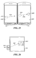
- the component 101 need not comprise a native component of the electronic device 100, such as shown in FIG. 11-2 . In many such cases (though certainly not all), the component 101 may be physically as well as logically coupled to the electronic device 100, for example, to accommodate an end user's present needs.
- a first portable electronic device 100 is coupled to a peer portable electronic device 100 that also comprises, for the purposes of this example, a discrete component 101 with respect to the first portable electronic device 100. (For this illustrative example it is presumed that both of these portable electronic devices 100 are configured as shown in FIG. 10 .)
- profile information may be stored in memory 1010 of either device.
- This profile information can correlate to unique identification codes that correspond to various components 101, for example, when such components 101 are non-native to the electronic device 100.
- the profiles can provide any of a variety of information, including, but not limited to, a class of user interface that characterizes the component 101, a particular discrete component instance, a particular display edge (when, for example, the component 101 includes a display such as a touch-sensitive display 1018 or other display), a resource that is accessible via the component 101 (including both resources that are local to the component 101 such as particular programs, data stores, user interface forms, and so forth as well as resources that are remote to the component 101 and that may be accessed via a communication capability of the component 101), a usage context for the discrete device, identification of a particular end user, identification of a group of users, and so forth.
- Sensors 601 may be disposed along an outer perimeter of each device 100 to facilitate detection of the relation of other electronic devices, for example, to coordinate a display of information on multiple displays.
- One or more sensors may optionally be disposed on each side of the device 100, e.g., along each of the four sides of a generally rectangular-shaped device 100.
- Identification information that correlates to specific interfaces, surfaces, or attachment edges of the component 101 may be stored, for example, in memory 1010.
- each connection interface can be provided with a different connection identifier.
- the electronic device 100 can use such connection identifiers to identify a particular attachment configuration. Identification of the attachment configuration can permit the electronic device 100 to adjust its use of the component 101 accordingly.
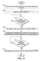
- FIG. 13 A flow diagram illustrating a method of changing application functionality based on such configuration information is shown in FIG. 13 .
- the method is performed by an electronic device 100 that is a portable electronic device in this example.
- the method may be carried out at least in part by software executed, for example, by the processor 1002. Coding of software for carrying out such a method is within the scope of a person of ordinary skill in the art given the present description.
- the method may contain additional or fewer processes than shown and/or described, and may be performed in a different order.
- Computer-readable code executable by at least one processor of the portable electronic device to perform the method may be stored in a computer-readable medium, such as a non-transitory computer-readable medium.
- Pursuant to this example application functions are mapped 1301 to physical configurations of the electronic device 100.
- information may be default information or information entered into the electronic device 100 via an appropriate user interface, such as via menu entry, in response to a prompt, and so forth, or any combination thereof.
- Information including one or more application functions mapped to corresponding physical configurations of the electronic device may be entered during set-up of the electronic device or at any other time.
- the electronic device may receive the information via user input and the information may be stored in a user profile. This information can supplement, substitute for, or otherwise serve in the absence of default mapping information that might otherwise apply.
- the mapping information is stored in the electronic device 100, for example, in memory 1010.
- the electronic device 100 can optionally store one or more preferences, such as application functions corresponding physical configurations of the electronic device 100, at 1302. In such a case, the particular application function that is automatically performed can be determined by accessing the preferences information.
- a change in the physical configuration of the electronic device 100 is detected, at 1303.
- the electronic device 100 has at least two physical configurations.
- a native movable component 101 can be moved respective to the electronic device 100 between a first physical configuration and a second physical configuration.
- a first physical configuration may include, for example, when a native component 101 is in a non-deployed position, while a second physical configuration may include when that native component 101 is in a deployed position.
- the electronic device may detect or receive 1304 input, for example, that occurs when a user asserts or utilizes a user interface, that comprises a part of the electronic device 100 or of the component 101.
- the user interface may comprise, for example, a physical button, key, or switch, trackpad, optical joystick, trackball, or other navigation device, touch-sensitive display or other touch-sensitive input, sound-activated input device, and so forth.
- This detection may comprise detecting, for example, that this particular user assertion occurs at least partially simultaneously with the detected change in physical configuration.
- This detection might also comprise detecting that the assertion occurs prior to, or subsequent to, the detected change in physical configuration within, for example, some predetermined period of time, such as 1 second, five seconds, 1 minute, or such other period of time that may be useful in a given application setting.
- the electronic device 100 In response to detecting the change in physical configuration (or optionally, the user assertion) the electronic device 100 automatically performs 1305 an application function.
- this response can comprise altering, for example, by supplementing, limiting, or even prohibiting present application functionality.
- the phone application may be opened on the electronic device, such that a virtual keyboard with numbers for dialing a call is displayed.
- this physical configuration may result in opening a video application when a meeting in the calendar indicates a video conference.
- game controls may be displayed on the two components 101, and a game interface is displayed on the electronic device 100.
- this configuration may result in an email application opening when an email is received by the electronic device 100.
- an alteration of present application functionality can comprise, at least in part, automatically moving at least a portion of the application's user interface from the electronic device 100 to the component 101 (or vice versa).
- the electronic device 100 can include one or more sensors 601 that can detect, for example, a particular orientation of the electronic device 100.
- the application function that is automatically initiated, changed, or prohibited can optionally or additionally be determined based, at least in part, on the detected orientation of the electronic device 100.
- the action of responsively performing an application function can be undertaken following expiration of at least a predetermined amount of time (such as, for example, 1 second, 5 seconds, or some other relevant duration of time) following detection of the change in physical configuration.
- a predetermined amount of time such as, for example, 1 second, 5 seconds, or some other relevant duration of time
- This time-based condition can help to assure, for example, that a presently-detected physical configuration is not merely a transitory configuration while the user moves the movable component 101 to a final physical configuration.
- Application functionality may be automatically performed in response to detecting a particular physical configuration of the electronic device with respect to a native movable component.
- automatically prohibiting 1305 a particular application function of the electronic device 100 may be performed, at least in part, based on the detected physical configuration of the electronic device 100.
- opening of a media player or phone application may be prohibited.
- a prompt may be provided to a user when application functionality is prohibited, including, for example, information regarding a configuration change that would permit opening of the application.
- the electronic device 100 can automatically provide new functionality upon detecting a change in the physical configuration of the electronic device 100. Such an approach can be optionally supplemented by detecting 1306 a subsequent change in the physical configuration of the electronic device 100 and responsively automatically 1307 initiating, supplementing, limiting, or prohibiting another application function of the electronic device 100.
- FIG. 14 A flow diagram illustrating a method of changing application functionality based on the configuration of an electronic device and a discrete device appears in FIG. 14 .
- the discrete device is a physically discrete or separate movable component 101 that may be, for example, a plug-in physical or virtual keyboard, a touch-sensitive display, a navigation device such as an optical trackpad or joystick, and so forth.
- the method is performed by an electronic device 100that is a portable electronic device in this example.
- the method may be carried out at least in part by software executed, for example, by the processor 1002. Coding of software for carrying out such a method is within the scope of a person of ordinary skill in the art given the present description.
- the method may contain additional or fewer processes than shown and/or described, and may be performed in a different order.
- Computer-readable code executable by at least one processor of the portable electronic device to perform the method may be stored in a computer-readable medium, such as a non-transitory computer-readable medium.
- a change in physical configuration of a discrete device with respect to an electronic device 100 is detected 1401.
- Detection can comprise, for example, detecting movement of the discrete device with respect to the electronic device, detecting the orientation of a physical coupling of the discrete device to the electronic device, detecting an area of operable coupling between the discrete device and the electronic device, such as which side, or where along a particular side, of the electronic device the discrete device is presently proximal, and so forth.
- Application functionality of the electronic device 100 is changed 1403 based, at least in part, on information received 1402 by the electronic device 100 from the discrete device.
- This information can comprise, for example, the aforementioned unique identification code.
- Such a code depending upon the needs of the particular application setting, can uniquely identify the discrete device with respect to other discrete devices or can identify the discrete device as belonging to a unique class, group, or category of discrete devices, such as comprising a particular type of display, audio transducer, keyboard, and so forth.
- This change can further comprise changing the application functionality based on such information as may have been provided by one or more other discrete devices that are also operably coupled to the electronic device 100.
- Change in application functionality may more advantageously leverage, for example, the relative capabilities of all of the discrete devices that are presently operably coupled to the electronic device 100.
- this change of application functionality can comprise running, simultaneously on both the electronic device 100 and the discrete device, an application that runs unitarily on both devices or in coordination on both devices, where the operation of the application is shared. For example, one device may control display of information while the other device receives and interprets input from both devices.
- the detected change in physical configuration can optionally comprise, at least in part, detecting an orientation of the discrete device with respect to the electronic device and performing 1404 a function, e.g., via the electronic device 100, based on that detected orientation.
- An area of coupling between the devices may be accounted for when performing a function.
- the area of coupling may include, for example, identification of a side of one device that is coupled to a side of the other electronic device, identification of a corner of one device coupling with a corner or side of the other electronic device, and so forth.
- detecting the change in physical configuration takes into account detecting an area of operable coupling between the discrete device and the electronic device 100, a function is performed 1405 based on the detected area of operable coupling.
- the electronic device 100 can be configured with a lock 1101 to facilitate physically locking the discrete device to the electronic device 100.
- the discrete device may be locked 1406 to the electronic device in response to detecting the change in physical configuration, which locking may occur automatically upon detecting.
- prohibiting physical unlocking 1407 of the discrete device may be engaged, for example, until at least one predetermined condition is met.
- This predetermined condition might comprise, for example, concluding a particular process by the electronic device 100, such as logically decoupling the electronic device 100 from the component 101, completing an electronic exchange of data between the electronic device 100 and the discrete device, and so forth.
- This capability can further include automatically unlocking the discrete device from the electronic device 100 when the at least one predetermined condition is met.
- More than one discrete device may be coupled to a single electronic device 100.
- controlling 1408 the operable coupling of one or more discrete devices to the electronic device 100 which may optionally be controlled automatically.
- Controlling 1408 the physical locking of one or more of these discrete devices to the electronic device 100 can be based upon the detected physical configuration. This ability to prevent unlocking can serve, for example, to prohibit removing a given discrete device that is useful or critical to the present functionality of the electronic device 100.
- Locking and unlocking may also be applied to the logical coupling between one or more discrete devices and the electronic device 100.
- teachings also accommodate using a locking capability to prevent a given component 101 from becoming physically attached to the electronic device 100.
- an unknown or un-trusted component can be prevented from attaching to the electronic device 100 physically, logically, or both.
- a component 101 that is inadequately resourced or provisioned to carry out a necessary functionality, e.g., inadequate memory or processor speed, may be prevented from attaching.
- the detected change in physical configuration serves to effect an automatic change in the application functionality of the electronic device 100.
- response to the detection of a change in physical configuration by automatically changing 1409 application functionality of at least one of one or more discrete devices and the electronic device may be provided.
- FIG. 15 A flow diagram illustrating a method of performing functions in response to physical interactions between devices is shown in FIG. 15 .
- the devices may be an electronic device 100 and one or more physically discrete or separate movable components 101 such as described above.
- the method is performed by an electronic device 100 that is a portable electronic device in this example and optionally the discrete device.
- the method may be carried out at least in part by software executed, for example, by the processor 1002. Coding of software for carrying out such a method is within the scope of a person of ordinary skill in the art given the present description.
- the method may contain additional or fewer processes than shown and/or described, and may be performed in a different order.
- Computer-readable code executable by at least one processor of the portable electronic device to perform the method may be stored in a computer-readable medium, such as a non-transitory computer-readable medium.
- Monitoring may comprise, for example, monitoring the passage of time in general. Monitoring may alternatively comprise, for example, determining an amount of time that passes subsequent to first detecting, or confirmation of detection of the start or completion of a physical interaction, or determining a time of continuous movement between the devices.
- a physical interaction can be detected 1502 between a first device, e.g., the movable component 101, and a second device, e.g., the electronic device 100, where the two devices are logically coupled to one another.
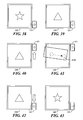
- the physical interaction comprises one of a plurality of physical interactions that involve movement of at least one of the first and second device with respect to one another. Examples include sliding the devices along adjacent sides, tapping the devices together, rotating one device with respect to the other in the same plane or different planes, placing the devices face to face, e.g., display to display, and so forth. Any suitable number of interactions may be successfully utilized, including one or more interactions, which may be provided in series, in parallel, or any combination thereof. See FIG. 28 through FIG. 43 for illustrated examples.
- monitoring time may comprise the monitoring of the amount of time spent between physical interactions and/or monitoring the amount of time spent on each physical interaction.
- One or more functions are performed 1504, for example, automatically or in response to the detecting, by the electronic device 100 and/or the discrete device that participates in the physical interaction.
- the performance of a function can comprise, for example, compensating a display of information on the movable component 101 to account for a physical misalignment between the movable component 101 and the electronic device 100.
- Such an electronic device 100 can be configured to functionally respond to a series of movements between the electronic device 100 and one or more movable devices 101 that may be native to, or discrete from, the electronic device 100. This ability to respond to a series of movements facilitates the movable component-based gestures to serve as input, such as functional triggers, for the electronic device 100. Such a capability can offer numerous advantages and opportunities in various application settings.
- FIG. 16 A flow diagram illustrating a method of detecting deployment of components is shown in FIG. 16 .
- the method is performed by an electronic device 100 that is a portable electronic device in this example.
- the method may be carried out at least in part by software executed, for example, by the processor 1002. Coding of software for carrying out such a method is within the scope of a person of ordinary skill in the art given the present description.
- the method may contain additional or fewer processes than shown and/or described, and may be performed in a different order.
- Computer-readable code executable by at least one processor of the portable electronic device to perform the method may be stored in a computer-readable medium, such as a non-transitory computer-readable medium.
- the movable components 101 can comprise one or more user interfaces.
- the movable component 101 is deployable between at least a non-deployed position and a fully-deployed position.
- the movable component may be engaged in one or more positions between non-deployed and fully deployed.
- the user interface of the movable component 101 may be at least partially hidden from the view of the person using the electronic device 100 in an ordinary manner when the movable component is in the non-deployed position.
- Deployment of the movable component(s) 101 is detected 1601.
- This detection can comprise, for example, utilizing a sensor 601 as shown in FIG. 11 , which may be referred to in this example as a deployment sensor.
- the deployment sensor 601 may be a proximity sensor that detects the position of the movable component 101, for example, by determining a distance to the movable component 101 from the proximity sensor.
- At least one of the first user interface and the device user interface are configured or reconfigured 1602 based, at least in part, on an ergonomic circumstance of deployment of the movable component 101.
- An ergonomic circumstance includes, but is not limited to, a request, need, or situation to maintain or increase the user's comfort or to maintain or reduce the user's fatigue while using the electronic device 100.
- Different ergonomic situations include, but are not limited to, standing 2-handed use, sitting 2-handed use, walking left- or right-handed use, and right-handed or left-handed use with one or more movable components deployed.
- the method of claim 16 may be applied to one or more movable components 101.
- Ergonomic situations may be detected by any combination of an accelerometer or other sensor such as a proximity sensor or light sensor to detect movement or how the device 100 is being held; data input, such as touch data including touch shapes or touch history, suggesting use by a single hand; input through a menu or selection option to identify an ergonomic circumstance; and so forth.
- Selection options may be displayed on the movable component 101 and/or the electronic device 100 to facilitate the ergonomic circumstance, such as nearer to one hand, at an angle, spread along multiple radii in part of a circle, by user profile for the ergonomic circumstance, and so forth.
- FIG. 17 and FIG. 18 provide one illustrative example of an ergonomic circumstance.
- the electronic device 100 includes two movable components 101. Also in this example both of the movable components 101 include a touch-sensitive display 1018.
- both of the movable components 101 are fully deployed.
- the electronic device 100 accordingly automatically utilizes these two movable components to display, across both components 101, a QWERTY keyboard via the touch-sensitive displays of both components 101.
- a first one of the movable components 1701 displays the left-hand side of the QWERTY keyboard while the second movable component 1702 displays the right-hand side of the QWERTY keyboard.
- the first movable component 1701 is shown in a non-deployed state, leaving only the second movable component 1702 in the deployed position.
- the electronic device 100 automatically uses the touch-sensitive display 1018 of the second movable component 1702 to display the complete QWERTY keyboard using, for example, smaller key caps, rather than only one half of the keyboard.
- FIGS. 19 and 20 provide more illustrative examples of ergonomic-user cases.
- the movable component 1702 with a touch-sensitive display 1018 and touchpad-based cursor control user interface 1902 is shown in a position deployed by sliding the component 101 out, for example, for a right-handed only use.
- FIG. 19-1 shows the display of a QWERTY keyboard and touchpad-based cursor control in portrait mode
- FIG. 19-2 shows the same component 101 configured in landscape mode. Deploying the left-sided touch-sensitive display 1701 rather than the right-side touch-sensitive display 1702 and using the former to display a QWERTY keyboard in a similar manner can provide a similar configuration more suited for many left-handed users.
- the movable component 101 is withdrawn within the electronic device 100 to a non-deployed position.
- the electronic device 100 here has a touch-sensitive display 1018 that displays, in part, a cursor 2001 that the user can move about the display in order to make selections and effect other desired actions.
- the touch-sensitive display 1018 has a portion thereof that is demarked and utilized as a touchpad-based cursor-control user interface 1902.
- the electronic device 100 can take advantage of this opportunity to potentially improve the ergonomics of this operating paradigm by moving the touchpad-based cursor-control user interface 1902 to the touch-sensitive display 1018 of the movable component 101. This move leaves additional room on the display 1018 of the electronic device 100 that can be repurposed in other ways.
- the movable component 101 is deployed such that the movable component 101 extends outwardly laterally from a first side of the electronic device 100.
- the electronic device 100 reacts to this deployment state by utilizing the touch-sensitive display 1018 of the movable component 101 to again present the right-hand side of a QWERTY keyboard (the left-hand side of the keyboard being presented via the electronic device's touch-sensitive display 1018).
- the electronic device 100 upon sliding (or rotating or otherwise moving) the movable component 101 to a different side of the electronic device's housing, the electronic device 100 automatically changes the displayed content for at least some of the keys that appear on the movable component's display 1018.
- the displayed keys comprise a numeric keyboard rather than an alphabetic keyboard.
- FIG. 22-2 and FIG. 22-3 illustrate another example of functional changes as a consequence of a reorientation.
- component 101 with touch-sensitive display 1018 is shown combined with an electronic device 100.
- the electronic device 100 has a portrait orientation.
- the component 101 has a landscape orientation and is combined with the electronic device 100 on a bottom edge of the electronic device 100.
- the edge is referenced with the numeral 2201.
- the electronic device reacts to this configuration state and presents a set of virtual buttons organized horizontally in a single row utilizing the component's 101 touch-sensitive display 1018.
- FIG. 22-3 the combined electronic device 100 and component 101 are rotated 90 degrees counter clockwise from the orientation shown in FIG. 22-2 .
- the electronic device 100 has a landscape orientation whereas FIG. 22-2 shows the electronic device 100 having a portrait orientation.
- the component 101 has a portrait orientation whereas FIG. 22-2 shows the component 101 having a landscape orientation.
- the component 101 remains combined with the electronic device 100 along the edge 2201. In this example, the electronic device 100 and component 101 remain logically and physically coupled during the rotation.
- the electronic device 100 reacts to the new orientation resulting from the rotation and presents a new set of virtual keys on the component's 101 touch-sensitive display 1018.
- FIG. 22-2 there are 5 virtual buttons organized along a horizontal axis whereas in FIG. 22-3 there are 6 virtual buttons organized in a random pattern.
- the set of virtual buttons depicted in FIG. 22-3 include some of the virtual buttons depicted in FIG. 22-2 in addition to some new virtual buttons that were added as a result of the rotation and that are not present in FIG. 22-2 . Also, in this example some of the virtual buttons in FIG. 22-2 were removed as a consequence of the rotation.
- the combined electronic device 100 and the component 101 may be separated during the rotation. They may or may not remain logically coupled during the rotation.
- functional and ergonomic changes may be affected once the reorientation is complete (where the new configuration state remains constant for some predetermined time). Functional and ergonomic changes may occur while the reorientation is ongoing and during the transition from one configuration state to another.
- the virtual buttons in the provided example may be disabled during rotation preventing their activation during rotation.
- the movable component 101 utilized a touch-sensitive display as the primary user interface.
- the movable component 101 can provide physical keys having key caps that can be selected using, for example, internal illumination, active displays as key caps, or the like.
- the same described approach can be applied to facilitate changing the key-cap content based on how the deployable component is deployed at a given time to thereby maintain or improve the ergonomics of using the device.
- FIG. 23 depicts an example where the electronic device 100 and the component 101 each comprise a smartphone. Each smartphone presently operates independently of the other, as illustrated by the star 2301 on the display 2302 of the electronic device 100 and the triangle 2303 on the display 2304 of the component 101. As the two elements 100 and 101 are moved towards one another as indicated by the arrow 2305, the component 101 and the electronic device 100 become sufficiently close to one another to logically couple as described herein. As shown in FIG. 24 , when such proximity-based coupling occurs, the electronic device 100 automatically responds by providing altered functionality, illustrated by the oval 2401 displayed across both displays 2302 and 2304.
- a touch in the form of a swipe begins on one display 2302 and continues onto the other display 2304 of these logically-coupled smartphones.
- a touch is detected on the display 2302 of the electronic device 100 at a starting point 2501 and is further detected as a swipe as the touch moves across the surface of the display 2302 towards the electronic device 101 as indicated by the arrow 2502.
- the touch is detected on the display 2304 of the second smartphone 101 at the location denoted by reference numeral 2503.
- These logically-coupled smartphones recognize the continuation of the swipe that began on the display 2302 of the first electronic device 100 and continued on the display 2304 of the second electronic device 101. Accordingly, as the swipe continues across the display 2304 of the second electronic device 101, as represented by the arrow 2504, and ends at a concluding point 2505, the two-part swipe can be recognized and treated as a single swipe as though the swipe were accomplished using a single display.
- Control of the swipe is handed off or changed, for example, between the processor 1102 of the first device 100 and the processor 1102 of the second device 101 when the touch is continued on the second device 101.
- One or both processors 1102 may determine that the touch continued from one device 100 to the other device 101.
- one of the processors 1102 may be selected to process touch data for both devices, for example, when the devices 100, 101 logically couple. Touch data is exchanged between the devices 100, 101 to provide control for the touch input.
- FIG. 26 illustrates the leveraging of this two-device swiping capability.
- the electronic device 100 comprises a smartphone and the component 101 comprises a tablet/pad.
- the electronic device 100 displays a small image 2601 that a user moves for display on the component 101 by using a two-device swipe 2602 such as described above.
- the image 2603 displayed on the component 101 automatically enlarges to take advantage of the relatively larger display space of the component 101.
- This process can be reversed, when a larger image displayed on the component 101 is dragged to the electronic device 100 by a swipe and automatically reduced in size to better fit the electronic device's smaller display.
- an image may be dragged from a touch-sensitive display 1018 of one device 100 to a touch-sensitive display 1018 of another device 101.
- FIG. 27 depicts another example of the flexibility of the present teachings.
- both the electronic device 100 and the component 10 comprise tablet computers.
- the tablets are positioned nearby one another. While in proximity, the tablets logically couple as described herein, and the electronic device 100 also senses the nearby configuration and orientation with the component 101.
- the electronic device 100 uses this information, and optionally other information received from the component 101, to enter a calendar sharing operation.
- This sharing includes combining schedule events from two calendars, one stored on the electronic device 100 and the other stored on the component 101, and presenting a single combined calendar schedule, though not necessarily a same view of that combined calendar schedule on the displays of both tablets and reflecting the combined schedule events appropriately on each display.
- a common schedule event 2702 is visible in full details on both displays. Schedule events that are confidential or exclusive to one calendar can be masked.
- one schedule event 2704 in particular is from the calendar stored on the electronic device 100. That event 2704 is displayed in full detail on the electronic device's 100 display 2701. That schedule event 2704 is masked (as referenced by the numeral 2705), however, on the component's display 2703.
- FIGS. 28 through 31 illustrate one such example.
- an electronic device 100 and a component 101 are disposed in close physical proximity to one another and are logically coupled.
- FIG. 29 and FIG. 30 illustrate these two devices 100,101 as separated and subsequently returned to close physical proximity to one another.
- This separation-and-return action serves as a gesture that the electronic device 100 and/or the component 101 recognize and that causes one or both such devices 100 and 101 to perform a function or assume new (or supplemental) functionality, such as illustrated in FIG. 31 .
- Recognition of a specific gesture may rely, at least in part, upon the distance of the movement apart from one another (denoted in FIG. 29 by "X") and/or completing the gesture within some predetermined period of time, such as one or two seconds.
- FIGS. 32 through 35 illustrate another example of a gesture.
- the electronic device 100 and the component 101 are physically proximal to one another and logically coupled to one another as shown in FIG. 32 .
- the electronic device 100 is moved along an edge of the component 101 to form a gesture, e.g., back and forth along the edge of the component.
- a gesture e.g., back and forth along the edge of the component.
- the two devices 100,101 present the same physical formation as before the gesture, one or both of these devices 100, 101 now have new (or at least modified) functionality based upon that gesture.
- the gesture may provide other input to the devices 100, 101, such as transferring information between the devices 100, 101, scrolling through information on one of the devices, changing the displayed information, and so forth.
- FIGS. 36 through 38 illustrate that the initial physical/logical connection between the electronic device 100 and the component 101 can include such a gesture.
- the component 101 reaches a place of rest (shown in FIG. 38 ) by sliding along one edge of the electronic device 100.
- the component 101 sliding along this edge is recognized as a gesture that provides an input, for example changing functionality, performing a function, and so forth.
- FIGS. 39 through 43 illustrate that such gestures can be combined with touch-based gestures.
- the component 101 slides along one edge of the electronic device 100 ( FIG. 39 and FIG. 40 ) and a swipe from one location to another location 4100 across the touch-sensitive display of the electronic component 101 ( FIG. 41 ) is detected.
- the component 101 slides back along the electronic device's edge ( FIG. 42 ), e.g., the component 101 is detected as returned to its starting position or a position near the starting position ( FIG. 43 ).
- This entire sequence of events serves as a multi-modality gesture that provides input that may, for example, change the functionality such as described above.
- the meaning (and/or recognition) of a given gesture may optionally be further specified by the timing of the various movements that are involved with the gesture. For example, two gestures that otherwise appear identical can have different meanings depending upon how long a time the user takes to complete parts or all of the gesture.
- teachings can be employed in a wide variety of application settings and with a myriad of device/component configurations. These teachings are highly scalable and can be employed with a great number and type of devices and movable components as well as an essentially unlimited number of user interfaces, degrees of motion, orientation and deployment configurations, and so forth.
- Deploying components based on ergonomic circumstance and configuring a user interface based at least in part on the ergonomic circumstance helps reduce user wear and fatigue.
- an electronic device such as a portable communication device
- moves a component of the device in response to detection of a trigger event a user is provided quicker and automatic access to the elements of the device to handle the trigger event, such as opening or deploying components with a speaker and microphone when a phone call is received.
- Suitability of such movement may be determined prior to and/or during movement to inhibit movement or further movement to prevent damage or breakage of the device and its movable elements.
- Application functions may be performed or functionality modified, including launching applications and providing various user interfaces, upon detection of or in response to a physical configuration of an electronic device, including configuration of native components of the device and physical or logical coupling with another discrete device such as another peer device or accessory such as a keyboard.
- Application functionality may be changed and/or input provided to the devices in response to detecting a physical configuration of a discrete device with respect to an electronic device, thereby providing a user with a more flexible interface when multiple devices are utilized.
- One or more physical interactions between devices provide input to the devices as well as coordination of functionality, including display of information and operation of applications among one or more devices.
- Such coordination and operation occurs automatically to provide faster and more flexible operation.
- a user may be provided with the ability to store preferences for the above features in a user profile or to engage a feature manually, e.g., through a menu or selection option.
Applications Claiming Priority (1)
| Application Number | Priority Date | Filing Date | Title |
|---|---|---|---|
| US13/251,848 US20130085705A1 (en) | 2011-10-03 | 2011-10-03 | Method and apparatus pertaining to automatically performing an application function of an electronic device based upon detecting a change in physical configuration of the device |
Publications (3)
| Publication Number | Publication Date |
|---|---|
| EP2579551A1 true EP2579551A1 (de) | 2013-04-10 |
| EP2579551A9 EP2579551A9 (de) | 2014-04-02 |
| EP2579551B1 EP2579551B1 (de) | 2015-08-26 |
Family
ID=44785598
Family Applications (1)
| Application Number | Title | Priority Date | Filing Date |
|---|---|---|---|
| EP11184846.1A Active EP2579551B1 (de) | 2011-10-03 | 2011-10-12 | Verfahren und Vorrichtung zur automatischen Durchführung einer Anwendungsfunktion einer elektronischen Vorrichtung basierend auf der Erkennung einer Änderung in der physischen Konfiguration der Vorrichtung |
Country Status (3)
| Country | Link |
|---|---|
| US (1) | US20130085705A1 (de) |
| EP (1) | EP2579551B1 (de) |
| CA (1) | CA2788192A1 (de) |
Families Citing this family (12)
| Publication number | Priority date | Publication date | Assignee | Title |
|---|---|---|---|---|
| US9851811B2 (en) * | 2012-02-20 | 2017-12-26 | Beijing Lenovo Software Ltd. | Electronic device and method for controlling the same |
| US10673691B2 (en) * | 2012-03-24 | 2020-06-02 | Fred Khosropour | User interaction platform |
| KR20140027579A (ko) * | 2012-07-06 | 2014-03-07 | 삼성전자주식회사 | 단말기의 사용자인증 수행 장치 및 방법 |
| KR102011360B1 (ko) * | 2012-09-10 | 2019-10-21 | 삼성전자주식회사 | 디바이스에서 어플리케이션을 실행하는 방법 및 그 장치 |
| DE102012223007A1 (de) * | 2012-12-13 | 2014-06-18 | Hilti Aktiengesellschaft | Handgeführtes oder halbstationäres Werkzeuggerät und Verfahren zum Betreiben eines derartigen Werkzeuggeräts |
| US20140282068A1 (en) | 2013-03-15 | 2014-09-18 | SingTel Idea Factory Pte. Ltd. | Systems and methods for transferring of objects among mobile devices based on pairing and matching using actions and/or gestures associated with the mobile device |
| EP2818985B1 (de) * | 2013-06-28 | 2021-05-12 | Nokia Technologies Oy | Feld zur schwebende Eingabe |
| KR20150027891A (ko) * | 2013-08-30 | 2015-03-13 | 삼성전자주식회사 | 전자 장치들을 이용한 콘텐트 표현 방법 및 장치 |
| US9424322B2 (en) * | 2013-11-25 | 2016-08-23 | Sony Corporation | Digital sticky note |
| US9417704B1 (en) | 2014-03-18 | 2016-08-16 | Google Inc. | Gesture onset detection on multiple devices |
| JP6783003B1 (ja) * | 2019-11-01 | 2020-11-11 | 将也 実広 | 電子機器、プログラムおよび制御方法 |
| US11296942B1 (en) | 2021-03-11 | 2022-04-05 | International Business Machines Corporation | Relative device placement configuration |
Citations (6)
| Publication number | Priority date | Publication date | Assignee | Title |
|---|---|---|---|---|
| WO2006023058A1 (en) * | 2004-08-11 | 2006-03-02 | Motorola Inc. | Passivation of external keys of a communication device in a closed position |
| US20070004451A1 (en) * | 2005-06-30 | 2007-01-04 | C Anderson Eric | Controlling functions of a handheld multifunction device |
| US20090258638A1 (en) * | 2008-04-10 | 2009-10-15 | Eun Young Lee | Mobile terminal using variable menu icons |
| US20100099463A1 (en) * | 2008-10-16 | 2010-04-22 | Jun-Hee Kim | Mobile terminal having touch sensor-equipped input device and control method thereof |
| US20100110010A1 (en) * | 2007-07-30 | 2010-05-06 | Lg Electronics Inc. | Mobile terminal using touch screen and method of controlling the same |
| US20110081923A1 (en) * | 2009-10-02 | 2011-04-07 | Babak Forutanpour | Device movement user interface gestures for file sharing functionality |
Family Cites Families (6)
| Publication number | Priority date | Publication date | Assignee | Title |
|---|---|---|---|---|
| JPH10214128A (ja) * | 1997-01-30 | 1998-08-11 | Yazaki Corp | ジョイスティック型多機能コントローラ |
| US6005551A (en) * | 1997-04-25 | 1999-12-21 | Microsoft Corporation | Offline force effect rendering |
| KR20040091106A (ko) * | 2002-03-08 | 2004-10-27 | 미쓰비시덴키 가부시키가이샤 | 이동체 통신장치와, 이동체 통신장치의 표시제어방법 |
| US7388578B2 (en) * | 2004-07-01 | 2008-06-17 | Nokia Corporation | Touch display PDA phone with slide keypad |
| US7512427B2 (en) * | 2005-09-02 | 2009-03-31 | Nokia Corporation | Multi-function electronic device with nested sliding panels |
| KR101608764B1 (ko) * | 2009-07-14 | 2016-04-04 | 엘지전자 주식회사 | 이동 단말기 및 이것의 디스플레이 제어 방법 |
-
2011
- 2011-10-03 US US13/251,848 patent/US20130085705A1/en not_active Abandoned
- 2011-10-12 EP EP11184846.1A patent/EP2579551B1/de active Active
-
2012
- 2012-08-31 CA CA2788192A patent/CA2788192A1/en not_active Abandoned
Patent Citations (6)
| Publication number | Priority date | Publication date | Assignee | Title |
|---|---|---|---|---|
| WO2006023058A1 (en) * | 2004-08-11 | 2006-03-02 | Motorola Inc. | Passivation of external keys of a communication device in a closed position |
| US20070004451A1 (en) * | 2005-06-30 | 2007-01-04 | C Anderson Eric | Controlling functions of a handheld multifunction device |
| US20100110010A1 (en) * | 2007-07-30 | 2010-05-06 | Lg Electronics Inc. | Mobile terminal using touch screen and method of controlling the same |
| US20090258638A1 (en) * | 2008-04-10 | 2009-10-15 | Eun Young Lee | Mobile terminal using variable menu icons |
| US20100099463A1 (en) * | 2008-10-16 | 2010-04-22 | Jun-Hee Kim | Mobile terminal having touch sensor-equipped input device and control method thereof |
| US20110081923A1 (en) * | 2009-10-02 | 2011-04-07 | Babak Forutanpour | Device movement user interface gestures for file sharing functionality |
Also Published As
| Publication number | Publication date |
|---|---|
| EP2579551B1 (de) | 2015-08-26 |
| CA2788192A1 (en) | 2013-04-03 |
| US20130085705A1 (en) | 2013-04-04 |
| EP2579551A9 (de) | 2014-04-02 |
Similar Documents
| Publication | Publication Date | Title |
|---|---|---|
| EP2579551B1 (de) | Verfahren und Vorrichtung zur automatischen Durchführung einer Anwendungsfunktion einer elektronischen Vorrichtung basierend auf der Erkennung einer Änderung in der physischen Konfiguration der Vorrichtung | |
| EP2579556A1 (de) | Verfahren und Vorrichtung für die automatische Funktion basierend auf einer erkannten Interaktion zwischen Vorrichtungen | |
| EP2579550A1 (de) | Verfahren und Vorrichtung zum automatischen Verschieben einer Komponente, die einen Teil einer tragbaren elektronischen Vorrichtung umfasst | |
| JP6407206B2 (ja) | 可撓性ディスプレイを有するカバーアタッチメント | |
| US11429275B2 (en) | Electronic device with gesture-based task management | |
| JP5827337B2 (ja) | 携帯電子機器をドッキングするためのユーザインタフェースに関するシステムと方法 | |
| TWI429268B (zh) | 以雙視窗作為介面之行動裝置 | |
| US9116663B2 (en) | Method for changing device modes of an electronic device connected to a docking station and an electronic device configured for same | |
| US10474312B2 (en) | Operation method of portable terminal | |
| KR102015913B1 (ko) | 이동 단말기 및 그 제어방법 | |
| KR20160013748A (ko) | 휴대 전자기기 및 그것의 제어방법 | |
| KR20100054369A (ko) | 단말기 및 그 제어 방법 | |
| EP2996012B1 (de) | Mobiles endgerät und steuerungsverfahren dafür | |
| KR102043150B1 (ko) | 이동 단말기 | |
| KR20100030968A (ko) | 단말기 및 그의 메뉴 디스플레이 방법 | |
| KR20130076482A (ko) | 이동 단말기 및 그 동작 제어 방법 | |
| EP2579560A1 (de) | Verfahren und Vorrichtung zur automatischen Konfiguration der Benutzerschnittstelle einer anwendbaren Komponente | |
| KR101978169B1 (ko) | 이동 단말기 및 이의제어방법 | |
| KR20130005321A (ko) | 이동 단말기 및 그 제어방법 | |
| KR20210113880A (ko) | 이동 단말기, 이동 단말기를 구비한 전자 장치, 그리고 전자 장치의 제어 방법 | |
| KR20100042405A (ko) | 단말기 및 그 제어 방법 | |
| EP2607982B1 (de) | Verfahren zum Ändern von Vorrichtungsmodi einer elektrischen Vorrichtung, die an einer Docking-Station angeschlossen ist und dafür konfigurierte elektronische Vorrichtung | |
| EP2579553A1 (de) | Verfahren und Vorrichtung zum reaktiven Ändern der Anwendungsfunktion auf einer elektronischen Vorrichtung | |
| KR20100054944A (ko) | 입력 시스템 및 그 제어 방법 | |
| KR102214117B1 (ko) | 이동 단말기 및 그의 후면 입력부 운용방법 |
Legal Events
| Date | Code | Title | Description |
|---|---|---|---|
| PUAI | Public reference made under article 153(3) epc to a published international application that has entered the european phase |
Free format text: ORIGINAL CODE: 0009012 |
|
| 17P | Request for examination filed |
Effective date: 20111012 |
|
| AK | Designated contracting states |
Kind code of ref document: A1 Designated state(s): AL AT BE BG CH CY CZ DE DK EE ES FI FR GB GR HR HU IE IS IT LI LT LU LV MC MK MT NL NO PL PT RO RS SE SI SK SM TR |
|
| AX | Request for extension of the european patent |
Extension state: BA ME |
|
| RAP1 | Party data changed (applicant data changed or rights of an application transferred) |
Owner name: BLACKBERRY LIMITED |
|
| RAP1 | Party data changed (applicant data changed or rights of an application transferred) |
Owner name: BLACKBERRY LIMITED |
|
| 17Q | First examination report despatched |
Effective date: 20140310 |
|
| GRAP | Despatch of communication of intention to grant a patent |
Free format text: ORIGINAL CODE: EPIDOSNIGR1 |
|
| INTG | Intention to grant announced |
Effective date: 20150402 |
|
| GRAS | Grant fee paid |
Free format text: ORIGINAL CODE: EPIDOSNIGR3 |
|
| GRAA | (expected) grant |
Free format text: ORIGINAL CODE: 0009210 |
|
| AK | Designated contracting states |
Kind code of ref document: B1 Designated state(s): AL AT BE BG CH CY CZ DE DK EE ES FI FR GB GR HR HU IE IS IT LI LT LU LV MC MK MT NL NO PL PT RO RS SE SI SK SM TR |
|
| REG | Reference to a national code |
Ref country code: GB Ref legal event code: FG4D |
|
| REG | Reference to a national code |
Ref country code: CH Ref legal event code: EP |
|
| REG | Reference to a national code |
Ref country code: AT Ref legal event code: REF Ref document number: 745824 Country of ref document: AT Kind code of ref document: T Effective date: 20150915 |
|
| REG | Reference to a national code |
Ref country code: IE Ref legal event code: FG4D |
|
| REG | Reference to a national code |
Ref country code: DE Ref legal event code: R096 Ref document number: 602011019096 Country of ref document: DE |
|
| REG | Reference to a national code |
Ref country code: FR Ref legal event code: PLFP Year of fee payment: 5 |
|
| REG | Reference to a national code |
Ref country code: AT Ref legal event code: MK05 Ref document number: 745824 Country of ref document: AT Kind code of ref document: T Effective date: 20150826 |
|
| REG | Reference to a national code |
Ref country code: LT Ref legal event code: MG4D |
|
| PG25 | Lapsed in a contracting state [announced via postgrant information from national office to epo] |
Ref country code: GR Free format text: LAPSE BECAUSE OF FAILURE TO SUBMIT A TRANSLATION OF THE DESCRIPTION OR TO PAY THE FEE WITHIN THE PRESCRIBED TIME-LIMIT Effective date: 20151127 Ref country code: LT Free format text: LAPSE BECAUSE OF FAILURE TO SUBMIT A TRANSLATION OF THE DESCRIPTION OR TO PAY THE FEE WITHIN THE PRESCRIBED TIME-LIMIT Effective date: 20150826 Ref country code: NO Free format text: LAPSE BECAUSE OF FAILURE TO SUBMIT A TRANSLATION OF THE DESCRIPTION OR TO PAY THE FEE WITHIN THE PRESCRIBED TIME-LIMIT Effective date: 20151126 Ref country code: FI Free format text: LAPSE BECAUSE OF FAILURE TO SUBMIT A TRANSLATION OF THE DESCRIPTION OR TO PAY THE FEE WITHIN THE PRESCRIBED TIME-LIMIT Effective date: 20150826 Ref country code: LV Free format text: LAPSE BECAUSE OF FAILURE TO SUBMIT A TRANSLATION OF THE DESCRIPTION OR TO PAY THE FEE WITHIN THE PRESCRIBED TIME-LIMIT Effective date: 20150826 |
|
| REG | Reference to a national code |
Ref country code: NL Ref legal event code: FP |
|
| PG25 | Lapsed in a contracting state [announced via postgrant information from national office to epo] |
Ref country code: AT Free format text: LAPSE BECAUSE OF FAILURE TO SUBMIT A TRANSLATION OF THE DESCRIPTION OR TO PAY THE FEE WITHIN THE PRESCRIBED TIME-LIMIT Effective date: 20150826 Ref country code: PL Free format text: LAPSE BECAUSE OF FAILURE TO SUBMIT A TRANSLATION OF THE DESCRIPTION OR TO PAY THE FEE WITHIN THE PRESCRIBED TIME-LIMIT Effective date: 20150826 Ref country code: SE Free format text: LAPSE BECAUSE OF FAILURE TO SUBMIT A TRANSLATION OF THE DESCRIPTION OR TO PAY THE FEE WITHIN THE PRESCRIBED TIME-LIMIT Effective date: 20150826 Ref country code: IS Free format text: LAPSE BECAUSE OF FAILURE TO SUBMIT A TRANSLATION OF THE DESCRIPTION OR TO PAY THE FEE WITHIN THE PRESCRIBED TIME-LIMIT Effective date: 20151226 Ref country code: ES Free format text: LAPSE BECAUSE OF FAILURE TO SUBMIT A TRANSLATION OF THE DESCRIPTION OR TO PAY THE FEE WITHIN THE PRESCRIBED TIME-LIMIT Effective date: 20150826 Ref country code: RS Free format text: LAPSE BECAUSE OF FAILURE TO SUBMIT A TRANSLATION OF THE DESCRIPTION OR TO PAY THE FEE WITHIN THE PRESCRIBED TIME-LIMIT Effective date: 20150826 Ref country code: PT Free format text: LAPSE BECAUSE OF FAILURE TO SUBMIT A TRANSLATION OF THE DESCRIPTION OR TO PAY THE FEE WITHIN THE PRESCRIBED TIME-LIMIT Effective date: 20151228 Ref country code: HR Free format text: LAPSE BECAUSE OF FAILURE TO SUBMIT A TRANSLATION OF THE DESCRIPTION OR TO PAY THE FEE WITHIN THE PRESCRIBED TIME-LIMIT Effective date: 20150826 |
|
| PG25 | Lapsed in a contracting state [announced via postgrant information from national office to epo] |
Ref country code: DK Free format text: LAPSE BECAUSE OF FAILURE TO SUBMIT A TRANSLATION OF THE DESCRIPTION OR TO PAY THE FEE WITHIN THE PRESCRIBED TIME-LIMIT Effective date: 20150826 Ref country code: EE Free format text: LAPSE BECAUSE OF FAILURE TO SUBMIT A TRANSLATION OF THE DESCRIPTION OR TO PAY THE FEE WITHIN THE PRESCRIBED TIME-LIMIT Effective date: 20150826 Ref country code: CZ Free format text: LAPSE BECAUSE OF FAILURE TO SUBMIT A TRANSLATION OF THE DESCRIPTION OR TO PAY THE FEE WITHIN THE PRESCRIBED TIME-LIMIT Effective date: 20150826 Ref country code: SK Free format text: LAPSE BECAUSE OF FAILURE TO SUBMIT A TRANSLATION OF THE DESCRIPTION OR TO PAY THE FEE WITHIN THE PRESCRIBED TIME-LIMIT Effective date: 20150826 Ref country code: IT Free format text: LAPSE BECAUSE OF FAILURE TO SUBMIT A TRANSLATION OF THE DESCRIPTION OR TO PAY THE FEE WITHIN THE PRESCRIBED TIME-LIMIT Effective date: 20150826 |
|
| REG | Reference to a national code |
Ref country code: DE Ref legal event code: R097 Ref document number: 602011019096 Country of ref document: DE |
|
| PG25 | Lapsed in a contracting state [announced via postgrant information from national office to epo] |
Ref country code: LU Free format text: LAPSE BECAUSE OF FAILURE TO SUBMIT A TRANSLATION OF THE DESCRIPTION OR TO PAY THE FEE WITHIN THE PRESCRIBED TIME-LIMIT Effective date: 20151012 Ref country code: RO Free format text: LAPSE BECAUSE OF FAILURE TO SUBMIT A TRANSLATION OF THE DESCRIPTION OR TO PAY THE FEE WITHIN THE PRESCRIBED TIME-LIMIT Effective date: 20150826 |
|
| REG | Reference to a national code |
Ref country code: CH Ref legal event code: PL |
|
| PG25 | Lapsed in a contracting state [announced via postgrant information from national office to epo] |
Ref country code: MC Free format text: LAPSE BECAUSE OF FAILURE TO SUBMIT A TRANSLATION OF THE DESCRIPTION OR TO PAY THE FEE WITHIN THE PRESCRIBED TIME-LIMIT Effective date: 20150826 |
|
| PLBE | No opposition filed within time limit |
Free format text: ORIGINAL CODE: 0009261 |
|
| STAA | Information on the status of an ep patent application or granted ep patent |
Free format text: STATUS: NO OPPOSITION FILED WITHIN TIME LIMIT |
|
| REG | Reference to a national code |
Ref country code: IE Ref legal event code: MM4A |
|
| PG25 | Lapsed in a contracting state [announced via postgrant information from national office to epo] |
Ref country code: CH Free format text: LAPSE BECAUSE OF NON-PAYMENT OF DUE FEES Effective date: 20151031 Ref country code: LI Free format text: LAPSE BECAUSE OF NON-PAYMENT OF DUE FEES Effective date: 20151031 |
|
| 26N | No opposition filed |
Effective date: 20160530 |
|
| PG25 | Lapsed in a contracting state [announced via postgrant information from national office to epo] |
Ref country code: SI Free format text: LAPSE BECAUSE OF FAILURE TO SUBMIT A TRANSLATION OF THE DESCRIPTION OR TO PAY THE FEE WITHIN THE PRESCRIBED TIME-LIMIT Effective date: 20150826 |
|
| REG | Reference to a national code |
Ref country code: FR Ref legal event code: PLFP Year of fee payment: 6 |
|
| PG25 | Lapsed in a contracting state [announced via postgrant information from national office to epo] |
Ref country code: IE Free format text: LAPSE BECAUSE OF NON-PAYMENT OF DUE FEES Effective date: 20151012 |
|
| PG25 | Lapsed in a contracting state [announced via postgrant information from national office to epo] |
Ref country code: BE Free format text: LAPSE BECAUSE OF FAILURE TO SUBMIT A TRANSLATION OF THE DESCRIPTION OR TO PAY THE FEE WITHIN THE PRESCRIBED TIME-LIMIT Effective date: 20150826 |
|
| PG25 | Lapsed in a contracting state [announced via postgrant information from national office to epo] |
Ref country code: BG Free format text: LAPSE BECAUSE OF FAILURE TO SUBMIT A TRANSLATION OF THE DESCRIPTION OR TO PAY THE FEE WITHIN THE PRESCRIBED TIME-LIMIT Effective date: 20150826 Ref country code: SM Free format text: LAPSE BECAUSE OF FAILURE TO SUBMIT A TRANSLATION OF THE DESCRIPTION OR TO PAY THE FEE WITHIN THE PRESCRIBED TIME-LIMIT Effective date: 20150826 Ref country code: HU Free format text: LAPSE BECAUSE OF FAILURE TO SUBMIT A TRANSLATION OF THE DESCRIPTION OR TO PAY THE FEE WITHIN THE PRESCRIBED TIME-LIMIT; INVALID AB INITIO Effective date: 20111012 |
|
| PG25 | Lapsed in a contracting state [announced via postgrant information from national office to epo] |
Ref country code: CY Free format text: LAPSE BECAUSE OF FAILURE TO SUBMIT A TRANSLATION OF THE DESCRIPTION OR TO PAY THE FEE WITHIN THE PRESCRIBED TIME-LIMIT Effective date: 20150826 |
|
| PG25 | Lapsed in a contracting state [announced via postgrant information from national office to epo] |
Ref country code: MT Free format text: LAPSE BECAUSE OF FAILURE TO SUBMIT A TRANSLATION OF THE DESCRIPTION OR TO PAY THE FEE WITHIN THE PRESCRIBED TIME-LIMIT Effective date: 20150826 |
|
| REG | Reference to a national code |
Ref country code: FR Ref legal event code: PLFP Year of fee payment: 7 |
|
| PG25 | Lapsed in a contracting state [announced via postgrant information from national office to epo] |
Ref country code: MK Free format text: LAPSE BECAUSE OF FAILURE TO SUBMIT A TRANSLATION OF THE DESCRIPTION OR TO PAY THE FEE WITHIN THE PRESCRIBED TIME-LIMIT Effective date: 20150826 Ref country code: TR Free format text: LAPSE BECAUSE OF FAILURE TO SUBMIT A TRANSLATION OF THE DESCRIPTION OR TO PAY THE FEE WITHIN THE PRESCRIBED TIME-LIMIT Effective date: 20150826 |
|
| REG | Reference to a national code |
Ref country code: FR Ref legal event code: PLFP Year of fee payment: 8 |
|
| PG25 | Lapsed in a contracting state [announced via postgrant information from national office to epo] |
Ref country code: AL Free format text: LAPSE BECAUSE OF FAILURE TO SUBMIT A TRANSLATION OF THE DESCRIPTION OR TO PAY THE FEE WITHIN THE PRESCRIBED TIME-LIMIT Effective date: 20150826 |
|
| PGFP | Annual fee paid to national office [announced via postgrant information from national office to epo] |
Ref country code: NL Payment date: 20231026 Year of fee payment: 13 |
|
| PGFP | Annual fee paid to national office [announced via postgrant information from national office to epo] |
Ref country code: GB Payment date: 20231027 Year of fee payment: 13 |
|
| PGFP | Annual fee paid to national office [announced via postgrant information from national office to epo] |
Ref country code: FR Payment date: 20231025 Year of fee payment: 13 Ref country code: DE Payment date: 20231027 Year of fee payment: 13 |