EP2579357B1 - Wiederaufladbare Batterie - Google Patents
Wiederaufladbare Batterie Download PDFInfo
- Publication number
- EP2579357B1 EP2579357B1 EP12178554.7A EP12178554A EP2579357B1 EP 2579357 B1 EP2579357 B1 EP 2579357B1 EP 12178554 A EP12178554 A EP 12178554A EP 2579357 B1 EP2579357 B1 EP 2579357B1
- Authority
- EP
- European Patent Office
- Prior art keywords
- plate
- terminal
- rechargeable battery
- plate terminal
- side wall
- Prior art date
- Legal status (The legal status is an assumption and is not a legal conclusion. Google has not performed a legal analysis and makes no representation as to the accuracy of the status listed.)
- Active
Links
Images


Classifications
-
- H—ELECTRICITY
- H01—ELECTRIC ELEMENTS
- H01M—PROCESSES OR MEANS, e.g. BATTERIES, FOR THE DIRECT CONVERSION OF CHEMICAL ENERGY INTO ELECTRICAL ENERGY
- H01M50/00—Constructional details or processes of manufacture of the non-active parts of electrochemical cells other than fuel cells, e.g. hybrid cells
- H01M50/50—Current conducting connections for cells or batteries
- H01M50/543—Terminals
- H01M50/564—Terminals characterised by their manufacturing process
- H01M50/567—Terminals characterised by their manufacturing process by fixing means, e.g. screws, rivets or bolts
-
- H—ELECTRICITY
- H01—ELECTRIC ELEMENTS
- H01M—PROCESSES OR MEANS, e.g. BATTERIES, FOR THE DIRECT CONVERSION OF CHEMICAL ENERGY INTO ELECTRICAL ENERGY
- H01M50/00—Constructional details or processes of manufacture of the non-active parts of electrochemical cells other than fuel cells, e.g. hybrid cells
- H01M50/10—Primary casings; Jackets or wrappings
- H01M50/147—Lids or covers
- H01M50/155—Lids or covers characterised by the material
- H01M50/157—Inorganic material
- H01M50/159—Metals
-
- H—ELECTRICITY
- H01—ELECTRIC ELEMENTS
- H01M—PROCESSES OR MEANS, e.g. BATTERIES, FOR THE DIRECT CONVERSION OF CHEMICAL ENERGY INTO ELECTRICAL ENERGY
- H01M50/00—Constructional details or processes of manufacture of the non-active parts of electrochemical cells other than fuel cells, e.g. hybrid cells
- H01M50/10—Primary casings; Jackets or wrappings
- H01M50/172—Arrangements of electric connectors penetrating the casing
- H01M50/174—Arrangements of electric connectors penetrating the casing adapted for the shape of the cells
- H01M50/176—Arrangements of electric connectors penetrating the casing adapted for the shape of the cells for prismatic or rectangular cells
-
- H—ELECTRICITY
- H01—ELECTRIC ELEMENTS
- H01M—PROCESSES OR MEANS, e.g. BATTERIES, FOR THE DIRECT CONVERSION OF CHEMICAL ENERGY INTO ELECTRICAL ENERGY
- H01M50/00—Constructional details or processes of manufacture of the non-active parts of electrochemical cells other than fuel cells, e.g. hybrid cells
- H01M50/50—Current conducting connections for cells or batteries
- H01M50/543—Terminals
- H01M50/547—Terminals characterised by the disposition of the terminals on the cells
- H01M50/55—Terminals characterised by the disposition of the terminals on the cells on the same side of the cell
-
- H—ELECTRICITY
- H01—ELECTRIC ELEMENTS
- H01M—PROCESSES OR MEANS, e.g. BATTERIES, FOR THE DIRECT CONVERSION OF CHEMICAL ENERGY INTO ELECTRICAL ENERGY
- H01M50/00—Constructional details or processes of manufacture of the non-active parts of electrochemical cells other than fuel cells, e.g. hybrid cells
- H01M50/50—Current conducting connections for cells or batteries
- H01M50/543—Terminals
- H01M50/552—Terminals characterised by their shape
- H01M50/553—Terminals adapted for prismatic, pouch or rectangular cells
-
- H—ELECTRICITY
- H01—ELECTRIC ELEMENTS
- H01M—PROCESSES OR MEANS, e.g. BATTERIES, FOR THE DIRECT CONVERSION OF CHEMICAL ENERGY INTO ELECTRICAL ENERGY
- H01M50/00—Constructional details or processes of manufacture of the non-active parts of electrochemical cells other than fuel cells, e.g. hybrid cells
- H01M50/50—Current conducting connections for cells or batteries
- H01M50/572—Means for preventing undesired use or discharge
- H01M50/574—Devices or arrangements for the interruption of current
- H01M50/583—Devices or arrangements for the interruption of current in response to current, e.g. fuses
-
- H—ELECTRICITY
- H01—ELECTRIC ELEMENTS
- H01M—PROCESSES OR MEANS, e.g. BATTERIES, FOR THE DIRECT CONVERSION OF CHEMICAL ENERGY INTO ELECTRICAL ENERGY
- H01M2200/00—Safety devices for primary or secondary batteries
- H01M2200/10—Temperature sensitive devices
- H01M2200/103—Fuse
-
- H—ELECTRICITY
- H01—ELECTRIC ELEMENTS
- H01M—PROCESSES OR MEANS, e.g. BATTERIES, FOR THE DIRECT CONVERSION OF CHEMICAL ENERGY INTO ELECTRICAL ENERGY
- H01M50/00—Constructional details or processes of manufacture of the non-active parts of electrochemical cells other than fuel cells, e.g. hybrid cells
- H01M50/50—Current conducting connections for cells or batteries
- H01M50/531—Electrode connections inside a battery casing
-
- Y—GENERAL TAGGING OF NEW TECHNOLOGICAL DEVELOPMENTS; GENERAL TAGGING OF CROSS-SECTIONAL TECHNOLOGIES SPANNING OVER SEVERAL SECTIONS OF THE IPC; TECHNICAL SUBJECTS COVERED BY FORMER USPC CROSS-REFERENCE ART COLLECTIONS [XRACs] AND DIGESTS
- Y02—TECHNOLOGIES OR APPLICATIONS FOR MITIGATION OR ADAPTATION AGAINST CLIMATE CHANGE
- Y02E—REDUCTION OF GREENHOUSE GAS [GHG] EMISSIONS, RELATED TO ENERGY GENERATION, TRANSMISSION OR DISTRIBUTION
- Y02E60/00—Enabling technologies; Technologies with a potential or indirect contribution to GHG emissions mitigation
- Y02E60/10—Energy storage using batteries
Definitions
- the invention relates generally to a rechargeable battery having a fuse unit on an external side thereof.
- a rechargeable battery is a battery that can be repeatedly charged and discharged, unlike a primary battery.
- a small sized rechargeable battery is used as a power supply for small electronic devices such as cellular phones, notebook computers, and camcorders, while a medium or large sized rechargeable battery is used as a power supply for driving motors in hybrid vehicles and the like.
- a rechargeable battery typically includes an electrode assembly around which a positive electrode and a negative electrode are wound, having a separator therebetween, a case having the electrode assembly embedded therein, a cap plate sealing an opening of a case, and an electrode terminal electrically connected to the electrode assembly by penetrating through the cap plate.
- an electrically weak portion in a line connecting the electrode assembly and the electrode terminal may melt and be disconnected when large current is charged or discharged.
- the rechargeable battery may further include a fuse portion.
- the fuse portion may cause generation of an arc in the disconnected portion if the disconnection gap is too small.
- the arc generated in the rechargeable battery may be applied to the electrolyte solution, and may thereby cause explosion or fire. That is, safety of the rechargeable battery may be deteriorated.
- JP 2011165611 discloses a battery having a fuse portion formed as part of a protective cap which is positioned on top of a battery terminal outside of a casing.
- JP 8315802 discloses an annular fuse element which is positioned within a terminal outside a battery.
- EP1422771 discloses a battery having a thermal fuse inside a concave section formed in a sealing plate which is closed off by an insulating plate.
- EP2360754 discloses a battery assembly comprising a bare cell and a protective circuit module which may include a fuse element.
- One or more embodiments seek to provide a rechargeable battery configured to maintain safety even after disconnection of a fuse portion and/or when an arc is generated.
- a first aspect of the invention provides a rechargeable battery according to claim 1.
- the electrode terminal may include a rivet terminal connecting the electrode assembly to the first plate terminal.
- the first plate may include a first through-hole corresponding to a through-hole of the first plate terminal, the first through-hole being configured to receive the rivet terminal, and the second plate includes a second through-hole corresponding to a through-hole of the second plate terminal and the first through-hole.
- a diameter of the second through-hole may be larger than a diameter of the first through-hole.
- the side wall of the first insulator member may include a lower side wall surrounding the first plate terminal and an upper side wall surrounding the second plate terminal.
- the lower side wall may include a lower coupling groove slide-ably coupled to a coupling protrusion of a side wall of the second insulator member, arranged opposite to the lower coupling groove.
- the upper side wall may include an upper coupling groove slide-ably coupled to a coupling frame of the second plate terminal, arranged opposite to the upper coupling groove.
- the second insulator member may include a side wall connected to the side wall of the first insulator member to surround the at least one other side surface of the first and second plates.
- the second insulator member may include a snap on an inner side of the side wall so as to be coupled to a snap groove of the first insulator member, arranged opposite to the snap.
- the second insulator member may include a slide groove on an inner side of the side wall so as to be slide-ably coupled to a coupling frame of the second plate terminal, arranged opposite to the slide groove.
- the fuse portion may protrude downward from the second plate terminal and the fuse portion has a width that is smaller than a width of the second plate terminal, and may be electrically connected to a receiving groove of the first plate terminal.
- the fuse portion may be surrounded by the second insulator member and is disposed on an inner side of the side wall.
- the electrode terminal may include a bolt provided in a through-hole of the second plate terminal.
- a head of the bolt may be supported between the second plate terminal and the second plate that face each other.
- a head of the bolt may be supported between the second plate terminal and the first plate terminal.
- a head of the bolt may be supported between the second plate terminal and the first insulator member.
- first and second plate terminals that are separated from each other on an external side of a cap plate and are connected using a fuse portion, safety of the rechargeable battery can be maintained even when an arc is generated after disconnection of the fuse portion.
- a rechargeable battery including an electrode assembly configured to charge and discharge current, a case in which the electrode assembly is installed, the case including an opening, a cap plate coupled to the opening of the case, an electrode terminal including a first sub-module and a second sub-module, wherein the first sub-module is arranged on a first side of the cap plate, and the second sub-module is arranged on an second side of the cap plate, the first sub-module includes a first plate terminal electrically connected to the electrode assembly, a second plate terminal separated from the first plate terminal, a fuse portion connecting the first plate terminal and the second plate terminal, and an external insulator configured to support and electrically insulate the first plate terminal and the second plate terminal.
- the first side may be an external side and the second side may be an internal side of the case.
- first and second plate terminals that are supported by an external insulator and a fuse portion that is surrounded by the external insulator, deterioration of mechanical strength of the fuse portion and scattering of splinters due to the fuse operation can be prevented.
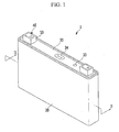
- FIG. 1 illustrates a perspective view of a rechargeable battery 1 according to a first embodiment of the invention
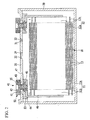
- FIG. 2 illustrates a cross-sectional view of the rechargeable battery 1 of FIG. 1 , taken along the line II-II.
- the rechargeable battery 1 includes an electrode assembly 10, a case 20, a cap plate 30, an electrode terminal 40, and an external insulator 50.
- the electrode assembly 10 is configured to charge and discharge current.
- the case 20 houses the electrode assembly 10.
- the cap plate 30 is coupled to an opening of the case 20.
- the electrode terminal 40 is provided in the cap plate 30.
- the external insulator 50 is configured to receive the electrode terminal 40 from an outside of the cap plate 30.
- the electrode assembly 10 is formed by disposing a negative electrode 11 and a positive electrode 12 at both sides of a separator 13 and spirally winding the negative electrode 11, the separator 13, and the positive electrode 12 in a jelly roll manner.
- the electrode assembly may be assembled by layering a negative electrode and a positive electrode formed of a single plate and interposing a separator therebetween, or may be assembled by folding and layering the negative electrode, the separator, and the positive electrode in a zigzag manner (not shown).
- the negative electrode 11 and the positive electrode 12 respectively include coated regions 11a and 12a where an active material is coated (not shown) on a current collector of each metal plate and uncoated regions 11b and 12b formed of current collectors exposed by not being coated by the active material.
- the uncoated region 11b of the negative electrode 11 is disposed at a first end of the negative electrode 11 along the spirally wound negative electrode 11.
- the uncoated region 12b of the positive electrode 12 is disposed at a first end of the positive electrode 12 along the spirally wound positive electrode 12. More particularly, the uncoated regions 11b and 12b are respectively disposed at both ends of the electrode assembly 10.
- the case 20 is formed in the shape of a cuboid.
- the case 20 includes a space for receiving the electrode assembly 10 and electrolyte solution.
- the case 20 includes an opening at one side of thereof, e.g., one side of the cuboid, to connect external and internal elements. The opening enables the electrode assembly 10 to be inserted into the case 20.
- the cap plate 30 is formed of a thin steel plate and is provided at the opening of the case 20.
- the cap plate 30 serves to close and seal the case 20.
- the cap plate 30 includes an electrolyte injection opening 31 and a vent hole 32. After the case 20 is coupled to the cap plate 30, electrolyte solution is injected into case 20 via the electrolyte injection opening 31. After injection of the electrolyte solution, the electrolyte injection opening 31 is sealed by a sealing cap 33.
- the vent hole 32 is closed and sealed by the vent plate 34.
- the vent hole 32 and vent plate 34 may enable release of an internal pressure of the rechargeable battery. More particularly, e.g., when the internal pressure of the rechargeable battery reaches a predetermined pressure level, the vent plate 34 may rupture and the vent hole 32 may be opened.
- the electrode terminal 40 includes a negative electrode terminal and a positive electrode terminal that penetrate the cap plate 30 and are electrically connected to the electrode assembly 10.
- the negative electrode terminal is electrically connected to the negative electrode 11 of the electrode assembly 10 and the positive electrode terminal is electrically connected to the positive electrode 12 of the electrode assembly 10.
- the electrode assembly 10 is drawn out to the outside of the case through the negative and positive electrode terminals, that is, the electrode terminals.
- the negative electrode terminal and the positive electrode terminal have the same structure, and therefore they will be described as the electrode terminal 40.
- the electrode terminal 40 includes a first plate terminal 41, a second plate terminal 42 separated from the first plate terminal 41, and a fuse portion 43 connecting the first plate terminal 41 and the second plate terminal 42 with each other.
- the electrode terminal 40 further includes a rivet terminal 44.
- the rivet terminal 44 connects the electrode assembly 10 and the first plate terminal 41 with each other.
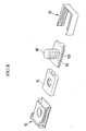
- FIG. 3 illustrates an exploded perspective view of the external insulator 50, the first plate terminal 41, and the second plate terminal 42
- FIGS. 4A , 4B , and 4C illustrate an assembly flowchart of the external insulator 50 and the first and second plate terminals 41, 42.
- the external insulator 50 may include a first insulator member 51 and a second insulator member 52.
- the first insulator member 51 and the second insulator member 52 partially receive the electrode terminal 40 and are coupled to each other to fix the electrode terminal 40 on the cap plate 30 in an electrically insulated manner.
- the first insulator member 51 separates and electrically insulates the first plate terminal 41 and the second plate terminal 42, and supports and surrounds parts of the first and second plate terminals 41 and 42.
- the second insulator member 52 is coupled to the first insulator member 51 and surrounds portions or sides of the first and second plate terminals 41 and 42, e.g., one or more portions or sides not surrounded by the first insulator member 51, for electric insulation and support. Portions of the first plate terminal 41 and the second plate terminal 42 are surrounded by one or both of the first insulator member 51 and/or the second insulator member 52.
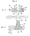
- FIG. 5 illustrates a cross sectional assembly diagram of the electrode terminal 40 in a sub-module state M1, M2 to the cap plate 30.
- the first insulator member 51 includes a first plate 511 disposed on the cap plate 30 and supporting the first plate terminal 41, a second plate 512 separated from the first plate 511 and supporting the second plate terminal 42, and a side wall 513 connecting side surfaces of the first and second plates 511, 512.
- the side wall 513 separates the first plate terminal 41 and the second plate terminal 42 from each other in a length direction of the rivet terminal 44, and surrounds side surfaces of the first and second plate terminals 41, 42.
- the first plate 511 includes a first through-hole H1.
- the first through-hole H1 corresponds to a through-hole 411 of the first plate terminal 41, and may enable riveting of the rivet terminal 44 to the through-hole 411 of the first plate terminal 41 by being penetrated therethrough.
- the second plate 512 includes a second through-hole H2.
- the second through-hole H2 corresponds to a through-hole 421 of the second plate terminal 42.
- the second through-hole H2 is at least partially aligned with the first through-hole H1 in an assembled state of the electrode terminal 40.
- the second through-hole H2 enables riveting with respect to the first through-hole H1.
- the second through-hole H2 and the through-hole 421 of the second plate terminal 42 enable treatment of a riveting tool.
- Diameters D2 of the second through-hole H2 of the second plate 512 and the through-hole 421 of the second plate terminal 42 are be larger than diameters D1 of the first through-hole H1 of the first plate 511 and the through-hole 411 of the first plate terminal 41 and, thus, insertion of a riveting tool may be eased.
- FIG. 3 illustrates the diameters D1 and D2 in the through-holes 411 and 421 of the first and second plate terminals 41 and 42.
- the side wall 513 includes a lower side wall 514 surrounding the first plate terminal 41 and an upper side wall 515 surrounding the second plate terminal 42.
- the lower side wall 514 surrounds side surfaces of the first plate terminal 41, e.g., the lower side wall 514 substantially and/or completely surrounds or overlaps three sides along three directions of the first plate terminal 41
- the upper side wall 515 surrounds side surfaces of the second plate terminal 42, e.g., the upper side wall 515 surrounds one side surface and a part of lateral side surfaces of the surface of the second plate terminal 42.
- the electrode terminal 40 includes a first sub-module M1 and a second sub-module M2.
- the first sub-module M1 may be arranged at a first side, e.g., external side, of the cap plate 30, and the second sub-module M2 may be arranged at a second side, e.g., inner side, of the cap plate 30.
- the first sub-module M1 includes the first and second plate terminal 41 and 42, the fuse portion 43, and the first and second insulator members 51 and 52.
- FIG. 6 illustrates a cross-sectional view of FIG. 4C , taken along the line VI-VI.
- the lower side wall 514 includes a coupling protrusion 521 formed in an opposite side wall of the second insulator member 52 and a lower coupling groove 516 slide-ably coupled with the coupling protrusion 521.
- the upper side wall 515 forms an upper coupling groove 517 slide-ably coupled to a coupling frame 422 of the second plate terminal 42.
- the second insulator member 52 includes a side wall 522 that may be connected to the side wall 513 of the first insulator member 51 and surrounds other side surfaces of the first and second plates 511 and 512 (see FIG. 3 ).
- the second insulator member 52 includes a snap 523 on an inner side of the side wall 522.
- the snap 523 couples with a snap groove 518 formed opposite thereto on the first insulator member 51 (see FIG. 3 ).
- the first plate terminal 41 and the second plate terminal 42 may be sequentially coupled to the first insulator member 51 and the second insulator member 52 may be coupled to the first insulator member 51 such that assembly of the first sub-module M1 shown in FIG. 5 and FIG. 6 may be completed.
- FIG. 7 illustrates a cross-sectional view of FIG. 4C , taken along the line VII-VII.
- the second insulator member 52 includes a slide groove 524 on the inner side of the side wall 522 that may be slide-ably coupled to the coupling frame 422 of the second plate terminal 42.
- the coupling frame 422 may be slide-ably coupled to the upper coupling groove 517 of the first insulator member 51 on one side, and slide-ably coupled to the slide groove 524 of the second insulator member 52 on another other side.
- the coupling frame 422 of the second plate terminal 42 may be coupled to the upper coupling groove 517 of the first insulator member 51 on one side, and simultaneously, may be coupled to the slide groove 524 of the second insulator member 52 on the other side.
- the fuse portion 43 has a width that is smaller than the width of the second plate terminal 42 and protrudes downward from the second plate terminal 42 such that the fuse portion 43 is electrically connected to a receiving groove 412 of the first plate terminal 41.
- the fuse portion 43 has high resistance compared to the first and second plate terminals 41 and 42, and corresponds to an electrically weak portion on charging and discharging lines.
- the fuse portion 43 is coupled to the receiving groove 412 of the first plate terminal 41 by welding.
- the fuse portion 43 is disposed in the inner side of the side wall 522 of the second insulator member 52 by being surrounded by the side wall 522.
- the fuse portion 43 is disposed outside of the space of the rechargeable battery, set by the case 20 and the cap plate 30, stability of the rechargeable battery can be maintained when arc is generated after the fuse is operated, and freedom for a design can be improved.
- the fuse portion 43 is supported by the first and second insulator members 51 and 52 coupled to each other, and is disposed in the first and second insulator members 51 and 52. Therefore, deterioration of the mechanical strength of the fuse portion 43 can be effectively prevented compared to the first and second plate terminals 41 and 42, and scattering of splinters due to the fuse operation can be prevented.
- the first and second plate terminals 41 and 42 are separated from each other and then connected through the fuse portion 43, and therefore the second plate terminal 42 can maintain flatness even though the rivet terminal 44 is riveted to the first plate terminal 41.
- a welding structure with the bus bar can be stably formed because the second plate terminal 42 maintains flatness.
- the electrode terminal 40 is provided in a terminal hole 35 of the cap plate 30 through the rivet terminal 44 including a gasket 47.
- the gasket 47 seals the external surface of the rivet terminal 44 and the inner surface of the terminal hole 35.
- the rivet terminal 44 is connected to a lead tab 46 through a flange 45 inside of the case 20, e.g., below the cap plate 30.
- the flange 45 is wider than the terminal hole 35 of the cap plate 30.
- the gasket 47 extends further between the flange 45 and an inner surface of the cap plate 30 to further seal the flange 45 and the cap plate 30. That is, the gasket 47 may prevent leakage of the electrolyte solution through the terminal hole 35 by which the electrode terminal 40 is provided on the cap plate 30.
- the lead tab 46 electrically connects the electrode terminal 40 to the negative and positive electrodes 11 and 12 of the electrode assembly 10. That is, the lead tab 46 is coupled to a lower end of the rivet terminal 44 and the lower end may be caulked such that the lead tab 46 is connected to the lower end of the rivet terminal 44 while being supported by the flange 45.
- An internal insulator 53 is provided between the lead tab 46 and the cap plate 30 for electrical insulation between the lead tab 46 and the cap plate 30.
- the internal insulator 53 is coupled to the cap plate 30 at one side and surrounds the lead tab 46 and the flange 45 and the rivet terminal 44 at another side for stabilization of the connection structure.
- the second sub-module M2 includes the lead tab 46, the internal insulator 53, the gasket 47, and the rivet terminal 44.
- the rivet terminal 44 is coupled with the lead tab 46, the internal insulator 53, and the gasket 47 such that the second sub-module M2 can be arranged on the inner side of the cap plate 30.
- an upper portion of the rivet terminal 44 is riveted to the first plate terminal 41 by inserting the second sub-module M2 in the terminal hole 35 in a lower portion of the cap plate 30 and arranging the first sub-module M1 on an upper portion of the cap plate 30 such that assembling of the cap plate 30 and the electrode terminal 40 can be improved.
- FIG. 8 illustrates an exploded perspective view of an external insulator 50 and an electrode terminal 240 of a rechargeable battery according to a second embodiment
- FIG. 9 illustrates an assembly cross-sectional view of FIG. 8
- the external insulator 50 includes a first insulator member 51 and a second insulator member 52 that are the same as those of the first embodiment.
- An electrode terminal 240 of the second embodiment includes the first plate terminal 41, the second plate terminal 42, the fuse portion 43, the rivet terminal 44, and a bolt 48. That is, the electrode terminal 240 of the second embodiment further includes the bolt 48 in addition of the electrode terminal 40 of the first embodiment.
- the bolt 48 is provided in a through-hole 421 of the second plate terminal 42 and externally protrudes from the second plate terminal 42.
- a head 481 of the bolt 48 is supported between the second plate terminal 42 and the first plate terminal 41 that are arranged facing each other.
- the second plate terminal 42 forms a receiving groove 482 receiving the head 481. More particularly, the head 481 is supported between the second plate terminal 42 and the first insulator member 51 and/or between the second plate terminal 42 and the second plate 512.
- a bus bar 54 can be installed by fastening a nut 49 to the bolt 48 while the bus bar 54 is provided in the second plate terminal 42 and the bolt 48.
- the bolt-nut fastening method of the second embodiment can further simplify installation of the bus bar 54.
Landscapes
- Chemical & Material Sciences (AREA)
- Chemical Kinetics & Catalysis (AREA)
- Electrochemistry (AREA)
- General Chemical & Material Sciences (AREA)
- Engineering & Computer Science (AREA)
- Manufacturing & Machinery (AREA)
- Inorganic Chemistry (AREA)
- Connection Of Batteries Or Terminals (AREA)
Claims (13)
- Wiederaufladbare Batterie, umfassend:eine Elektrodenanordnung (10), die so eingerichtet ist, dass sie Strom aufnimmt und abgibt;ein Gehäuse (20), in dem die Elektrodenanordnung eingebaut ist, wobei das Gehäuse eine Öffnung aufweist;eine Verschlussplatte (30), die mit der Öffnung des Gehäuses verbunden ist;einen Elektrodenanschluss (40), der auf der Verschlussplatte angeordnet ist; undeinen äußeren Isolator (50), der den Elektrodenanschluss von einer Außenseite der Verschlussplatte her aufnimmt,wobei der Elektrodenanschluss (40) Folgendes aufweist:einen ersten Plattenanschluss (41), der elektrisch mit der Elektrodenanordnung (10) verbunden ist,einen zweiten Plattenanschluss (42), der von dem ersten Plattenanschluss getrennt ist, undeinen Sicherungsabschnitt (43), der den ersten Plattenanschluss und den zweiten Plattenanschluss verbindet, dadurch gekennzeichnet, dassder äußere Isolator (50) Folgendes umfasst:ein erstes Isolatorelement (51), das so eingerichtet ist, dass es den ersten Plattenanschluss (41) und den zweiten Plattenanschluss (42) auf isolierte Weise hält und mindestens eine Seite des ersten und zweiten Plattenanschlusses umgibt, undein zweites Isolatorelement (52), das mit dem ersten Isolatorelement (51) verbunden ist,
wobei das erste Isolatorelement (51) Folgendes umfasst:eine erste Platte (511), die auf der Verschlussplatte (30) angeordnet und so eingerichtet ist, dass sie den ersten Plattenanschluss (41) hält;eine zweite Platte (512), die von der ersten Platte (511) getrennt und so eingerichtet ist, dass sie den zweiten Plattenanschluss (42) hält; undeine Seitenwand (513), die Seitenflächen der ersten und zweiten Platte (511, 512) verbindet und so mindestens eine Seite des ersten und zweiten Plattenanschlusses (41, 42) umgibt, wobei das zweite Isolierelement (52) die mindestens eine Seite des ersten und zweiten Plattenanschlusses (41, 42), die nicht von dem ersten Isolierelement (51) umgeben ist, umgibt. - Wiederaufladbare Batterie nach Anspruch 1, wobei die erste Platte (511) eine erste Durchgangsbohrung (H1) aufweist, die einer Durchgangsbohrung (411) des ersten Plattenanschlusses (41) entspricht, wobei die erste Durchgangsbohrung so eingerichtet ist, dass sie einen Nietanschluss (44) aufnimmt, und die zweite Platte (512) eine zweite Durchgangsbohrung (H2) aufweist, die einer Durchgangsbohrung (421) des zweiten Plattenanschlusses und der ersten Durchgangsbohrung entspricht.
- Wiederaufladbare Batterie nach Anspruch 1 oder 2, wobei die Seitenwand (513) des ersten Isolatorelements (51) eine untere Seitenwand (514) aufweist, die den ersten Plattenanschluss (41) umgibt, und eine obere Seitenwand (515), die den zweiten Plattenanschluss (42) umgibt.
- Wiederaufladbare Batterie nach Anspruch 3, wobei die untere Seitenwand (514) eine untere Verbindungsnut (516) aufweist, die verschiebbar mit einem Verbindungsvorsprung (521) einer Seitenwand des zweiten Isolatorelements (52), der gegenüber der unteren Verbindungsnut angeordnet ist, verbunden ist.
- Wiederaufladbare Batterie nach Anspruch 3 oder 4, wobei die obere Seitenwand (515) eine obere Verbindungsnut (517) aufweist, die verschiebbar mit einem Verbindungsrahmen (422) des zweiten Plattenanschlusses (42), der gegenüber der oberen Verbindungsnut (517) angeordnet ist, verbunden ist.
- Wiederaufladbare Batterie nach einem der vorhergehenden Ansprüche, wobei das zweite Isolatorelement (52) eine Seitenwand (522) aufweist, die mit der Seitenwand (513) des ersten Isolatorelements (51) verbunden ist und so die mindestens eine andere Seitenfläche der ersten und zweiten Platte umgibt.
- Wiederaufladbare Batterie nach Anspruch 6, wobei das zweite Isolatorelement (52) eine Rastvorrichtung (523) an einer Innenseite der Seitenwand (522) aufweist, damit sie mit einer Rastnut (518) des ersten Isolatorelements (51), die gegenüber der Rastvorrichtung (523) angeordnet ist, verbunden ist.
- Wiederaufladbare Batterie nach Anspruch 6 oder 7, wobei das zweite Isolatorelement (52) eine Einschubnut (524) an einer Innenseite der Seitenwand (522) aufweist, damit sie verschiebbar mit einem Verbindungsrahmen (422) des zweiten Plattenanschlusses, der gegenüber der Einschubnut (524) angeordnet ist, verbunden ist.
- Wiederaufladbare Batterie nach Anspruch 6 oder 7 oder 8, wobei der Sicherungsabschnitt (43) von dem zweiten Plattenanschluss (42) aus nach unten ragt und der Sicherungsabschnitt (43) eine Breite aufweist, die kleiner ist als eine Breite des zweiten Plattenanschlusses (42), und elektrisch mit einer Aufnahmenut (412) des ersten Plattenanschlusses (41) verbunden ist.
- Wiederaufladbare Batterie nach einem vorhergehenden Anspruch, wobei der Elektrodenanschluss (40) ferner eine Schraube (48) aufweist, die in einer Durchgangsbohrung (421) des zweiten Plattenanschlusses (42) angeordnet ist.
- Wiederaufladbare Batterie nach Anspruch 10, wobei ein Kopf (481) der Schraube (48) zwischen dem zweiten Plattenanschluss (42) und der zweiten Platte (512), die einander gegenüberliegen, gehalten ist.
- Wiederaufladbare Batterie nach Anspruch 10, wobei ein Kopf (481) der Schraube (48) zwischen dem zweiten Plattenanschluss (42) und dem ersten Plattenanschluss (41) gehalten ist.
- Wiederaufladbare Batterie nach Anspruch 10, wobei ein Kopf (481) der Schraube (48) zwischen dem zweiten Plattenanschluss (42) und dem ersten Isolatorelement (51) gehalten ist.
Applications Claiming Priority (1)
| Application Number | Priority Date | Filing Date | Title |
|---|---|---|---|
| KR1020110101286A KR101711978B1 (ko) | 2011-10-05 | 2011-10-05 | 이차 전지 |
Publications (2)
| Publication Number | Publication Date |
|---|---|
| EP2579357A1 EP2579357A1 (de) | 2013-04-10 |
| EP2579357B1 true EP2579357B1 (de) | 2014-10-22 |
Family
ID=46603690
Family Applications (1)
| Application Number | Title | Priority Date | Filing Date |
|---|---|---|---|
| EP12178554.7A Active EP2579357B1 (de) | 2011-10-05 | 2012-07-30 | Wiederaufladbare Batterie |
Country Status (3)
| Country | Link |
|---|---|
| US (1) | US9287549B2 (de) |
| EP (1) | EP2579357B1 (de) |
| KR (1) | KR101711978B1 (de) |
Cited By (1)
| Publication number | Priority date | Publication date | Assignee | Title |
|---|---|---|---|---|
| EP3544086B1 (de) * | 2018-03-20 | 2025-10-15 | Samsung SDI Co., Ltd. | Batteriepack |
Families Citing this family (19)
| Publication number | Priority date | Publication date | Assignee | Title |
|---|---|---|---|---|
| KR101243546B1 (ko) * | 2011-03-02 | 2013-03-20 | 로베르트 보쉬 게엠베하 | 이차 전지 및 이를 갖는 배터리 팩 |
| US9023498B2 (en) * | 2011-07-07 | 2015-05-05 | Samsung Sdi Co., Ltd. | Rechargeable battery |
| KR101696010B1 (ko) * | 2013-06-19 | 2017-01-12 | 삼성에스디아이 주식회사 | 이차 전지 |
| US10333113B2 (en) | 2013-06-19 | 2019-06-25 | Samsung Sdi Co., Ltd. | Rechargeable battery having retainer |
| KR101744087B1 (ko) * | 2013-06-25 | 2017-06-07 | 삼성에스디아이 주식회사 | 이차 전지 |
| KR101720619B1 (ko) * | 2013-10-08 | 2017-03-28 | 삼성에스디아이 주식회사 | 이차전지 |
| KR102248595B1 (ko) | 2014-04-15 | 2021-05-06 | 삼성에스디아이 주식회사 | 이차 전지 |
| KR20150136412A (ko) * | 2014-05-27 | 2015-12-07 | 삼성에스디아이 주식회사 | 플레이트 터미널을 갖는 이차 전지 |
| KR102306443B1 (ko) | 2014-09-26 | 2021-09-28 | 삼성에스디아이 주식회사 | 이차 전지 |
| KR102263199B1 (ko) * | 2014-11-12 | 2021-06-10 | 삼성에스디아이 주식회사 | 이차 전지 |
| KR102360013B1 (ko) * | 2015-04-21 | 2022-02-07 | 삼성에스디아이 주식회사 | 이차 전지 |
| KR102606264B1 (ko) * | 2016-06-28 | 2023-11-23 | 삼성에스디아이 주식회사 | 이차전지 |
| KR102632924B1 (ko) * | 2018-09-19 | 2024-02-02 | 삼성에스디아이 주식회사 | 이차 전지 |
| US10971714B2 (en) * | 2019-03-15 | 2021-04-06 | GM Global Technology Operations LLC | Battery pack and a pre-assembled electrical connection unit for the battery pack |
| CN209747563U (zh) | 2019-05-27 | 2019-12-06 | 宁德时代新能源科技股份有限公司 | 顶盖组件以及二次电池 |
| CN113302785B (zh) * | 2020-04-30 | 2022-05-10 | 宁德时代新能源科技股份有限公司 | 端盖组件、二次电池、电池组以及用电装置 |
| DE102020118843A1 (de) | 2020-07-16 | 2022-01-20 | Bayerische Motoren Werke Aktiengesellschaft | Batteriezelle mit einer elektrischen Sicherung |
| CN217788568U (zh) * | 2022-05-18 | 2022-11-11 | 宁德时代新能源科技股份有限公司 | 端盖组件、电池单体、电池及用电设备 |
| KR102785413B1 (ko) * | 2025-01-10 | 2025-03-25 | 케이이엠텍 주식회사 | 이차 전지의 캡 어셈블리 |
Family Cites Families (17)
| Publication number | Priority date | Publication date | Assignee | Title |
|---|---|---|---|---|
| US5348815A (en) * | 1993-06-10 | 1994-09-20 | Black & Decker Inc. | Protective battery cap |
| JPH08315802A (ja) | 1995-05-16 | 1996-11-29 | Sony Corp | ヒューズ内蔵端子および電池または電源機器 |
| JPH09153352A (ja) | 1995-11-30 | 1997-06-10 | Canon Inc | 電子機器の電池パック |
| JP3929839B2 (ja) * | 2001-06-28 | 2007-06-13 | 松下電器産業株式会社 | 電池及び電池パック |
| US20040170887A1 (en) * | 2001-08-07 | 2004-09-02 | Kenjin Masumoto | Non-aqueous electrolytic secondary battery |
| CN100508248C (zh) * | 2002-05-27 | 2009-07-01 | 株式会社杰士汤浅 | 电池 |
| US6902434B2 (en) | 2002-07-23 | 2005-06-07 | Cooper Technologies Company | Battery fuse bus bar assembly |
| JP4191469B2 (ja) | 2002-12-18 | 2008-12-03 | パナソニック株式会社 | 角形電池 |
| JP2008159351A (ja) | 2006-12-22 | 2008-07-10 | Matsushita Electric Ind Co Ltd | 電池装置 |
| KR100855583B1 (ko) | 2007-07-03 | 2008-09-01 | 넥스콘 테크놀러지 주식회사 | 휴대용 단말기의 배터리팩 및 그 제조방법 |
| KR101030858B1 (ko) * | 2007-09-28 | 2011-04-22 | 삼성에스디아이 주식회사 | 이차전지 |
| JP2010146735A (ja) | 2008-12-16 | 2010-07-01 | Toyota Motor Corp | 密閉型電池 |
| KR101042808B1 (ko) * | 2010-01-26 | 2011-06-20 | 에스비리모티브 주식회사 | 이차 전지 |
| EP2360754B1 (de) | 2010-01-26 | 2013-11-13 | Samsung SDI Co., Ltd. | Batterieanordnung |
| JP5501018B2 (ja) | 2010-02-15 | 2014-05-21 | 矢崎総業株式会社 | バッテリに直付けされるヒュージブルリンクの斜め締め防止保護キャップ |
| US8309246B2 (en) * | 2010-10-25 | 2012-11-13 | Sb Limotive Co., Ltd. | Terminal of rechargeable battery and method of manufacturing the same |
| JP5699578B2 (ja) * | 2010-12-10 | 2015-04-15 | 株式会社Gsユアサ | 電池 |
-
2011
- 2011-10-05 KR KR1020110101286A patent/KR101711978B1/ko active Active
-
2012
- 2012-05-31 US US13/484,687 patent/US9287549B2/en active Active
- 2012-07-30 EP EP12178554.7A patent/EP2579357B1/de active Active
Cited By (1)
| Publication number | Priority date | Publication date | Assignee | Title |
|---|---|---|---|---|
| EP3544086B1 (de) * | 2018-03-20 | 2025-10-15 | Samsung SDI Co., Ltd. | Batteriepack |
Also Published As
| Publication number | Publication date |
|---|---|
| KR101711978B1 (ko) | 2017-03-06 |
| EP2579357A1 (de) | 2013-04-10 |
| KR20130036989A (ko) | 2013-04-15 |
| US9287549B2 (en) | 2016-03-15 |
| US20130089760A1 (en) | 2013-04-11 |
Similar Documents
| Publication | Publication Date | Title |
|---|---|---|
| EP2579357B1 (de) | Wiederaufladbare Batterie | |
| EP3166158B1 (de) | Wiederaufladbares batteriemodul | |
| US9023498B2 (en) | Rechargeable battery | |
| EP2624327B1 (de) | Wiederaufladbare Batterie | |
| US9508978B2 (en) | Rechargeable battery module | |
| EP2395576B1 (de) | Wiederaufladbare Batterie mit Sicherung | |
| EP2461393B1 (de) | Wiederaufladbare Batterie | |
| US8435659B2 (en) | Rechargeable battery | |
| EP2903056A1 (de) | Rechteckige sekundärbatterie | |
| EP2768069B1 (de) | Batteriemodul | |
| EP2866281B1 (de) | Wiederaufladbare Batterie mit Sicherungseinheit | |
| EP2733770A1 (de) | Wiederaufladbares Batteriemodul | |
| EP2445033B1 (de) | Wiederaufladbare Batterie | |
| KR20150099193A (ko) | 이차 전지 모듈 | |
| JP5297441B2 (ja) | 二次電池 | |
| KR100599793B1 (ko) | 이차 전지와 이에 사용되는 전극 조립체 | |
| US20130089759A1 (en) | Rechargeable battery | |
| CN105914304B (zh) | 可再充电电池及其模块 | |
| US9246143B2 (en) | Rechargeable battery module | |
| CN109075304B (zh) | 具有隔膜的可再充电电池 | |
| KR20080049547A (ko) | 원통형 이차전지 | |
| KR101121205B1 (ko) | 이차전지 | |
| EP2775554B1 (de) | Wiederaufladbare Batterie |
Legal Events
| Date | Code | Title | Description |
|---|---|---|---|
| PUAI | Public reference made under article 153(3) epc to a published international application that has entered the european phase |
Free format text: ORIGINAL CODE: 0009012 |
|
| AK | Designated contracting states |
Kind code of ref document: A1 Designated state(s): AL AT BE BG CH CY CZ DE DK EE ES FI FR GB GR HR HU IE IS IT LI LT LU LV MC MK MT NL NO PL PT RO RS SE SI SK SM TR |
|
| AX | Request for extension of the european patent |
Extension state: BA ME |
|
| 17P | Request for examination filed |
Effective date: 20130503 |
|
| GRAP | Despatch of communication of intention to grant a patent |
Free format text: ORIGINAL CODE: EPIDOSNIGR1 |
|
| INTG | Intention to grant announced |
Effective date: 20140514 |
|
| GRAS | Grant fee paid |
Free format text: ORIGINAL CODE: EPIDOSNIGR3 |
|
| GRAA | (expected) grant |
Free format text: ORIGINAL CODE: 0009210 |
|
| AK | Designated contracting states |
Kind code of ref document: B1 Designated state(s): AL AT BE BG CH CY CZ DE DK EE ES FI FR GB GR HR HU IE IS IT LI LT LU LV MC MK MT NL NO PL PT RO RS SE SI SK SM TR |
|
| REG | Reference to a national code |
Ref country code: GB Ref legal event code: FG4D |
|
| REG | Reference to a national code |
Ref country code: CH Ref legal event code: EP |
|
| REG | Reference to a national code |
Ref country code: AT Ref legal event code: REF Ref document number: 692996 Country of ref document: AT Kind code of ref document: T Effective date: 20141115 |
|
| REG | Reference to a national code |
Ref country code: IE Ref legal event code: FG4D |
|
| REG | Reference to a national code |
Ref country code: DE Ref legal event code: R096 Ref document number: 602012003476 Country of ref document: DE Effective date: 20141204 |
|
| REG | Reference to a national code |
Ref country code: NL Ref legal event code: VDEP Effective date: 20141022 |
|
| REG | Reference to a national code |
Ref country code: AT Ref legal event code: MK05 Ref document number: 692996 Country of ref document: AT Kind code of ref document: T Effective date: 20141022 |
|
| REG | Reference to a national code |
Ref country code: LT Ref legal event code: MG4D |
|
| PG25 | Lapsed in a contracting state [announced via postgrant information from national office to epo] |
Ref country code: NO Free format text: LAPSE BECAUSE OF FAILURE TO SUBMIT A TRANSLATION OF THE DESCRIPTION OR TO PAY THE FEE WITHIN THE PRESCRIBED TIME-LIMIT Effective date: 20150122 Ref country code: FI Free format text: LAPSE BECAUSE OF FAILURE TO SUBMIT A TRANSLATION OF THE DESCRIPTION OR TO PAY THE FEE WITHIN THE PRESCRIBED TIME-LIMIT Effective date: 20141022 Ref country code: ES Free format text: LAPSE BECAUSE OF FAILURE TO SUBMIT A TRANSLATION OF THE DESCRIPTION OR TO PAY THE FEE WITHIN THE PRESCRIBED TIME-LIMIT Effective date: 20141022 Ref country code: PT Free format text: LAPSE BECAUSE OF FAILURE TO SUBMIT A TRANSLATION OF THE DESCRIPTION OR TO PAY THE FEE WITHIN THE PRESCRIBED TIME-LIMIT Effective date: 20150223 Ref country code: NL Free format text: LAPSE BECAUSE OF FAILURE TO SUBMIT A TRANSLATION OF THE DESCRIPTION OR TO PAY THE FEE WITHIN THE PRESCRIBED TIME-LIMIT Effective date: 20141022 Ref country code: LT Free format text: LAPSE BECAUSE OF FAILURE TO SUBMIT A TRANSLATION OF THE DESCRIPTION OR TO PAY THE FEE WITHIN THE PRESCRIBED TIME-LIMIT Effective date: 20141022 Ref country code: IS Free format text: LAPSE BECAUSE OF FAILURE TO SUBMIT A TRANSLATION OF THE DESCRIPTION OR TO PAY THE FEE WITHIN THE PRESCRIBED TIME-LIMIT Effective date: 20150222 |
|
| PG25 | Lapsed in a contracting state [announced via postgrant information from national office to epo] |
Ref country code: RS Free format text: LAPSE BECAUSE OF FAILURE TO SUBMIT A TRANSLATION OF THE DESCRIPTION OR TO PAY THE FEE WITHIN THE PRESCRIBED TIME-LIMIT Effective date: 20141022 Ref country code: PL Free format text: LAPSE BECAUSE OF FAILURE TO SUBMIT A TRANSLATION OF THE DESCRIPTION OR TO PAY THE FEE WITHIN THE PRESCRIBED TIME-LIMIT Effective date: 20141022 Ref country code: HR Free format text: LAPSE BECAUSE OF FAILURE TO SUBMIT A TRANSLATION OF THE DESCRIPTION OR TO PAY THE FEE WITHIN THE PRESCRIBED TIME-LIMIT Effective date: 20141022 Ref country code: SE Free format text: LAPSE BECAUSE OF FAILURE TO SUBMIT A TRANSLATION OF THE DESCRIPTION OR TO PAY THE FEE WITHIN THE PRESCRIBED TIME-LIMIT Effective date: 20141022 Ref country code: LV Free format text: LAPSE BECAUSE OF FAILURE TO SUBMIT A TRANSLATION OF THE DESCRIPTION OR TO PAY THE FEE WITHIN THE PRESCRIBED TIME-LIMIT Effective date: 20141022 Ref country code: CY Free format text: LAPSE BECAUSE OF FAILURE TO SUBMIT A TRANSLATION OF THE DESCRIPTION OR TO PAY THE FEE WITHIN THE PRESCRIBED TIME-LIMIT Effective date: 20141022 Ref country code: AT Free format text: LAPSE BECAUSE OF FAILURE TO SUBMIT A TRANSLATION OF THE DESCRIPTION OR TO PAY THE FEE WITHIN THE PRESCRIBED TIME-LIMIT Effective date: 20141022 Ref country code: GR Free format text: LAPSE BECAUSE OF FAILURE TO SUBMIT A TRANSLATION OF THE DESCRIPTION OR TO PAY THE FEE WITHIN THE PRESCRIBED TIME-LIMIT Effective date: 20150123 |
|
| REG | Reference to a national code |
Ref country code: DE Ref legal event code: R097 Ref document number: 602012003476 Country of ref document: DE |
|
| PG25 | Lapsed in a contracting state [announced via postgrant information from national office to epo] |
Ref country code: EE Free format text: LAPSE BECAUSE OF FAILURE TO SUBMIT A TRANSLATION OF THE DESCRIPTION OR TO PAY THE FEE WITHIN THE PRESCRIBED TIME-LIMIT Effective date: 20141022 Ref country code: RO Free format text: LAPSE BECAUSE OF FAILURE TO SUBMIT A TRANSLATION OF THE DESCRIPTION OR TO PAY THE FEE WITHIN THE PRESCRIBED TIME-LIMIT Effective date: 20141022 Ref country code: DK Free format text: LAPSE BECAUSE OF FAILURE TO SUBMIT A TRANSLATION OF THE DESCRIPTION OR TO PAY THE FEE WITHIN THE PRESCRIBED TIME-LIMIT Effective date: 20141022 Ref country code: CZ Free format text: LAPSE BECAUSE OF FAILURE TO SUBMIT A TRANSLATION OF THE DESCRIPTION OR TO PAY THE FEE WITHIN THE PRESCRIBED TIME-LIMIT Effective date: 20141022 Ref country code: SK Free format text: LAPSE BECAUSE OF FAILURE TO SUBMIT A TRANSLATION OF THE DESCRIPTION OR TO PAY THE FEE WITHIN THE PRESCRIBED TIME-LIMIT Effective date: 20141022 |
|
| PLBE | No opposition filed within time limit |
Free format text: ORIGINAL CODE: 0009261 |
|
| STAA | Information on the status of an ep patent application or granted ep patent |
Free format text: STATUS: NO OPPOSITION FILED WITHIN TIME LIMIT |
|
| PG25 | Lapsed in a contracting state [announced via postgrant information from national office to epo] |
Ref country code: IT Free format text: LAPSE BECAUSE OF FAILURE TO SUBMIT A TRANSLATION OF THE DESCRIPTION OR TO PAY THE FEE WITHIN THE PRESCRIBED TIME-LIMIT Effective date: 20141022 |
|
| 26N | No opposition filed |
Effective date: 20150723 |
|
| PG25 | Lapsed in a contracting state [announced via postgrant information from national office to epo] |
Ref country code: SI Free format text: LAPSE BECAUSE OF FAILURE TO SUBMIT A TRANSLATION OF THE DESCRIPTION OR TO PAY THE FEE WITHIN THE PRESCRIBED TIME-LIMIT Effective date: 20141022 Ref country code: MC Free format text: LAPSE BECAUSE OF FAILURE TO SUBMIT A TRANSLATION OF THE DESCRIPTION OR TO PAY THE FEE WITHIN THE PRESCRIBED TIME-LIMIT Effective date: 20141022 |
|
| REG | Reference to a national code |
Ref country code: CH Ref legal event code: PL |
|
| PG25 | Lapsed in a contracting state [announced via postgrant information from national office to epo] |
Ref country code: LU Free format text: LAPSE BECAUSE OF FAILURE TO SUBMIT A TRANSLATION OF THE DESCRIPTION OR TO PAY THE FEE WITHIN THE PRESCRIBED TIME-LIMIT Effective date: 20150730 |
|
| REG | Reference to a national code |
Ref country code: IE Ref legal event code: MM4A |
|
| PG25 | Lapsed in a contracting state [announced via postgrant information from national office to epo] |
Ref country code: LI Free format text: LAPSE BECAUSE OF NON-PAYMENT OF DUE FEES Effective date: 20150731 Ref country code: CH Free format text: LAPSE BECAUSE OF NON-PAYMENT OF DUE FEES Effective date: 20150731 |
|
| REG | Reference to a national code |
Ref country code: FR Ref legal event code: PLFP Year of fee payment: 5 |
|
| PG25 | Lapsed in a contracting state [announced via postgrant information from national office to epo] |
Ref country code: IE Free format text: LAPSE BECAUSE OF NON-PAYMENT OF DUE FEES Effective date: 20150730 |
|
| PG25 | Lapsed in a contracting state [announced via postgrant information from national office to epo] |
Ref country code: MT Free format text: LAPSE BECAUSE OF FAILURE TO SUBMIT A TRANSLATION OF THE DESCRIPTION OR TO PAY THE FEE WITHIN THE PRESCRIBED TIME-LIMIT Effective date: 20141022 |
|
| PG25 | Lapsed in a contracting state [announced via postgrant information from national office to epo] |
Ref country code: HU Free format text: LAPSE BECAUSE OF FAILURE TO SUBMIT A TRANSLATION OF THE DESCRIPTION OR TO PAY THE FEE WITHIN THE PRESCRIBED TIME-LIMIT; INVALID AB INITIO Effective date: 20120730 Ref country code: BG Free format text: LAPSE BECAUSE OF FAILURE TO SUBMIT A TRANSLATION OF THE DESCRIPTION OR TO PAY THE FEE WITHIN THE PRESCRIBED TIME-LIMIT Effective date: 20141022 Ref country code: SM Free format text: LAPSE BECAUSE OF FAILURE TO SUBMIT A TRANSLATION OF THE DESCRIPTION OR TO PAY THE FEE WITHIN THE PRESCRIBED TIME-LIMIT Effective date: 20141022 |
|
| REG | Reference to a national code |
Ref country code: FR Ref legal event code: PLFP Year of fee payment: 6 |
|
| PG25 | Lapsed in a contracting state [announced via postgrant information from national office to epo] |
Ref country code: TR Free format text: LAPSE BECAUSE OF FAILURE TO SUBMIT A TRANSLATION OF THE DESCRIPTION OR TO PAY THE FEE WITHIN THE PRESCRIBED TIME-LIMIT Effective date: 20141022 |
|
| PG25 | Lapsed in a contracting state [announced via postgrant information from national office to epo] |
Ref country code: BE Free format text: LAPSE BECAUSE OF FAILURE TO SUBMIT A TRANSLATION OF THE DESCRIPTION OR TO PAY THE FEE WITHIN THE PRESCRIBED TIME-LIMIT Effective date: 20141022 |
|
| PG25 | Lapsed in a contracting state [announced via postgrant information from national office to epo] |
Ref country code: MK Free format text: LAPSE BECAUSE OF FAILURE TO SUBMIT A TRANSLATION OF THE DESCRIPTION OR TO PAY THE FEE WITHIN THE PRESCRIBED TIME-LIMIT Effective date: 20141022 |
|
| REG | Reference to a national code |
Ref country code: FR Ref legal event code: PLFP Year of fee payment: 7 |
|
| PG25 | Lapsed in a contracting state [announced via postgrant information from national office to epo] |
Ref country code: AL Free format text: LAPSE BECAUSE OF FAILURE TO SUBMIT A TRANSLATION OF THE DESCRIPTION OR TO PAY THE FEE WITHIN THE PRESCRIBED TIME-LIMIT Effective date: 20141022 |
|
| REG | Reference to a national code |
Ref country code: DE Ref legal event code: R079 Ref document number: 602012003476 Country of ref document: DE Free format text: PREVIOUS MAIN CLASS: H01M0002300000 Ipc: H01M0050543000 |
|
| P01 | Opt-out of the competence of the unified patent court (upc) registered |
Effective date: 20230530 |
|
| PGFP | Annual fee paid to national office [announced via postgrant information from national office to epo] |
Ref country code: GB Payment date: 20250626 Year of fee payment: 14 |
|
| PGFP | Annual fee paid to national office [announced via postgrant information from national office to epo] |
Ref country code: FR Payment date: 20250623 Year of fee payment: 14 |
|
| PGFP | Annual fee paid to national office [announced via postgrant information from national office to epo] |
Ref country code: DE Payment date: 20250624 Year of fee payment: 14 |