EP2574510A2 - Handbremshebel für Kraftfahrzeuge - Google Patents
Handbremshebel für Kraftfahrzeuge Download PDFInfo
- Publication number
- EP2574510A2 EP2574510A2 EP12006580A EP12006580A EP2574510A2 EP 2574510 A2 EP2574510 A2 EP 2574510A2 EP 12006580 A EP12006580 A EP 12006580A EP 12006580 A EP12006580 A EP 12006580A EP 2574510 A2 EP2574510 A2 EP 2574510A2
- Authority
- EP
- European Patent Office
- Prior art keywords
- hand brake
- brake lever
- lever
- push rod
- damping element
- Prior art date
- Legal status (The legal status is an assumption and is not a legal conclusion. Google has not performed a legal analysis and makes no representation as to the accuracy of the status listed.)
- Granted
Links
- 238000013016 damping Methods 0.000 claims abstract description 27
- 239000000463 material Substances 0.000 claims abstract description 9
- 230000006835 compression Effects 0.000 claims description 25
- 238000007906 compression Methods 0.000 claims description 25
- 239000006260 foam Substances 0.000 claims description 4
- 239000006261 foam material Substances 0.000 abstract 1
- 238000005253 cladding Methods 0.000 description 12
- 239000002184 metal Substances 0.000 description 4
- 238000009434 installation Methods 0.000 description 3
- 239000002344 surface layer Substances 0.000 description 3
- 229920002943 EPDM rubber Polymers 0.000 description 2
- 239000004952 Polyamide Substances 0.000 description 2
- 239000004743 Polypropylene Substances 0.000 description 2
- 238000004512 die casting Methods 0.000 description 2
- 239000010985 leather Substances 0.000 description 2
- 238000004519 manufacturing process Methods 0.000 description 2
- 238000000034 method Methods 0.000 description 2
- 239000004033 plastic Substances 0.000 description 2
- 229920003023 plastic Polymers 0.000 description 2
- 229920002647 polyamide Polymers 0.000 description 2
- 229920001155 polypropylene Polymers 0.000 description 2
- 238000003860 storage Methods 0.000 description 2
- 229920003051 synthetic elastomer Polymers 0.000 description 2
- 239000005061 synthetic rubber Substances 0.000 description 2
- 229920002725 thermoplastic elastomer Polymers 0.000 description 2
- 241000446313 Lamella Species 0.000 description 1
- -1 Polypropylene Polymers 0.000 description 1
- 239000004676 acrylonitrile butadiene styrene Substances 0.000 description 1
- 238000004026 adhesive bonding Methods 0.000 description 1
- 239000011248 coating agent Substances 0.000 description 1
- 238000000576 coating method Methods 0.000 description 1
- 238000011161 development Methods 0.000 description 1
- 230000018109 developmental process Effects 0.000 description 1
- 238000010438 heat treatment Methods 0.000 description 1
- 238000001746 injection moulding Methods 0.000 description 1
- 230000003287 optical effect Effects 0.000 description 1
- 239000004800 polyvinyl chloride Substances 0.000 description 1
- 239000006228 supernatant Substances 0.000 description 1
- 239000012815 thermoplastic material Substances 0.000 description 1
Images


Classifications
-
- B—PERFORMING OPERATIONS; TRANSPORTING
- B60—VEHICLES IN GENERAL
- B60T—VEHICLE BRAKE CONTROL SYSTEMS OR PARTS THEREOF; BRAKE CONTROL SYSTEMS OR PARTS THEREOF, IN GENERAL; ARRANGEMENT OF BRAKING ELEMENTS ON VEHICLES IN GENERAL; PORTABLE DEVICES FOR PREVENTING UNWANTED MOVEMENT OF VEHICLES; VEHICLE MODIFICATIONS TO FACILITATE COOLING OF BRAKES
- B60T7/00—Brake-action initiating means
- B60T7/02—Brake-action initiating means for personal initiation
- B60T7/08—Brake-action initiating means for personal initiation hand actuated
- B60T7/10—Disposition of hand control
- B60T7/102—Disposition of hand control by means of a tilting lever
- B60T7/104—Disposition of hand control by means of a tilting lever with a locking mechanism
- B60T7/105—Disposition of hand control by means of a tilting lever with a locking mechanism the lock being released by means of a push button
-
- G—PHYSICS
- G05—CONTROLLING; REGULATING
- G05G—CONTROL DEVICES OR SYSTEMS INSOFAR AS CHARACTERISED BY MECHANICAL FEATURES ONLY
- G05G1/00—Controlling members, e.g. knobs or handles; Assemblies or arrangements thereof; Indicating position of controlling members
- G05G1/04—Controlling members for hand actuation by pivoting movement, e.g. levers
- G05G1/06—Details of their grip parts
Definitions
- the invention relates to a handbrake lever for motor vehicles with a handle portion, a connected to the handle portion, sleeve-shaped cover and extending in the longitudinal direction of the handle portion and against the force of a compression spring axially displaceable push rod with end disposed actuating button, wherein the panel is a radially aligned and in Has supporting direction of the push rod extending support.
- Such a hand brake lever as an actuating device for a parking brake, such as is used in motor vehicles, is already out of the DE 10 2007 053 461 A1 known.
- the hand brake lever is pivotally mounted in a fixedly connected to the vehicle body bearing block.
- the handbrake lever is composed of a front lever portion in the form of a handle portion, a central lever portion for receiving a locking device and a rear lever portion with a Glasstofffact for a traction means, such as a linkage and / or a cable together.
- the handbrake lever is made of cast metal, preferably light metal according to a known die casting process.
- the handle part is designed as a closed hollow profile.
- the push rod which end has an actuating button, mounted longitudinally movable against the force of a compression spring.
- the handle part is enclosed on the outside by a sleeve-shaped panel and firmly connected thereto. To accommodate the operating knob, the panel on the front of an opening.
- the panel or the operating knob For radial support of the operating knob on the panel, the panel or the operating knob on radially oriented and extending in the direction of the push rod supporting elements.
- the support members are formed as punctiform projections and disposed between an outer surface of the actuating knob and an outer surface facing the inner surface of the panel.
- Such an embodiment of the handbrake lever requires an increased installation effort, which is caused in particular by the additional components in the form of the sockets for supporting the compression spring in the closed hollow profile of the handle part.
- the DE 20 2009 013 243 U1 , the EP 1 818 229 A1 and the EP 1 818 230 A1 also describe hand brake devices for motor vehicles with counter to the force of a spring longitudinally displaceable push rods.
- the invention has the object to provide an improved hand brake lever available, which also requires less installation effort.
- a handbrake lever for motor vehicles in which the support element is arranged in the longitudinal direction between the actuating button and the handle part and an actuating button facing away from the end portion of the compression spring is supported on the support element.
- the assembly and manufacturing effort is also reduced by the fact that the panel and the support element are integrally formed.
- the panel and the support consist mainly of plastic and can be manufactured for example by injection molding.
- thermoplastic materials such as acrylonitrile-butadiene-styrene (ABS), polyvinyl chloride (PVC), Polypropylene (PP) or polyamide (PA) into consideration.
- two-component embodiments are possible, wherein in an outer region for haptic and / or optical reasons thermoplastic elastomers (TPE) or a synthetic rubber (EPDM) is provided.
- TPE thermoplastic elastomers
- EPDM synthetic rubber
- an additional surface layer for example made of leather, or an additional coating of a suitable material can be applied.
- the support element extends over the entire circumference of the cladding. Due to the annular and circumferential configuration of the support a stable abutment for the particular designed as a helical spring compression spring is provided, wherein the outer turn of the compression spring rests fully on the support element.
- the cladding comprises two or more circumferentially distributed support elements, which are arranged in a common, aligned transversely to the longitudinal direction of the handle portion plane.
- the support elements are then arranged uniformly over the circumference of the panel.
- the panel and the handle part are permanently connected to each other.
- a relative movement between the handle part and the panel is prevented and ensures that the support element is located at a defined distance to the push rod or the actuating button, so that the spring functionally and reliably between the operating knob and the support element can be arranged and supported.
- the connection between the cladding and the handle part can be done by material connection, by adhesion or by positive engagement, with an interference fit between the cladding and the handle part has proven to be particularly advantageous in terms of installation effort.
- the operating knob is detachably connected to the push rod. This results in a further simplification of the assembly, since the actuating button, after the compression spring has been arranged on the push rod and has come into abutment in the panel on the support element, is attached to the end of the push rod.
- the actuating knob is mounted in the front portion of the panel in this and also serves as an abutment for the compression spring.
- the push rod Before mounting the panel on the handle part, the push rod is first arranged in the hand brake lever or in the handle part. Subsequently, the cladding is heated depending on the material used to a temperature of about 60-80 ° C in order to reduce the assembly forces when sliding the sleeve-shaped cladding on the handle part. Heating the cladding minimizes the risk of visible deformation in the cladding when it is pushed on. In a fully assembled panel, the push rod is a bit out of the cladding. This projection is detected during the sliding of the panel on the handle part by a laterally arranged measuring system and compared with a target value. The sliding of the panel is continued until the supernatant corresponds to the desired value.
- the panel and the handle part can be compensated.
- the compression spring is pushed over the push rod until the compression spring comes to rest on the support element of the panel.
- the operation knob is placed on the free end of the push rod so that the compression spring is supported between the support member and the operation knob.
- the panel has a damping element on which a pressure spring facing surface of the actuating button is supported in an engaged end position.
- the damping element consists of an elastically deformable material, in particular a foam, and is fixed to the panel or the support element.
- the damping element may be made of a soft synthetic rubber (eg EPDM) and fixed by material connection, for example by gluing, or by positive locking, for example by latching, or by adhesion to the panel or the supporting element. It has proved particularly expedient that the damping element is pressed into a recess formed in the cladding or in the supporting element, designed as a hollow. The fixing of the damping element is then carried out before the operating knob is finally locked on the push rod.
- EPDM soft synthetic rubber
- the damping element and the panel may also be integrally formed.
- the damping element is molded into this as part of the manufacturing process of the panel.
- the damping element in the one-piece embodiment consists of the same material as the cladding, it is provided that the damping element has a plurality of grooves and / or lamellae. Due to the groove and / or lamellar contour, a sufficient noise reduction can be ensured.
- the slats or grooves can also be arranged discontinuously distributed on the surface of the damping element.
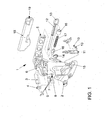
- FIG. 1 shows a conventional actuator for a parking brake, such as is used in motor vehicles.
- said actuating device comprises a hand brake lever 1, which in turn is pivotally mounted in a fixedly connected to the vehicle body bearing block 2 by means of known storage parts in the form of an axis 3 and a bearing bushing 4.
- the handbrake lever 1 is made in one piece of cast metal, preferably light metal, or of a suitable plastic according to a known die casting process.
- the hand brake lever 1 is composed of a front lever portion in the form of a handle portion 5, a central lever portion 6 for receiving a locking device and a rear lever portion 7 with a Switzerlandstofffact 8 for a suitable traction means 9, which may be a linkage and / or a cable together ,
- the locking device consists essentially of a means of rivets 10 fixedly connected to the bearing block 2 toothed segment 11, in which a by means of a push rod 12 operatively engageable and actuated by means of a rivet 14 and actuated by means of a rivet 14, pivotable pawl 15 engages positively to fix the handbrake lever 1 by means of a push rod 12.
- the handle portion 5 of the parking brake lever 1 is formed as a cross-sectionally substantially closed hollow profile with lateral, window-like recesses or with oppositely arranged pockets and webs.
- the push rod 12 is supported by means of separate sockets 16 and guided longitudinally displaceable in the axial direction. Furthermore, the push rod 12 is spring-loaded in a manner known per se, in this case by means of a compression spring 17, which is supported with one end portion on one of the bushes 16 and with the other end portion on the push rod 12 and the actuating knob 13.
- Such a configuration, in particular of the handle part 5 of the handbrake lever 1 is accompanied by an increased assembly costs, which in particular the additional components in Form of the sockets 16 for supporting the compression spring 17 is owed in the largely closed hollow profile of the handle part 5.
- a surrounding the handle portion 5 panel 18 is provided in the front region of the handbrake lever 1, wherein the panel 18 has an opening 19 for receiving the actuating knob 13.
- FIGS. 2 to 4 show a inventively designed handbrake lever 1 in different views.
- push rod 12 of the actuating knob 13 is releasably, for example, by a latching connection, fixed.
- the support element 20 is formed integrally with the panel 18 and arranged in the longitudinal direction between the actuating knob 13 and the handle portion 5 and a the actuating head 13 facing end face 21 of the handle portion 5.
- the compression spring 17 is supported with a front region on the actuating knob 13 and with a rear end portion 22 facing away from the actuating knob 13 on the support element 20.
- the handbrake lever 1 or the cover 18 has a damping element 23, on which a pressure spring 17 facing surface of the actuating knob 13 is supported in an engaged end position.
- a recess 24 formed as a recess is provided in the lining 18 or in the support element 20.
- FIG. 5 shows a second embodiment of the handbrake lever 1 according to the invention in a partially sectioned side view.
- a surface layer 26 for example made of leather, fixed by means of a latching connection 25.
- FIGS. 6 and 7 show a view according to arrow I from FIG. 3 without actuating button 13 and without or with damping element 23.
- the damping element 23 is in the recess. 24 pressed in the panel 18 and in the support member 20.
- FIG. 8 A third embodiment of the handbrake lever according to the invention is in FIG. 8 represented and the FIGS. 9 to 11 show different embodiments of the detail II FIG. 8 in an enlarged view.
- the damping element 23 is in all Embodiments fixed to the panel 18, for example glued, and arranged such that a projection 27 of the actuating knob 13, the damping element 23 contacted in an engaged end position.
- the damping element 23 may be formed as a foam ring 28 ( FIG. 9 ) and / or a plurality of circumferentially spaced grooves 29 (FIG. FIG. 10 ) or slats 30 (FIG. FIG. 11 ) exhibit.
Landscapes
- Engineering & Computer Science (AREA)
- Transportation (AREA)
- Mechanical Engineering (AREA)
- Braking Elements And Transmission Devices (AREA)
- Mechanical Control Devices (AREA)
- Steering Devices For Bicycles And Motorcycles (AREA)
Abstract
Description
- Die Erfindung betrifft einen Handbremshebel für Kraftfahrzeuge mit einem Griffteil, einer mit dem Griffteil verbundenen, hülsenförmigen Verkleidung und einer sich in Längsrichtung des Griffteils erstreckenden und gegen die Kraft einer Druckfeder axial verschiebbaren Druckstange mit endseitig angeordnetem Betätigungsknopf, wobei die Verkleidung ein radial ausgerichtetes und sich in Richtung der Druckstange erstreckendes Abstützelement aufweist.
- Ein derartiger Handbremshebel als Betätigungsvorrichtung für eine Feststellbremse, wie sie in Kraftfahrzeugen Verwendung findet, ist bereits aus der
DE 10 2007 053 461 A1 bekannt. Der Handbremshebel ist schwenkbeweglich in einem mit der Kraftfahrzeugkarosserie fest verbundenen Lagerbock gelagert. Der Handbremshebel setzt sich aus einem vorderen Hebelabschnitt in Form eines Griffteils, einem mittleren Hebelabschnitt zur Aufnahme einer Arretiereinrichtung und einem hinteren Hebelabschnitt mit einer Zugmittelaufnahme für ein Zugmittel, beispielsweise ein Gestänge und/oder einen Seilzug, zusammen. Der Handbremshebel ist aus Metallguss, vorzugsweise Leichtmetall nach einem bekannten Druckgussverfahren hergestellt. - Das Griffteil ist als geschlossenes Hohlprofil ausgebildet. Innerhalb des Hohlprofils ist die Druckstange, welche endseitig einen Betätigungsknopf aufweist, entgegen der Kraft einer Druckfeder längsbeweglich gelagert. Für die Abstützung der Feder sind Buchsen vorgesehen. Weiterhin ist das Griffteil außenseitig von einer hülsenförmigen Verkleidung umschlossen und fest mit dieser verbunden. Zur Aufnahme des Betätigungsknopfs weist die Verkleidung im vorderen Bereich eine Öffnung auf.
- Zur radialen Abstützung des Betätigungsknopfs an der Verkleidung weist die Verkleidung oder der Betätigungsknopf radial ausgerichtete und sich in Richtung der Druckstange erstreckende Abstützelemente auf. Die Abstützelemente sind als punktförmig ausgebildete Fortsätze ausgebildet und zwischen einer äußeren Oberfläche des Betätigungsknopfs und einer dieser äußeren Oberfläche zugewandten inneren Oberfläche der Verkleidung angeordnet.
- Eine derartige Ausgestaltung des Handbremshebels erfordert einen erhöhten Montageaufwand, welcher insbesondere durch die zusätzlichen Bauteile in Form der Buchsen zur Abstützung der Druckfeder im geschlossenen Hohlprofil des Griffteils verursacht wird.
- Die
DE 20 2009 013 243 U1 , dieEP 1 818 229 A1 und dieEP 1 818 230 A1 beschreiben ebenfalls Handbremseinrichtungen für Kraftfahrzeuge mit entgegen der Kraft einer Feder längsverschiebbaren Druckstangen. - Vor diesem Hintergrund liegt der Erfindung die Aufgabe zugrunde, einen verbesserten Handbremshebel zur Verfügung zu stellen, welcher auch einen geringeren Montageaufwand erfordert.
- Diese Aufgabe wird gelöst mit einem Handbremshebel gemäß den Merkmalen des Patentanspruchs 1. Die Unteransprüche betreffen besonders zweckmäßige Weiterbildungen der Erfindung.
- Erfindungsgemäß ist also ein Handbremshebel für Kraftfahrzeuge vorgesehen, bei welchem das Abstützelement in Längsrichtung zwischen dem Betätigungsknopf und dem Griffteil angeordnet ist und sich ein dem Betätigungsknopf abgewandter Endabschnitt der Druckfeder an dem Abstützelement abstützt. Aus einer derartigen Ausgestaltung des Handbremshebels resultiert ein geringerer Montageaufwand, da zusätzliche Bauteile in Form von Buchsen zur Abstützung der Druckfeder nicht erforderlich sind. Das Widerlager für die Druckfeder ist in der Verkleidung integriert. Die Lagerung der Druckfeder erfolgt also zwischen der Verkleidung und dem Betätigungsknopf. Zusätzlich zu montierende Bauteile für die Abstützung der Druckfeder sind nicht erforderlich. Im Vergleich zum eingangs genannten Stand der Technik weist der Handbremshebel außerdem eine geringere Länge auf, um Platz für die Anordnung der Druckfeder im vorderen Bereich des Handbremshebels zu schaffen. Auf eine Fettung der Druckfeder, wie sie in herkömmlichen Handbremshebeln erforderlich ist, kann verzichtet werden, da die Druckfeder durch den kurzen Bauraum stabiler ausgeführt ist und einen größeren Abstand zur Druckstange aufweist.
- Der Montage- und Herstellungsaufwand wird auch dadurch reduziert, dass die Verkleidung und das Abstützelement einstückig ausgebildet sind. Die Verkleidung und das Abstützelement bestehen vorwiegend aus Kunststoff und können beispielsweise im Spritzgussverfahren hergestellt werden. Als Material für die Verkleidung kommen insbesondere thermoplastische Kunststoffe, wie beispielsweise Acrylnitril-Butadien-Styrol (ABS), Polyvinylchlorid (PVC), Polypropylen (PP) oder Polyamid (PA) in Betracht. Auch zweikomponentige Ausgestaltungen sind möglich, wobei in einem äußeren Bereich aus haptischen und/oder optischen Gründen thermoplastische Elastomere (TPE) oder ein synthetischer Kautschuk (EPDM) vorgesehen ist. Selbstverständlich kann auf einer äußeren Oberfläche der Verkleidung, je nach Ausstattungsvariante des Kraftfahrzeugs, auch eine zusätzliche Oberflächenschicht, beispielsweise aus Leder, oder eine zusätzliche Beschichtung aus einem geeigneten Material aufgebracht werden.
- Dabei erweist es sich als besonders vorteilhaft, dass sich das Abstützelement über den gesamten Umfang der Verkleidung erstreckt. Durch die ringförmige und umlaufende Ausgestaltung des Abstützelements wird ein stabiles Widerlager für die insbesondere als Schraubenfeder ausgebildete Druckfeder zur Verfügung gestellt, wobei die äußere Windung der Druckfeder vollumfänglich an dem Abstützelement anliegt.
- Eine alternative Ausführungsform der vorliegenden Erfindung wird auch dadurch erreicht, dass die Verkleidung zwei oder mehrere über den Umfang verteilte Abstützelemente aufweist, welche in einer gemeinsamen, quer zur Längsrichtung des Griffteils ausgerichteten Ebene angeordnet sind. In vorteilhafter Weise sind die Abstützelemente dann gleichmäßig über den Umfang der Verkleidung angeordnet.
- Erfindungsgemäß ist weiter vorgesehen, dass die Verkleidung und das Griffteil unlösbar miteinander verbunden sind. Hierdurch wird eine Relativbewegung zwischen dem Griffteil und der Verkleidung verhindert und gewährleistet, dass sich das Abstützelement in einem definierten Abstand zur Druckstange bzw. zum Betätigungsknopf befindet, sodass die Feder funktions- und prozesssicher zwischen dem Betätigungsknopf und dem Abstützelement angeordnet werden und sich abstützen kann. Die Verbindung zwischen Verkleidung und Griffteil kann durch Stoffschluss, durch Kraftschluss oder durch Formschluss erfolgen, wobei sich eine Presspassung zwischen der Verkleidung und dem Griffteil insbesondere hinsichtlich des Montageaufwands als besonders vorteilhaft erwiesen hat.
- Außerdem erweist es sich als besonders zweckmäßig, dass der Betätigungsknopf lösbar mit der Druckstange verbunden ist. Hierdurch ergibt sich eine weitere Vereinfachung der Montage, da der Betätigungsknopf, nachdem die Druckfeder auf der Druckstange angeordnet wurde und in der Verkleidung an dem Abstützelement zur Anlage gekommen ist, endseitig auf die Druckstange aufgesteckt wird. Der Betätigungsknopf ist in dem vorderen Abschnitt der Verkleidung in dieser gelagert und dient auch als Widerlager für die Druckfeder.
- Vor der Montage der Verkleidung auf dem Griffteil wird zunächst die Druckstange in dem Handbremshebel bzw. in dem Griffteil angeordnet. Anschließend wird die Verkleidung je nach verwendetem Material auf eine Temperatur von ca. 60-80 °C erwärmt, um die Montagekräfte beim Aufschieben der hülsenförmig ausgebildeten Verkleidung auf das Griffteil zu reduzieren. Durch die Erwärmung der Verkleidung wird die Gefahr, dass bei dem Aufschieben sichtbare Verformungen in der Verkleidung entstehen, minimiert. Bei einer fertig montierten Verkleidung steht die Druckstange ein Stück aus der Verkleidung heraus. Dieser Überstand wird während des Aufschiebens der Verkleidung auf das Griffteil durch ein seitlich angeordnetes Messsystem erfasst und mit einem Sollwert verglichen. Das Aufschieben der Verkleidung wird so lange fortgesetzt, bis der Überstand dem Sollwert entspricht. Durch eine derartige Montage können Bauteiltoleranzen der Druckstange, der Verkleidung und des Griffteils kompensiert werden. Anschließend wird die Druckfeder über die Druckstange geschoben, bis die Druckfeder an dem Abstützelement der Verkleidung zur Anlage kommt. Dann wird der Betätigungsknopf auf dem freien Ende der Druckstange angeordnet, sodass sich die Druckfeder zwischen dem Abstützelement und dem Betätigungsknopf abstützt.
- Ein weiteres erfindungsgemäßes Merkmal besteht darin, dass die Verkleidung ein Dämpfungselement aufweist, an welchem sich eine der Druckfeder zugewandte Fläche des Betätigungsknopfs in einer eingerückten Endlage abstützt. Hierdurch kann die Geräuschentwicklung beim Entriegeln der Handbremse reduziert werden, da das Dämpfungselement einen unmittelbaren Kontakt des Betätigungsknopfs mit der Verkleidung, durch welchen das Geräusch erzeugt wird, verhindert.
- In diesem Fall erweist es sich als vorteilhaft, dass das Dämpfungselement aus einem elastisch verformbaren Material, insbesondere einem Schaumstoff, besteht und an der Verkleidung oder dem Abstützelement fixiert ist. Das Dämpfungselement kann aus einem weichen synthetischen Kautschuk (z. B. EPDM) bestehen und durch Stoffschluss, beispielsweise durch Kleben, oder durch Formschluss, beispielsweise durch Verrasten, oder durch Kraftschluss an der Verkleidung oder dem Abstützelement fixiert werden. Als besonders zweckmäßig hat es sich erwiesen, dass das Dämpfungselement in eine in der Verkleidung oder im Abstützelement integrierte, als Mulde ausgebildete Ausnehmung gepresst wird. Die Fixierung des Dämpfungselements erfolgt dann, bevor der Betätigungsknopf abschließend auf der Druckstange verrastet wird.
- Alternativ können das Dämpfungselement und die Verkleidung auch einstückig ausgebildet sein. Hierbei wird das Dämpfungselement im Rahmen des Herstellungsprozesses der Verkleidung an diese angespritzt.
- Da das Dämpfungselement in der einstückigen Ausgestaltung aus dem gleichen Material wie die Verkleidung besteht, ist vorgesehen, dass das Dämpfungselement mehrere Rillen und/oder Lamellen aufweist. Durch die Rillen- und/oder Lamellenkontur kann eine ausreichende Geräuschreduzierung gewährleistet werden. Hierbei können zwischen 4 und 12 Rillen bzw. Lamellen gleichmäßig verteilt auf der Fläche des Dämpfungselements angeordnet werden. Insbesondere bei Packageproblemen können die Lamellen bzw. Rillen jedoch auch unstetig verteilt auf der Fläche des Dämpfungselements angeordnet werden.
- Die Erfindung lässt zahlreiche Ausführungsformen zu. Zur weiteren Verdeutlichung ihres Grundprinzips ist eine davon in der Zeichnung dargestellt und wird nachfolgend beschrieben. Diese zeigt in
- Fig. 1
- eine Explosionsdarstellung einer Betätigungsvorrichtung für eine Feststellbremse nach dem Stand der Technik;
- Fig. 2
- einen erfindungsgemäß ausgebildeten Handbremshebel in einer teilweise geschnittenen Seitenansicht;
- Fig. 3
- den vorderen Bereich des in
Figur 2 dargestellten Handbremshebels in einer vergrößerten Darstellung; - Fig. 4
- den in
Figur 3 dargestellten Handbremshebel in einer perspektivischen Ansicht; - Fig. 5
- eine zweite Ausführungsform des erfindungsgemäßen Handbremshebels in einer teilweise geschnittenen Seitenansicht;
- Fig. 6
- eine Ansicht gemäß Pfeil I aus
Figur 3 ohne Betätigungsknopf und ohne Dämpfungselement; - Fig. 7
- eine Ansicht gemäß Pfeil I aus
Figur 3 ohne Betätigungsknopf und mit Dämpfungselement; - Fig. 8
- eine dritte Ausführungsform des erfindungsgemäßen Handbremshebels in einer teilweise geschnittenen Seitenansicht;
- Fig. 9-11
- Einzelheit II aus
Figur 8 in verschiedenen Ausführungsvarianten. -
Figur 1 zeigt eine herkömmliche Betätigungsvorrichtung für eine Feststellbremse, wie sie in Kraftfahrzeugen Verwendung findet. Im Wesentlichen umfasst die besagte Betätigungsvorrichtung einen Handbremshebel 1, der seinerseits in einem mit der Kraftfahrzeugkarosserie fest verbundenen Lagerbock 2 mittels an sich bekannter Lagerungsteile in Form einer Achse 3 und einer Lagerbuchse 4 schwenkgelagert ist. - Der Handbremshebel 1 ist einteilig aus Metallguss, vorzugsweise Leichtmetall, oder aus einem geeigneten Kunststoff nach einem an sich bekannten Druckgussverfahren hergestellt.
- Der Handbremshebel 1 setzt sich aus einem vorderen Hebelabschnitt in Form eines Griffteils 5, einem mittleren Hebelabschnitt 6 zur Aufnahme einer Arretiereinrichtung und einem hinteren Hebelabschnitt 7 mit einer Zugmittelaufnahme 8 für ein geeignetes Zugmittel 9, welches ein Gestänge und/oder ein Seilzug sein kann, zusammen.
- Die Arretiereinrichtung besteht im Wesentlichen aus einem mittels Nieten 10 fest mit dem Lagerbock 2 verbundenen Zahnsegment 11, in welches eine mittels einer Druckstange 12 mit Betätigungsknopf 13 wirkverbindbare und betätigbare und mittels eines Nietes 14 fixierte, schwenkbare Sperrklinke 15 zur Festsetzung des Handbremshebels 1 formschlüssig eingreift.
- Wie
Figur 1 weiter zu entnehmen ist, ist das Griffteil 5 des Handbremshebels 1 als im Querschnitt im Wesentlichen geschlossenes Hohlprofil mit seitlichen, fensterähnlichen Ausnehmungen bzw. mit gegenüberliegend angeordneten Taschen und Stegen ausgebildet. - Innerhalb des Hohlprofils ist die Druckstange 12 mittels separater Buchsen 16 abgestützt und in axialer Richtung längsverschieblich geführt. Weiterhin ist die Druckstange 12 in an sich bekannter Art und Weise federkraftbeaufschlagt, vorliegend mittels einer Druckfeder 17, die sich mit einem Endabschnitt an einer der Buchsen 16 und mit dem anderen Endabschnitt an der Druckstange 12 bzw. dem Betätigungsknopf 13 abstützt.
- Eine derartige Ausgestaltung insbesondere des Griffteils 5 des Handbremshebels 1 geht mit einem erhöhten Montageaufwand einher, welcher insbesondere den zusätzlichen Bauteilen in Form der Buchsen 16 zur Abstützung der Druckfeder 17 im weitestgehend geschlossenen Hohlprofil des Griffteils 5 geschuldet ist.
- Weiterhin ist eine das Griffteil 5 umgebende Verkleidung 18 im vorderen Bereich des Handbremshebels 1 vorgesehen, wobei die Verkleidung 18 eine Öffnung 19 zur Aufnahme des Betätigungsknopfs 13 aufweist.
- Die
Figuren 2 bis 4 zeigen einen erfindungsgemäß ausgebildeten Handbremshebel 1 in unterschiedlichen Ansichten. Die mittels einer Presspassung fest mit dem Griffteil 5 verbundene hülsenförmige Verkleidung 18 weist ein radial ausgerichtetes und sich in Richtung der Druckstange 12 erstreckendes Abstützelement 20 auf. An dem freien Ende der in dem Hohlprofil des Griffteils 5 angeordneten Druckstange 12 ist der Betätigungsknopf 13 lösbar, beispielsweise durch eine Rastverbindung, fixiert. Das Abstützelement 20 ist einstückig mit der Verkleidung 18 ausgebildet und in Längsrichtung zwischen dem Betätigungsknopf 13 und dem Griffteil 5 bzw. einer dem Betätigungskopf 13 zugewandten Stirnfläche 21 des Griffteils 5 angeordnet. Die Druckfeder 17 stützt sich mit einem vorderen Bereich an dem Betätigungsknopf 13 und mit einem dem Betätigungsknopf 13 abgewandten hinteren Endabschnitt 22 an dem Abstützelement 20 ab. - Weiterhin weist der Handbremshebel 1 bzw. die Verkleidung 18 ein Dämpfungselement 23 auf, an welchem sich eine der Druckfeder 17 zugewandte Fläche des Betätigungsknopfs 13 in einer eingerückten Endlage abstützt. Für die Aufnahme des Dämpfungselements 23 ist in der Verkleidung 18 bzw. in dem Abstützelement 20 eine als Mulde ausgebildete Ausnehmung 24 vorgesehen.
-
Figur 5 zeigt eine zweite Ausführungsform des erfindungsgemäßen Handbremshebels 1 in einer teilweise geschnittenen Seitenansicht. Auf der Verkleidung 18 ist mittels einer Rastverbindung 25 eine Oberflächenschicht 26, beispielsweise aus Leder, fixiert. - Die
Figuren 6 und 7 zeigen eine Ansicht gemäß Pfeil I ausFigur 3 ohne Betätigungsknopf 13 und ohne bzw. mit Dämpfungselement 23. Das Dämpfungselement 23 ist in die Ausnehmung . 24 in der Verkleidung 18 bzw. in dem Abstützelement 20 eingepresst. - Eine dritte Ausführungsform des erfindungsgemäßen Handbremshebels ist in
Figur 8 dargestellt und dieFiguren 9 bis 11 zeigen verschiedene Ausführungsvarianten der Einzelheit II ausFigur 8 in einer vergrößerten Darstellung. Das Dämpfungselement 23 ist in allen Ausführungsvarianten an der Verkleidung 18 fixiert, beispielsweise verklebt, und derart angeordnet, dass ein Vorsprung 27 des Betätigungsknopfs 13 das Dämpfungselement 23 in einer eingerückten Endlage kontaktiert. Dabei kann das Dämpfungselement 23 als Schaumstoffring 28 ausgebildet sein (Figur 9 ) und/oder mehrere über den Umfang verteilt angeordnete Rillen 29 (Figur 10 ) oder Lamellen 30 (Figur 11 ) aufweisen. -
- 1
- Handbremshebel
- 2
- Lagerbock
- 3
- Achse
- 4
- Lagerbuchse
- 5
- Griffteil
- 6
- mittlerer Hebelabschnitt
- 7
- hinterer Hebelabschnitt
- 8
- Zugmittelaufnahme
- 9
- Zugmittel
- 10
- Niet
- 11
- Zahnsegment
- 12
- Druckstange
- 13
- Betätigungsknopf
- 14
- Niet
- 15
- Sperrklinke
- 16
- Buchsen
- 17
- Druckfeder
- 18
- Verkleidung
- 19
- Öffnung
- 20
- Abstützelement
- 21
- Stirnftäche
- 22
- Endabschnitt
- 23
- Dämpfungselement
- 24
- Ausnehmung
- 25
- Rastverbindung
- 26
- Oberflächenschicht
- 27
- Vorsprung
- 28
- Schaumstoffring
- 29
- Rille
- 30
- Lamelle
Claims (10)
- Handbremshebel (1) für Kraftfahrzeuge mit einem Griffteil (5), einer mit dem Griffteil (5) verbundenen, hülsenförmigen Verkleidung (18) und einer sich in Längsrichtung des Griffteils (5) erstreckenden und gegen die Kraft einer Druckfeder (17) axial verschiebbaren Druckstange (12) mit endseitig angeordnetem Betätigungsknopf (13), wobei die Verkleidung (18) ein radial ausgerichtetes und sich in Richtung der Druckstange (12) erstreckendes Abstützelement (20) aufweist, dadurch gekennzeichnet, dass das Abstützelement (20) in Längsrichtung zwischen dem Betätigungsknopf (13) und dem Griffteil (5) angeordnet ist und dass sich ein dem Betätigungsknopf (13) abgewandter Endabschnitt (22) der Druckfeder (17) an dem Abstützelement (20) abstützt.
- Handbremshebel (1) nach Anspruch 1, dadurch gekennzeichnet, dass die Verkleidung (18) und das Abstützelement (20) einstückig ausgebildet sind.
- Handbremshebel (1) nach den Ansprüchen 1 oder 2, dadurch gekennzeichnet, dass sich das Abstützelement (20) über den gesamten Umfang der Verkleidung (18) erstreckt.
- Handbremshebel (1) nach zumindest einem der vorangehenden Ansprüche, dadurch gekennzeichnet, dass die Verkleidung (18) zwei oder mehrere über den Umfang verteilte Abstützelemente (20) aufweist, welche in einer gemeinsamen, quer zur Längsrichtung des Griffteils (5) ausgerichteten Ebene angeordnet sind.
- Handbremshebel (1) nach zumindest einem der vorangehenden Ansprüche, dadurch gekennzeichnet, dass die Verkleidung (18) und das Griffteil (5) unlösbar miteinander verbunden sind.
- Handbremshebel (1) nach zumindest einem der vorangehenden Ansprüche, dadurch gekennzeichnet, dass der Betätigungsknopf (13) lösbar mit der Druckstange (12) verbunden ist.
- Handbremshebel (1) nach zumindest einem der vorangehenden Ansprüche, dadurch gekennzeichnet, dass die Verkleidung (18) ein Dämpfungselement (23) aufweist, an welchem sich eine der Druckfeder (17) zugewandte Fläche des Betätigungsknopfs (13) in einer eingerückten Endlage abstützt.
- Handbremshebel (1) nach zumindest einem der vorangehenden Ansprüche, dadurch gekennzeichnet, dass das Dämpfungselement (23) aus einem elastisch verformbaren Material, insbesondere einem Schaumstoff, besteht und an der Verkleidung (18) oder dem Abstützelement (20) fixiert ist.
- Handbremshebel (1) nach zumindest einem der vorangehenden Ansprüche, dadurch gekennzeichnet, dass das Dämpfungselement (23) und die Verkleidung (18) einstückig ausgebildet sind.
- Handbremshebel (1) nach zumindest einem der vorangehenden Ansprüche, dadurch gekennzeichnet, dass das Dämpfungselement (23) mehrere Rillen (29) und/oder Lamellen (30) aufweist.
Applications Claiming Priority (1)
| Application Number | Priority Date | Filing Date | Title |
|---|---|---|---|
| DE102011114592A DE102011114592A1 (de) | 2011-09-30 | 2011-09-30 | Handbremshebel für Kraftfahrzeuge |
Publications (3)
| Publication Number | Publication Date |
|---|---|
| EP2574510A2 true EP2574510A2 (de) | 2013-04-03 |
| EP2574510A3 EP2574510A3 (de) | 2017-01-18 |
| EP2574510B1 EP2574510B1 (de) | 2018-08-15 |
Family
ID=47008221
Family Applications (1)
| Application Number | Title | Priority Date | Filing Date |
|---|---|---|---|
| EP12006580.0A Active EP2574510B1 (de) | 2011-09-30 | 2012-09-19 | Handbremshebel für Kraftfahrzeuge |
Country Status (4)
| Country | Link |
|---|---|
| EP (1) | EP2574510B1 (de) |
| CN (1) | CN103085786B (de) |
| DE (1) | DE102011114592A1 (de) |
| ES (1) | ES2697053T3 (de) |
Families Citing this family (1)
| Publication number | Priority date | Publication date | Assignee | Title |
|---|---|---|---|---|
| DE102019205361A1 (de) * | 2019-04-12 | 2020-10-15 | Lisi Automotive Kkp Gmbh & Co. Kg | Montageklammer, Feststellbremse und Kraftfahrzeug |
Citations (4)
| Publication number | Priority date | Publication date | Assignee | Title |
|---|---|---|---|---|
| EP1818229A1 (de) | 2006-02-09 | 2007-08-15 | DGS Druckguss Systeme AG | Handbremseinrichtung |
| EP1818230A1 (de) | 2006-02-09 | 2007-08-15 | DGS Druckguss Systeme AG | Handbremseinrichtung |
| DE102007053461A1 (de) | 2007-11-09 | 2009-05-14 | Volkswagen Ag | Handbremshebel für Kraftfahrzeuge |
| DE202009013243U1 (de) | 2009-10-02 | 2009-12-10 | Dietz-Automotive Gmbh & Co. Kg | Betätigungsvorrichtung für eine Feststellbremse |
Family Cites Families (10)
| Publication number | Priority date | Publication date | Assignee | Title |
|---|---|---|---|---|
| GB859611A (en) * | 1958-07-30 | 1961-01-25 | Sackville Ltd | Improvements relating to hand brake levers for road vehicles |
| GB1118431A (en) * | 1963-12-13 | 1968-07-03 | Sackville Ltd | Hand-brake lever assemblies for motor vehicles |
| JPS592653B2 (ja) * | 1977-01-25 | 1984-01-19 | トヨタ自動車株式会社 | パ−キングブレ−キ操作装置 |
| DE3727625C1 (en) * | 1987-08-19 | 1989-01-26 | Opel Adam Ag | Handbrake lever for a parking brake |
| JP2527612B2 (ja) * | 1989-04-14 | 1996-08-28 | 三菱自動車工業株式会社 | パ―キングブレ―キ用操作装置 |
| KR20000001471A (ko) * | 1998-06-11 | 2000-01-15 | 김태구 | 자동차의 핸드브레이크 |
| DE19847523C2 (de) * | 1998-10-15 | 2003-01-09 | Kendrion Rsl Gmbh & Co Kg | Handbremshebel |
| CN2376406Y (zh) * | 1999-04-19 | 2000-05-03 | 国营江西省金溪县汽车配件厂 | 一种手制动操纵杆总成 |
| JP3839285B2 (ja) * | 2001-08-31 | 2006-11-01 | 本田技研工業株式会社 | パーキングブレーキ装置 |
| US20100242666A1 (en) * | 2006-02-02 | 2010-09-30 | Yeon-Soo Kim | Anti-loosening device for parking brake |
-
2011
- 2011-09-30 DE DE102011114592A patent/DE102011114592A1/de active Pending
-
2012
- 2012-09-19 ES ES12006580T patent/ES2697053T3/es active Active
- 2012-09-19 EP EP12006580.0A patent/EP2574510B1/de active Active
- 2012-10-08 CN CN201210596832.5A patent/CN103085786B/zh active Active
Patent Citations (4)
| Publication number | Priority date | Publication date | Assignee | Title |
|---|---|---|---|---|
| EP1818229A1 (de) | 2006-02-09 | 2007-08-15 | DGS Druckguss Systeme AG | Handbremseinrichtung |
| EP1818230A1 (de) | 2006-02-09 | 2007-08-15 | DGS Druckguss Systeme AG | Handbremseinrichtung |
| DE102007053461A1 (de) | 2007-11-09 | 2009-05-14 | Volkswagen Ag | Handbremshebel für Kraftfahrzeuge |
| DE202009013243U1 (de) | 2009-10-02 | 2009-12-10 | Dietz-Automotive Gmbh & Co. Kg | Betätigungsvorrichtung für eine Feststellbremse |
Also Published As
| Publication number | Publication date |
|---|---|
| ES2697053T3 (es) | 2019-01-21 |
| CN103085786B (zh) | 2016-02-17 |
| EP2574510B1 (de) | 2018-08-15 |
| EP2574510A3 (de) | 2017-01-18 |
| DE102011114592A1 (de) | 2013-04-04 |
| CN103085786A (zh) | 2013-05-08 |
Similar Documents
| Publication | Publication Date | Title |
|---|---|---|
| EP2896539B1 (de) | System zur Pedalkraftsimulation, insbesondere für ein Kupplungsbetätigungssystem | |
| EP1912824B1 (de) | Fahrzeug-haltegriff | |
| EP3585671B1 (de) | Lager für eine lenkspindel und lenksäule für ein kraftfahrzeug | |
| EP3509920B1 (de) | Bremsgerät für eine hydraulische kraftfahrzeugbremsanlage | |
| DE202005021617U1 (de) | Biegefeste Kolbenzylindereinheit | |
| DE102007061640C5 (de) | Kugelgelenkverbinder | |
| DE102007008724B4 (de) | Scheibenbremse, insbesondere für ein Nutzfahrzeug | |
| DE102015010054A1 (de) | Hydraulikzylinder, insbesondere Nehmerzylinder für eine hydraulische Kupplungsbetätigung für Kraftfahrzeuge | |
| EP2574510B1 (de) | Handbremshebel für Kraftfahrzeuge | |
| WO2017182430A1 (de) | Dichtungsvorrichtung | |
| DE102018123007A1 (de) | Lenkrad für ein kraftfahrzeug | |
| EP2520479A2 (de) | Geber für ein hydraulisches Betätigungselement | |
| DE102015010055A1 (de) | Hydraulikzylinder, insbesondere Nehmerzylinder für eine hydraulische Kupplungsbetätigung für Kraftfahrzeuge | |
| DE102009022460B4 (de) | Betätigungsvorrichtung für eine Feststellbremse | |
| DE10134601B4 (de) | Kopfstützenhülse für eine Führungsstange einer Kopfstütze | |
| DE202016105991U1 (de) | Federstütze | |
| DE102013216919B3 (de) | Lageranordnung | |
| DE102020211874A1 (de) | Reibungsdämpfer | |
| DE102014110938A1 (de) | Sitzbetätigungselement für einen Kraftfahrzeugsitz | |
| EP3107771B1 (de) | Betätigungsvorrichtung für eine feststellbremse | |
| DE102013013030B4 (de) | Scheibenbremse für ein Nutzfahrzeug | |
| DE102015225518B4 (de) | Betätigungsvorrichtung sowie Fahrzeug mit einer derartigen Betätigungsvorrichtung | |
| DE102008044074A1 (de) | Druckmittelzylinder mit einem geteilten Gehäuse und einer Führungshülse | |
| DE102006040973A1 (de) | Ausrücklager-Führungsstruktur | |
| DE102017102867A1 (de) | Lenksystem |
Legal Events
| Date | Code | Title | Description |
|---|---|---|---|
| PUAI | Public reference made under article 153(3) epc to a published international application that has entered the european phase |
Free format text: ORIGINAL CODE: 0009012 |
|
| AK | Designated contracting states |
Kind code of ref document: A2 Designated state(s): AL AT BE BG CH CY CZ DE DK EE ES FI FR GB GR HR HU IE IS IT LI LT LU LV MC MK MT NL NO PL PT RO RS SE SI SK SM TR |
|
| AX | Request for extension of the european patent |
Extension state: BA ME |
|
| PUAL | Search report despatched |
Free format text: ORIGINAL CODE: 0009013 |
|
| AK | Designated contracting states |
Kind code of ref document: A3 Designated state(s): AL AT BE BG CH CY CZ DE DK EE ES FI FR GB GR HR HU IE IS IT LI LT LU LV MC MK MT NL NO PL PT RO RS SE SI SK SM TR |
|
| AX | Request for extension of the european patent |
Extension state: BA ME |
|
| RIC1 | Information provided on ipc code assigned before grant |
Ipc: B60T 7/10 20060101AFI20161213BHEP Ipc: G05G 1/06 20060101ALI20161213BHEP |
|
| 17P | Request for examination filed |
Effective date: 20170718 |
|
| RBV | Designated contracting states (corrected) |
Designated state(s): AL AT BE BG CH CY CZ DE DK EE ES FI FR GB GR HR HU IE IS IT LI LT LU LV MC MK MT NL NO PL PT RO RS SE SI SK SM TR |
|
| GRAP | Despatch of communication of intention to grant a patent |
Free format text: ORIGINAL CODE: EPIDOSNIGR1 |
|
| INTG | Intention to grant announced |
Effective date: 20180423 |
|
| GRAS | Grant fee paid |
Free format text: ORIGINAL CODE: EPIDOSNIGR3 |
|
| GRAA | (expected) grant |
Free format text: ORIGINAL CODE: 0009210 |
|
| AK | Designated contracting states |
Kind code of ref document: B1 Designated state(s): AL AT BE BG CH CY CZ DE DK EE ES FI FR GB GR HR HU IE IS IT LI LT LU LV MC MK MT NL NO PL PT RO RS SE SI SK SM TR |
|
| REG | Reference to a national code |
Ref country code: CH Ref legal event code: EP Ref country code: GB Ref legal event code: FG4D Free format text: NOT ENGLISH Ref country code: AT Ref legal event code: REF Ref document number: 1029380 Country of ref document: AT Kind code of ref document: T Effective date: 20180815 |
|
| REG | Reference to a national code |
Ref country code: IE Ref legal event code: FG4D Free format text: LANGUAGE OF EP DOCUMENT: GERMAN |
|
| REG | Reference to a national code |
Ref country code: DE Ref legal event code: R096 Ref document number: 502012013231 Country of ref document: DE |
|
| REG | Reference to a national code |
Ref country code: FR Ref legal event code: PLFP Year of fee payment: 7 |
|
| REG | Reference to a national code |
Ref country code: NL Ref legal event code: MP Effective date: 20180815 |
|
| REG | Reference to a national code |
Ref country code: LT Ref legal event code: MG4D |
|
| REG | Reference to a national code |
Ref country code: ES Ref legal event code: FG2A Ref document number: 2697053 Country of ref document: ES Kind code of ref document: T3 Effective date: 20190121 |
|
| PG25 | Lapsed in a contracting state [announced via postgrant information from national office to epo] |
Ref country code: FI Free format text: LAPSE BECAUSE OF FAILURE TO SUBMIT A TRANSLATION OF THE DESCRIPTION OR TO PAY THE FEE WITHIN THE PRESCRIBED TIME-LIMIT Effective date: 20180815 Ref country code: RS Free format text: LAPSE BECAUSE OF FAILURE TO SUBMIT A TRANSLATION OF THE DESCRIPTION OR TO PAY THE FEE WITHIN THE PRESCRIBED TIME-LIMIT Effective date: 20180815 Ref country code: LT Free format text: LAPSE BECAUSE OF FAILURE TO SUBMIT A TRANSLATION OF THE DESCRIPTION OR TO PAY THE FEE WITHIN THE PRESCRIBED TIME-LIMIT Effective date: 20180815 Ref country code: SE Free format text: LAPSE BECAUSE OF FAILURE TO SUBMIT A TRANSLATION OF THE DESCRIPTION OR TO PAY THE FEE WITHIN THE PRESCRIBED TIME-LIMIT Effective date: 20180815 Ref country code: NO Free format text: LAPSE BECAUSE OF FAILURE TO SUBMIT A TRANSLATION OF THE DESCRIPTION OR TO PAY THE FEE WITHIN THE PRESCRIBED TIME-LIMIT Effective date: 20181115 Ref country code: GR Free format text: LAPSE BECAUSE OF FAILURE TO SUBMIT A TRANSLATION OF THE DESCRIPTION OR TO PAY THE FEE WITHIN THE PRESCRIBED TIME-LIMIT Effective date: 20181116 Ref country code: NL Free format text: LAPSE BECAUSE OF FAILURE TO SUBMIT A TRANSLATION OF THE DESCRIPTION OR TO PAY THE FEE WITHIN THE PRESCRIBED TIME-LIMIT Effective date: 20180815 Ref country code: IS Free format text: LAPSE BECAUSE OF FAILURE TO SUBMIT A TRANSLATION OF THE DESCRIPTION OR TO PAY THE FEE WITHIN THE PRESCRIBED TIME-LIMIT Effective date: 20181215 Ref country code: BG Free format text: LAPSE BECAUSE OF FAILURE TO SUBMIT A TRANSLATION OF THE DESCRIPTION OR TO PAY THE FEE WITHIN THE PRESCRIBED TIME-LIMIT Effective date: 20181115 |
|
| PG25 | Lapsed in a contracting state [announced via postgrant information from national office to epo] |
Ref country code: HR Free format text: LAPSE BECAUSE OF FAILURE TO SUBMIT A TRANSLATION OF THE DESCRIPTION OR TO PAY THE FEE WITHIN THE PRESCRIBED TIME-LIMIT Effective date: 20180815 Ref country code: AL Free format text: LAPSE BECAUSE OF FAILURE TO SUBMIT A TRANSLATION OF THE DESCRIPTION OR TO PAY THE FEE WITHIN THE PRESCRIBED TIME-LIMIT Effective date: 20180815 Ref country code: LV Free format text: LAPSE BECAUSE OF FAILURE TO SUBMIT A TRANSLATION OF THE DESCRIPTION OR TO PAY THE FEE WITHIN THE PRESCRIBED TIME-LIMIT Effective date: 20180815 |
|
| PG25 | Lapsed in a contracting state [announced via postgrant information from national office to epo] |
Ref country code: IT Free format text: LAPSE BECAUSE OF FAILURE TO SUBMIT A TRANSLATION OF THE DESCRIPTION OR TO PAY THE FEE WITHIN THE PRESCRIBED TIME-LIMIT Effective date: 20180815 Ref country code: RO Free format text: LAPSE BECAUSE OF FAILURE TO SUBMIT A TRANSLATION OF THE DESCRIPTION OR TO PAY THE FEE WITHIN THE PRESCRIBED TIME-LIMIT Effective date: 20180815 Ref country code: CZ Free format text: LAPSE BECAUSE OF FAILURE TO SUBMIT A TRANSLATION OF THE DESCRIPTION OR TO PAY THE FEE WITHIN THE PRESCRIBED TIME-LIMIT Effective date: 20180815 Ref country code: PL Free format text: LAPSE BECAUSE OF FAILURE TO SUBMIT A TRANSLATION OF THE DESCRIPTION OR TO PAY THE FEE WITHIN THE PRESCRIBED TIME-LIMIT Effective date: 20180815 Ref country code: EE Free format text: LAPSE BECAUSE OF FAILURE TO SUBMIT A TRANSLATION OF THE DESCRIPTION OR TO PAY THE FEE WITHIN THE PRESCRIBED TIME-LIMIT Effective date: 20180815 |
|
| REG | Reference to a national code |
Ref country code: CH Ref legal event code: PL |
|
| REG | Reference to a national code |
Ref country code: DE Ref legal event code: R097 Ref document number: 502012013231 Country of ref document: DE |
|
| PG25 | Lapsed in a contracting state [announced via postgrant information from national office to epo] |
Ref country code: DK Free format text: LAPSE BECAUSE OF FAILURE TO SUBMIT A TRANSLATION OF THE DESCRIPTION OR TO PAY THE FEE WITHIN THE PRESCRIBED TIME-LIMIT Effective date: 20180815 Ref country code: SK Free format text: LAPSE BECAUSE OF FAILURE TO SUBMIT A TRANSLATION OF THE DESCRIPTION OR TO PAY THE FEE WITHIN THE PRESCRIBED TIME-LIMIT Effective date: 20180815 Ref country code: SM Free format text: LAPSE BECAUSE OF FAILURE TO SUBMIT A TRANSLATION OF THE DESCRIPTION OR TO PAY THE FEE WITHIN THE PRESCRIBED TIME-LIMIT Effective date: 20180815 |
|
| REG | Reference to a national code |
Ref country code: BE Ref legal event code: MM Effective date: 20180930 |
|
| PLBE | No opposition filed within time limit |
Free format text: ORIGINAL CODE: 0009261 |
|
| STAA | Information on the status of an ep patent application or granted ep patent |
Free format text: STATUS: NO OPPOSITION FILED WITHIN TIME LIMIT |
|
| REG | Reference to a national code |
Ref country code: IE Ref legal event code: MM4A |
|
| PG25 | Lapsed in a contracting state [announced via postgrant information from national office to epo] |
Ref country code: MC Free format text: LAPSE BECAUSE OF FAILURE TO SUBMIT A TRANSLATION OF THE DESCRIPTION OR TO PAY THE FEE WITHIN THE PRESCRIBED TIME-LIMIT Effective date: 20180815 Ref country code: LU Free format text: LAPSE BECAUSE OF NON-PAYMENT OF DUE FEES Effective date: 20180919 |
|
| 26N | No opposition filed |
Effective date: 20190516 |
|
| PG25 | Lapsed in a contracting state [announced via postgrant information from national office to epo] |
Ref country code: IE Free format text: LAPSE BECAUSE OF NON-PAYMENT OF DUE FEES Effective date: 20180919 |
|
| PG25 | Lapsed in a contracting state [announced via postgrant information from national office to epo] |
Ref country code: CH Free format text: LAPSE BECAUSE OF NON-PAYMENT OF DUE FEES Effective date: 20180930 Ref country code: SI Free format text: LAPSE BECAUSE OF FAILURE TO SUBMIT A TRANSLATION OF THE DESCRIPTION OR TO PAY THE FEE WITHIN THE PRESCRIBED TIME-LIMIT Effective date: 20180815 Ref country code: LI Free format text: LAPSE BECAUSE OF NON-PAYMENT OF DUE FEES Effective date: 20180930 Ref country code: BE Free format text: LAPSE BECAUSE OF NON-PAYMENT OF DUE FEES Effective date: 20180930 |
|
| REG | Reference to a national code |
Ref country code: AT Ref legal event code: MM01 Ref document number: 1029380 Country of ref document: AT Kind code of ref document: T Effective date: 20180919 |
|
| PG25 | Lapsed in a contracting state [announced via postgrant information from national office to epo] |
Ref country code: AT Free format text: LAPSE BECAUSE OF NON-PAYMENT OF DUE FEES Effective date: 20180919 Ref country code: MT Free format text: LAPSE BECAUSE OF FAILURE TO SUBMIT A TRANSLATION OF THE DESCRIPTION OR TO PAY THE FEE WITHIN THE PRESCRIBED TIME-LIMIT Effective date: 20180815 |
|
| PG25 | Lapsed in a contracting state [announced via postgrant information from national office to epo] |
Ref country code: TR Free format text: LAPSE BECAUSE OF FAILURE TO SUBMIT A TRANSLATION OF THE DESCRIPTION OR TO PAY THE FEE WITHIN THE PRESCRIBED TIME-LIMIT Effective date: 20180815 |
|
| PG25 | Lapsed in a contracting state [announced via postgrant information from national office to epo] |
Ref country code: PT Free format text: LAPSE BECAUSE OF FAILURE TO SUBMIT A TRANSLATION OF THE DESCRIPTION OR TO PAY THE FEE WITHIN THE PRESCRIBED TIME-LIMIT Effective date: 20180815 Ref country code: HU Free format text: LAPSE BECAUSE OF FAILURE TO SUBMIT A TRANSLATION OF THE DESCRIPTION OR TO PAY THE FEE WITHIN THE PRESCRIBED TIME-LIMIT; INVALID AB INITIO Effective date: 20120919 |
|
| PG25 | Lapsed in a contracting state [announced via postgrant information from national office to epo] |
Ref country code: CY Free format text: LAPSE BECAUSE OF FAILURE TO SUBMIT A TRANSLATION OF THE DESCRIPTION OR TO PAY THE FEE WITHIN THE PRESCRIBED TIME-LIMIT Effective date: 20180815 Ref country code: MK Free format text: LAPSE BECAUSE OF NON-PAYMENT OF DUE FEES Effective date: 20180815 |
|
| P01 | Opt-out of the competence of the unified patent court (upc) registered |
Effective date: 20230523 |
|
| PGFP | Annual fee paid to national office [announced via postgrant information from national office to epo] |
Ref country code: GB Payment date: 20230926 Year of fee payment: 12 |
|
| PGFP | Annual fee paid to national office [announced via postgrant information from national office to epo] |
Ref country code: FR Payment date: 20230926 Year of fee payment: 12 Ref country code: DE Payment date: 20230930 Year of fee payment: 12 |
|
| PGFP | Annual fee paid to national office [announced via postgrant information from national office to epo] |
Ref country code: ES Payment date: 20231018 Year of fee payment: 12 |