EP2574414A1 - Electromechanical stopper drive - Google Patents
Electromechanical stopper drive Download PDFInfo
- Publication number
- EP2574414A1 EP2574414A1 EP11183395A EP11183395A EP2574414A1 EP 2574414 A1 EP2574414 A1 EP 2574414A1 EP 11183395 A EP11183395 A EP 11183395A EP 11183395 A EP11183395 A EP 11183395A EP 2574414 A1 EP2574414 A1 EP 2574414A1
- Authority
- EP
- European Patent Office
- Prior art keywords
- linear drive
- lifting rod
- drive
- plug
- stopper
- Prior art date
- Legal status (The legal status is an assumption and is not a legal conclusion. Google has not performed a legal analysis and makes no representation as to the accuracy of the status listed.)
- Withdrawn
Links
Images


Classifications
-
- B—PERFORMING OPERATIONS; TRANSPORTING
- B22—CASTING; POWDER METALLURGY
- B22D—CASTING OF METALS; CASTING OF OTHER SUBSTANCES BY THE SAME PROCESSES OR DEVICES
- B22D41/00—Casting melt-holding vessels, e.g. ladles, tundishes, cups or the like
- B22D41/14—Closures
- B22D41/16—Closures stopper-rod type, i.e. a stopper-rod being positioned downwardly through the vessel and the metal therein, for selective registry with the pouring opening
- B22D41/20—Stopper-rod operating equipment
Definitions
- the present invention relates to an electromechanical plug drive, a method for balancing elasticities and mechanical play in the automated control of the plug drive and the use of the plug drive.
- Plug drives for raising and lowering a typically elongate closure member, the so-called plug, whereby the effluent from a melt vessel can be changed are known to those skilled in different fields of secondary metallurgy and foundry technology, in particular continuous casting and two-roll casting.
- the invention relates to a method for compensating elasticities and mechanical games in the automated control of a plug drive.
- the invention relates to the use of the plug drive according to the invention for carrying out the method according to the invention.
- the SERT is a plug drive with a lifting rod, a stationary housing and an electromechanical linear drive for raising and lowering the lifting rod known, the linear drive of an electric motor and a transmission for implementing the rotational movement of the electric motor is formed into a translational movement. Due to the so-called "in-line" arrangement of the electric motor and the lifting rod, the lifting force of the linear drive is optimized introduced into the lifting rod. In order to keep the investment costs per distribution truck low, it is possible to decouple the electric motor from the transmission and the lifting rod by means of a coupling which is designed as a bayonet lock before a distributor change.
- the electric motor including the control electrics can remain on the distributor car so that the electric motor can be reconnected to a gearbox of a plug drive associated with the new distributor.
- Due to the structural separation of the engine and transmission the manufacturing costs and the length of the linear drive are increased, so that this solution can often not be used in continuous casting for long products due to the length.
- the mass moment of inertia is increased by the physical separation and the mandatory coupling between the electric motor and the transmission.
- the drive torque and therefore the size of the motor must be increased, which in turn, however, has a negative effect on the compactness of the plug drive.
- the Danieli is also a plug drive with a lifting rod, a stationary housing and an electromechanical linear drive known, wherein the linear drive is formed of an electric motor and a transmission for implementing the rotational movement of the electric motor in a translational movement.
- the linear actuator can not be removed from the lifting rod, so that each distributor must be carried out with a complete plug drive including electric motor, whereby the acquisition cost is significantly increased.
- the object of the invention is to overcome the disadvantages of the prior art and to present a low-cost, compact, highly dynamic plug drive with good controllability as well as a method for controlling the plug drive with which any existing elasticities or bearing play in the plug drive can be compensated.
- the compactness should make it possible to use the plug drive both for continuous casters for long (e.g., billet, pre-profile or bloom) and flat products (e.g., slab plants). Due to the high dynamics, a good controllability of the plug drive is to be achieved so that the plug drive can quickly approach a desired position or set a desired flow from the metallurgical vessel. Finally, the plug drive should be inexpensive to display.
- the displacement measuring device is designed as a rotary encoder, wherein the rotary encoder is technically connected to a rotor of the electric motor and the rotary encoder can output two phase-shifted output signals for determining the rotational speed and the direction of rotation of the rotor.
- rotary encoders are known to the person skilled in the art under the term "resolver”.
- the resolver can be fully integrated into the structural unit of the liner drive in a compact manner without increasing its overall length.
- the thrust spindle, the lifting rod, the boom or even form the plug itself with a path measuring device for determining the stroke can be fully integrated into the structural unit of the liner drive in a compact manner without increasing its overall length.
- the thrust spindle, the lifting rod, the boom or even form the plug itself with a path measuring device for determining the stroke for example, the thrust spindle, the lifting rod, the boom or even form the plug itself with a path measuring device for determining the stroke.
- the force measuring device is designed as a current measuring device.
- the current measuring device measures either at least one motor current in the electric motor itself or preferably in power electronics that is assigned to the electric motor. From the motor current can be deduced on the torque of the motor, wherein the torque via the transmission defines the lifting force of the linear drive. Also in this embodiment, the force measuring device can be completely integrated into the electric motor or its power electronics, without the length of the linear drive is increased. As an alternative, e.g. the lifting rod having a force measuring device for determining the lifting force.
- the assembly and disassembly of the linear drive is easily possible, it is advantageous if either the housing of the linear drive or an electrical connector that can connect power electronics with the linear drive, at least two switches (eg push button) for extending and retracting the thrust spindle exhibit.
- the stroke of the linear drive can be quickly adapted to different positions of the lifting rod.
- the plug is releasably attached to one end of the boom.
- Suitable guide elements are, for example, linear ball bearings, guide rings, plain bearings, spring-loaded or prestressed guide rollers or balls in question.
- a hand lever engages via a lever tab which is pivotally supported on the housing in the lifting rod, so that the lifting rod can be moved manually by means of the hand lever.
- this mechanism has a force transmission i of 3 ⁇ i ⁇ 10, preferably 5 ⁇ i ⁇ 8, so that the operator can move the plug with little effort.
- the hand lever is removable, and preferably by at least 180 ° pivotally formed. This allows the operator to take different positions to the metallurgical vessel during manual operation.
- the housing has a visual height indication, e.g. in the form of a ruler, for the position of the lifting rod.
- the plug drive has a friction-locked and / or a form-fitting torque support.
- the positive torque support takes place via a parallel to the longitudinal axis of the lifting rod aligned Guide pin, which is connected to the housing, and a guide portion (eg a guide groove or a guide bore) in the boom for guiding the guide pin.
- a guide portion eg a guide groove or a guide bore
- the frictional torque support via a parallel to the longitudinal axis of the lifting rod aligned support pin, which supports the boom relative to the housing.
- the support pin preferably pressed by a compression spring, against the boom, so defined by the friction between the support pin or a flange plate, which is connected to the support bolt, and the support pin, the rotatability of the arm relative to the housing frictionally.
- the linear drive can be made particularly low-power and compact, when the boom is connected to a weight balancing device to compensate for the weight of at least a portion of the moving masses of the plug drive, and the weight compensation device is supported on the housing. As a result, at least a part of the weight of the moving masses of the plug drive, ie the lifting rod, the boom and the plug, compensated.
- the weight compensation device has a mechanical, pneumatic or hydraulic compression spring, in particular a prestressable one.
- Weight compensation is particularly efficient when the longitudinal axis of the compression spring is parallel to the direction of the lifting rod, i. vertically, is aligned.
- the position of the compression spring is determined by a spring cup and a spring holder, wherein preferably the spring cup with the support bolt and the spring holder is connected to the housing.
- the spring holder guides the compression spring on its inner circumferential surface; the spring cup guides the torsion spring on its outer lateral surface.
- a longitudinal section of the cantilever and / or the linear drive is at least partially enclosed by a radiation protection plate.
- the thrust spindle by means of a mechanical connecting element is pluggable connected to the lifting rod.
- the plug-in mechanical fastener e.g., a stud threadedly connected to the push spindle engaging, for example, a transverse groove in the lift rod
- the drive can also remain on the plug drive, so that only the electrical connector must be connected.
- the nominal force F Nenn is understood to mean a contact pressure of the plug on the perforated brick, which the linear drive can apply without the plug, the perforated brick or the linear drive itself being damaged.
- the holding time is 2 s ⁇ t hold ⁇ 60 s, preferably 5 s ⁇ t hold ⁇ 20 s . This will ensure that the plug settles in the block, thereby reducing mechanical roughness between the plug and the block.
- each plug drive 1 serves to adjust the outflow of liquid metal, specifically liquid steel, from the distributor 3.
- the flow of liquid steel through an unillustrated orifice in the distributor tray can be fully closed, fully opened, or adjusted to any value therebetween.
- Each plug drive 1 consists essentially of a liftable and lowerable lifting rod 4, which is connected to a boom 5.
- the boom 5 can be connected to a plug 2, so that a lifting and lowering movement of the lifting rod 2 is transmitted to the boom 5, and from the boom 5 to the plug 2.
- the lifting rod 4 can either by the linear drive 10 or by means of Hand levers 16 are moved.
- the outflow from the distributor can be automated, for example flow-controlled, adjusted.
- the outflow from the distributor 3 is manually adjusted by the hand lever 16.
- both the linear drive 10 and the hand lever 16 is connected to the lifting rod 4. From the representations of FIGS. 1 and 2 shows that the distributor 3 of a continuous casting plant for long products builds relatively low, so that the linear drive 10 - which is arranged in the concrete case "in-line" with the longitudinal axis 11 of the lifting rod 4 - must be designed to be particularly compact.
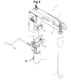
- FIGS. 3 and 4 show a distributor of a continuous casting plant for flat products, specifically for slabs. Unlike the distributor of FIGS. 1 and 2 , the distributor 3 of the FIGS. 3 and 4 a much larger height.
- the plug drive 1 is shown in more detail.
- the lifting rod 4, not shown, is at least partially surrounded by a housing 6, wherein the housing can be attached via the tub supports 8 to the manifold.
- the plug 2, which consists of refractory material (eg ceramic material), is fastened via a screw connection to the outer end of the extension arm 5. Between the housing 6 and the lifting rod 4 two guide elements are integrated, so that an accurate, low-friction guidance of the lifting rod is guaranteed.
- radiation protection plates 22 are provided which protect these components from radiant heat.
- a visual height indicator 23 is shown in the form of a ruler, so that an operator of the manual operation of the plug 2, as well as in automatic mode, an indication of its location is available.
- the Operating personnel also provided a digital indication of the stopper opening.
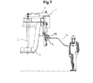
- Fig. 7 is an operator on G foolbühenlomi that adjusts the outflow from a manifold 3 manually.
- the operator moves by means of the hand lever 16, the lifting rod 4, wherein a force increase of about 8 is achieved by the dimensions of the lever lengths of the hand lever 16 and the lever tabs 17.
- the hand lever 17 can be easily removed from the lever tab 16, so that the hand lever when lifting the distributor 3 by means of a crane, not shown, does not constitute a hindrance.
- the hand lever 17 can be swiveled ⁇ 90 ° (see FIG. 12 ) educated.
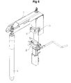
- the linear drive 10 and the connection of the linear drive 10 to the lifting rod 4 are shown in more detail.
- the linear drive comprises an AC hollow shaft servomotor 12, a resolver 24, a gear 13 designed as a spindle nut, and a ball screw as a push spindle 14.
- the rotational movement of the rotor of the electric motor 12 is converted by the gear 13 in a translational movement of the thrust spindle 14, wherein the thrust spindle 14 is connected by means of a mechanical connecting element 15 with the lifting rod 4.
- the lever 16 is connected via lever tabs 17 which are supported on the housing 6 via a rotatable ring 6 a, with the lifting rod 4.
- the ring 6a is axially secured on the housing, but rotatable by 180 °, so that an operator can take different positions relative to the plug drive.
- the connecting element 15 is designed as a cross pin, which engages positively in a likewise aligned transversely to the longitudinal axis 11 groove in the lifting rod 4. Further details are the FIG. 10 and 13 refer to.
- FIG. 9 the anti-rotation of the boom 5 is shown, wherein the boom 5 by means of two Torque supports is secured against rotation.
- the housing 6 is connected to a guide pin 18 oriented parallel to the longitudinal axis 11 of the lifting rod 4.
- the guide pin 18 in conjunction with the guide portion 19 defines the allowable rotational movement of the boom 5 relative to the housing 6 positively, so that it is a form-fitting torque arm.
- the guide region 19 is formed as a groove, wherein the groove covers a segment of a concentric circle about the longitudinal axis 11. This choice of guide range allows for limited cantilever rotation relative to the housing, which is preferably used on long product distributors (see also US Pat FIG.
- the boom 5 is supported via the flange plate 28 and the support bolt 27 on the housing 6, wherein the flange plate 28 is pressed against the boom 5 via the prestressable compression spring 21.
- This torsional moments are frictionally supported so that it is a frictional torque arm.
- the compression spring 21, whose position is determined on the one hand by a spring holder 25 and the other by a spring cup 26, not only serves to form a positive torque arm; Rather, the compression spring 21 also serves as a weight balancing device 21, which compensates for the weight of at least part of the plug drive 1. Due to the weight compensation, the linear drive can be made more compact and less powerful.
- Fig. 11 shows the rotation of FIG. 9 in a sectional view.
- the weight compensation device 20 is designed as a prestressable compression spring 21, which is aligned parallel to the longitudinal axis 11. By the compression spring, the moving masses of the lifting rod 4, the boom 5 and the plug, not shown, partially compensated, so that the linear drive only a reduced force for Shift must apply.
- the compression spring 21 is held and guided on the underside by a spring holder 25 in the form of a threaded pin; on the top is the compression spring in a spring cup 26, so that a lateral deflection of the compression spring 21 is excluded.
- Fig. 13 the connection between the linear drive 10 and the lifting rod 4 is shown enlarged.
- the thrust spindle 14 is connected to the lifting rod 4 via a mechanical connecting element 15, which is designed as a transverse pin lying transversely to the longitudinal axis of the linear drive 10.
- the cross pin engages in a flat transverse groove in the lifting rod 4, so that the thrust spindle 14 is pluggable connected to the lifting rod 4.
- an electrical connector that connects the power electronics - eg a frequency converter - with the linear drive 10.
- the connector has on the side facing away from the electric motor 12 two buttons, through which the thrust spindle 14 can be extended and retracted. This ensures that the linear drive 10 can be easily connected to the lifting rod 4.
- FIG. 14 shows a schematic representation of the lifting forces F and stroke s of the linear drive 10 in the inventive control of the plug drive 1.
- the plug 2 is in the open position, wherein the vertical distance between the plug 2 and the hole stone S Max .
- the linear drive 10 is retracted at a slow speed, wherein the linear drive 10 decelerates the downward movement of the plug 2.
- the linear drive 10 substantially absorbs the weight of the moving masses of the plug drive 1 and the plug 2, ie, the liner drive presses on the lifting rod.
- the linear drive 10 pushes the plug 2, wherein at the time t 9, the linear drive reaches a position s> S 0 , so that the outflow from the distributor is opened.
Landscapes
- Engineering & Computer Science (AREA)
- Mechanical Engineering (AREA)
- Transmission Devices (AREA)
Abstract
Description
Die vorliegende Erfindung betrifft einen elektromechanischen Stopfenantrieb, ein Verfahren zum Ausgleich von Elastizitäten und mechanischen Spielen bei der automatisierten Ansteuerung des Stopfenantriebs sowie die Verwendung des Stopfenantriebs.The present invention relates to an electromechanical plug drive, a method for balancing elasticities and mechanical play in the automated control of the plug drive and the use of the plug drive.
Konkret betrifft die Erfindung einen Stopfenantrieb zum Verschieben eines Stopfens, wodurch der Ausfluss aus einem metallurgischen Gefäß, beispielsweise eines Gießverteilers, verändert werden kann, aufweisend
- eine Hubstange zum Heben und Senken eines Auslegers, wobei der Ausleger auskragend an der Hubstange befestigt ist und der Stopfen am Ausleger befestigt werden kann;
- ein stationäres Gehäuse das einen Längsabschnitt der Hubstange zumindest teilweise umschließt und das Gehäuse über eine Wannenhalterung mit dem metallurgischen Gefäß verbunden werden kann; und
- einen elektromechanischen Linearantrieb zum Verschieben der Hubstange gegenüber dem Gehäuse, wobei die Längsachsen des Linearantriebs und der Hubstange koaxial ausgerichtet sind.
- a lift rod for raising and lowering a boom, wherein the boom is cantilevered to the lift rod and the plug can be attached to the boom;
- a stationary housing which at least partially surrounds a longitudinal section of the lifting rod and the housing can be connected to the metallurgical vessel via a pan holder; and
- an electromechanical linear drive for displacing the lifting rod relative to the housing, wherein the longitudinal axes of the linear drive and the lifting rod are aligned coaxially.
Stopfenantriebe zum Heben und Senken eines typischerweise länglichen Verschlussorgans, dem sogenannten Stopfen, wodurch der Ausfluss aus einem Schmelzengefäß verändert werden kann, sind dem Fachmann aus unterschiedlichen Gebieten der Sekundärmetallurgie und der Gießereitechnik bekannt, insbesondere dem Stranggießen und dem Zweiwalzengießen.Plug drives for raising and lowering a typically elongate closure member, the so-called plug, whereby the effluent from a melt vessel can be changed, are known to those skilled in different fields of secondary metallurgy and foundry technology, in particular continuous casting and two-roll casting.
Weiters betrifft die Erfindung ein Verfahren zum Ausgleich von Elastizitäten und mechanischen Spielen bei der automatisierten Ansteuerung eines Stopfenantriebs. Schließlich betrifft die Erfindung die Verwendung des erfindungsgemäßen Stopfenantriebs zur Durchführung des erfindungsgemäßen Verfahrens.Furthermore, the invention relates to a method for compensating elasticities and mechanical games in the automated control of a plug drive. Finally, the invention relates to the use of the plug drive according to the invention for carrying out the method according to the invention.
Aus der
Aus der
Die Aufgabe der Erfindung ist es, die Nachteile des Stands der Technik zu überwinden und einen preisgünstigen, kompakten, hochdynamischen Stopfenantrieb mit guter Regelbarkeit als auch ein Verfahren zur Ansteuerung des Stopfenantriebs darzustellen, mit dem gegebenenfalls vorhandene Elastizitäten oder Lagerspiele im Stopfenantrieb ausgeglichen werden können. Durch die Kompaktheit soll es möglich sein, den Stopfenantrieb sowohl für Stranggießanlagen für Lang- (z.B. Knüppel-, Vorprofil- oder Vorblockanlagen) und Flachprodukte (z.B. Brammenanlagen) zu verwenden. Durch die hohe Dynamik soll eine gute Regelbarkeit des Stopfenantriebs erreicht werden, sodass der Stopfenantrieb rasch eine Sollposition anfahren bzw. einen Solldurchfluss aus dem metallurgischen Gefäß einstellen kann. Schließlich soll der Stopfenantrieb kostengünstig darstellbar sein.The object of the invention is to overcome the disadvantages of the prior art and to present a low-cost, compact, highly dynamic plug drive with good controllability as well as a method for controlling the plug drive with which any existing elasticities or bearing play in the plug drive can be compensated. The compactness should make it possible to use the plug drive both for continuous casters for long (e.g., billet, pre-profile or bloom) and flat products (e.g., slab plants). Due to the high dynamics, a good controllability of the plug drive is to be achieved so that the plug drive can quickly approach a desired position or set a desired flow from the metallurgical vessel. Finally, the plug drive should be inexpensive to display.
Diese Aufgabe wird durch einen Stopfenantrieb der eingangs genannten Art gelöst, bei dem
- der Linearantrieb als eine bauliche Einheit ausgebildet ist, die einen Elektromotor, vorzugsweise einen Hohlwellen-Servomotor mit einer Gleich-, Wechsel- oder Drehstromanspeisung, ein Getriebe, vorzugsweise eine Kugelumlaufspindel oder eine Spindelmutter, und eine Schubspindel umfasst, wobei das Getriebe zur Umsetzung der Drehbewegung des Elektromotors in eine translatorische Bewegung der Schubspindel ausgebildet ist; und
- der Stopfenantrieb, vorzugsweise der Linearantrieb, eine Kraftmesseinrichtung zur Ermittlung einer Hubkraft und eine Wegemesseinrichtung zur Ermittlung eines Hubwegs aufweist.
- the linear drive is designed as a structural unit, which comprises an electric motor, preferably a hollow shaft servo motor with a DC, AC or three-phase supply, a transmission, preferably a ball screw or a spindle nut, and a thrust spindle, wherein the transmission for implementing the rotational movement the electric motor is formed in a translational movement of the thrust spindle; and
- the plug drive, preferably the linear drive, a force measuring device for determining a lifting force and a path measuring device for determining a stroke.
Es ist vorteilhaft, dass die Wegmesseinrichtung als ein Drehgeber ausgebildet ist, wobei der Drehgeber signaltechnisch mit einem Rotor des Elektromotors verbunden ist und der Drehgeber zwei phasenverschobene Ausgangssignale zur Ermittlung der Drehzahl und der Drehrichtung des Rotors ausgeben kann. Derartige Drehgeber sind dem Fachmann auch unter dem Begriff "Resolver" bekannt. Der Resolver kann auf kompakte Weise vollständig in die bauliche Einheit des Linerantriebs integriert werden, ohne dass dessen Baulänge erhöht wird. Alternativ ist es natürlich ebenfalls möglich, z.B. die Schubspindel, die Hubstange, den Ausleger oder sogar den Stopfen selbst mit einer Wegmesseinrichtung zur Bestimmung des Hubwegs auszubilden.It is advantageous that the displacement measuring device is designed as a rotary encoder, wherein the rotary encoder is technically connected to a rotor of the electric motor and the rotary encoder can output two phase-shifted output signals for determining the rotational speed and the direction of rotation of the rotor. Such rotary encoders are known to the person skilled in the art under the term "resolver". The resolver can be fully integrated into the structural unit of the liner drive in a compact manner without increasing its overall length. Alternatively, it is of course also possible, for example, the thrust spindle, the lifting rod, the boom or even form the plug itself with a path measuring device for determining the stroke.
Es ist vorteilhaft, dass die Kraftmesseinrichtung als eine Strommesseinrichtung ausgebildet ist. Die Strommesseinrichtung misst dabei entweder im Elektromotor selbst oder vorzugsweise in einer Leistungselektronik, die dem Elektromotor zugeordnet ist, zumindest einen Motorstrom. Aus dem Motorstrom kann auf das Drehmoment des Motors rückgeschlossen werden, wobei das Drehmoment über das Getriebe die Hubkraft des Linearantriebs definiert. Auch bei dieser Ausführungsform kann die Kraftmesseinrichtung vollständig in den Elektromotor bzw. dessen Leistungselektronik integriert werden, ohne dass die Baulänge des Linearantriebs erhöht wird. Dazu alternativ könnte z.B. die Hubstange eine Kraftmesseinrichtung zur Ermittlung der Hubkraft aufweisen.It is advantageous that the force measuring device is designed as a current measuring device. The current measuring device measures either at least one motor current in the electric motor itself or preferably in power electronics that is assigned to the electric motor. From the motor current can be deduced on the torque of the motor, wherein the torque via the transmission defines the lifting force of the linear drive. Also in this embodiment, the force measuring device can be completely integrated into the electric motor or its power electronics, without the length of the linear drive is increased. As an alternative, e.g. the lifting rod having a force measuring device for determining the lifting force.
Damit die Montage bzw. Demontage des Linearantriebs einfach möglich ist, ist es vorteilhaft, wenn entweder das Gehäuse des Linearantriebs oder ein elektrischer Verbindungsstecker, der eine Leistungselektronik mit dem Linearantriebs verbinden kann, zumindest zwei Schalter (z.B. Tastschalter) zum Ein-und Ausfahren der Schubspindel aufweisen. Dadurch kann der Hub des Lineantriebs rasch an unterschiedliche Stellungen der Hubstange angepasst werden.Thus, the assembly and disassembly of the linear drive is easily possible, it is advantageous if either the housing of the linear drive or an electrical connector that can connect power electronics with the linear drive, at least two switches (eg push button) for extending and retracting the thrust spindle exhibit. As a result, the stroke of the linear drive can be quickly adapted to different positions of the lifting rod.
Damit ein Stopfenwechsel rasch durchgeführt werden kann, ist der Stopfen an einem Ende des Auslegers lösbar befestigt.For a plug change to be made quickly, the plug is releasably attached to one end of the boom.
Um eine möglichst spielfreie Führung der in vertikaler Richtung verschieblichen Hubstange zu ermöglichen, ist es vorteilhaft, zwischen dem Gehäuse und der Hubstange zumindest ein, bevorzugt mindestens zwei, Führungselemente vorzusehen. Als Führungselemente kommen beispielsweise Linearkugellager, Führungsringe, Gleitlager, federbelastete bzw. vorgespannte Führungsrollen bzw. -kugeln in Frage.In order to enable as play-free guidance of the displaceable in the vertical direction lifting rod, it is advantageous to provide at least one, preferably at least two, guide elements between the housing and the lifting rod. Suitable guide elements are, for example, linear ball bearings, guide rings, plain bearings, spring-loaded or prestressed guide rollers or balls in question.
Um ein manuelles Verschieben des Stopfens bzw. der Hubstange zu ermöglichen, greift ein Handhebel über eine Hebellasche, die am Gehäuse gelenkig abgestützt ist, in die Hubstange ein, sodass die Hubstange mittels des Handhebels manuell verschoben werden kann. Vorzugsweise weist dieser Mechanismus eine Kraftübersetzung i von 3 ≤ i ≤ 10, bevorzugt 5 ≤ i ≤ 8, auf, sodass der Bediener den Stopfen mit geringer Kraftanstrengung verschieben kann.In order to enable a manual displacement of the plug or the lifting rod, a hand lever engages via a lever tab which is pivotally supported on the housing in the lifting rod, so that the lifting rod can be moved manually by means of the hand lever. Preferably, this mechanism has a force transmission i of 3 ≤ i ≤ 10, preferably 5 ≤ i ≤ 8, so that the operator can move the plug with little effort.
Vorzugsweise ist der Handhebel abnehmbar, und bevorzugt um zumindest 180° schwenkbar, ausgebildet. Dadurch kann der Bediener bei der manuellen Bedienung unterschiedliche Positionen zum metallurgischen Gefäß einnehmen.Preferably, the hand lever is removable, and preferably by at least 180 ° pivotally formed. This allows the operator to take different positions to the metallurgical vessel during manual operation.
Damit das Bedienpersonal, insbesondere bei der manuellen Bedienung der Hubstange, eine Indikation der Stopfenposition hat, weist das Gehäuse eine visuelle Höhenanzeige, z.B. in Form eines Lineals, für die Position der Hubstange auf.In order for the operator to have an indication of the stopper position, particularly in the manual operation of the lift rod, the housing has a visual height indication, e.g. in the form of a ruler, for the position of the lifting rod.
Nach dem Stand der Technik kann bei der oben genannten "in-line" Anordnung des Linearantriebs und der Hubstange ein Torsionsmoment, das in Richtung der Längsachse der Hubstange wirkt und beispielsweise von einem exzentrischen Aufsetzen des Stopfens auf der Auslassöffnung, dem sogenannten Lochstein, des metallurgischen Gefäßes herrührt, lediglich über Führungselemente bzw. den Linearantrieb selbst auf das Gehäuse übertragen werden. Im ersten Fall ist es i.A. erforderlich, den Querschnitt der Hubstange eckig auszuführen, damit ein Torsionsmoment von der Hubstange auf ein Führungselement übertragen werden kann. Im zweiten Fall muss der Linearantrieb stärker ausgeführt sein, was sich negativ auf dessen Kompaktheit auswirkt.According to the prior art, in the above-mentioned "in-line" arrangement of the linear drive and the lifting rod, a torsional moment acting in the direction of the longitudinal axis of the lifting rod and, for example, an eccentric placement of the plug on the outlet opening, the so-called perforated brick, of the metallurgical Vessel comes to be transmitted only on guide elements or the linear drive itself to the housing. In the first case it is i.A. required to perform the cross section of the lifting rod angular, so that a torsional moment can be transmitted from the lifting rod to a guide element. In the second case, the linear drive must be made stronger, which has a negative impact on its compactness.
Erfindungsgemäß weist der Stopfenantrieb eine reibschlüssige und/oder eine formschlüssige Drehmomentenstütze auf.According to the invention, the plug drive has a friction-locked and / or a form-fitting torque support.
Die formschlüssige Drehmomentenstütze erfolgt über einen parallel zur Längsachse der Hubstange ausgerichteten Führungsbolzen, der mit dem Gehäuse verbunden ist, und einen Führungsbereich (z.B. eine Führungsnut oder eine Führungsbohrung) im Ausleger zur Führung des Führungsbolzens. Durch den Führungsbolzen und den Führungsbereich wird die Verdrehbarkeit des Auslegers gegenüber dem Gehäuse formschlüssig definiert.The positive torque support takes place via a parallel to the longitudinal axis of the lifting rod aligned Guide pin, which is connected to the housing, and a guide portion (eg a guide groove or a guide bore) in the boom for guiding the guide pin. By the guide pin and the guide area, the rotatability of the boom relative to the housing is defined positively.
Die reibschlüssige Drehmomentenstütze erfolgt über einen parallel zur Längsachse der Hubstange ausgerichteten Stützbolzen, der den Ausleger gegenüber dem Gehäuse abstützt. Dabei wird der Stützbolzen, vorzugsweise durch eine Druckfeder, gegen den Ausleger gepresst, sodass über die Reibung zwischen dem Stützbolzen bzw. einer Flanschplatte, die mit dem Stützbolzen verbunden ist, und der Stützbolzen die Verdrehbarkeit des Auslegers gegenüber dem Gehäuse reibschlüssig definiert.The frictional torque support via a parallel to the longitudinal axis of the lifting rod aligned support pin, which supports the boom relative to the housing. In this case, the support pin, preferably pressed by a compression spring, against the boom, so defined by the friction between the support pin or a flange plate, which is connected to the support bolt, and the support pin, the rotatability of the arm relative to the housing frictionally.
Durch diese Maßnahmen werden einfache Drehmomentenstützen für den Ausleger geschaffen; außerdem kann der Querschnitt der Hubstange beliebig - insbesondere auch rund - ausgeführt werden, sodass die Herstellkosten sinken und aufwändige Führungsrollen bzw. -kugeln zwischen der Hubstange und dem Gehäuse entfallen können. Es ist möglich, die reibschlüssige und die formschlüssige Drehmomentenstütze jeweils einzeln oder in Kombination miteinander zu verwenden.These measures create simple torque supports for the boom; In addition, the cross section of the lifting rod can be arbitrarily - especially round - running, so that the manufacturing costs are reduced and consuming guide rollers or balls between the lifting rod and the housing can be omitted. It is possible to use the frictional and the positive torque arm each individually or in combination with each other.
Der Linearantrieb kann besonders leistungsarm und kompakt ausgeführt werden, wenn der Ausleger mit einer Gewichtsausgleichseinrichtung zum Ausgleich der Gewichtskraft zumindest eines Teiles der bewegten Massen des Stopfenantriebs verbunden ist, und sich die Gewichtsausgleichsvorrichtung am Gehäuse abstützt. Dadurch wird zumindest ein Teil der Gewichtskraft der bewegten Massen des Stopfenantriebs, d.h. der Hubstange, des Auslegers und des Stopfens, kompensiert.The linear drive can be made particularly low-power and compact, when the boom is connected to a weight balancing device to compensate for the weight of at least a portion of the moving masses of the plug drive, and the weight compensation device is supported on the housing. As a result, at least a part of the weight of the moving masses of the plug drive, ie the lifting rod, the boom and the plug, compensated.
Es ist vorteilhaft, wenn die Gewichtsausgleichseinrichtung eine - insbesondere vorspannbare - mechanische, pneumatische oder hydraulische Druckfeder aufweist.It is advantageous if the weight compensation device has a mechanical, pneumatic or hydraulic compression spring, in particular a prestressable one.
Besonders effizient ist die Gewichtskompensation dann, wenn die Längsachse der Druckfeder parallel zur Richtung der Hubstange, d.h. vertikal, ausgerichtet ist.Weight compensation is particularly efficient when the longitudinal axis of the compression spring is parallel to the direction of the lifting rod, i. vertically, is aligned.
Bei einer einfachen Ausführungsform, ist die Position der Druckfeder durch einen Federtopf und einen Federhalter festgelegt, wobei vorzugsweise der Federtopf mit dem Stützbolzen und der Federhalter mit dem Gehäuse verbunden ist. Der Federhalter führt die Druckfeder an dessen innerer Mantelfläche; der Federtopf führt die Drehfeder an dessen äußerer Mantelfläche.In a simple embodiment, the position of the compression spring is determined by a spring cup and a spring holder, wherein preferably the spring cup with the support bolt and the spring holder is connected to the housing. The spring holder guides the compression spring on its inner circumferential surface; the spring cup guides the torsion spring on its outer lateral surface.
Um eine übermäßige Wärmebelastung des Auslegers bzw. des Linearantriebs zu verhindern, ist es vorteilhaft, wenn ein Längsabschnitt des Auslegers und/oder der Linearantrieb von einem Strahlungsschutzblech zumindest teilweise umschlossen ist.In order to prevent excessive heat load on the cantilever or the linear drive, it is advantageous if a longitudinal section of the cantilever and / or the linear drive is at least partially enclosed by a radiation protection plate.
Zur raschen Verbindung bzw. Trennung des Linearantriebs von der Hubstange ist es vorteilhaft, wenn die Schubspindel mittels eines mechanischen Verbindungselements steckbar mit der Hubstange verbindbar ist. Durch das steckbare mechanische Verbindungselement (z.B. einen Zapfen, der mittels Gewinde mit der Schubspindel verbunden ist, der z.B. in eine Quernut in der Hubstange eingreift), kann der Linearantrieb einfach und rasch durch An- bzw. Abstecken montiert bzw. demontiert werden. Alternativ kann der Antrieb auch auf dem Stopfenantrieb verbleiben, sodass nur der elektrische Verbindungsstecker verbunden werden muss.For rapid connection or separation of the linear drive of the lifting rod, it is advantageous if the thrust spindle by means of a mechanical connecting element is pluggable connected to the lifting rod. The plug-in mechanical fastener (e.g., a stud threadedly connected to the push spindle engaging, for example, a transverse groove in the lift rod) allows the linear actuator to be easily and quickly assembled and disassembled by being unplugged. Alternatively, the drive can also remain on the plug drive, so that only the electrical connector must be connected.
Die erfindungsgemäße Aufgabe wird auch durch ein Verfahren zum Ausgleich von Elastizitäten und mechanischen Spielen bei der automatisierten Ansteuerung eines Stopfenantriebs gelöst, das folgende Verfahrensschritte aufweist:
- Einfahren des Linearantriebs bis der Stopfen auf einem Lochstein eines metallurgischen Gefäßes aufsetzt;
- Auslesen der Position des Linearantriebs S0;
- Einfahren des Linearantriebs bis der Stopfen mit einer Nennkraft FNenn gegen den Lochstein gepresst wird;
- Halten des Linearantriebs bei der Nennkraft FNenn für eine Haltezeit tHalten;
- Entlasten des Linearantriebs, sodass der Stopfen mit einer Kraft 0.2FNenn <F<0.8FNenn gegen den Lochstein gepresst wird;
- Füllen des Verteilers mit metallischer Schmelze;
- Ausfahren des Linearantriebs auf eine Soll-Position SSoll > S 0 .
- Retracting the linear drive until the stopper touches a perforated brick of a metallurgical vessel;
- Reading out the position of the linear drive S 0 ;
- Retracting the linear drive until the plug with a nominal force F Nenn is pressed against the perforated brick;
- Holding the linear actuator at nominal force F nominal for a hold time t hold ;
- Relieving the linear drive so that the plug is pressed against the perforated stone with a force 0.2 F nominal <F < 0.8 F nominal ;
- Filling the distributor with metallic melt;
- Extending the linear drive to a setpoint position S setpoint > S 0 .
Unter dem Einfahren bzw. Schließen des Linearantriebs wird das Verschieben der Schubspindel verstanden, wobei der Linearantrieb verkürzt wird; analog wird unter dem Ausfahren bzw. Öffnen des Linearantriebs das Verlängern des Linearantriebs verstanden. Unter der Nennkraft FNenn wird eine Anpresskraft des Stopfens an den Lochstein verstanden, die der Linearantrieb aufbringen kann, ohne dass der Stopfen, der Lochstein oder der Linearantrieb selbst Schaden erleidet. Beispielsweise kann das Einfahren des Linearantriebs bis der Stopfen mit einer Nennkraft FNenn gegen den Lochstein gepresst wird, das Halten des Linearantriebs bei der Nennkraft FNenn, und das Entlasten des Linearantriebs, sodass der Stopfen mit einer Kraft 0.2FNenn <F<0.8FNenn gegen den Lochstein gepresst wird, durch eine Kraftgrenzwertregelung oder durch eine der Positionsregelung überlagerte Kraftregelung realisiert werden.Under the retraction or closing of the linear drive is the displacement of the thrust spindle understood, the linear drive is shortened; Similarly, the extension or opening of the linear drive is understood to mean the lengthening of the linear drive. The nominal force F Nenn is understood to mean a contact pressure of the plug on the perforated brick, which the linear drive can apply without the plug, the perforated brick or the linear drive itself being damaged. For example, retracting the linear actuator until the plug with a nominal force F Nenn is pressed against the stone, holding the linear drive at the nominal force F Nenn , and relieving the linear drive, so that the plug with a force 0.2 F nominal <F < 0.8 F Nenn is pressed against the perforated brick, realized by a force limit control or by the position control superimposed force control.
Für typische Stopfenantriebe ist es zweckmäßig, dass die Haltezeit 2s <tHalten <60s , bevorzugt 5s <tHalten <20s , beträgt. Dadurch wird sichergestellt, dass sich der Stopfen in dem Lochstein setzt, wodurch mechanische Rauhigkeiten zwischen dem Stopfen und dem Lochstein reduziert werden.For typical stopper drives, it is expedient that the holding time is 2 s <t hold <60 s, preferably 5 s <t hold < 20 s . This will ensure that the plug settles in the block, thereby reducing mechanical roughness between the plug and the block.
Um den Stopfenantrieb, den Stopfen und das metallurgische Gefäß nicht zu überlasten ist es vorteilhaft, dass die Nennkraft FNenn kleiner gleich dem Minimum
- der maximal zulässigen Anpresskraft des Stopfens an den Lochstein; und
- der maximalen Schließkraft des Linerantriebs ist.
- the maximum permissible contact pressure of the plug on the perforated brick; and
- the maximum closing force of the liner drive is.
Es ist vorteilhaft, den Stopfenantrieb nach einem der Ansprüche 1 bis 10 in einer Stranggießanlage zur Erzeugung von stranggegossenen Strängen aus Stahl zur Durchführung des Verfahrens nach einem der Ansprüche 11 bis 12 zu verwenden. Dadurch werden mechanische Spiele und Elastizitäten bei der Ansteuerung kompensiert, sodass die Regelgenauigkeit des Stopfenantriebs erhöht wird.It is advantageous to use the plug drive according to one of
Weitere Vorteile und Merkmale der vorliegenden Erfindung ergeben sich aus der nachfolgenden Beschreibung nicht einschränkender Ausführungsbeispiele, wobei auf die folgenden Figuren Bezug genommen wird, die Folgendes zeigen:
-
Fig 1 und 2 je eine perspektivische Darstellung eines Verteilers für eine sechssträngigen Stranggießmaschine für Langprodukte -
Fig 3 und 4 je eine perspektivische Darstellung eines Verteilers für eine Stranggießmaschine für Flachprodukte -
Fig 5 ,6 und8 je eine perspektivische Darstellung eines erfindungsgemäßen Stopfenantriebs -
Fig 7 eine Darstellung eines Stopfenantriebs für Flachprodukte, der von einem Bedienmann manuell bedient werden kann -
Fig 9 eine Darstellung des Details Y vonFig 8 -
Fig 10 eine Darstellung des Details Z vonFig 8 -
Fig 11 eine Schnittdarstellung zuFig 9 -
Fig 12 eine Draufsicht auf einen Stopfenantrieb -
Fig 13 eine Darstellung der Verbindung zwischen dem Linearantrieb und der Hubstange -
Fig 14 ein Diagramm für den Hubweg und die Hubkraft über der Zeit für das erfindungsgemäße Verfahren bei der Ansteuerung eines Stopfenantriebs
-
FIGS. 1 and 2 each a perspective view of a distributor for a six-strand continuous casting machine for long products -
FIGS. 3 and 4 each a perspective view of a distributor for a continuous casting machine for flat products -
Fig. 5 .6 and8th each a perspective view of a plug drive according to the invention -
Fig. 7 a representation of a plug drive for flat products, which can be operated manually by an operator -
FIG. 9 a representation of the detail Y ofFig. 8 -
FIG. 10 a representation of the detail Z ofFig. 8 -
Fig. 11 a sectional view tooFIG. 9 -
FIG. 12 a plan view of a plug drive -
Fig. 13 a representation of the connection between the linear drive and the lifting rod -
FIG. 14 a diagram for the stroke and the lifting force over time for the inventive method in the control of a plug drive
In den
Die
In den
In der
In den
In
In
- 11
- Stopfenantriebplug drive
- 22
- StopfenPlug
- 33
- Verteilerdistributor
- 44
- Hubstangelifting rod
- 55
- Auslegerboom
- 66
- Gehäusecasing
- 6a6a
- Verdrehbarer RingRotatable ring
- 88th
- Wannenhalterungwhen bracket
- 99
- Führungselementguide element
- 1010
- Linearantrieblinear actuator
- 1111
- Längsachselongitudinal axis
- 1212
- Elektromotorelectric motor
- 1313
- Getriebetransmission
- 1414
- Schubspindelpush-rod
- 1515
- Verbindungselementconnecting element
- 1616
- Handhebelhand lever
- 1717
- Hebellaschelever tab
- 1818
- Führungsbolzenguide pins
- 1919
- Führungsbereichguide region
- 2020
- GewichtsausgleichsvorrichtungCounterbalancing apparatus
- 2121
- Druckfedercompression spring
- 2222
- StrahlungsschutzblechRadiation shield
- 2323
- Höhenanzeigeheight indicator
- 2424
- Resolverresolver
- 2525
- Federhalterpenholder
- 2626
- Federtopfspring cup
- 2727
- Stützbolzensupport bolts
- 2828
- Flanschplatteflange
- FF
- Hubkraftlifting capacity
- ss
- Hubwegstroke
- tt
- ZeitTime
Claims (13)
dass der Linearantrieb (10) als eine bauliche Einheit ausgebildet ist, die einen Elektromotor (12), ein Getriebe (13) und eine Schubspindel (14) umfasst, wobei das Getriebe (13) zur Umsetzung einer Drehbewegung des Elektromotors (12) in eine translatorische Bewegung der Schubspindel (14) ausgebildet ist; und
dass der Stopfenantrieb (1), vorzugsweise der Linearantrieb (10), eine Kraftmesseinrichtung zur Ermittlung einer Hubkraft F und eine Wegemesseinrichtung (24) zur Ermittlung eines Hubwegs s umfasst.
in that the linear drive (10) is designed as a structural unit comprising an electric motor (12), a transmission (13) and a push spindle (14), wherein the transmission (13) converts a rotational movement of the electric motor (12) into a translational movement of the thrust spindle (14) is formed; and
in that the stopper drive (1), preferably the linear drive (10), comprises a force measuring device for determining a lifting force F and a path measuring device (24) for determining a stroke s.
dass der Ausleger (5) einen Führungsbereich (19) zur Führung des Führungsbolzens (18) aufweist, wobei der Führungsbolzen (18) mit dem Führungsbereich (19) die Verdrehbarkeit des Auslegers (5) gegenüber dem Gehäuse (6) formschlüssig definiert.Stopper drive according to claim 1, characterized in that a guide pin (18) aligned parallel to the longitudinal axis (11) of the lifting rod (4) is connected to the housing (6);
in that the extension arm (5) has a guide region (19) for guiding the guide pin (18), wherein the guide pin (18) with the guide region (19) defines the rotatability of the cantilever (5) in a form-fitting manner relative to the housing (6).
dass der Stützbolzen (27), vorzugsweise durch eine Druckfeder (21), gegen den Ausleger (5) gepresst wird, wobei der Stützbolzen (27) die Verdrehbarkeit des Auslegers (5) gegenüber dem Gehäuse (6) reibschlüssig definiert.Stopper drive according to one of the preceding claims, characterized in that a parallel to the longitudinal axis (11) of the lifting rod (4) aligned support pin (27) with the housing (6) is connected;
in that the support bolt (27) is pressed against the extension arm (5), preferably by a compression spring (21), wherein the support bolt (27) frictionally defines the rotatability of the extension arm (5) relative to the housing (6).
Priority Applications (2)
| Application Number | Priority Date | Filing Date | Title |
|---|---|---|---|
| EP11183395A EP2574414A1 (en) | 2011-09-30 | 2011-09-30 | Electromechanical stopper drive |
| PCT/EP2012/069015 WO2013045520A1 (en) | 2011-09-30 | 2012-09-27 | Electromechanical stopper drive |
Applications Claiming Priority (1)
| Application Number | Priority Date | Filing Date | Title |
|---|---|---|---|
| EP11183395A EP2574414A1 (en) | 2011-09-30 | 2011-09-30 | Electromechanical stopper drive |
Publications (1)
| Publication Number | Publication Date |
|---|---|
| EP2574414A1 true EP2574414A1 (en) | 2013-04-03 |
Family
ID=47002844
Family Applications (1)
| Application Number | Title | Priority Date | Filing Date |
|---|---|---|---|
| EP11183395A Withdrawn EP2574414A1 (en) | 2011-09-30 | 2011-09-30 | Electromechanical stopper drive |
Country Status (2)
| Country | Link |
|---|---|
| EP (1) | EP2574414A1 (en) |
| WO (1) | WO2013045520A1 (en) |
Cited By (3)
| Publication number | Priority date | Publication date | Assignee | Title |
|---|---|---|---|---|
| EP3231532A1 (en) * | 2016-04-12 | 2017-10-18 | Primetals Technologies Austria GmbH | Methods of starting and stopping a multi-strand continuous casting machine, and shared sealing drive and multi-strand continuous casting machine |
| CN108568515A (en) * | 2018-06-14 | 2018-09-25 | 刘中原 | One kind precisely aligning stopper device and stopper rod of tundish Alignment Process |
| WO2023194602A1 (en) * | 2022-04-08 | 2023-10-12 | Vesuvius - Sert, Sas | Control device for a metallurgical vessel stopper-rod |
Families Citing this family (2)
| Publication number | Priority date | Publication date | Assignee | Title |
|---|---|---|---|---|
| DE102013218345B4 (en) | 2013-09-12 | 2021-02-04 | Sms Group Gmbh | Device for closing a drain opening in a metallurgical vessel |
| CN106694865A (en) * | 2017-02-06 | 2017-05-24 | 浙江杭机铸造有限公司 | Stationary ladle pulling and stopping device |
Citations (10)
| Publication number | Priority date | Publication date | Assignee | Title |
|---|---|---|---|---|
| DE3421344A1 (en) * | 1984-06-08 | 1985-12-12 | Krupp Stahl Ag, 4630 Bochum | Method and apparatus for the automatic filling of a continuous casting mould for the initial casting of a strand |
| JPH02220751A (en) * | 1989-02-21 | 1990-09-03 | Nippon Steel Corp | Apparatus and method for controlling casting in continuous casting machine |
| US4953761A (en) * | 1988-09-27 | 1990-09-04 | Inductotherm Corp. | Stopper rod spatial control mechanism |
| US5312090A (en) * | 1992-12-14 | 1994-05-17 | Cmi International | Apparatus and method for controlling a stopper rod of a bottom pouring vessel |
| JPH06328230A (en) * | 1993-05-19 | 1994-11-29 | Kubota Corp | Molten metal tapping part in molten metal holding furnace |
| EP0734801A1 (en) * | 1995-03-28 | 1996-10-02 | Concast Standard Ag | Device for controlling an inflow of metal by means of a stopper |
| EP1819466B1 (en) | 2004-11-30 | 2009-07-15 | DANIELI & C. OFFICINE MECCANICHE S.p.A. | Control device of a stopper-rod |
| US20100282784A1 (en) * | 2009-05-10 | 2010-11-11 | Paiva Marcelo Albano | Stopper Rod Positioning and Control Apparatus for Control of Molten Metal Flow Through a Nozzle |
| CN201735786U (en) * | 2010-08-26 | 2011-02-09 | 西安秦翔科技有限责任公司 | Leading screw-motor servo automatic control stopper adjusting actuator |
| EP1426126B1 (en) | 2002-12-04 | 2011-03-23 | Societe D'etudes Et De Realisations Techniques S.E.R.T. | Control assembly for a closing member in a continuous casting machine, and corresponding continuous casting machine |
-
2011
- 2011-09-30 EP EP11183395A patent/EP2574414A1/en not_active Withdrawn
-
2012
- 2012-09-27 WO PCT/EP2012/069015 patent/WO2013045520A1/en active Application Filing
Patent Citations (10)
| Publication number | Priority date | Publication date | Assignee | Title |
|---|---|---|---|---|
| DE3421344A1 (en) * | 1984-06-08 | 1985-12-12 | Krupp Stahl Ag, 4630 Bochum | Method and apparatus for the automatic filling of a continuous casting mould for the initial casting of a strand |
| US4953761A (en) * | 1988-09-27 | 1990-09-04 | Inductotherm Corp. | Stopper rod spatial control mechanism |
| JPH02220751A (en) * | 1989-02-21 | 1990-09-03 | Nippon Steel Corp | Apparatus and method for controlling casting in continuous casting machine |
| US5312090A (en) * | 1992-12-14 | 1994-05-17 | Cmi International | Apparatus and method for controlling a stopper rod of a bottom pouring vessel |
| JPH06328230A (en) * | 1993-05-19 | 1994-11-29 | Kubota Corp | Molten metal tapping part in molten metal holding furnace |
| EP0734801A1 (en) * | 1995-03-28 | 1996-10-02 | Concast Standard Ag | Device for controlling an inflow of metal by means of a stopper |
| EP1426126B1 (en) | 2002-12-04 | 2011-03-23 | Societe D'etudes Et De Realisations Techniques S.E.R.T. | Control assembly for a closing member in a continuous casting machine, and corresponding continuous casting machine |
| EP1819466B1 (en) | 2004-11-30 | 2009-07-15 | DANIELI & C. OFFICINE MECCANICHE S.p.A. | Control device of a stopper-rod |
| US20100282784A1 (en) * | 2009-05-10 | 2010-11-11 | Paiva Marcelo Albano | Stopper Rod Positioning and Control Apparatus for Control of Molten Metal Flow Through a Nozzle |
| CN201735786U (en) * | 2010-08-26 | 2011-02-09 | 西安秦翔科技有限责任公司 | Leading screw-motor servo automatic control stopper adjusting actuator |
Cited By (3)
| Publication number | Priority date | Publication date | Assignee | Title |
|---|---|---|---|---|
| EP3231532A1 (en) * | 2016-04-12 | 2017-10-18 | Primetals Technologies Austria GmbH | Methods of starting and stopping a multi-strand continuous casting machine, and shared sealing drive and multi-strand continuous casting machine |
| CN108568515A (en) * | 2018-06-14 | 2018-09-25 | 刘中原 | One kind precisely aligning stopper device and stopper rod of tundish Alignment Process |
| WO2023194602A1 (en) * | 2022-04-08 | 2023-10-12 | Vesuvius - Sert, Sas | Control device for a metallurgical vessel stopper-rod |
Also Published As
| Publication number | Publication date |
|---|---|
| WO2013045520A1 (en) | 2013-04-04 |
Similar Documents
| Publication | Publication Date | Title |
|---|---|---|
| EP2574414A1 (en) | Electromechanical stopper drive | |
| DE4138740A1 (en) | METHOD AND DEVICE FOR CONTINUOUSLY casting slabs or blocks | |
| EP1843867B1 (en) | Tundish car comprising a lifting mechanism for a tundish | |
| CH639881A5 (en) | METHOD FOR CHANGING A STRING CROSS-SIZE FORMAT AND CHOCOLATE FOR IMPLEMENTING THE METHOD. | |
| DE4208061C2 (en) | Induction furnace for melting and pouring substances in a non-reactive atmosphere | |
| EP0044291B1 (en) | Means for measuring the frictional force between the mould and the strand at continuous casting | |
| DE2742455C3 (en) | Support guide frame in a continuous steel casting plant | |
| DE2557769A1 (en) | INTERMEDIATE TANK CARRIAGE FOR METAL, IN PARTICULAR STEEL CASTING PLANTS | |
| EP3833787B1 (en) | Method of operating a converter and support device for a converter | |
| EP0077319B1 (en) | Electric furnace | |
| AT516412B1 (en) | Strand guide roller unit for a continuous casting machine | |
| DE202010000301U1 (en) | Device for dosing a gas mixture | |
| DE2543168C3 (en) | Mobile pouring device | |
| EP0073184B1 (en) | Plate mould of a continuous casting plant | |
| EP3532425B1 (en) | Method for the compensation of diagonal pull in cranes | |
| DE102008057818A1 (en) | Continuous casting device and continuous casting process | |
| DE10160636A1 (en) | Process for adjusting the casting gap on a strand guide of a continuous casting installation comprises adjusting the gap before casting using a path measuring system, and continuously adjusting the gap after casting under operational load | |
| EP1062723A1 (en) | Hoisting drive for use in the iron and steel industry | |
| EP3231532B1 (en) | Methods of starting and stopping a multi-strand continuous casting machine, and shared sealing drive and multi-strand continuous casting machine | |
| EP3782748A1 (en) | Drive device for a stopper in a metallurgical vessel | |
| DE1758971B1 (en) | Vacuum furnace with weight-dependent control of the batch feed | |
| DE2408894A1 (en) | DEVICE FOR LIFTING AND SWIVELING A METALLURGICAL VESSEL | |
| DE102009033934B3 (en) | Device for temporarily sealing a tap hole, which has a first internal diameter and is provided in the bottom of a metallurgical furnace, for filling the tap hole with free-flowing fire-resistant compound, comprises sealing and filling pipe | |
| EP2358645A1 (en) | Glass feeder device and method for moving a plunger of a glass feeder device | |
| EP1044743B1 (en) | Hot chamber die casting machine |
Legal Events
| Date | Code | Title | Description |
|---|---|---|---|
| PUAI | Public reference made under article 153(3) epc to a published international application that has entered the european phase |
Free format text: ORIGINAL CODE: 0009012 |
|
| AK | Designated contracting states |
Kind code of ref document: A1 Designated state(s): AL AT BE BG CH CY CZ DE DK EE ES FI FR GB GR HR HU IE IS IT LI LT LU LV MC MK MT NL NO PL PT RO RS SE SI SK SM TR |
|
| AX | Request for extension of the european patent |
Extension state: BA ME |
|
| STAA | Information on the status of an ep patent application or granted ep patent |
Free format text: STATUS: THE APPLICATION IS DEEMED TO BE WITHDRAWN |
|
| 18D | Application deemed to be withdrawn |
Effective date: 20131005 |