EP2574257A1 - Fensterdekoration - Google Patents
Fensterdekoration Download PDFInfo
- Publication number
- EP2574257A1 EP2574257A1 EP12006486A EP12006486A EP2574257A1 EP 2574257 A1 EP2574257 A1 EP 2574257A1 EP 12006486 A EP12006486 A EP 12006486A EP 12006486 A EP12006486 A EP 12006486A EP 2574257 A1 EP2574257 A1 EP 2574257A1
- Authority
- EP
- European Patent Office
- Prior art keywords
- window
- boom
- building
- decoration according
- window decoration
- Prior art date
- Legal status (The legal status is an assumption and is not a legal conclusion. Google has not performed a legal analysis and makes no representation as to the accuracy of the status listed.)
- Granted
Links
Images

Classifications
-
- A—HUMAN NECESSITIES
- A47—FURNITURE; DOMESTIC ARTICLES OR APPLIANCES; COFFEE MILLS; SPICE MILLS; SUCTION CLEANERS IN GENERAL
- A47H—FURNISHINGS FOR WINDOWS OR DOORS
- A47H27/00—Boxes, shelves, holders or similar supports for holding flowers
Definitions
- the object of the invention is therefore to improve the mentioned disadvantages of the prior art.
- the invention relates to a window decoration comprising a boom, which is assigned to a window element of the building in front of an outer wall of a building and serves as a carrier for a decoration or a decorative element, in particular a miniature garden, wherein the boom comprises a fastening means, wherein the fastening means connected to the boom and wherein the fastening means is preferably attached directly to the building by clamping force or suction or adhesive force, in particular while avoiding machining or damage to the building.
- boom can thus be created with greater freedom of design, the desired decoration.
- boom come a variety of materials in question, which meet the respective decorative requirements for tightness, capacity and weight.
- boom for receiving a Auflegers are conceivable.
- the boom does not exceed a maximum boom length of 30cm to 70cm, especially 50cm.
- This length is about the reach of a person who is at the window and should be able to reach with their arms the entire usable area of the boom.
- the boom is formed flat and / or at least partially, preferably completely encircling, is equipped with edge-limiting elements.
- a window garden or miniature garden can best be created in one level.
- a boundary helps this, to prevent the falling of decorative components and / or to avoid contamination.
- the edge boundary can be additionally increased in the areas which are not accessible from the window, ie at the other edge areas which are not opposite the window.
- the boom has at least one joint means, wherein the hinge means achieve that the boom is in a vertical position, in particular in front of the window can be folded up.
- the boom if it is not needed for example, or if disassembly or assembly is to take place, be folded up in front of the window.
- the boom has at least one rotary bearing, wherein the rotary bearing achieved that the boom is rotatable in front of the window in a substantially horizontal plane.
- the boom can be rotated by the user in front of the window in a plane. In this way, hard to reach areas are easy to work and the dimension of the boom is not limited to the range of the user's arm.
- the boom has at least one drainage system, in particular a sipe and / or a drainage channel, the drainage system allows targeted drainage and in particular to a drainage system of a building can be connected.
- a drainage system ensures that, for example, during rain or during the casting of a miniature garden, water does not run beyond the boom, resulting in building pollution and / or nuisance from, for example, flats below.
- the drainage system can be connected to a drainage system of a building, for example to a gutter, an automatic drainage can take place.
- collection containers are on the boom or inside the apartment conceivable.
- a cover and / or a protective hood and / or a greenhouse hood is provided, wherein the hood is individually or jointly releasably and / or hingedly connected to the boom.
- Guard against hail, cover against direct sunlight or a greenhouse function represent further expedient versions, which enhance the added value for the recreation area according to the invention.
- a support surface and / or accessories for animals in particular a padding and / or a cat tree and / or devices for providing food are integrated and / or placeable.
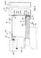
- FIG. 1 a first embodiment of a window decoration 1 is shown. It is in the section FIG. 1 a window element 2 of a building 3 is shown, wherein from the window element 2, a section of a window frame 2a, a portion of a sash 2b and a arranged on an outer side 4 of the building 3 window sill 2c are visible in section. To maintain the clarity of the presentation, a hatched representation of the individual components has been omitted in the figures in part. An outer wall 5 of the building 3 is indicated by dashed lines.
- the window decoration 1 comprises a fastening means 6 and a jib 7.
- the jib 7 is formed as a trough 8 and forms with a portion 7a a supporting member 9 of the fastening means 6, in which the boom 7 between a first module 6a and a second module 6b of the fastening means 6 is integrated by the fact that the first module 6a and the second module 6b are connected at a first attachment point 7b and at a second attachment point 7c to the boom 7 and that the boom 7 thereby forces from the first module 6a to the second module 6b and vice versa transfers.
- the second module 6b of the fastening means 6 is designed as an L-shaped angle, which is guided through an opening 7d in a bottom 7e of the arm 7 and with a wall 7f of the boom 7th is screwed.
- the boom 7 in the wall 7f a hole 7g, through which a clamping means 10 is guided, which also passes through a slot 11 which is executed on the second module 6b of the fastening means 6.
- a distance 12 between the bottom 7e of the boom 7 and a short leg 13 of the second module 6b of the fastening means 6 is adjustable and adaptable to the respective window sill 2c.
- the tensioning means comprises in particular a screw and a nut which can be screwed onto the screw, so that the components to be connected can be clamped together.
- the first module 6a of the fastener 6 is also adaptable by means of further clamping means 14, 15 and 16 in its length and its span to the respective circumstances or requirements.
- a trailer 22 is shown, which is inserted into the trough-shaped boom 7 and even receives a decorative element 23.
- the boom is designed as a flat component, wherein it is also provided in particular to perform the boom to increase its stability as a profiled or ribbed component.
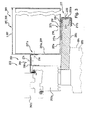
- FIG. 2 a second embodiment of a window decoration 101 is shown. It is in the section FIG. 2 a window element 102 of a building 103 is shown, wherein from the window element 102, a portion of a frame 102a, a portion of a sash 102b and an outer side 104 of the building 103 arranged window sill 102c are visible in section. An outer wall 105 of the building 103 is indicated by dashed lines.
- the window decoration 101 comprises a fastening means 106 and a cantilever 107.
- the cantilever 107 is formed as a trough 108 and forms with a portion 107a a supporting component 109 of the fastening means 106, in which the cantilever 107 between a first module 106a and a second module 106b of the fastener 106 is integrated by connecting the first module 106a and the second module 106b to the cantilever 107 at a first attachment point 107b and a second attachment point 107c and that the cantilever 107 thereby receives forces from the first module 106a to the second module 106b and vice versa transmits.
- the second module 106b of the fastening means 206 is designed as an adjustable clamp unit 117, the clamp jaws 117a and 117b are connected by a clamping means 118 with a wall 107h of the boom 107, wherein the Clip jaws 117a, 117b have slots 119 and 120 to be relatively displaceable relative to the clamping means 118.
- the first module 106a of the fastening means 106 can also be adapted to the respective conditions by means of further tensioning means 114 and 116.
- the cantilever 107 connects the first module 106a and the second module 106b of the fastener 106 in a region which is perpendicular to the outer wall 105 farther from the outer wall 105 than a drip edge 121 of the window sill 102c.
- the boom 107 is in the FIG. 2 shown broken to make the presentation more compact.
- the cantilever 107 has a length L107 which is measured in a direction perpendicular to the outer side 104 of the outer wall 105. According to unillustrated embodiments, the boom is not designed as a tub, but as a U-shaped channel or as a container.
- FIG. 3 a third embodiment of a window decoration 201 is shown. It is in the section FIG. 3 a window element 202 of a building 203 is shown, wherein from the window element 202, a section of a frame 202a, a section of a sash 202b and an outer side 204 of the building 203 arranged window sill 202c are visible in section. An outer wall 205 of the building 203 is indicated by dashed lines.
- the window decoration 201 comprises a fastening means 206 and a cantilever 207.
- the cantilever 207 is formed as a trough 208 and forms with a portion 207a a supporting member 209 of the fastening means 206, in which the cantilever 207 between a first module 206a and a second module 206b of the fastener 206 is integrated with the first module 206a and the second module 206b are connected to the boom 207 at a first attachment point 207b and at a second attachment point 207c and that the boom 207 thereby forces from the first module 206a to the second module 206b and vice versa.
- the second module 206b of the fastening means 206 is as adjustable clamp unit 217 executed, the clamp jaws 217a and 217b are connected by a clamping means 218 with a bottom 207e of the boom 207, wherein the clamp jaws 217a, 217b slots 219 and 220 have to be slidable with loose clamping means relative to the boom 207 and each other.
- the first module 206a of the fastening means 206 can also be adapted to the respective conditions by means of further tensioning means 214 and 216.
- the fastening means 206 for differently shaped arms, provided that they have bores for fastening the first and the second module 206a, 206b of the fastening means 206 in suitable areas.
- Characteristic of the third embodiment is that the boom 207 rests with the interposition of the second module 206b on the window sill 202c and projects beyond the window sill 203c.
- Such an attachment is particularly suitable for cantilevers which have a large length L207 and project to more than 50% of their length L207 over a drip edge 221 of the window cornice 202c.
- the invention provides that the cantilever L207 is up to 120 cm.
- the cantilever alternatively or in addition to the trailer burdening decorative element between the jaw 217a and the window sill 202c a compensation element 224 is provided.
- the compensation element 224 allows a horizontal alignment of the bottom 207e of the boom 207 on the window sill 202c.
- the second module of the fastener analogous to that in the FIG. 1 to execute execution variant shown or form as arranged on the bottom of the boom suction cup, which sucks on the window sill.
- the first module of the fastening means is designed in each case as a staple unit which engages the lower spar of the window frame of the window element with two clamping jaws.
- the boom is like that is integrated in the fastening means that this forms a central, lying between the flange to the building component of the fastener
- the first and the second module of the fastener can be used in the same form for a variety of booms, since it is only necessary, this two appropriate locations of the boom.
- the clamp jaws or connecting webs of the fastening means are formed flat and, according to a variant, not shown, to increase their stability at least partially a profiling or reinforcing ribs.
Landscapes
- Door And Window Frames Mounted To Openings (AREA)
- Load-Bearing And Curtain Walls (AREA)
Description
- Aus dem Stand der Technik, beispielsweise aus der
EP 2 299 045 A1 des Anmelders, sind Halterungen bekannt, welche unter minimaler bis vermiedener mechanischer Manipulation einer Außenfassade eines Gebäudes oder eines ein Fensterelements die Befestigung von kleineren Gegenständen erlauben. - Die immer stärker werdenden Anforderungen, insbesondere im Bereich dicht besiedelter Großstädte, welche Personen an den Naherholungsraum zu ihrem Wohnbereich stellen, verlangen stets nach neuen Erfindungen, um beispielsweise auch das Hobby eines Klein- bzw. Miniaturgartens unabhängig von den Grundstücksgegebenheiten oder Wohnungen in Mehrfamilienhäusern betreiben zu können.
- Im Stand der Technik sind längliche Blumenkästen bekannt, welche vor einem Fenster in entsprechenden Halterungen angeordnet werden können. Diese Blumenkästen bieten jedoch allgemein eine zu geringe Flexibilität in ihrer Nutzfläche und Gestaltungsfreiheit. Darüber hinaus stellen die oftmals auftretenden Verschmutzungen, welche durch aus den Blumenkästen bei Regen oder beim Gießen ausgeschwämmte Erde entstehen, oftmals einen Anlass für Streitigkeiten dar.
- Aufgabe der Erfindung ist es daher, die genannten Nachteile des Standes der Technik zu verbessern.
- Diese Aufgabe wird durch eine Fensterdekoration nach dem. Schutzanspruch 1 gelöst. Vorteilhafte Weiterbildungen sowie zweckmäßige Ausgestaltungen sind in den abhängigen Ansprüchen angegeben.
- Die Erfindung betrifft eine Fensterdekoration umfassend einen Ausleger, welcher vor einer Außenwand eines Gebäudes einem Fensterelement des Gebäudes zugeordnet ist und als Träger für eine Dekoration bzw. ein Dekorationselement, insbesondere einen Miniaturgarten dient wobei der Ausleger ein Befestigungsmittel umfasst, wobei das Befestigungsmittel mit dem Ausleger verbunden ist und wobei das Befestigungsmittel vorzugsweise durch Klemmkraft oder Saugkraft oder Klebkraft insbesondere unter Vermeidung einer Bearbeitung oder Beschädigung des Gebäudes direkt an dem Gebäude befestigt ist.
- Auf dem Ausleger kann somit mit größerer Gestaltungsfreiheit die gewünschte Dekoration angelegt werden. Als Ausleger kommen verschiedenste Materialien in Frage, welche den jeweiligen Dekorationsanforderungen an Dichtigkeit, Tragkraft und Gewicht genügen. Auch mehrere Ausleger zur Aufnahme eines Auflegers sind denkbar.
- In einer Weiterbildung der Fensterdekoration ist vorgesehen, dass der Ausleger eine maximale Auslegerlänge von 30cm bis 70cm, insbesondere 50cm nicht überschreitet.
- Diese Länge ist in etwa die Reichweite einer Person, welche am Fenster steht und mit ihren Armen die komplette Nutzfläche des Auslegers erreichen können soll.
- In einer Weiterbildung der Fensterdekoration ist vorgesehen, dass der Ausleger flächig ausgebildet ist und/oder zumindest teilweise, vorzugsweise vollständig umlaufend, mit randbegrenzenden Elementen ausgestattet ist.
- Beispielsweise ein Fenstergarten bzw. Miniaturgarten lässt sich am Besten in einer Ebene anlegen. Soweit eine Randbegrenzung vorgesehen ist hilf diese, das Herunterfallen von Dekorationsbestandteilen zu verhindern und/oder Verschmutzungen zu vermeiden. Die Randbegrenzung kann dabei in den Bereichen, welche vom Fenster aus nicht zugänglich sein sollen, also an den sonstigen Randbereichen, welche nicht gegenüber des Fensters liegen, zusätzlich erhöht sein.
- Hierdurch werden beispielsweise Terrassierungen ermöglicht.
- In einer Weiterbildung der Erfindung ist vorgesehen, dass der Ausleger über mindestens ein Gelenkmittel verfügt, wobei die Gelenkmittel erzielen, dass der Ausleger in eine senkrechte Stellung, insbesondere vor das Fenster hochklappbar ist.
- Auf diese Weise kann der Ausleger, wenn er beispielsweise nicht benötigt wird oder wenn eine Demontage oder Montage erfolgen soll, vor das Fenster hochgeklappt werden.
- In einer Weiterbildung der Fensterdekoration ist vorgesehen, dass der Ausleger über mindestens ein Rotationslager verfügt, wobei das Rotationslager erzielt, dass der Ausleger vor dem Fenster in einer im Wesentlichen horizontalen Ebene drehbar ist.
- Durch den Einsatz eines Rotationslagers kann der Ausleger durch den Benutzer vor dem Fenster in einer Ebene gedreht werden. Auf diese Weise sind auch schwer zugängliche Bereiche leichte zu bearbeiten und die Dimension des Auslegers ist nicht auf die Reichsweite des Armes des Benutzers beschränkt.
- In einer Weiterbildung der Fensterdekoration ist vorgesehen, dass der Ausleger über mindestens ein Entwässerungssystem, insbesondere einen Siffon und/oder eine Entwässerungsrinne verfügt, wobei das Entwässerungssystem eine gezielte Entwässerung ermöglicht und insbesondere an ein Entwässerungssystem eines Gebäudes anschließbar ist.
- Ein Entwässerungssystem sorgt dafür, dass beispielsweise bei Regen oder beim Gießen eines Miniaturgartens kein Wasser über den Ausleger hinaus läuft und es dadurch zu Gebäudeverschmutzungen und/oder Belästigungen von beispielsweise darunter liegenden Wohnungen kommt. Soweit das Entwässerungssystem an ein Entwässerungssystem eines Gebäudes, beispielsweise an eine Dachrinne anschließbar ist, kann eine automatische Entwässerung erfolgen. Alternativ sind aber auch Auffangbehälter am Ausleger oder innerhalb der Wohnung denkbar.
- In einer Weiterbildung der Fensterdekoration ist vorgesehen, dass eine Abdeckhaube und/oder eine Schutzhaube und/oder eine Gewächshaushaube vorgesehen ist, wobei die Haube je einzeln oder gemeinsam lösbar und/oder klappbar mit dem Ausleger verbunden ist.
- Schutzhauben gegen Hagel, Abdeckung gegen direkte Sonneneinstrahlung oder eine Gewächshausfunktion stellen weitere zweckmäßige Ausführungen dar, welche den erfindungsgemäßen Mehrwert für den Naherholungsraum verstärken.
- In einer zusätzlichen Weiterbildung bzw. Aufrührung ist vorgesehen, dass eine Auflagefläche und/oder Accessoires für Tiere, insbesondere eine Polsterung und/oder ein Kratzbaum und/oder Vorrichtungen zur Bereitstellung von Nahrungsmitteln integriert und/oder platzierbar sind.
- Die Nutzung dieser Anordnung als "Katzenbalkon" stellt eine weitere zweckmäßige Ausführungsform dar. Dabei kann entweder ein reiner Ruheplatz mit oder ohne sonstige Dekoration ausgeführt werden oder es können auch funktionelle Elemente wie beispielsweise ein Kratzbaum, eine Wassertränke oder andere Elemente vorgesehen werden. Soweit diese Elemente verliersicher in die Vorrichtung integriert werden stellen diese auch keine zusätzliche Gefahr durch herunterfallende Bestandteile für die Umgebung dar.
- Weitere Einzelheiten der Erfindung werden in der Zeichnung anhand von schematisch dargestellten Ausführungsbeispielen beschrieben.
- Hierbei zeigen:
-
Figuren 1 bis 3 : in schematischer Darstellung drei Ausführungsvarianten von erfindungsgemäßen Fensterdekorationen. - In der
Figur 1 ist eine erste Ausführungsvariante einer Fensterdekoration 1 gezeigt. Ausschnittsweise ist in derFigur 1 ein Fensterelement 2 eines Gebäudes 3 gezeigt, wobei von dem Fensterelement 2 ein Abschnitt eines Blendrahmens 2a, ein Abschnitt eines Flügelrahmens 2b und ein an einer Außenseite 4 des Gebäudes 3 angeordneter Fenstersims 2c im Schnitt sichtbar sind. Zur Erhaltung der Übersichtlichkeit der Darstellung wurde in den Figuren teilweise auf eine schraffierte Darstellung der einzelnen Bauteile verzichtet. Eine Außenwand 5 des Gebäudes 3 ist mit gestrichelten Linien angedeutet. Die Fensterdekoration 1 umfasst ein Befestigungsmittel 6 und einen Ausleger 7. Hierbei ist der Ausleger 7 als Wanne 8 ausgebildet und bildet mit einem Abschnitt 7a ein tragendes Bauteil 9 des Befestigungsmittels 6, in dem der Ausleger 7 zwischen ein erstes Modul 6a und ein zweites Modul 6b des Befestigungsmittels 6 dadurch integriert ist, dass das erste Modul 6a und das zweite Modul 6b an einer ersten Befestigungsstelle 7b und an einer zweiten Befestigungsstelle 7c mit dem Ausleger 7 verbunden sind und dass der Ausleger 7 hierdurch Kräfte von dem ersten Modul 6a zu dem zweiten Modul 6b und umgekehrt überträgt. Zur Anpassung der Fensterdekoration 1 an unterschiedliche bauliche Gegebenheiten bzw. unterschiedliche Fensterelemente ist das zweite Modul 6b des Befestigungsmittels 6 als L-förmiger Winkel ausgeführt, welcher durch eine Öffnung 7d in einem Boden 7e des Auslegers 7 geführt ist und mit einer Wandung 7f des Auslegers 7 verschraubt ist. Hierzu weist der Ausleger 7 in der Wandung 7f eine Bohrung 7g auf, durch welche ein Spannmittel 10 geführt ist, welches auch ein Langloch 11 durchgreift, welches an dem zweiten Modul 6b des Befestigungsmittels 6 ausgeführt ist. Auf diese Weise ist ein Abstand 12 zwischen dem Boden 7e des Auslegers 7 und einem kurzen Schenkel 13 des zweiten Moduls 6b des Befestigungsmittels 6 einstellbar und an den jeweiligen Fenstersims 2c anpassbar. Das Spannmittel umfasst insbesondere ein Schraube und eine auf die Schraube aufschraubbare Mutter, so dass die zu verbindenden Bauteile miteinander verspannt werden können. Selbstverständlich sieht die Erfindung auch die Verwendung anderer Spannmittel vor, welche geeignet sind, die zu verbindenden Bauteile zueinander in Position zu halten. Das erste Modul 6a des Befestigungsmittels 6 ist mittels weiterer Spannmittel 14, 15 und 16 ebenfalls in seiner Länge und seiner Spannweite an die jeweiligen Gegebenheiten bzw. Anforderungen anpassbar. In derFigur 1 ist weiterhin ein Aufleger 22 gezeigt, welcher in den wannenförmigen Ausleger 7 eingesetzt ist und selbst ein Dekorationselement 23 aufnimmt. Erfindungsgemäß ist es auch vorgesehen, das Dekorationselement direkt in den Ausleger einzusetzen. Gemäß einer nicht dargestellten Ausführungsvariante ist der Ausleger als flächiges Bauteil ausgebildet, wobei es insbesondere auch vorgesehen ist, den Ausleger zur Erhöhung seiner Stabilität als profiliertes bzw. mit Rippen versehenes Bauteil auszuführen. - In der
Figur 2 ist eine zweite Ausführungsvariante einer Fensterdekoration 101 gezeigt. Ausschnittsweise ist in derFigur 2 ein Fensterelement 102 eines Gebäudes 103 gezeigt, wobei von dem Fensterelement 102 ein Abschnitt eines Blendrahmens 102a, ein Abschnitt eines Flügelrahmens 102b und ein an einer Außenseite 104 des Gebäudes 103 angeordneter Fenstersims 102c im Schnitt sichtbar sind. Eine Außenwand 105 des Gebäudes 103 ist mit gestrichelten Linien angedeutet. Die Fensterdekoration 101 umfasst ein Befestigungsmittel 106 und einen Ausleger 107. Hierbei ist der Ausleger 107 als Wanne 108 ausgebildet und bildet mit einem Abschnitt 107a ein tragendes Bauteil 109 des Befestigungsmittels 106, in dem der Ausleger 107 zwischen ein erstes Modul 106a und ein zweites Modul 106b des Befestigungsmittels 106 dadurch integriert ist, dass das erste Modul 106a und das zweite Modul 106b an einer ersten Befestigungsstelle 107b und an einer zweiten Befestigungsstelle 107c mit dem Ausleger 107 verbunden sind und dass der Ausleger 107 hierdurch Kräfte von dem ersten Modul 106a zu dem zweiten Modul 106b und umgekehrt überträgt. Zur Anpassung der Fensterdekoration 101 an unterschiedliche bauliche Gegebenheiten bzw. unterschiedliche Fensterelemente ist das zweite Modul 106b des Befestigungsmittels 206 als verstellbare Klammereinheit 117 ausgeführt, deren Klammerbacken 117a und 117b durch ein Spannmittel 118 mit einer Wandung 107h des Auslegers 107 verbunden sind, wobei die Klammerbacken 117a, 117b Langlöcher 119 und 120 aufweisen, um relativ gegenüber dem Spannmittel 118 verschiebbar zu sein. Das erste Modul 106a des Befestigungsmittels 106 ist mittels weiterer Spannmittel 114 und 116 ebenfalls an die jeweiligen Gegebenheiten anpassbar. Charakteristisch für die zweite Ausführungsvariante ist, dass der Ausleger 107 das erste Modul 106a und das zweite Modul 106b des Befestigungsmittels 106 in einem Bereich verbindet, welcher senkrecht zu der Außenwand 105 gemessen von der Außenwand 105 weiter entfernt liegt als eine Abtropfkante 121 des Fenstersims 102c. Der Ausleger 107 ist in derFigur 2 gebrochen dargestellt, um die Darstellung kompakter zu machen. Der Ausleger 107 weist eine Länge L107 auf, welche in senkrechter Orientierung zu der Außenseite 104 der Außenwand 105 gemessen wird. Gemäß nicht dargestellter Ausführungsvarianten ist der Ausleger nicht als Wanne, sondern als U-förmige Rinne oder als Behälter ausgeführt. - In der
Figur 3 ist eine dritte Ausführungsvariante einer Fensterdekoration 201 gezeigt. Ausschnittsweise ist in derFigur 3 ein Fensterelement 202 eines Gebäudes 203 gezeigt, wobei von dem Fensterelement 202 ein Abschnitt eines Blendrahmens 202a, ein Abschnitt eines Flügelrahmens 202b und ein an einer Außenseite 204 des Gebäudes 203 angeordneter Fenstersims 202c im Schnitt sichtbar sind. Eine Außenwand 205 des Gebäudes 203 ist mit gestrichelten Linien angedeutet. Die Fensterdekoration 201 umfasst ein Befestigungsmittel 206 und einen Ausleger 207. Hierbei ist der Ausleger 207 als Wanne 208 ausgebildet und bildet mit einem Abschnitt 207a ein tragendes Bauteil 209 des Befestigungsmittels 206, in dem der Ausleger 207 zwischen ein erstes Modul 206a und ein zweites Modul 206b des Befestigungsmittels 206 dadurch integriert ist, dass das erste Modul 206a und das zweite Modul 206b an einer ersten Befestigungsstelle 207b und an einer zweiten Befestigungsstelle 207c mit dem Ausleger 207 verbunden sind und dass der Ausleger 207 hierdurch Kräfte von dem ersten Modul 206a zu dem zweiten Modul 206b und umgekehrt überträgt. Zur Anpassung der Fensterdekoration 201 an unterschiedliche bauliche Gegebenheiten bzw. unterschiedliche Fensterelemente ist das zweite Modul 206b des Befestigungsmittels 206 als verstellbare Klammereinheit 217 ausgeführt, deren Klammerbacken 217a und 217b durch ein Spannmittel 218 mit einem Boden 207e des Auslegers 207 verbunden sind, wobei die Klammerbacken 217a, 217b Langlöcher 219 und 220 aufweisen, um bei gelockerten Spannmitteln gegenüber dem Ausleger 207 und zueinander verschiebbar zu sein. Das erste Modul 206a des Befestigungsmittels 206 ist mittels weiterer Spannmittel 214 und 216 ebenfalls an die jeweiligen Gegebenheiten anpassbar. Hierdurch ist es möglich, das Befestigungsmittel 206 für unterschiedlich ausgebildete Ausleger zu verwenden, sofern diese in geeigneten Bereichen Bohrungen zur Befestigung des ersten und des zweiten Moduls 206a, 206b des Befestigungsmittels 206 aufweisen. Charakteristisch für die dritte Ausführungsvariante ist, dass der Ausleger 207 unter Zwischenlage des zweiten Moduls 206b auf dem Fenstersims 202c aufliegt und über den Fenstersims 203c hinausragt. Eine derartige Befestigung ist insbesondere für Ausleger geeignet, welche ein große Länge L207 aufweisen und zu mehr als 50% ihrer Länge L207 über eine Abtropfkante 221 des Fenstersims 202c hinausragen. Die Erfindung sieht vor, dass die Auslegerläge L207 bis zu 120 cm beträgt. Zur Abstützung des Auslegers 207 bzw. eines nicht dargestellten, in den Ausleger eingesetzten Auflegers bzw. eines nicht dargestellten, den Ausleger alternativ oder zusätzlich zu dem Aufleger belastenden Dekorationselements ist zwischen der Klemmbacke 217a und dem Fenstersims 202c ein Ausgleichselement 224 vorgesehen. Das Ausgleichselement 224 ermöglicht eine waagrechte Ausrichtung des Bodens 207e des Auslegers 207 auf dem Fenstersims 202c. Gemäß einer nicht dargestellten Ausführungsvariante ist es auch vorgesehen, bei der in derFigur 3 gezeigten Ausführungsvariante das zweite Modul des Befestigungsmittels analog zu der in derFigur 1 gezeigten Ausführungsvariante auszuführen oder auch als an dem Boden des Auslegers angeordneten Saugnapf auszubilden, welcher sich an dem Fenstersims ansaugt. Bei allen drei beschriebenen Ausführungsvarianten ist das erste Modul des Befestigungsmittels jeweils als Klammereinheit ausgeführt, welche den unteren Holm des Blendrahmens des Fensterelements mit zwei Klemmbacken greift. Dadurch, dass der Ausleger derart in das Befestigungsmittel integriert ist, dass dieser einen zentralen, zwischen den Flanschstellen zu dem Gebäude liegenden Bestandteil des Befestigungsmittels bildet, lassen sich das erste und das zweite Modul des Befestigungsmittel in unveränderter Form für unterschiedlichste Ausleger verwenden, da es lediglich erforderlich ist, diese an zwei geeigneten Stellen des Auslegers anzubringen. Die Klammerbacken bzw. Verbindungsstege des Befestigungsmittels sind flächig ausgebildet und weisen gemäß einer nicht dargestellten Ausführungsvariante zur Erhöhung ihrer Stabilität wenigstens teilweise eine Profilierung bzw. Verstärkungsrippen auf. - Die Erfindung ist nicht auf dargestellte oder beschriebene Ausführungsbeispiele beschränkt. Sie umfasst vielmehr Weiterbildungen der Erfindung im Rahmen der Schutzrechtsansprüche.
-
- 1
- Fensterdekoration
- 2
- Fensterelement
- 3
- Gebäude
- 2a
- Blendrahmen
- 2b
- Flügelrahmen
- 2c
- Fenstersims
- 4
- Außenseite von 3
- 5
- Außenwand von 3
- 6
- Befestigungsmittel
- 6a
- erstes Modul von 6
- 6b
- zweites Modul von 6
- 7
- Ausleger
- 7a
- Abschnitt
- 7b
- erste Befestigungsstelle
- 7c
- zweite Befestigungsstelle
- 7d
- Öffnung in 7e
- 7e
- Boden von 7
- 7f
- Wandung von 7
- 7g
- Bohrung in 7f
- 8
- Wanne
- 9
- tragendes Bauteil
- 10
- Spannmittel von 6b
- 11
- Langloch an 6b
- 12
- Abstand zwischen 7e und 13
- 13
- kurzer Schenkel von 6b
- 14, 15, 16
- Spannmittel von 6a
- 22
- Aufleger
- 23
- Dekorationselement
- 101
- Fensterdekoration
- 102
- Fensterelement
- 103
- Gebäude
- 102a
- Blendrahmen
- 102b
- Flügelrahmen
- 102c
- Fenstersims
- 104
- Außenseite von 103
- 105
- Außenwand von 103
- 106
- Befestigungsmittel
- 106a
- erstes Modul von 106
- 106b
- zweites Modul von 106
- 107
- Ausleger
- 107a
- Abschnitt von 107
- 107b
- erste Befestigungsstelle
- 107c
- zweite Befestigungsstelle
- 107h
- Wandung von 107
- 108
- Wanne
- 109
- tragendes Bauteil
- 114
- Spannmittel von 106a
- 116
- Spannmittel von 106a
- 117
- verstellbare Klammereinheit
- 117a, 117b
- Klammerbacken von 117
- 118
- Spannmittel
- 119, 120
- Langloch in 117a bzw. 117b
- 121
- Abtropfkante von 102c
- L107
- Auslegerlänge
- 201
- Fensterdekoration
- 202
- Fensterelement
- 202a
- Blendrahmen
- 202b
- Flügelrahmen
- 202c
- Fenstersims
- 203
- Gebäude
- 204
- Außenseite
- 205
- Außenwand
- 206
- Befestigungsmittel
- 206a
- erstes Modul
- 206b
- zweites Modul
- 207
- Ausleger
- 207a
- Abschnitt
- 207b
- erste Befestigungsstelle
- 207c
- zweite Befestigungsstelle
- 207e
- Boden
- 208
- Wanne
- 209
- tragendes Bauteil
- 214, 216
- Spannmittel
- 217
- verstellbare Klammereinheit
- 217a, 217b
- Klammerbacke
- 218
- Spannmittel
- 219, 220
- Langloch
- 221
- Abtropfkante
- 224
- Ausgleichselement
- L207
- Länge
Claims (15)
- Fensterdekoration (1; 101; 201) umfassend einen Ausleger (7; 107; 207), welcher vor einer Außenwand (5; 105; 205) eines Gebäudes (3; 103; 203) einem Fensterelement (2; 102; 202) des Gebäudes (3; 103; 203) zugeordnet ist und als Träger für ein Dekorationselement (23), insbesondere einen Miniaturgarten dient, wobei der Ausleger (7; 107; 207) ein Befestigungsmittel (6; 106; 206) umfasst, wobei das Befestigungsmittel (6; 106; 206) mit dem Ausleger (7; 107; 207) verbunden ist und wobei das Befestigungsmittel (6; 106; 206) vorzugsweise durch Klemmkraft oder Saugkraft oder Klebkraft, insbesondere unter Vermeidung einer Bearbeitung oder Beschädigung des Gebäudes (3; 103; 203) direkt an dem Gebäude (3; 103; 203) befestigt ist.
- Fensterdekoration nach Anspruch 1, dadurch gekennzeichnet, der Ausleger (7; 107; 207) eine maximale Auslegerlänge (L107; L207) von 30cm bis 70cm, vorzugsweise 50cm nicht überschreitet.
- Fensterdekoration nach Anspruch 1 oder 2, dadurch gekennzeichnet, dass der Ausleger (7; 107; 207) flächig ausgebildet ist und/oder zumindest teilweise, vorzugsweise vollständig umlaufend, mit randbegrenzenden Elementen ausgestattet ist.
- Fensterdekoration nach einem der vorgenannten Ansprüche, dadurch gekennzeichnet, dass der Ausleger (7; 107; 207) über mindestens ein Gelenkmittel verfügt, wobei die Gelenkmittel erzielen, dass der Ausleger (7; 107; 207) in eine senkrechte Stellung, insbesondere vor das Fenster hochklappbar ist.
- Fensterdekoration nach einem der vorgenannten Ansprüche, dadurch gekennzeichnet, dass der Ausleger (7; 107; 207) über mindestens ein Rotationslager verfügt, wobei das Rotationslager erzielt, dass der Ausleger (7; 107; 207) vor dem Fenster (2; 102; 202) in einer im Wesentlichen horizontalen Ebene drehbar ist.
- Fensterdekoration nach einem der vorgenannten Ansprüche, dadurch gekennzeichnet, dass der Ausleger (7; 107; 207) über mindestens ein Entwässerungssystem, insbesondere einen Siffon und/oder eine Entwässerungsrinne verfügt, wobei das Entwässerungssystem eine gezielte Entwässerung ermöglicht und insbesondere an ein Entwässerungssystem des Gebäudes (3; 103; 203) anschließbar ist.
- Fensterdekoration nach einem der vorgenannten Ansprüche, dadurch gekennzeichnet, dass eine Abdeckhaube und/oder eine Schutzhaube und/oder eine Gewächshaushaube vorgesehen ist, wobei die Haube je einzeln oder gemeinsam lösbar und/oder klappbar mit dem Ausleger (7; 107; 207) verbunden ist.
- Fensterdekoration nach einem der vorgenannten Ansprüche, dadurch gekennzeichnet, dass eine Auflagefläche und/oder Accessoires für Tiere, insbesondere eine Polsterung und/oder ein Kratzbaum und/oder Vorrichtungen zur Bereitstellung von Nahrungsmitteln integriert und/oder platzierbar sind.
- Fensterdekoration nach einem der vorgenannten Ansprüche, dadurch gekennzeichnet, dass ein Abschnitt des Auslegers (7; 107; 207) ein tragendes Bauteil (9; 109; 209) der Befestigungseinrichtung (6; 106; 206) derart bildet, dass die Befestigungseinrichtung (6; 106; 206) durch den Abschnitt des Auslegers (7; 107; 207) komplettiert ist.
- Fensterdekoration nach einem der vorgenannten Ansprüche, dadurch gekennzeichnet, dass der Ausleger (7; 107; 207) das Dekorationselement (23) trägt oder wobei der Ausleger (7; 107; 207) einen Aufleger (22) aufnimmt, welcher das Dekorationselement (23) trägt.
- Fensterdekoration nach einem der vorgenannten Ansprüche, dadurch gekennzeichnet, dass der Ausleger (7; 107; 207) eine Wanne (8; 108; 208) oder ein Gehäuse bildet.
- Fensterdekoration nach einem der vorgenannten Ansprüche, dadurch gekennzeichnet, dass der Aufleger (22) eine Wanne oder ein Gehäuse bildet.
- Fensterdekoration nach einem der vorgenannten Ansprüche, dadurch gekennzeichnet, dass sich der Ausleger (7; 107; 207) an dem Gebäude (3; 103; 203) und insbesondere an einem Fensterelement (2; 102; 202) des Gebäudes (3; 103; 203) und insbesondere an einem Außensims (2c; 102c; 202c) des Fensterelements (2; 102; 202) und/oder an einem Blendrahmen (2a; 102a; 202a) des Fensterelements (2; 102; 202) abstützt.
- Fensterdekoration nach einem der vorgenannten Ansprüche, dadurch gekennzeichnet, dass der Ausleger (7; 107; 207) senkrecht zu einer Außenseite (4; 104; 204) des Gebäudes (3; 103; 203) gemessen einen Abstand aufweist, welcher größer ist als ein Abstand, welchen einen Abtropfkante (121; 212) zu der Außenseite (4; 104; 204) des Gebäudes (3; 103; 203) aufweist.
- Fensterdekoration nach einem der vorgenannten Ansprüche, dadurch gekennzeichnet, dass der Auslegers (7; 107; 207) zwischen einem ersten Modul (6a; 106a; 206a) und einem zweiten Modul (6b; 106b; 206b) der Befestigungseinrichtung (6; 106; 206) angeordnet ist, wobei das erste Modul (6a; 106a; 206a) mit dem Blendrahmen (2a; 102a; 202a) verbunden ist und wobei durch das zweite Modul (6b; 106b; 206b) eine Anbindung an den Fenstersims (2c; 102c; 202c) hergestellt ist.
Applications Claiming Priority (1)
| Application Number | Priority Date | Filing Date | Title |
|---|---|---|---|
| DE201120105707 DE202011105707U1 (de) | 2011-09-15 | 2011-09-15 | Fensterdekoration |
Publications (2)
| Publication Number | Publication Date |
|---|---|
| EP2574257A1 true EP2574257A1 (de) | 2013-04-03 |
| EP2574257B1 EP2574257B1 (de) | 2014-05-14 |
Family
ID=45769348
Family Applications (1)
| Application Number | Title | Priority Date | Filing Date |
|---|---|---|---|
| EP20120006486 Active EP2574257B1 (de) | 2011-09-15 | 2012-09-14 | Fensterdekoration |
Country Status (2)
| Country | Link |
|---|---|
| EP (1) | EP2574257B1 (de) |
| DE (1) | DE202011105707U1 (de) |
Citations (7)
| Publication number | Priority date | Publication date | Assignee | Title |
|---|---|---|---|---|
| DE600995C (de) * | 1932-10-01 | 1934-08-04 | Kurt Prauser | Halter fuer Blumenkaesten |
| US2085290A (en) * | 1936-02-17 | 1937-06-29 | Black James Daniel | Window box and hanger therefor |
| US3269551A (en) * | 1964-05-20 | 1966-08-30 | Richard R Hertzel | Window flower box |
| US3946522A (en) * | 1974-09-16 | 1976-03-30 | Aladdin Industries, Inc. | Window mounted planter box |
| US4748770A (en) * | 1987-01-07 | 1988-06-07 | Cline Joel S | Indoor window box planter |
| US5890455A (en) * | 1996-12-26 | 1999-04-06 | Donchey; Jonathan H. | Combination window mounted pet/plant enclosure and carrying case |
| EP2299045A1 (de) | 2009-08-28 | 2011-03-23 | Matthias Stoll | Befestigungssystem |
-
2011
- 2011-09-15 DE DE201120105707 patent/DE202011105707U1/de not_active Expired - Lifetime
-
2012
- 2012-09-14 EP EP20120006486 patent/EP2574257B1/de active Active
Patent Citations (7)
| Publication number | Priority date | Publication date | Assignee | Title |
|---|---|---|---|---|
| DE600995C (de) * | 1932-10-01 | 1934-08-04 | Kurt Prauser | Halter fuer Blumenkaesten |
| US2085290A (en) * | 1936-02-17 | 1937-06-29 | Black James Daniel | Window box and hanger therefor |
| US3269551A (en) * | 1964-05-20 | 1966-08-30 | Richard R Hertzel | Window flower box |
| US3946522A (en) * | 1974-09-16 | 1976-03-30 | Aladdin Industries, Inc. | Window mounted planter box |
| US4748770A (en) * | 1987-01-07 | 1988-06-07 | Cline Joel S | Indoor window box planter |
| US5890455A (en) * | 1996-12-26 | 1999-04-06 | Donchey; Jonathan H. | Combination window mounted pet/plant enclosure and carrying case |
| EP2299045A1 (de) | 2009-08-28 | 2011-03-23 | Matthias Stoll | Befestigungssystem |
Also Published As
| Publication number | Publication date |
|---|---|
| EP2574257B1 (de) | 2014-05-14 |
| DE202011105707U1 (de) | 2012-02-01 |
Similar Documents
| Publication | Publication Date | Title |
|---|---|---|
| DE10344201A1 (de) | Solarmodulbefestigung, Verfahren zum Montieren einer Solaranlage und Anordnung aus einem Solarmodul und einem Solarmodulrahmen | |
| EP2642889B1 (de) | SCHUBLADENSEITENWAND MIT EINER INNENWAND UND EINER AUßENWAND | |
| DE2609824A1 (de) | Vorrichtung zur befestigung von aufrollbaren markisen | |
| DE102010016529A1 (de) | Montagesystem für Solarmodulen und Verfahren zur Montage einer Solaranlage | |
| DE202009002040U1 (de) | Halterung für ein Solarmodul | |
| DE102014000286A1 (de) | Rahmensystem für eine Insekten- und/oder Pollenschutztür | |
| EP2574257B1 (de) | Fensterdekoration | |
| EP3486397B2 (de) | Markise | |
| EP3978827B1 (de) | Vorrichtung zum stützen von solarmodulen, bausatz, verfahren zur herstellung und solarmodul-anordnung | |
| EP1748143A2 (de) | Vorrichtung zum Verschliessen von Gebäudeöffnungen | |
| DE202020105900U1 (de) | Markise, insbesondere Wintergarten- oder Wetterschutzmarkise, mit einem Stützträger | |
| DE102008050420A1 (de) | Abdeckung für Blumenkasten | |
| EP2634357B1 (de) | Insektenschutzvorrichtung und Positionierhilfe zu deren Positionierung | |
| WO2025123065A1 (de) | Balkon, gebäude mit diesem balkon und verfahren zur anbringung dieses balkons | |
| DE202010008888U1 (de) | Vorrichtung zum Schützen eines Abschnitts vor Witterungseinflüssen | |
| DE102011052919B4 (de) | Grundrahmen zur Verwendung als Beeteinfassung sowie damit ausgerüstetes Gewächshaus | |
| DE4009921C2 (de) | Verkleidungselement für eine Wanne | |
| DE29715216U1 (de) | Regenschutzvorrichtung für Blumengefäße | |
| DE202012006463U1 (de) | Komposteinrichtung in Sytembauweise | |
| DE202024104119U1 (de) | Aufhängung für Pflanzmodule für einen hängenden Garten | |
| DE102022113692A1 (de) | Pflanzgefäss | |
| DE102016001547A1 (de) | Montagekit, Montageverfahren, Duschabtrennung und Duschkabine | |
| DE102022113693A1 (de) | Pflanzgefäss | |
| DE102013106453A1 (de) | Befestigungsprofil und Set mit Rollwand oder Rollband | |
| DE202021105665U1 (de) | Tragstruktur für ein Vordach |
Legal Events
| Date | Code | Title | Description |
|---|---|---|---|
| PUAI | Public reference made under article 153(3) epc to a published international application that has entered the european phase |
Free format text: ORIGINAL CODE: 0009012 |
|
| AK | Designated contracting states |
Kind code of ref document: A1 Designated state(s): AL AT BE BG CH CY CZ DE DK EE ES FI FR GB GR HR HU IE IS IT LI LT LU LV MC MK MT NL NO PL PT RO RS SE SI SK SM TR |
|
| AX | Request for extension of the european patent |
Extension state: BA ME |
|
| 17P | Request for examination filed |
Effective date: 20130624 |
|
| RBV | Designated contracting states (corrected) |
Designated state(s): AL AT BE BG CH CY CZ DE DK EE ES FI FR GB GR HR HU IE IS IT LI LT LU LV MC MK MT NL NO PL PT RO RS SE SI SK SM TR |
|
| GRAP | Despatch of communication of intention to grant a patent |
Free format text: ORIGINAL CODE: EPIDOSNIGR1 |
|
| INTG | Intention to grant announced |
Effective date: 20131213 |
|
| GRAS | Grant fee paid |
Free format text: ORIGINAL CODE: EPIDOSNIGR3 |
|
| GRAA | (expected) grant |
Free format text: ORIGINAL CODE: 0009210 |
|
| AK | Designated contracting states |
Kind code of ref document: B1 Designated state(s): AL AT BE BG CH CY CZ DE DK EE ES FI FR GB GR HR HU IE IS IT LI LT LU LV MC MK MT NL NO PL PT RO RS SE SI SK SM TR |
|
| REG | Reference to a national code |
Ref country code: GB Ref legal event code: FG4D Free format text: NOT ENGLISH |
|
| REG | Reference to a national code |
Ref country code: AT Ref legal event code: REF Ref document number: 667585 Country of ref document: AT Kind code of ref document: T Effective date: 20140615 |
|
| REG | Reference to a national code |
Ref country code: IE Ref legal event code: FG4D Free format text: LANGUAGE OF EP DOCUMENT: GERMAN |
|
| REG | Reference to a national code |
Ref country code: DE Ref legal event code: R096 Ref document number: 502012000687 Country of ref document: DE Effective date: 20140626 |
|
| REG | Reference to a national code |
Ref country code: CH Ref legal event code: NV Representative=s name: KELLER AND PARTNER PATENTANWAELTE AG, CH |
|
| REG | Reference to a national code |
Ref country code: NL Ref legal event code: VDEP Effective date: 20140514 |
|
| REG | Reference to a national code |
Ref country code: LT Ref legal event code: MG4D |
|
| PG25 | Lapsed in a contracting state [announced via postgrant information from national office to epo] |
Ref country code: NO Free format text: LAPSE BECAUSE OF FAILURE TO SUBMIT A TRANSLATION OF THE DESCRIPTION OR TO PAY THE FEE WITHIN THE PRESCRIBED TIME-LIMIT Effective date: 20140814 Ref country code: CY Free format text: LAPSE BECAUSE OF FAILURE TO SUBMIT A TRANSLATION OF THE DESCRIPTION OR TO PAY THE FEE WITHIN THE PRESCRIBED TIME-LIMIT Effective date: 20140514 Ref country code: GR Free format text: LAPSE BECAUSE OF FAILURE TO SUBMIT A TRANSLATION OF THE DESCRIPTION OR TO PAY THE FEE WITHIN THE PRESCRIBED TIME-LIMIT Effective date: 20140815 Ref country code: FI Free format text: LAPSE BECAUSE OF FAILURE TO SUBMIT A TRANSLATION OF THE DESCRIPTION OR TO PAY THE FEE WITHIN THE PRESCRIBED TIME-LIMIT Effective date: 20140514 Ref country code: LT Free format text: LAPSE BECAUSE OF FAILURE TO SUBMIT A TRANSLATION OF THE DESCRIPTION OR TO PAY THE FEE WITHIN THE PRESCRIBED TIME-LIMIT Effective date: 20140514 Ref country code: IS Free format text: LAPSE BECAUSE OF FAILURE TO SUBMIT A TRANSLATION OF THE DESCRIPTION OR TO PAY THE FEE WITHIN THE PRESCRIBED TIME-LIMIT Effective date: 20140914 |
|
| PG25 | Lapsed in a contracting state [announced via postgrant information from national office to epo] |
Ref country code: PL Free format text: LAPSE BECAUSE OF FAILURE TO SUBMIT A TRANSLATION OF THE DESCRIPTION OR TO PAY THE FEE WITHIN THE PRESCRIBED TIME-LIMIT Effective date: 20140514 Ref country code: LV Free format text: LAPSE BECAUSE OF FAILURE TO SUBMIT A TRANSLATION OF THE DESCRIPTION OR TO PAY THE FEE WITHIN THE PRESCRIBED TIME-LIMIT Effective date: 20140514 Ref country code: SE Free format text: LAPSE BECAUSE OF FAILURE TO SUBMIT A TRANSLATION OF THE DESCRIPTION OR TO PAY THE FEE WITHIN THE PRESCRIBED TIME-LIMIT Effective date: 20140514 Ref country code: ES Free format text: LAPSE BECAUSE OF FAILURE TO SUBMIT A TRANSLATION OF THE DESCRIPTION OR TO PAY THE FEE WITHIN THE PRESCRIBED TIME-LIMIT Effective date: 20140514 Ref country code: RS Free format text: LAPSE BECAUSE OF FAILURE TO SUBMIT A TRANSLATION OF THE DESCRIPTION OR TO PAY THE FEE WITHIN THE PRESCRIBED TIME-LIMIT Effective date: 20140514 Ref country code: HR Free format text: LAPSE BECAUSE OF FAILURE TO SUBMIT A TRANSLATION OF THE DESCRIPTION OR TO PAY THE FEE WITHIN THE PRESCRIBED TIME-LIMIT Effective date: 20140514 |
|
| PG25 | Lapsed in a contracting state [announced via postgrant information from national office to epo] |
Ref country code: PT Free format text: LAPSE BECAUSE OF FAILURE TO SUBMIT A TRANSLATION OF THE DESCRIPTION OR TO PAY THE FEE WITHIN THE PRESCRIBED TIME-LIMIT Effective date: 20140915 |
|
| PG25 | Lapsed in a contracting state [announced via postgrant information from national office to epo] |
Ref country code: SK Free format text: LAPSE BECAUSE OF FAILURE TO SUBMIT A TRANSLATION OF THE DESCRIPTION OR TO PAY THE FEE WITHIN THE PRESCRIBED TIME-LIMIT Effective date: 20140514 Ref country code: CZ Free format text: LAPSE BECAUSE OF FAILURE TO SUBMIT A TRANSLATION OF THE DESCRIPTION OR TO PAY THE FEE WITHIN THE PRESCRIBED TIME-LIMIT Effective date: 20140514 Ref country code: EE Free format text: LAPSE BECAUSE OF FAILURE TO SUBMIT A TRANSLATION OF THE DESCRIPTION OR TO PAY THE FEE WITHIN THE PRESCRIBED TIME-LIMIT Effective date: 20140514 Ref country code: DK Free format text: LAPSE BECAUSE OF FAILURE TO SUBMIT A TRANSLATION OF THE DESCRIPTION OR TO PAY THE FEE WITHIN THE PRESCRIBED TIME-LIMIT Effective date: 20140514 Ref country code: RO Free format text: LAPSE BECAUSE OF FAILURE TO SUBMIT A TRANSLATION OF THE DESCRIPTION OR TO PAY THE FEE WITHIN THE PRESCRIBED TIME-LIMIT Effective date: 20140514 |
|
| REG | Reference to a national code |
Ref country code: DE Ref legal event code: R097 Ref document number: 502012000687 Country of ref document: DE |
|
| PG25 | Lapsed in a contracting state [announced via postgrant information from national office to epo] |
Ref country code: NL Free format text: LAPSE BECAUSE OF FAILURE TO SUBMIT A TRANSLATION OF THE DESCRIPTION OR TO PAY THE FEE WITHIN THE PRESCRIBED TIME-LIMIT Effective date: 20140514 |
|
| PLBE | No opposition filed within time limit |
Free format text: ORIGINAL CODE: 0009261 |
|
| STAA | Information on the status of an ep patent application or granted ep patent |
Free format text: STATUS: NO OPPOSITION FILED WITHIN TIME LIMIT |
|
| REG | Reference to a national code |
Ref country code: CH Ref legal event code: PCAR Free format text: NEW ADDRESS: EIGERSTRASSE 2 POSTFACH, 3000 BERN 14 (CH) |
|
| 26N | No opposition filed |
Effective date: 20150217 |
|
| PG25 | Lapsed in a contracting state [announced via postgrant information from national office to epo] |
Ref country code: MC Free format text: LAPSE BECAUSE OF FAILURE TO SUBMIT A TRANSLATION OF THE DESCRIPTION OR TO PAY THE FEE WITHIN THE PRESCRIBED TIME-LIMIT Effective date: 20140514 Ref country code: IT Free format text: LAPSE BECAUSE OF FAILURE TO SUBMIT A TRANSLATION OF THE DESCRIPTION OR TO PAY THE FEE WITHIN THE PRESCRIBED TIME-LIMIT Effective date: 20140514 Ref country code: LU Free format text: LAPSE BECAUSE OF FAILURE TO SUBMIT A TRANSLATION OF THE DESCRIPTION OR TO PAY THE FEE WITHIN THE PRESCRIBED TIME-LIMIT Effective date: 20140914 |
|
| PGFP | Annual fee paid to national office [announced via postgrant information from national office to epo] |
Ref country code: BE Payment date: 20140917 Year of fee payment: 3 |
|
| REG | Reference to a national code |
Ref country code: DE Ref legal event code: R097 Ref document number: 502012000687 Country of ref document: DE Effective date: 20150217 |
|
| REG | Reference to a national code |
Ref country code: IE Ref legal event code: MM4A |
|
| PG25 | Lapsed in a contracting state [announced via postgrant information from national office to epo] |
Ref country code: SI Free format text: LAPSE BECAUSE OF FAILURE TO SUBMIT A TRANSLATION OF THE DESCRIPTION OR TO PAY THE FEE WITHIN THE PRESCRIBED TIME-LIMIT Effective date: 20140514 |
|
| PG25 | Lapsed in a contracting state [announced via postgrant information from national office to epo] |
Ref country code: IE Free format text: LAPSE BECAUSE OF NON-PAYMENT OF DUE FEES Effective date: 20140914 |
|
| REG | Reference to a national code |
Ref country code: CH Ref legal event code: PL |
|
| PG25 | Lapsed in a contracting state [announced via postgrant information from national office to epo] |
Ref country code: SM Free format text: LAPSE BECAUSE OF FAILURE TO SUBMIT A TRANSLATION OF THE DESCRIPTION OR TO PAY THE FEE WITHIN THE PRESCRIBED TIME-LIMIT Effective date: 20140514 |
|
| PG25 | Lapsed in a contracting state [announced via postgrant information from national office to epo] |
Ref country code: MT Free format text: LAPSE BECAUSE OF FAILURE TO SUBMIT A TRANSLATION OF THE DESCRIPTION OR TO PAY THE FEE WITHIN THE PRESCRIBED TIME-LIMIT Effective date: 20140514 Ref country code: BG Free format text: LAPSE BECAUSE OF FAILURE TO SUBMIT A TRANSLATION OF THE DESCRIPTION OR TO PAY THE FEE WITHIN THE PRESCRIBED TIME-LIMIT Effective date: 20140514 |
|
| PG25 | Lapsed in a contracting state [announced via postgrant information from national office to epo] |
Ref country code: HU Free format text: LAPSE BECAUSE OF FAILURE TO SUBMIT A TRANSLATION OF THE DESCRIPTION OR TO PAY THE FEE WITHIN THE PRESCRIBED TIME-LIMIT; INVALID AB INITIO Effective date: 20120914 Ref country code: CH Free format text: LAPSE BECAUSE OF NON-PAYMENT OF DUE FEES Effective date: 20150930 Ref country code: LI Free format text: LAPSE BECAUSE OF NON-PAYMENT OF DUE FEES Effective date: 20150930 Ref country code: TR Free format text: LAPSE BECAUSE OF FAILURE TO SUBMIT A TRANSLATION OF THE DESCRIPTION OR TO PAY THE FEE WITHIN THE PRESCRIBED TIME-LIMIT Effective date: 20140514 |
|
| REG | Reference to a national code |
Ref country code: FR Ref legal event code: PLFP Year of fee payment: 5 |
|
| PGFP | Annual fee paid to national office [announced via postgrant information from national office to epo] |
Ref country code: FR Payment date: 20160921 Year of fee payment: 5 |
|
| GBPC | Gb: european patent ceased through non-payment of renewal fee |
Effective date: 20160914 |
|
| PG25 | Lapsed in a contracting state [announced via postgrant information from national office to epo] |
Ref country code: BE Free format text: LAPSE BECAUSE OF NON-PAYMENT OF DUE FEES Effective date: 20150930 Ref country code: GB Free format text: LAPSE BECAUSE OF NON-PAYMENT OF DUE FEES Effective date: 20160914 |
|
| PG25 | Lapsed in a contracting state [announced via postgrant information from national office to epo] |
Ref country code: MK Free format text: LAPSE BECAUSE OF FAILURE TO SUBMIT A TRANSLATION OF THE DESCRIPTION OR TO PAY THE FEE WITHIN THE PRESCRIBED TIME-LIMIT Effective date: 20140514 |
|
| REG | Reference to a national code |
Ref country code: FR Ref legal event code: ST Effective date: 20180531 |
|
| PG25 | Lapsed in a contracting state [announced via postgrant information from national office to epo] |
Ref country code: FR Free format text: LAPSE BECAUSE OF NON-PAYMENT OF DUE FEES Effective date: 20171002 |
|
| PG25 | Lapsed in a contracting state [announced via postgrant information from national office to epo] |
Ref country code: AL Free format text: LAPSE BECAUSE OF FAILURE TO SUBMIT A TRANSLATION OF THE DESCRIPTION OR TO PAY THE FEE WITHIN THE PRESCRIBED TIME-LIMIT Effective date: 20140514 |
|
| REG | Reference to a national code |
Ref country code: AT Ref legal event code: MM01 Ref document number: 667585 Country of ref document: AT Kind code of ref document: T Effective date: 20170914 |
|
| PG25 | Lapsed in a contracting state [announced via postgrant information from national office to epo] |
Ref country code: AT Free format text: LAPSE BECAUSE OF NON-PAYMENT OF DUE FEES Effective date: 20170914 |
|
| REG | Reference to a national code |
Ref country code: DE Ref legal event code: R082 Ref document number: 502012000687 Country of ref document: DE Representative=s name: RAVENSPAT PATENTANWAELTE PARTNERSCHAFT MBB, DE |
|
| PGFP | Annual fee paid to national office [announced via postgrant information from national office to epo] |
Ref country code: DE Payment date: 20250930 Year of fee payment: 14 |