EP2572081B1 - Abdichtschraube mit verkürztem konusabschnitt - Google Patents
Abdichtschraube mit verkürztem konusabschnitt Download PDFInfo
- Publication number
- EP2572081B1 EP2572081B1 EP11724534.0A EP11724534A EP2572081B1 EP 2572081 B1 EP2572081 B1 EP 2572081B1 EP 11724534 A EP11724534 A EP 11724534A EP 2572081 B1 EP2572081 B1 EP 2572081B1
- Authority
- EP
- European Patent Office
- Prior art keywords
- screw
- hole
- cone
- angle
- screw head
- Prior art date
- Legal status (The legal status is an assumption and is not a legal conclusion. Google has not performed a legal analysis and makes no representation as to the accuracy of the status listed.)
- Active
Links
Images


Classifications
-
- F—MECHANICAL ENGINEERING; LIGHTING; HEATING; WEAPONS; BLASTING
- F01—MACHINES OR ENGINES IN GENERAL; ENGINE PLANTS IN GENERAL; STEAM ENGINES
- F01M—LUBRICATING OF MACHINES OR ENGINES IN GENERAL; LUBRICATING INTERNAL COMBUSTION ENGINES; CRANKCASE VENTILATING
- F01M11/00—Component parts, details or accessories, not provided for in, or of interest apart from, groups F01M1/00 - F01M9/00
- F01M11/04—Filling or draining lubricant of or from machines or engines
- F01M11/0408—Sump drainage devices, e.g. valves, plugs
-
- F—MECHANICAL ENGINEERING; LIGHTING; HEATING; WEAPONS; BLASTING
- F16—ENGINEERING ELEMENTS AND UNITS; GENERAL MEASURES FOR PRODUCING AND MAINTAINING EFFECTIVE FUNCTIONING OF MACHINES OR INSTALLATIONS; THERMAL INSULATION IN GENERAL
- F16B—DEVICES FOR FASTENING OR SECURING CONSTRUCTIONAL ELEMENTS OR MACHINE PARTS TOGETHER, e.g. NAILS, BOLTS, CIRCLIPS, CLAMPS, CLIPS OR WEDGES; JOINTS OR JOINTING
- F16B33/00—Features common to bolt and nut
- F16B33/02—Shape of thread; Special thread-forms
-
- F—MECHANICAL ENGINEERING; LIGHTING; HEATING; WEAPONS; BLASTING
- F16—ENGINEERING ELEMENTS AND UNITS; GENERAL MEASURES FOR PRODUCING AND MAINTAINING EFFECTIVE FUNCTIONING OF MACHINES OR INSTALLATIONS; THERMAL INSULATION IN GENERAL
- F16B—DEVICES FOR FASTENING OR SECURING CONSTRUCTIONAL ELEMENTS OR MACHINE PARTS TOGETHER, e.g. NAILS, BOLTS, CIRCLIPS, CLAMPS, CLIPS OR WEDGES; JOINTS OR JOINTING
- F16B35/00—Screw-bolts; Stay-bolts; Screw-threaded studs; Screws; Set screws
- F16B35/04—Screw-bolts; Stay-bolts; Screw-threaded studs; Screws; Set screws with specially-shaped head or shaft in order to fix the bolt on or in an object
- F16B35/041—Specially-shaped shafts
- F16B35/048—Specially-shaped necks
Definitions
- the present invention relates to a threaded screw comprising a shank provided with a thread suitable for screwing into a mating thread and a screw head adapted to rest over a beveled hole.
- the invention further relates to a method for producing a screw connection between at least two components, wherein the one component has a beveled (bevel) through hole for the screw shaft, and the through hole is to be sealed with the screw head.
- the one component has a beveled (bevel) through hole for the screw shaft, and the through hole is to be sealed with the screw head.
- Screws are widely known. They are used for fastening and clamping together two (or more) workpieces, one having a through hole and the other a hole with a counter thread, or also for closing openings, as in the case of an oil drain plug.
- connection causes the application of an axial normal force due to low elastic deformation of the shank and the workpiece. Of the Schraizschaft is thereby stretched in the elastic region, the stressed workpieces in the bore area compressed.
- the connection itself is thus non-positive and has properties of a spring.
- This screw fulfills both tasks placed on it for many applications, especially in castings with rough and uneven surface bearing surfaces for the screw head, as they are typical for castings in the automotive industry, such as gearboxes, crankshaft housings and motor housings, namely the stable and secure connection the components despite their vibration, and their thermally induced expansion and shrinkage processes, and also the seal of the through hole.
- the screw can only be used conditionally. If the hole in which the screw is inserted has a chamfer, the requirements with regard to the stability of the screw connection can not always be maintained, for example at chamfer angles of approximately 45 ° and larger, relative to the hole axis.
- the above screw is further from the US Pat. No. 3,849,964 known as a threaded screw having a shank provided with a thread suitable for screwing into a mating thread is provided and has a screw head which is adapted to rest over a chamfered hole.
- the screw head itself has a steep cone section adjoining its end face, i. a first portion tapering towards the shank and an adjoining shallower transition portion, i. has a more tapered second portion.
- the threaded screw has a countersunk head, which is brought into a dense engagement with the reduction by a blow on the countersunk head performing striker. Accordingly, the screw head is not set up for a defined support in the sense of a stop via a hole provided with a chamfer.
- the object of the present invention is therefore to further develop the aforementioned screw or to provide an alternative with which it can also be used for chamfered holes without impact element.
- the object with respect to the screw is achieved in conjunction with the preamble of claim 1, characterized in that the shaft between the screw head and the thread has a steeply extending cone portion, and has a shallower in relation to this transition section to the further cylindrically extending shaft, and that the angle ⁇ of the steeply extending cone section to Screw axis in the range of 5 ° to ( ⁇ minus 2 °), and ⁇ is the angle of the chamfer to the hole axis, that the measured along the cone cone length of the steeply tapered cone portion is nevertheless so long that the conical surface comes into contact with the chamfer surface , And that the material of the screw is harder than that of the contact surface.
- a threaded screw comprising a shank provided with a thread suitable for screwing into a mating thread, and a screw head adapted to bear over a chamfered hole, and characterized in that the shaft between the screw head and the thread, preferably directly adjacent to the screw head, has a steeply extending cone portion, and has a shallower in relation to this transition section to - further cylindrically extending - shaft.
- the cone portion When screwing the screw, the cone portion is first pressed against the transition region of the chamfer to the cylindrical hole portion, this deformed thereby forming a sealing surface between the cone portion of the screw and the transition area at the hole, and wherein the screw head during further screwing the screw in contrast to the described State of the art reproducibly comes to rest and on further screwing the screw head exerts a force on its support surface which is large enough to produce a sufficiently large voltage between the components, or between the screw and the component, and loosening the screw by vibration , or to prevent thermally induced expansion and shrinkage movements reliably.
- Angles are always given herein in relation to the vertical, be it hole axis or screw axis.
- angle ⁇ of the steeply tapered cone section to the screw axis is in the range of 5 ° to ( ⁇ minus 2 °), and ⁇ is the angle of the chamfer to the hole axis, with a cone length in the range of 1.0 mm to 2 , 0 mm, and a difference between hole diameter and screw diameter of about 0.6 mm.
- ⁇ is from 25 ° to 40 °, more preferably from 30 ° to 38 °, and even more preferably from 32 ° to 36 °.
- the cone length must nevertheless be so long that it comes into contact with the chamfer surface and preferably with its transition region to the cylindrical remainder of the through-hole and upon further screwing in deforms it for the purpose of forming the sealing surface. It is assumed that the material of the screw is harder than that of the component or the contact surface, if the component should not be constructed of a homogeneous material.
- the conical surface must not be too long, the conical section with its maximum diameter should not be too large and the clearance between the screw and through hole should not be too low, otherwise you will not be able to screw in the screw so far that the screw head rest against its provided bearing surface passes and produce the required depending on the application voltage between the components and between the screw head and adjacent component reproducible.
- the examples below give the framework within which this is generally achievable.
- the screw can then always be tightened high with the screw head according to the special Vorbehben of each application, with the voltage to be achieved between the screw head and the bearing surface can be realized.
- the screw can be used at least in some cases, even if a hole once has no bevel or only an insufficiently pronounced chamfer.
- the screw according to the invention can be used particularly advantageously for the connection of components of housings which have a liquid or a pressurized gas inside, and whose tightness must be maintained by other measures such as elaborate immersion baths, such as gearboxes, crankshaft housings and motor housings.
- elaborate immersion baths such as gearboxes, crankshaft housings and motor housings.
- the screw according to the invention can be used for all screw sizes and matching through hole sizes.
- the material of the components is a common aluminum alloy, or an alloy predominantly of aluminum and magnesium, as usual in gearboxes, crankshaft housings or engine housings.
- the screw was designed as a standard steel screw for this application and as a DIN M8 size screw.
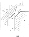
- FIG. 1 shows in an enlarged schematic partial view left and top a screw 10 according to the invention with a steeper cone portion 12 and flatter cone portion 14, and in parts the screw head 16 and the screw shaft 18, and right and down to the right side hole edge 20 of the through hole 22 of a component 24, for example a gear housing, wherein the steeper taper portion 12 of the screw and the transition region 28 between chamfer 30 and adjacent cylindrical hole edge 20 still have no contact.
- Angles are always given herein in relation to the vertical, be it a parallel to the hole axis or to the screw axis, which is only schematically illustrated in FIG FIG. 1 drawn on the left edge.
- the hole diameter of the unfetched hole section is 8.6 mm, that is, the screw has a clearance of about 0.3 mm on both sides.
- the chamfer angle ⁇ is 45 °
- the angle ⁇ of the steeper cone section 12 is about 25 °
- the angle ⁇ of the shallower cone section 14 about 45 °.
- the length of the steeper cone section measured along the cone is approximately 1.3 mm.
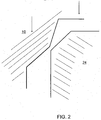
- FIG. 2 is a representation according to FIG. 1 , wherein the screw 10 has already approached the expected contact point by the first screwing, but still no contact has occurred.
- FIG. 3 is a representation according to FIG. 1 and 2 , wherein the screw 10 with its steeper cone section 12 the Transition region 28 of the Faste 30 has deformed to the cylindrical part of the hole in a small deformation portion 34, the screw head itself but still has no contact with its support surface.
- FIG. 4 is a representation according to FIG. 1 . 2 and 3 , wherein the screw head has been tightened now with its target torque, and the deformation portion 34 has become even larger, and wherein the required voltage between the screw head and its support surface (see dashed zone 36 top right) and the voltage between the component with the through hole and the to be connected to the second component is achieved with the mating thread.
- the cone portion 12 is sufficiently smooth and the surface of the chamfer 11 is sufficiently smooth, and the deformation occurs only when the contact between the cone portion and chamfer surface with a sufficiently large pressure
- the deformed surface forms according to the invention a sealing surface, technically causal is for the required sealing function. This can be done without the interposition of any kind of sealing ring. Nevertheless, a sealing ring, a washer, a snap ring or the like can be inserted between the screw head and the bearing surface without endangering the functioning of the principle according to the invention.
- the screw can also be used with more radial play, as long as the overlap is provided by the steeper cone section.
- the perpendicular line of the hole edge would be further offset to the right.
- the deformation range would thus be further shifted upwards, but the sealing surface would continue to exist, and the screw head would come to its desired edition and could produce reproducible stress on the components, because according to the invention, the cone length of the steeper cone section is significantly shortened compared to the prior art ,
- the inventive quality consists in the fact that the radial clearance, the overlapping area of the steeper cone section 12 and its cone angle are adapted such that the required tension between the head and its bearing surface can actually be generated without already too great a part of the tightening torque (usually a nominal size) is taken away for the screw to deform the material and thus for the production of the sealing surface.
- This can be achieved in principle with a steeper cone section 12, which is steep enough. To do this, give the above However, they do not represent an exhaustive selection.
- the angle of the flatter cone section can also be varied. Preferably, it is greater by an angle difference of 10 ° to 30 ° than that of the steep cone angle and preferably not significantly larger than the angle of the chamfer.
- transition between steep and shallow cone sections can also be rounded.
- cone contour does not necessarily have to be linear, but may be curved to some extent as long as the inventive principle is adhered to, as described above.
- the characteristic variables such as hole diameter, clearance, screw diameter, cone lengths, etc., can generally be adapted proportionally.
- a rounded chamfer is used, the inventive principle is also applicable. Decisive are then the angles of the chamfer surface in the expected contact area.
Landscapes
- Engineering & Computer Science (AREA)
- General Engineering & Computer Science (AREA)
- Mechanical Engineering (AREA)
- Bolts, Nuts, And Washers (AREA)
- Connection Of Plates (AREA)
Applications Claiming Priority (2)
| Application Number | Priority Date | Filing Date | Title |
|---|---|---|---|
| DE102010020078.6A DE102010020078B8 (de) | 2010-05-10 | 2010-05-10 | Gewindeschraube und Verfahren zur Herstellung einer Schraubverbindung |
| PCT/EP2011/002326 WO2011141163A1 (de) | 2010-05-10 | 2011-05-10 | Abdichtschraube mit verkürztem konusabschnitt |
Publications (2)
| Publication Number | Publication Date |
|---|---|
| EP2572081A1 EP2572081A1 (de) | 2013-03-27 |
| EP2572081B1 true EP2572081B1 (de) | 2016-08-03 |
Family
ID=44486991
Family Applications (1)
| Application Number | Title | Priority Date | Filing Date |
|---|---|---|---|
| EP11724534.0A Active EP2572081B1 (de) | 2010-05-10 | 2011-05-10 | Abdichtschraube mit verkürztem konusabschnitt |
Country Status (5)
| Country | Link |
|---|---|
| EP (1) | EP2572081B1 (pl) |
| DE (1) | DE102010020078B8 (pl) |
| ES (1) | ES2601780T3 (pl) |
| PL (1) | PL2572081T3 (pl) |
| WO (1) | WO2011141163A1 (pl) |
Families Citing this family (2)
| Publication number | Priority date | Publication date | Assignee | Title |
|---|---|---|---|---|
| CN104121058B (zh) * | 2014-07-10 | 2018-07-20 | 安徽江淮汽车集团股份有限公司 | 一种发动机润滑系统及其油道密封组件 |
| WO2017187383A1 (en) | 2016-04-29 | 2017-11-02 | Infastech Intellectual Properties Pte. Ltd. | Anti-vibration thread form |
Family Cites Families (5)
| Publication number | Priority date | Publication date | Assignee | Title |
|---|---|---|---|---|
| US2982166A (en) * | 1958-07-24 | 1961-05-02 | Robert W Hobbs | Fastener head the underlying surface of which has means to smooth the workpiece surface |
| US3680429A (en) * | 1970-03-17 | 1972-08-01 | Franklin S Briles | Self-gauging, interference fit rivet |
| US3849964A (en) * | 1973-08-15 | 1974-11-26 | F Briles | Corrosion blocking fastener |
| US5176215A (en) * | 1991-09-30 | 1993-01-05 | Chicago Rawhide Manufacturing Co. | Composite drain plug |
| DE10314948B4 (de) * | 2002-06-18 | 2005-11-17 | Hommel, Günter | Schraubverbindung |
-
2010
- 2010-05-10 DE DE102010020078.6A patent/DE102010020078B8/de not_active Expired - Fee Related
-
2011
- 2011-05-10 WO PCT/EP2011/002326 patent/WO2011141163A1/de not_active Ceased
- 2011-05-10 EP EP11724534.0A patent/EP2572081B1/de active Active
- 2011-05-10 ES ES11724534.0T patent/ES2601780T3/es active Active
- 2011-05-10 PL PL11724534T patent/PL2572081T3/pl unknown
Also Published As
| Publication number | Publication date |
|---|---|
| PL2572081T3 (pl) | 2017-02-28 |
| DE102010020078B8 (de) | 2015-09-03 |
| EP2572081A1 (de) | 2013-03-27 |
| WO2011141163A1 (de) | 2011-11-17 |
| DE102010020078B4 (de) | 2015-05-07 |
| ES2601780T3 (es) | 2017-02-16 |
| DE102010020078A1 (de) | 2011-11-10 |
Similar Documents
| Publication | Publication Date | Title |
|---|---|---|
| DE3325469C2 (de) | Verbindungsvorrichtung | |
| EP2857699A1 (de) | Gewindebuchse zum Einschrauben | |
| DE102015109278A1 (de) | Verbindungssystem, Klemmschraube, Verfahren zum Verbinden zweier Bauteile und Werkzeug zur Herstellung des Verbindungssystems | |
| EP2572081B1 (de) | Abdichtschraube mit verkürztem konusabschnitt | |
| WO2018113810A1 (de) | Schraubarbeitszylinder | |
| DE212017000096U1 (de) | Verschlusselement zum Verschließen und Abdichten innendruckbeanspruchter Bohrungen | |
| DE10325431A1 (de) | Verbindungsanordnung zweier Bauteile mit einem Blindniet und Verfahren zum Vernieten zweier Bauteile | |
| DE102007062830B4 (de) | Verfahren und Vorrichtung zum Herstellen eines Gewindes sowie Bauteil und Gerät | |
| DE102008020099B4 (de) | Durch mindestens eine Befestigungsschraube zu montierendes Bauteil | |
| EP1929163B1 (de) | Gewindebuchse, verfahren zum erneuern eines gewindes und werkzeug hierfür | |
| DE102011118587A1 (de) | Zweifach konische Schraubverbindung | |
| DE102016004962A1 (de) | Fügeelement zum Direktverschrauben von Bauteilen | |
| DE102004036518A1 (de) | Verdrehsichere Dichtkegelverbindung bei Einspritzleitungen zur Kraftstoffeinspritzung | |
| EP2876307B1 (de) | Arbeitszylinder und Verfahren zur Montage eines Arbeitszylinders | |
| EP3274192B1 (de) | Luftdruckmesseinrichtung für einen fahrzeugreifen und verfahren zur montage der luftdruckmesseinrichtung | |
| EP4538550B1 (de) | Additiv hergestelltes bauteil, bauteilverbund mit dem bauteil, herstellungsverfahren des bauteils und verbindungsverfahren zur herstellung des bauteilverbunds | |
| WO2008043773A1 (de) | Losdrehsicherungsanordnung für ein einschraubelement | |
| EP3265685A1 (de) | Befestigungselement und verfahren | |
| DE102014212095B4 (de) | Hohlschraube sowie Verbindungsanordnung und Hydraulikverbindung mit einer Hohlschraube | |
| DE102005031040A1 (de) | Gewindeeinsatz | |
| DE102024106805A1 (de) | Verbindungsvorrichtung | |
| EP4215766A1 (de) | Überstandslose blindnietmutter oder überstandsloser blindnietgewindebolzen | |
| DE102013017153A1 (de) | Gewindeelement für eine gewindeformende Schraube sowie Verbindungsanordnung einer gewindeformenden Schraube an einem solchen Gewindeelement | |
| DE102015202238A1 (de) | Verbindungsanordnung mit mindestens einem Niet sowie Verfahren zum Herstellen der Verbindungsanordnung | |
| WO2025119656A1 (de) | Befestigungsanordnung, bauteil mit der befestigungsanordnung, dazugehörige verbindungsstruktur sowie herstellungs- und verbindungsverfahren |
Legal Events
| Date | Code | Title | Description |
|---|---|---|---|
| PUAI | Public reference made under article 153(3) epc to a published international application that has entered the european phase |
Free format text: ORIGINAL CODE: 0009012 |
|
| 17P | Request for examination filed |
Effective date: 20121212 |
|
| AK | Designated contracting states |
Kind code of ref document: A1 Designated state(s): AL AT BE BG CH CY CZ DE DK EE ES FI FR GB GR HR HU IE IS IT LI LT LU LV MC MK MT NL NO PL PT RO RS SE SI SK SM TR |
|
| DAX | Request for extension of the european patent (deleted) | ||
| 17Q | First examination report despatched |
Effective date: 20150224 |
|
| GRAP | Despatch of communication of intention to grant a patent |
Free format text: ORIGINAL CODE: EPIDOSNIGR1 |
|
| INTG | Intention to grant announced |
Effective date: 20160212 |
|
| GRAS | Grant fee paid |
Free format text: ORIGINAL CODE: EPIDOSNIGR3 |
|
| GRAA | (expected) grant |
Free format text: ORIGINAL CODE: 0009210 |
|
| AK | Designated contracting states |
Kind code of ref document: B1 Designated state(s): AL AT BE BG CH CY CZ DE DK EE ES FI FR GB GR HR HU IE IS IT LI LT LU LV MC MK MT NL NO PL PT RO RS SE SI SK SM TR |
|
| RAP1 | Party data changed (applicant data changed or rights of an application transferred) |
Owner name: HOMMEL, GUENTER |
|
| REG | Reference to a national code |
Ref country code: GB Ref legal event code: FG4D Free format text: NOT ENGLISH |
|
| RIN1 | Information on inventor provided before grant (corrected) |
Inventor name: HOMMEL, GUENTER |
|
| REG | Reference to a national code |
Ref country code: CH Ref legal event code: EP Ref country code: AT Ref legal event code: REF Ref document number: 817482 Country of ref document: AT Kind code of ref document: T Effective date: 20160815 |
|
| REG | Reference to a national code |
Ref country code: IE Ref legal event code: FG4D Free format text: LANGUAGE OF EP DOCUMENT: GERMAN |
|
| REG | Reference to a national code |
Ref country code: DE Ref legal event code: R096 Ref document number: 502011010311 Country of ref document: DE |
|
| REG | Reference to a national code |
Ref country code: NL Ref legal event code: MP Effective date: 20160803 |
|
| REG | Reference to a national code |
Ref country code: LT Ref legal event code: MG4D |
|
| PG25 | Lapsed in a contracting state [announced via postgrant information from national office to epo] |
Ref country code: NO Free format text: LAPSE BECAUSE OF FAILURE TO SUBMIT A TRANSLATION OF THE DESCRIPTION OR TO PAY THE FEE WITHIN THE PRESCRIBED TIME-LIMIT Effective date: 20161103 Ref country code: NL Free format text: LAPSE BECAUSE OF FAILURE TO SUBMIT A TRANSLATION OF THE DESCRIPTION OR TO PAY THE FEE WITHIN THE PRESCRIBED TIME-LIMIT Effective date: 20160803 Ref country code: RS Free format text: LAPSE BECAUSE OF FAILURE TO SUBMIT A TRANSLATION OF THE DESCRIPTION OR TO PAY THE FEE WITHIN THE PRESCRIBED TIME-LIMIT Effective date: 20160803 Ref country code: FI Free format text: LAPSE BECAUSE OF FAILURE TO SUBMIT A TRANSLATION OF THE DESCRIPTION OR TO PAY THE FEE WITHIN THE PRESCRIBED TIME-LIMIT Effective date: 20160803 Ref country code: LT Free format text: LAPSE BECAUSE OF FAILURE TO SUBMIT A TRANSLATION OF THE DESCRIPTION OR TO PAY THE FEE WITHIN THE PRESCRIBED TIME-LIMIT Effective date: 20160803 Ref country code: IT Free format text: LAPSE BECAUSE OF FAILURE TO SUBMIT A TRANSLATION OF THE DESCRIPTION OR TO PAY THE FEE WITHIN THE PRESCRIBED TIME-LIMIT Effective date: 20160803 Ref country code: HR Free format text: LAPSE BECAUSE OF FAILURE TO SUBMIT A TRANSLATION OF THE DESCRIPTION OR TO PAY THE FEE WITHIN THE PRESCRIBED TIME-LIMIT Effective date: 20160803 Ref country code: IS Free format text: LAPSE BECAUSE OF FAILURE TO SUBMIT A TRANSLATION OF THE DESCRIPTION OR TO PAY THE FEE WITHIN THE PRESCRIBED TIME-LIMIT Effective date: 20161203 |
|
| REG | Reference to a national code |
Ref country code: ES Ref legal event code: FG2A Ref document number: 2601780 Country of ref document: ES Kind code of ref document: T3 Effective date: 20170216 |
|
| PG25 | Lapsed in a contracting state [announced via postgrant information from national office to epo] |
Ref country code: GR Free format text: LAPSE BECAUSE OF FAILURE TO SUBMIT A TRANSLATION OF THE DESCRIPTION OR TO PAY THE FEE WITHIN THE PRESCRIBED TIME-LIMIT Effective date: 20161104 Ref country code: SE Free format text: LAPSE BECAUSE OF FAILURE TO SUBMIT A TRANSLATION OF THE DESCRIPTION OR TO PAY THE FEE WITHIN THE PRESCRIBED TIME-LIMIT Effective date: 20160803 Ref country code: LV Free format text: LAPSE BECAUSE OF FAILURE TO SUBMIT A TRANSLATION OF THE DESCRIPTION OR TO PAY THE FEE WITHIN THE PRESCRIBED TIME-LIMIT Effective date: 20160803 Ref country code: PT Free format text: LAPSE BECAUSE OF FAILURE TO SUBMIT A TRANSLATION OF THE DESCRIPTION OR TO PAY THE FEE WITHIN THE PRESCRIBED TIME-LIMIT Effective date: 20161205 |
|
| PG25 | Lapsed in a contracting state [announced via postgrant information from national office to epo] |
Ref country code: EE Free format text: LAPSE BECAUSE OF FAILURE TO SUBMIT A TRANSLATION OF THE DESCRIPTION OR TO PAY THE FEE WITHIN THE PRESCRIBED TIME-LIMIT Effective date: 20160803 Ref country code: RO Free format text: LAPSE BECAUSE OF FAILURE TO SUBMIT A TRANSLATION OF THE DESCRIPTION OR TO PAY THE FEE WITHIN THE PRESCRIBED TIME-LIMIT Effective date: 20160803 |
|
| REG | Reference to a national code |
Ref country code: DE Ref legal event code: R097 Ref document number: 502011010311 Country of ref document: DE |
|
| PG25 | Lapsed in a contracting state [announced via postgrant information from national office to epo] |
Ref country code: BG Free format text: LAPSE BECAUSE OF FAILURE TO SUBMIT A TRANSLATION OF THE DESCRIPTION OR TO PAY THE FEE WITHIN THE PRESCRIBED TIME-LIMIT Effective date: 20161103 Ref country code: SM Free format text: LAPSE BECAUSE OF FAILURE TO SUBMIT A TRANSLATION OF THE DESCRIPTION OR TO PAY THE FEE WITHIN THE PRESCRIBED TIME-LIMIT Effective date: 20160803 Ref country code: DK Free format text: LAPSE BECAUSE OF FAILURE TO SUBMIT A TRANSLATION OF THE DESCRIPTION OR TO PAY THE FEE WITHIN THE PRESCRIBED TIME-LIMIT Effective date: 20160803 Ref country code: SK Free format text: LAPSE BECAUSE OF FAILURE TO SUBMIT A TRANSLATION OF THE DESCRIPTION OR TO PAY THE FEE WITHIN THE PRESCRIBED TIME-LIMIT Effective date: 20160803 |
|
| PLBE | No opposition filed within time limit |
Free format text: ORIGINAL CODE: 0009261 |
|
| STAA | Information on the status of an ep patent application or granted ep patent |
Free format text: STATUS: NO OPPOSITION FILED WITHIN TIME LIMIT |
|
| 26N | No opposition filed |
Effective date: 20170504 |
|
| PG25 | Lapsed in a contracting state [announced via postgrant information from national office to epo] |
Ref country code: SI Free format text: LAPSE BECAUSE OF FAILURE TO SUBMIT A TRANSLATION OF THE DESCRIPTION OR TO PAY THE FEE WITHIN THE PRESCRIBED TIME-LIMIT Effective date: 20160803 Ref country code: LU Free format text: LAPSE BECAUSE OF NON-PAYMENT OF DUE FEES Effective date: 20170531 |
|
| REG | Reference to a national code |
Ref country code: CH Ref legal event code: PL |
|
| GBPC | Gb: european patent ceased through non-payment of renewal fee |
Effective date: 20170510 |
|
| PG25 | Lapsed in a contracting state [announced via postgrant information from national office to epo] |
Ref country code: CZ Free format text: LAPSE BECAUSE OF NON-PAYMENT OF DUE FEES Effective date: 20170510 Ref country code: MC Free format text: LAPSE BECAUSE OF FAILURE TO SUBMIT A TRANSLATION OF THE DESCRIPTION OR TO PAY THE FEE WITHIN THE PRESCRIBED TIME-LIMIT Effective date: 20160803 |
|
| REG | Reference to a national code |
Ref country code: IE Ref legal event code: MM4A |
|
| PG25 | Lapsed in a contracting state [announced via postgrant information from national office to epo] |
Ref country code: CH Free format text: LAPSE BECAUSE OF NON-PAYMENT OF DUE FEES Effective date: 20170531 Ref country code: LI Free format text: LAPSE BECAUSE OF NON-PAYMENT OF DUE FEES Effective date: 20170531 |
|
| REG | Reference to a national code |
Ref country code: FR Ref legal event code: ST Effective date: 20180131 |
|
| PG25 | Lapsed in a contracting state [announced via postgrant information from national office to epo] |
Ref country code: LU Free format text: LAPSE BECAUSE OF NON-PAYMENT OF DUE FEES Effective date: 20170510 |
|
| REG | Reference to a national code |
Ref country code: BE Ref legal event code: MM Effective date: 20170531 |
|
| PG25 | Lapsed in a contracting state [announced via postgrant information from national office to epo] |
Ref country code: GB Free format text: LAPSE BECAUSE OF NON-PAYMENT OF DUE FEES Effective date: 20170510 Ref country code: IE Free format text: LAPSE BECAUSE OF NON-PAYMENT OF DUE FEES Effective date: 20170510 |
|
| PG25 | Lapsed in a contracting state [announced via postgrant information from national office to epo] |
Ref country code: FR Free format text: LAPSE BECAUSE OF NON-PAYMENT OF DUE FEES Effective date: 20170531 |
|
| REG | Reference to a national code |
Ref country code: ES Ref legal event code: FD2A Effective date: 20180627 |
|
| REG | Reference to a national code |
Ref country code: AT Ref legal event code: MM01 Ref document number: 817482 Country of ref document: AT Kind code of ref document: T Effective date: 20170510 |
|
| PG25 | Lapsed in a contracting state [announced via postgrant information from national office to epo] |
Ref country code: ES Free format text: LAPSE BECAUSE OF NON-PAYMENT OF DUE FEES Effective date: 20170511 |
|
| PG25 | Lapsed in a contracting state [announced via postgrant information from national office to epo] |
Ref country code: BE Free format text: LAPSE BECAUSE OF NON-PAYMENT OF DUE FEES Effective date: 20170531 Ref country code: AT Free format text: LAPSE BECAUSE OF NON-PAYMENT OF DUE FEES Effective date: 20170510 |
|
| PG25 | Lapsed in a contracting state [announced via postgrant information from national office to epo] |
Ref country code: MT Free format text: LAPSE BECAUSE OF FAILURE TO SUBMIT A TRANSLATION OF THE DESCRIPTION OR TO PAY THE FEE WITHIN THE PRESCRIBED TIME-LIMIT Effective date: 20160803 |
|
| PG25 | Lapsed in a contracting state [announced via postgrant information from national office to epo] |
Ref country code: PL Free format text: LAPSE BECAUSE OF NON-PAYMENT OF DUE FEES Effective date: 20170510 Ref country code: AL Free format text: LAPSE BECAUSE OF FAILURE TO SUBMIT A TRANSLATION OF THE DESCRIPTION OR TO PAY THE FEE WITHIN THE PRESCRIBED TIME-LIMIT Effective date: 20160803 |
|
| PG25 | Lapsed in a contracting state [announced via postgrant information from national office to epo] |
Ref country code: HU Free format text: LAPSE BECAUSE OF FAILURE TO SUBMIT A TRANSLATION OF THE DESCRIPTION OR TO PAY THE FEE WITHIN THE PRESCRIBED TIME-LIMIT; INVALID AB INITIO Effective date: 20110510 |
|
| PG25 | Lapsed in a contracting state [announced via postgrant information from national office to epo] |
Ref country code: CY Free format text: LAPSE BECAUSE OF NON-PAYMENT OF DUE FEES Effective date: 20160803 |
|
| PG25 | Lapsed in a contracting state [announced via postgrant information from national office to epo] |
Ref country code: MK Free format text: LAPSE BECAUSE OF FAILURE TO SUBMIT A TRANSLATION OF THE DESCRIPTION OR TO PAY THE FEE WITHIN THE PRESCRIBED TIME-LIMIT Effective date: 20160803 |
|
| PG25 | Lapsed in a contracting state [announced via postgrant information from national office to epo] |
Ref country code: TR Free format text: LAPSE BECAUSE OF FAILURE TO SUBMIT A TRANSLATION OF THE DESCRIPTION OR TO PAY THE FEE WITHIN THE PRESCRIBED TIME-LIMIT Effective date: 20160803 |
|
| PGFP | Annual fee paid to national office [announced via postgrant information from national office to epo] |
Ref country code: DE Payment date: 20250526 Year of fee payment: 15 |