EP2570257B1 - Aluminiumverbundwerkstoff mit AlMgSi-Kernlegierungsschicht - Google Patents
Aluminiumverbundwerkstoff mit AlMgSi-Kernlegierungsschicht Download PDFInfo
- Publication number
- EP2570257B1 EP2570257B1 EP11181524.7A EP11181524A EP2570257B1 EP 2570257 B1 EP2570257 B1 EP 2570257B1 EP 11181524 A EP11181524 A EP 11181524A EP 2570257 B1 EP2570257 B1 EP 2570257B1
- Authority
- EP
- European Patent Office
- Prior art keywords
- strip
- alloy
- rolling
- bending
- aluminium alloy
- Prior art date
- Legal status (The legal status is an assumption and is not a legal conclusion. Google has not performed a legal analysis and makes no representation as to the accuracy of the status listed.)
- Active
Links
Images


Classifications
-
- B—PERFORMING OPERATIONS; TRANSPORTING
- B32—LAYERED PRODUCTS
- B32B—LAYERED PRODUCTS, i.e. PRODUCTS BUILT-UP OF STRATA OF FLAT OR NON-FLAT, e.g. CELLULAR OR HONEYCOMB, FORM
- B32B15/00—Layered products comprising a layer of metal
- B32B15/01—Layered products comprising a layer of metal all layers being exclusively metallic
- B32B15/016—Layered products comprising a layer of metal all layers being exclusively metallic all layers being formed of aluminium or aluminium alloys
-
- B—PERFORMING OPERATIONS; TRANSPORTING
- B23—MACHINE TOOLS; METAL-WORKING NOT OTHERWISE PROVIDED FOR
- B23K—SOLDERING OR UNSOLDERING; WELDING; CLADDING OR PLATING BY SOLDERING OR WELDING; CUTTING BY APPLYING HEAT LOCALLY, e.g. FLAME CUTTING; WORKING BY LASER BEAM
- B23K20/00—Non-electric welding by applying impact or other pressure, with or without the application of heat, e.g. cladding or plating
- B23K20/04—Non-electric welding by applying impact or other pressure, with or without the application of heat, e.g. cladding or plating by means of a rolling mill
-
- B—PERFORMING OPERATIONS; TRANSPORTING
- B23—MACHINE TOOLS; METAL-WORKING NOT OTHERWISE PROVIDED FOR
- B23K—SOLDERING OR UNSOLDERING; WELDING; CLADDING OR PLATING BY SOLDERING OR WELDING; CUTTING BY APPLYING HEAT LOCALLY, e.g. FLAME CUTTING; WORKING BY LASER BEAM
- B23K20/00—Non-electric welding by applying impact or other pressure, with or without the application of heat, e.g. cladding or plating
- B23K20/22—Non-electric welding by applying impact or other pressure, with or without the application of heat, e.g. cladding or plating taking account of the properties of the materials to be welded
- B23K20/233—Non-electric welding by applying impact or other pressure, with or without the application of heat, e.g. cladding or plating taking account of the properties of the materials to be welded without ferrous layer
- B23K20/2336—Non-electric welding by applying impact or other pressure, with or without the application of heat, e.g. cladding or plating taking account of the properties of the materials to be welded without ferrous layer both layers being aluminium
-
- C—CHEMISTRY; METALLURGY
- C22—METALLURGY; FERROUS OR NON-FERROUS ALLOYS; TREATMENT OF ALLOYS OR NON-FERROUS METALS
- C22C—ALLOYS
- C22C21/00—Alloys based on aluminium
-
- C—CHEMISTRY; METALLURGY
- C22—METALLURGY; FERROUS OR NON-FERROUS ALLOYS; TREATMENT OF ALLOYS OR NON-FERROUS METALS
- C22C—ALLOYS
- C22C21/00—Alloys based on aluminium
- C22C21/06—Alloys based on aluminium with magnesium as the next major constituent
- C22C21/08—Alloys based on aluminium with magnesium as the next major constituent with silicon
-
- C—CHEMISTRY; METALLURGY
- C22—METALLURGY; FERROUS OR NON-FERROUS ALLOYS; TREATMENT OF ALLOYS OR NON-FERROUS METALS
- C22F—CHANGING THE PHYSICAL STRUCTURE OF NON-FERROUS METALS AND NON-FERROUS ALLOYS
- C22F1/00—Changing the physical structure of non-ferrous metals or alloys by heat treatment or by hot or cold working
- C22F1/04—Changing the physical structure of non-ferrous metals or alloys by heat treatment or by hot or cold working of aluminium or alloys based thereon
-
- C—CHEMISTRY; METALLURGY
- C22—METALLURGY; FERROUS OR NON-FERROUS ALLOYS; TREATMENT OF ALLOYS OR NON-FERROUS METALS
- C22F—CHANGING THE PHYSICAL STRUCTURE OF NON-FERROUS METALS AND NON-FERROUS ALLOYS
- C22F1/00—Changing the physical structure of non-ferrous metals or alloys by heat treatment or by hot or cold working
- C22F1/04—Changing the physical structure of non-ferrous metals or alloys by heat treatment or by hot or cold working of aluminium or alloys based thereon
- C22F1/05—Changing the physical structure of non-ferrous metals or alloys by heat treatment or by hot or cold working of aluminium or alloys based thereon of alloys of the Al-Si-Mg type, i.e. containing silicon and magnesium in approximately equal proportions
-
- Y—GENERAL TAGGING OF NEW TECHNOLOGICAL DEVELOPMENTS; GENERAL TAGGING OF CROSS-SECTIONAL TECHNOLOGIES SPANNING OVER SEVERAL SECTIONS OF THE IPC; TECHNICAL SUBJECTS COVERED BY FORMER USPC CROSS-REFERENCE ART COLLECTIONS [XRACs] AND DIGESTS
- Y10—TECHNICAL SUBJECTS COVERED BY FORMER USPC
- Y10T—TECHNICAL SUBJECTS COVERED BY FORMER US CLASSIFICATION
- Y10T428/00—Stock material or miscellaneous articles
- Y10T428/12—All metal or with adjacent metals
- Y10T428/12493—Composite; i.e., plural, adjacent, spatially distinct metal components [e.g., layers, joint, etc.]
- Y10T428/12736—Al-base component
- Y10T428/12764—Next to Al-base component
Definitions
- the invention relates to a strip consisting of an aluminum material for the production of components with high forming requirements and the use of metal sheets made from the strip according to the invention.
- sheets made of aluminum alloys are required which are not only characterized by particularly high strength values, but also have very good deformation behavior and enable high degrees of deformation.
- typical areas of application are the body and chassis parts.
- the materials In the case of visible, painted components, e.g. body panels that are visible on the outside, the materials must be reshaped in such a way that the surface is not impaired by defects such as flow patterns or roping after painting. This is particularly important, for example, for the use of aluminum alloy sheets for the production of engine hoods and other body components of a motor vehicle. However, it restricts the choice of material with regard to the aluminum alloy.
- AlMgSi alloys the main alloy components of which are magnesium and silicon, have relatively high strengths in condition T6 with good deformation behavior in condition T4 as well as excellent corrosion resistance.
- AlMgSi alloys are the alloy types AA6XXX, for example the alloy type AA6016, AA6014, AA6181, AA6060 and AA6111.
- Aluminum strips are usually produced from an AlMgSi alloy by casting a rolling bar, homogenizing the rolling bar, hot rolling the rolling bar and optionally cold rolling the hot strip.
- the slab is homogenized at a temperature of 380 to 580 ° C for more than an hour.
- the strips With a final solution annealing at a typical temperature of 500 ° C to 570 ° C with subsequent quenching and cold aging at around room temperature for at least three days, the strips can be delivered in T4 condition.
- the condition T6 is set after quenching by artificial aging at temperatures between 100 ° C and 220 ° C.
- the problem is that there are coarse Mg 2 Si precipitates in hot-rolled aluminum strips made of AlMgSi alloys, which are broken down and reduced in size in the subsequent cold rolling by high degrees of deformation.
- Hot strips of an AlMgSi alloy are usually produced in thicknesses of 3 mm to 12 mm and fed to cold rolling with a high degree of deformation. Since the temperature range in which the AlMgSi phases arise is passed through very slowly in conventional hot rolling, namely after the hot strip has been wound up, these phases develop very roughly.
- the temperature range for the formation of the phases mentioned above depends on the alloy. However, it is between 550 ° C and 230 ° C, i.e. in the range of hot rolling temperatures. It has been shown experimentally that these coarse phases in the hot strip have a negative effect on the elongation of the end product. This means that the forming behavior of aluminum strips made from AlMgSi alloys has not yet been fully exploited.
- the AlMgSi alloy strip has a temperature of a maximum of 130 ° C. immediately after the run-off from the last hot rolling pass and is wound up at this or a lower temperature.
- aluminum strips in condition T4 could be produced, which in condition T4 have an elongation at break of Aso of more than 30% or a uniform elongation A g of more than 25%.
- very high values for the uniform elongation A g and the elongation at break A 80 were also obtained in condition T6. In the areas of application mentioned, however, there is also the problem that strong bends and flanges are often required.
- a typical application that includes bends and flanges as well as high demands on formability is, for example, an inside door component of a motor vehicle.
- good results have already been achieved with previous AlMgSi alloy strips, but a further improvement in the bending behavior, especially taking into account the application mentioned, would be desirable.
- the US 2010/0279143 A1 relates to a two- or three-layer composite material with a core layer consisting of an AlMgSi alloy and a non-hardenable aluminum alloy layer.
- a core layer consisting of an AlMgSi alloy and a non-hardenable aluminum alloy layer.
- an AlMn-aluminum alloy as a core layer with at least one outer AlMgSi layer is also described in the cited US document. Indications of a particularly good deformation behavior of a combination of hardenable and non-hardenable aluminum alloy layers are not disclosed.
- the EP 1 852 250 A1 relates to a composite of a core layer and at least one hardenable cladding layer, both the core layer and the cladding layer consisting of an AA6000 alloy.
- the present invention is therefore based on the object of providing a strip consisting of an aluminum material for the production of components with high deformation requirements, which strip has an improved bending behavior.
- the above-mentioned object is achieved according to a first teaching with a band according to patent claim 1 and according to a second teaching with the use of a sheet made from a band according to patent claim 7.
- a strip made of an aluminum composite material with a core layer made of an AlMgSi alloy and at least one outer aluminum alloy layer arranged on one or both sides, which is made of a non-hardenable aluminum alloy exist, which have a lower tensile strength in the T4 state than the AlMgSi alloy lead to a significantly improved bending behavior in the T4 state than the uncoated AlMgSi alloy strip.
- the elongation at break A 80 of the outer aluminum alloy layers is also preferred
- the recrystallized state, i.e. also in the T4 state is greater than that of the core alloy layer made of an AlMgSi alloy in the T4 state.
- the force with which the bending punch bends the sample is measured and the bending process is terminated after a maximum has been exceeded and this maximum has fallen by 30N. Then the opening angle of the bent sample is measured.
- the bending behavior of the sample is usually measured transversely to the rolling direction in order to obtain reliable information about the bending behavior in the production of components with high deformation requirements.
- the samples made from a tape according to the invention allowed significantly smaller bending angles than the samples made from conventional, uncoated AlMgSi alloy tape and could therefore be better processed into components, for example an inside door part .
- a further improved deformation behavior and thus an expanded area of application can be provided in that the belt in state T4 has a uniform elongation of A g of more than 25%.
- the tape in condition T4 has a yield strength of Rp0.2 of 70-140 MPa and a tensile strength Rm of 170-220 MPa.
- the strength values mentioned ensure, on the one hand, sufficient rigidity in the manufacture of different components by forming, for example deep drawing or bending.
- the required forming forces are moderate due to the yield strength Rp0.2 of 70 - 140 MPa.
- the strip has an elongation at break A 80 transverse to the rolling direction of at least 27%, preferably at least 29%.
- the thickness of the outer aluminum alloy layers arranged on one or both sides is in each case 5% -15% of the final thickness of the tape.
- the outer aluminum alloy layers in order to achieve the maximum achievable bending angle, it is advantageous that the outer aluminum alloy layers have an average grain size of less than 50 ⁇ m, preferably less than 25 ⁇ m. It was found that the finer the structure of the outer aluminum alloy layer, the lower the bending angle that can be achieved.
- the AA8079 is a typical foil alloy like the aluminum alloys AA8011 and AA8006.
- the core layer of the tape according to the invention consists of an aluminum alloy of the type AA6014, AA6016, AA6060, AA6111 or AA6181. All alloy types AA6xxx have in common that they have particularly good deformation behavior characterized by high elongation values in condition T4 as well as high strengths or elongation limits in use condition T6, for example after artificial aging at 205 ° C / 30 min.
- magnesium contents of less than 0.25% by weight the strength of the aluminum strip, which is intended for structural applications, is too low; on the other hand, the formability deteriorates with magnesium contents above 0.6% by weight.
- silicon is essentially responsible for the hardenability of the aluminum alloy and thus also for the high strengths that can be achieved in the application, for example after a paint burn-in.
- Si contents of less than 1.0% by weight the hardenability of the aluminum strip is reduced, so that only reduced strengths can be provided in the application.
- Si contents of more than 1.5% by weight do not lead to any improvement in the hardening behavior.
- the Fe content should be limited to a maximum of 0.5% by weight in order to prevent coarse precipitations.
- Limiting the copper content to a maximum of 0.2% by weight leads primarily to improved corrosion resistance the aluminum alloy in the specific application.
- the manganese content of less than 0.2% by weight reduces the tendency to form coarser manganese precipitates.
- Chromium ensures a fine structure, but should be limited to 0.1% by weight in order to avoid coarse precipitations.
- the presence of manganese improved the weldability by reducing the tendency to crack or the sensitivity to quenching of the aluminum strip according to the invention.
- a reduction in the zinc content to a maximum of 0.1% by weight improves, in particular, the corrosion resistance of the aluminum alloy or of the finished sheet metal in the respective application.
- titanium ensures grain refinement during casting, but should be limited to a maximum of 0.1% by weight in order to ensure good castability of the aluminum alloy.
- the combination of precisely specified magnesium content with a reduced Si content compared to the first embodiment and a narrowly specified Fe content results in an aluminum alloy in which the formation of Mg 2 Si precipitates after hot rolling can be prevented particularly well with the method according to the invention, so that a sheet with an improved elongation and high yield strengths compared to conventionally produced sheets can be provided.
- the lower upper limits of the alloy components Cu, Mn and Cr additionally increase the effect of the method according to the invention. With regard to the effects of the upper limit of Zn and Ti, reference is made to the statements relating to the first embodiment of the aluminum alloy.
- All aluminum alloys shown are specifically adapted in their alloy components to different applications. As already stated, strips made of these aluminum alloys, which were produced using the method according to the invention, show particularly high uniform elongation values in condition T4 paired with a particularly pronounced increase in the yield strength, for example after artificial aging at 205 ° C / 30 min the aluminum strips subjected to heat treatment after the solution heat treatment in condition T4.
- the strip according to the invention can be produced using a method in which a rolling ingot is cast from a corresponding AlMgSi alloy, the rolling ingot is subjected to homogenization, at least one cladding layer is placed on one or both sides of the rolling ingot and the rolling ingot is placed together with the cladding layers placed thereon brought to hot rolling temperature, hot rolled, then optionally cold rolled to the final thickness and the finished rolled strip is solution annealed and quenched, the at least one cladding layer consisting of a corresponding, non-hardenable aluminum alloy, which has a lower tensile strength in the T4 state than the core layer made of an AlMgSi alloy possesses, the hot strip has a temperature of a maximum of 250 ° C immediately after the exit from the last hot rolling pass, preferably a temperature of a maximum of 230, particularly preferably a temperature of 230-200 ° C and the hot strip with this or a low temperature Geren temperature is wound.
- the strip can also be
- process-reliable cooling is achieved in that the hot strip is quenched to the winding temperature itself using at least one plate cooler and the hot rolling passes, which are acted upon with emulsion.
- a blank cooler consists of an arrangement of coolant or lubricant nozzles which spray a rolling emulsion onto the aluminum alloy strip.
- the blank cooler can be present in a hot rolling mill in order to cool rolled hot strips to the rolling temperature before hot rolling and in order to be able to achieve higher production speeds.
- hot rolling temperature of the hot strip is before the cooling process during hot rolling according to a further embodiment of the method, in particular before the penultimate one Hot rolling pass at at least 230 ° C, preferably above 400 ° C, particularly small Mg 2 Si precipitates can be produced in the quenched hot strip, since the majority of the alloy components magnesium and silicon are present in a dissolved state in the aluminum matrix at these temperatures.
- This advantageous condition of the hot strip is achieved especially at temperatures of 470 ° C - 490 ° C before the start of the cooling process, which preferably takes place within the last two rolling passes, and is virtually frozen by the quenching.
- the hot rolling temperature of the hot strip after the penultimate rolling pass is 290 ° C - 310 ° C. It has been shown that these temperatures both enable sufficient freezing of the precipitates and, on the other hand, the last rolling pass can be carried out without problems at the same time.
- the hot strip can have a temperature of 230 ° C.-200 ° C. at the outlet, so that a maximum process speed can be achieved during hot rolling without impairing the properties in condition T4 of the strip made from an aluminum composite material.
- the finished rolled aluminum strip is subjected to a heat treatment, the aluminum strip being heated to more than 100 ° C. after the solution heat treatment and quenching and then being wound up at a temperature of more than 55 ° C., preferably more than 85 ° C. and is outsourced.
- This embodiment of the method makes it possible to use a shorter heating phase after the cold aging process lower temperatures to set the state T6 in the strip or sheet in which the sheets or strips formed into components are used in the application. For this purpose, these rapidly hardening aluminum strips are only heated to temperatures of around 185 ° C for only 20 minutes in order to achieve the higher yield limit values in condition T6.
- the thickness of the finished hot strip is 3 mm-12 mm, preferably 5 mm-8 mm, so that conventional cold rolling stands can be used for cold rolling.
- the core layer of the tape according to the invention consists of an aluminum alloy of the alloy type AA6014, AA6016, AA6060, AA6111 or AA6181 and the outer aluminum alloy layers of an alloy type AA8xxx or AA1200.
- the outer aluminum alloy layers of different thickness and / or outer aluminum alloy layers consisting of different aluminum alloys of the type AA8xxx or AA1200 can be used.
- the combination of the alloy types mentioned in the aluminum alloy composite material results in excellent bending behavior and, at the same time, very high deformability in condition T4.
- the above-mentioned object is produced by using a sheet metal from a strip according to the invention as a component, chassis, structural part or sheet metal in motor vehicle, aircraft or rail vehicle construction, used in particular as a component, chassis part, outer or inner sheet in motor vehicle construction, preferably as a body component.
- the strip according to the invention made of an aluminum material is not only characterized by extraordinary forming properties, for example a very high uniform elongation A g transversely to the rolling direction, in addition, extreme bending angles can be realized with the strip according to the invention, which in the above-mentioned applications, occur especially with flanged folds. Furthermore, small radii in the component can also be better realized.
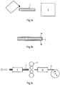
- Fig. 1 a) to e initially shows a schematic flow diagram of an embodiment of the method according to the invention for producing a strip according to the present invention with the steps a) producing and homogenizing the rolling bar, b) placing the cladding layers on the rolling bar, c) hot rolling or roll cladding of the rolling bar, d) Cold rolling and e) solution heat treatment with quenching.
- the rolling ingot produced in this way is homogenized at a homogenization temperature of about 550 ° C. for 8 hours in a furnace 2, so that the alloyed alloy components are distributed particularly homogeneously in the Rolling ingots are available, Fig. 1a ).
- Figure 1b it is now shown that aluminum alloy layers 1a and 1b have been placed on the rolling ingot 1 so that they can be welded to the rolling ingot during hot rolling.
- the aluminum alloy layers 1a and 1b consist, for example, of aluminum alloys of the type AA8079, which in the material state O, which corresponds to the state T4 after solution annealing, have a lower tensile strength Rm than that of the AlMgSi alloy layer, i.e. less than 180 MPa, for example.
- other aluminum alloys are also conceivable for the outer aluminum alloy layers, for example AA1200.
- the rolling ingot 1 with the applied aluminum alloy layers or cladding layers is used in the inventive, in Figure 1c ) shown embodiment is reversely hot rolled by a hot rolling stand 3, the rolling ingot 1 having a temperature of 400-550 ° C. during hot rolling.
- the hot strip 4 after leaving the hot rolling stand 3 and before the penultimate hot rolling pass, the hot strip 4 preferably has a temperature of at least 400.degree. C., preferably 470.degree. C.-490.degree. At this hot strip temperature, the hot strip 4 is preferably quenched using a plate cooler 5 and the work rolls of the hot rolling stand 3.
- the hot strip is cooled to a temperature of 290 ° C - 310 ° C before the last hot rolling pass, so that this is carried out reliably without any difficulties can be and the hot strip can be further cooled.
- the blank cooler 5 shown only schematically, sprays the hot strip with cooling roller emulsion and ensures accelerated cooling of the hot strip to the temperatures mentioned last.
- the work rolls of the hot rolling stand are also acted upon with emulsion and the hot strip 4 continues to cool during the last hot rolling pass.
- the hot strip 4 at the exit of the blank cooler 5 'in the present embodiment has a temperature of 230 ° C.-200 ° C. and is then wound up via the take-up reel 6 at this temperature.
- the hot strip 4 has a temperature of more than 135 ° C - 250 ° C, preferably 200 ° C - 330 ° C, directly at the outlet of the last hot rolling pass, or optionally in the last two hot rolling passes using the blank cooler and the work rolls of the hot rolling stand 3 is brought to the stated temperatures, the hot strip 4, despite the increased winding temperature, has a crystal structure which leads to very good uniform elongation values A g in the T4 state of more than 23%, preferably more than 25%. Despite the frozen state of the structure, the hot strip can be processed and wound up at the temperatures mentioned at a relatively high speed.
- the core alloy layer Since no coarse Mg 2 Si precipitates can form at the relatively low winding temperatures, the core alloy layer has a particularly advantageous crystal state and can therefore be particularly well cold-rolled using a cold rolling stand 9 and rewound on a winding reel 8, for example, Fig. 1d ).
- the resulting cold-rolled strip 11 is wound up. Then it is subjected to a solution heat treatment at a temperature of typically 500 ° C to 570 ° C and a quenching 10, Fig. 1e ). For this purpose, it is again unwound from the coil 12, solution annealed in a furnace 10 and then quenched and wound up again to form a coil 13.
- the aluminum strip can then be delivered after cold aging at room temperature in condition T4 with maximum formability.
- piece annealing can also be carried out as an alternative and the sheets can then be quenched.
- the tape according to the invention experiences a further increase in relation to the values of the yield point, so that particularly high strengths are achieved.
- Artificial aging can take place, for example, at 205 ° C. for 30 minutes.
- the strips made of an aluminum alloy composite material according to the exemplary embodiment shown here have, for example, a thickness of 0.5 mm to 4.5 mm after cold rolling. Strip thicknesses of 0.5 - 2 mm are usually used for body applications and strip thicknesses of 2.0 mm - 4.5 mm for chassis parts in motor vehicle construction.
- the improved uniform elongation values are a decisive advantage in the manufacture of the components, as the sheet metal is mostly formed and high strengths are still required in the T6 state of use of the end product.
- the improved flexibility of the strips according to the invention which, as already stated above, enable particularly small bending angles.
- the outer aluminum alloy layers have grain sizes of less than 50 ⁇ m, preferably less than 25 ⁇ m.
- a longitudinal section according to Barker through an embodiment of a tape 1 produced according to the invention is shown Fig. 2 in a greatly enlarged view.
- the outer aluminum alloy layer 1a which is formed here by an aluminum alloy of the AA8079 type, has a very much smaller grain size than the core alloy layer. In this exemplary embodiment, mean grain sizes of approximately 20 ⁇ m have been measured.
- Fig. 3 shows, in a perspective view, the test arrangement for carrying out the bending tests to determine the maximum bending angle.
- the tests are based on the specification of the Association of the German Automobile Industry (VDA) 238-100.
- the test arrangement consists of a bending punch 14, which in the present case has a punch radius of 0.4 mm.
- the sample 15 was previously cut out transversely to the rolling direction with a size of 270 mm ⁇ 60 mm. Then the sample 15 was stretched transversely to the rolling direction of 10% with a pre-stretching speed of 25 mm / min and a free clamping length of 150 mm. The sample 15 was then cut to a size of 60 ⁇ 60 mm and fed to the bending device.
- the bending punch 14 which as in Fig. 4 shown, parallel to the rolling direction runs so that the bending line 18 also runs parallel to the rolling direction, the sample now presses with a force F b between two rollers 16, 17 with a roller diameter of 30 mm, which are at a distance of twice the sample thickness (Table 2) or twice Sample thickness plus 0.5 mm (Table 3) are arranged. While the bending punch 14 bends the sample 15, the punch force F b is measured. If the punch force F b reaches a maximum and then drops by 30 N, the maximum achievable bending angle is reached. Then the sample 15 is removed from the bending device and the bending angle as in Fig. 5 shown measured.
- the Corel alloy was used as the core alloy layer, the alloy components of which are shown in Table 1.
- two different outer aluminum alloy layers Clad 1, Clad 2 were used, the composition of which is also shown in Table 1.
- Table 3 shows measurement results of exemplary embodiments according to the invention which were completely industrially produced, ie here the solution annealing step to achieve the state T4 was also implemented in a continuous belt furnace in the tests Erf5 to Erf8. All measurements shown in Table 3 were made on tapes with a thickness of 1.50 mm and thus on somewhat thinner tapes in comparison to the measurements in Table 2. The tapes Erf5 to Erf8 were also stored for 19 days at room temperature. For comparison, a typical aluminum alloy AA5182 used for automobile construction has been measured in Table 3. In the bending tests, in contrast to Table 2, a changed roller spacing was selected, which corresponded to twice the thickness of the sample to be measured plus 0.5 mm.
Landscapes
- Chemical & Material Sciences (AREA)
- Engineering & Computer Science (AREA)
- Mechanical Engineering (AREA)
- Materials Engineering (AREA)
- Metallurgy (AREA)
- Organic Chemistry (AREA)
- Physics & Mathematics (AREA)
- Thermal Sciences (AREA)
- Crystallography & Structural Chemistry (AREA)
- Metal Rolling (AREA)
- Laminated Bodies (AREA)
Description
- Die Erfindung betrifft ein Band bestehend aus einem Aluminiumwerkstoff zur Herstellung von Bauteilen mit hohen Umformanforderungen und die Verwendung von Blechen hergestellt aus dem erfindungsgemäßen Band.
- Vor allem im Kraftfahrzeugbau aber auch in anderen Anwendungsgebieten, beispielsweise dem Flugzeugbau oder Schienenfahrzeugbau werden Bleche aus Aluminiumlegierungen benötigt, welche sich nicht nur durch besonders hohe Festigkeitswerte auszeichnen, sondern gleichzeitig ein sehr gutes Umformverhalten aufweisen und hohe Umformgrade ermöglichen. Im Kraftfahrzeugbau sind typische Anwendungsgebiete die Karosserie und Fahrwerkteile. Bei sichtbaren, lackierten Bauteilen, beispielsweise außen sichtbaren Karosserieblechen, kommt hinzu, dass das Umformen der Werkstoffe so erfolgen muss, dass die Oberfläche nach der Lackierung nicht durch Fehler wie Fließfiguren oder Zugrilligkeit (Roping) beeinträchtigt ist. Dies ist beispielsweise für die Verwendung von Aluminiumlegierungsblechen zur Herstellung von Motorhauben und anderen Karosseriebauteilen eines Kraftfahrzeuges besonders wichtig. Es schränkt die Werkstoffwahl hinsichtlich der Aluminiumlegierung allerdings ein. Insbesondere AlMgSi-Legierungen, deren Hauptlegierungsbestandteile Magnesium und Silizium sind, weisen relativ hohe Festigkeiten auf im Zustand T6 bei gleichzeitig gutem Umformverhalten im Zustand T4 sowie hervorragender Korrosionsbeständigkeit. AlMgSi-Legierungen sind die Legierungstypen AA6XXX, beispielsweise der Legierungstyp AA6016, AA6014, AA6181, AA6060 und AA6111.
- Üblicherweise werden Aluminiumbänder aus einer AlMgSi-Legierung durch Gießen eines Walzbarrens, Homogenisieren des Walzbarrens, Warmwalzen des Walzbarrens und ein optionales Kaltwalzen des Warmbandes hergestellt. Die Homogenisierung des Walzbarrens erfolgt bei einer Temperatur von 380 bis 580 °C für mehr als eine Stunde. Durch ein abschließendes Lösuńgsglühen bei einer typischen Temperatur von 500 °C bis 570 °C mit nachfolgendem Abschrecken und Kaltauslagern etwa bei Raumtemperatur für mindestens drei Tage können die Bänder im Zustand T4 ausgeliefert werden. Der Zustand T6 wird nach dem Abschrecken durch eine Warmauslagerung bei Temperaturen zwischen 100 °C und 220 °C eingestellt.
- Problematisch ist, dass in warmgewalzten Aluminiumbändern aus AlMgSi-Legierungen grobe Mg2Si-Ausscheidungen vorliegen, welche im anschließenden Kaltwalzen durch hohe Umformgrade gebrochen und verkleinert werden. Warmbänder einer AlMgSi-Legierung werden in der Regel in Dicken von 3 mm bis 12 mm hergestellt und einem Kaltwalzen mit hohen Umformgraden zugeführt. Da der Temperaturbereich, in dem die AlMgSi-Phasen entstehen, beim konventionellen Warmwalzen sehr langsam durchlaufen wird, nämlich nach dem Aufwickeln des Warmbandes, bilden sich diese Phasen sehr grob aus. Der Temperaturbereich zur Bildung der obengenannten Phasen ist legierungsabhängig. Er liegt aber zwischen 550°C und 230°C also im Bereich der Warmwalztemperaturen. Es konnte experimentell nachgewiesen werden, dass diese groben Phasen im Warmband die Dehnung des Endprodukts negativ beeinflussen. Das bedeutet, dass das Umformverhalten von Aluminiumbändern aus AlMgSi-Legierungen bisher nicht vollständig ausgeschöpft werden konnte.
- In der veröffentlichten europäischen Patentanmeldung
EP 2 270 249 A1 , welche auf die Anmelderin zurückgeht, wurde vorgeschlagen, dass das AlMgSi-Legierungsband unmittelbar nach dem Ablauf aus dem letzten Warmwalzstich eine Temperatur von maximal 130°C aufweist und mit dieser oder einer geringeren Temperatur aufgewickelt wird. Durch das Abschrecken des Warmbandes mit diesem Verfahren konnten Aluminiumbänder im Zustand T4 hergestellt werden, welche im Zustand T4 eine Bruchdehnung von Aso von mehr als 30% oder eine Gleichmaßdehnung Ag von mehr als 25% aufweisen. Darüber hinaus ergaben sich auch im Zustand T6 sehr hohe Werte für die Gleichmaßdehnung Ag und die Bruchdehnung A80. In den genannten Anwendungsgebieten besteht jedoch zusätzlich die Problematik, dass häufig starke Biegungen und Bördelungen benötigt werden. Eine typische Anwendung, die Biegungen und Bördelungen sowie hohe Anforderungen an die Umformbarkeit umfasst, ist beispielsweise ein Tür-Innen-Bauteil eines Kraftfahrzeugs. Im Biegeversuch konnten mit bisherigen AlMgSi-Legierungsbändern zwar schon gute Ergebnisse erzielt werden, eine weitere Verbesserung des Biegeverhaltens, insbesondere unter Berücksichtigung der genannten Anwendung wäre jedoch wünschenswert. - In der
EP 2 156 945 A1 wird zur Verbesserung der Falzbarkeit von Blechen, welche eine hohe Festigkeit aufweisen, vorgeschlagen, einen Verbund aus einer Kernschicht aus einer AA 6XXX Legierung und mindestens einer Plattierschicht, welche ebenfalls aus einer AA 6xxx Legierung besteht, vorzusehen. - Die
US 2010/0279143 A1 betrifft einen zwei- oder dreischichtigen Verbundwerkstoff mit einer Kernschicht bestehend aus einer AlMgSi-Legierung und einer nichtaushärtbaren Aluminiumlegierungschicht. Darüber hinaus wird in der genannten US-Schrift auch die Kombination aus einer AlMn-aluminiumlegierung als Kernschicht mit mindestens einer äußeren AlMgSi-Schicht beschrieben. Hinweise auf ein besonders gutes Umformverhalten einer Kombination aus aushärtbaren und nicht aushärtbaren Aluminiumlegierungsschichten werden nicht offenbart. - Die
EP 1 852 250 A1 betrifft einen Verbund aus einer Kernschicht und mindestens einer aushärtbaren Plattierschicht, wobei sowohl die Kernschicht als auch die Plattierschicht aus einer AA6000-Legierung besteht. - Hiervon ausgehend liegt der vorliegenden Erfindung daher die Aufgabe zugrunde, ein Band bestehend aus einem Aluminiumwerkstoff zur Herstellung von Bauteilen mit hohen Umformanforderungen bereitzustellen, welches ein verbessertes Biegeverhalten aufweist.
- Erfindungsgemäß wird die oben aufgezeigte Aufgabe gemäß einer ersten Lehre mit einem Band nach Patentanspruch 1 und gemäß einer zweiten Lehre mit der Verwendung eines Blechs hergestellt aus einem Band nach Patentanspruch 7 gelöst.
- Überraschenderweise wurde festgestellt, dass ein Band aus einem Aluminiumverbundwerkstoff mit einer Kernschicht aus einer AlMgSi-Legierung und mindestens einer ein- oder beidseitig angeordneten äußeren Aluminiumlegierungsschicht, welche aus einer nicht aushärtbaren Aluminiumlegierung bestehen, die eine geringere Zugfestigkeit im Zustand T4 als die AlMgSi-Legierung aufweisen zu einem deutlich verbesserten Biegeverhalten im Zustand T4 führen, als das unbeschichtete AlMgSi-Legierungsband. Bevorzugt ist auch die Bruchdehnung A80 der äußeren Aluminiumlegierungsschichten im
rekristallisierten Zustand, also auch im Zustand T4, größer als die der Kernlegierungsschicht aus einer AlMgSi-Legierung im Zustand T4. Bei starken Biegungen des Bandes zeigt sich eine deutlich glattere und saubere Biegekante bis in den maximal erreichbaren Biegewinkel hinein. Bisher hatte man an Biegungen, wie sie beispielsweise bei Bördelungen benötigt werden, das Problem, dass Risse oder Rauigkeiten im Bereich der Biegekante auftraten. Es wird davon ausgegangen, dass die weicheren äußeren Aluminiumlegierungsschichten ein "Ausschmieren" von Unebenheiten beim Biegen ermöglichen, so dass erheblich kleinere Biegewinkel bei nahezu identischen mechanischen Eigenschaften gegenüber einem unbeschichteten Band aus einer AlMgSi-Legierung erreicht werden. Für die äußeren Schichten kommen Folienlegierungen vom Typ AA8xxx, also AA8011, AA8006, AA8079 etc. aber auch andere niedrig legierte Aluminiumlegierungen vom Typ AA1200 in Frage, die im Zustand O, also beisielweise nach einem Lösungsglühen und Abschrecken, Zugfestigkeiten im rekristallisierten Zustand von weniger als 180 MPa aufweisen. Die im Biegeversuch erreichten Biegewinkel quer zur Walzrichtung von weniger als 40° ermöglichen ein besseres Bördel- und Biegeverhalten des hergestellten Bandes im Einsatz, beispielsweise im Kraftfahrzeugbau. - Um den maximal erreichbaren Biegewinkel zu ermitteln, wurden anerkannte Verfahren aus der Automobilindustrie verwendet. Für den Biegeversuch sind zunächst Proben in der Größe von 270 mm x 60 mm quer zur Walzrichtung aus dem Band geschnitten und einer Vordehnung senkrecht zur Biegelinie, d.h. senkrecht zur Walzrichtung unterzogen worden. Die Vordehnung beträgt 10%. Anschließend wird über einen Biegestempel die Probe zwischen zwei Rollen mit einem Durchmesser von 30 mm gebogen. Der Rollenabstand beträgt dabei das Zweifache der Banddicke (Tabelle 2), bevorzugt auch das Zweifache der Banddicke der Probe zuzüglich 0,5 mm (Tabelle 3). Beim Biegen der Probe durch den Biegestempel, welcher einen Stempelradius von 0,4 mm aufweist, wird die Kraft, mit welcher der Biegestempel die Probe biegt, gemessen und nach Überschreiten eines Maximums und eines Absinkens von diesem Maximum um 30 N der Biegevorgang beendet. Anschließend wird der Öffnungswinkel der gebogenen Probe gemessen. Das Biegeverhalten der Probe wird in der Regel quer zur Walzrichtung vermessen, um eine belastbare Aussage bezüglich des Biegeverhaltens bei der Herstellung von Bauteilen mit hohen Umformungsanforderungen zu erhalten. Wie bereits ausgeführt, zeigte sich überraschenderweise, dass die aus einem erfindungsgemäßen Band hergestellten Proben deutlich geringere Biegewinkel zuließen, als die aus konventionellen, unbeschichteten AlMgSi-Legierungsband hergestellten Proben und insofern besser zu Bauteilen, beispielsweise zu einem Tür-Innen-Teil, verarbeitet werden können.
- Gemäß einer ersten Ausgestaltung des erfindungsgemäßen Bandes kann ein weiter verbessertes Umformverhalten und damit ein erweiterter Anwendungsbereich dadurch bereit gestellt werden, dass das Band im Zustand T4 eine Gleichmaßdehnung von Ag von mehr als 25% aufweist.
- Neben den guten Gleichmaßdehnungseigenschaften des erfindungsgemäßen Bandes ist für die Weiterverarbeitung zu einem fertigen, auswertbaren Produkt vorteilhaft, wenn das Band im Zustand T4 eine Dehngrenze von Rp0,2 von 70 - 140 MPa und eine Zugfestigkeit Rm von 170 - 220 MPa aufweist. Die genannten Festigkeitswerte gewährleisten einerseits eine ausreichende Steifigkeit bei der Herstellung von unterschiedlichen Bauteilen durch Umformungen, beispielsweise Tiefziehen oder Biegen. Darüber hinaus sind die benötigten Umformkräfte aufgrund der Dehngrenze Rp0,2 von 70 - 140 MPa moderat.
- Noch größere Umformgrade können gemäß einer nächsten Ausführungsform des erfindungsgemäßen Bandes dadurch erreicht werden, dass das Band eine Bruchdehnung A80 quer zur Walzrichtung von mindestens 27%, vorzugsweise mindestens 29% aufweist.
- Gemäß einer weiteren vorteilhaften Ausgestaltung des erfindungsgemäßen Bandes beträgt die Dicke der ein- oder beidseitig angeordneten, äußeren Aluminiumlegierungsschichten jeweils 5% - 15% der Enddicke des Bandes. Hierdurch wird gewährleistet, dass im Wesentlichen die Umformeigenschaften und die Festigkeitseigenschaften der Kernlegierungsschicht aus einer AlMgSi-Legierung das Herstellverfahren und die späteren Produkteigenschaften bestimmen, so dass die Vorzüge der aushärtbaren Kernlegierung zur Geltung kommen.
- Darüber hinaus ist es gemäß einer weiteren Ausführungsform des erfindungsgemäßen Bandes für das Erzielen der maximal erreichbaren Biegewinkel vorteilhaft, dass die äußeren Aluminiumlegierungsschichten eine mittlere Korngröße von weniger als 50 µm, vorzugsweise weniger als 25 µm aufweisen. Es konnte festgestellt werden, dass je feinkörniger die äußere Aluminiumlegierungsschicht aufgebaut ist, die erreichbaren Biegewinkel verringert werden konnten.
- Besteht gemäß einem weiteren Ausführungsbeispiel die mindestens eine äußere Aluminiumlegierungsschicht aus einer Aluminiumlegierung vom Typ AA8079 kann beispielsweise eine besonders feinkörnige Aluminiumlegierungsschicht bereitgestellt werden, welche das Biegeverhalten optimal beeinflusst. Die Aluminiumlegierung AA8079 weist die folgenden Legierungsbestandteile in Gew.-% auf:
- 0,05 % ≤ Si ≤ 0,30 %,
- 0,7 % ≤ Fe ≤ 1,3 %,
- Cu ≤ 0,05 %,
- Zn ≤ 0,10 %,
- Rest Al sowie unvermeidbare Verunreinigungen einzeln maximal 0,05 und in Summe maximal 0,15 %. Die AA8079 ist eine typische Folienlegierung wie auch die Aluminiumlegierungen AA8011 und AA8006.
- Die Kernschicht des erfindungsgemäßen Bandes besteht aus einer Aluminiumlegierung vom Typ AA6014, AA6016, AA6060, AA6111 oder AA6181. Allen Legierungstypen AA6xxx ist gemein, dass sie ein besonders gutes Umformverhalten gekennzeichnet durch hohe Dehnungswerte im Zustand T4 sowie hohe Festigkeiten bzw. Dehngrenzen im Einsatzzustand T6, beispielsweise nach einem Warmauslagern bei 205°C/30 min. aufweisen.
- Eine Aluminiumlegierung vom Typ AA6016 weist folgende Legierungsbestandteile in Gewichtsprozent auf:
- 0,25 % ≤ Mg ≤ 0,6 %,
- 1,0 % ≤ Si ≤ 1,5 %,
- Fe ≤ 0,5 %,
- Cu ≤ 0,2 %,
- Mn ≤ 0,2 %,
- Cr ≤ 0,1 %,
- Zn ≤ 0,1 %,
- Ti ≤ 0,1 %
- Bei Magnesiumgehalten von weniger als 0,25 Gew.-% ist die Festigkeit des Aluminiumbandes, welches für Strukturanwendungen vorgesehen ist zu gering, andererseits verschlechtert sich die Umformbarkeit bei Magnesiumgehalten oberhalb von 0,6 Gew.-%. Silizium ist im Zusammenspiel mit Magnesium im Wesentlichen für die Aushärtbarkeit der Aluminiumlegierung verantwortlich und somit auch für die hohen Festigkeiten, welche im Anwendungsfall beispielsweise nach einem Lackiereinbrennen erzielt werden können. Bei Si-Gehalten von weniger als 1,0 Gew.-% ist die Aushärtbarkeit des Aluminiumbandes verringert, so dass im Anwendungsfall nur verringerte Festigkeiten bereitgestellt werden können. Si-Gehalte von mehr als 1,5 Gew.-% führen zu keiner Verbesserung des Aushärteverhaltens. Der Fe-Anteil sollte auf maximal 0,5 Gew-% begrenzt werden, um grobe Ausscheidungen zu verhindern. Eine Beschränkung des Kupfergehalts auf maximal 0,2 Gew.-% führt vor allem zu einer verbesserten Korrosionsbeständigkeit der Aluminiumlegierung in der spezifischenAnwendung. Der Mangangehalt von weniger als 0,2 Gew.-% verringert die Tendenz zur Bildung von gröberen Mangangausscheidungen. Chrom sorgt zwar für ein feines Gefüge, ist aber auf 0,1 Gew.-% zu beschränken, um ebenfalls grobe Ausscheidungen zu vermeiden. Das Vorhandensein von Mangan verbesserte dagegen die Schweißbarkeit durch Verringerung der Rissneigung beziehungsweise Abschreckempfindlichkeit des erfindungsgemäßen Aluminiumbandes. Eine Reduzierung des Zink-Gehaltes auf maximal 0,1 Gew.-% verbessert insbesondere die Korrosionsbeständigkeit der Aluminiumlegierung bzw. des fertigen Blechs in der jeweiligen Anwendung. Dagegen sorgt Titan für eine Kornfeinung während des Gießens, sollte aber auf maximal 0,1 Gew.-% beschränkt werden, um eine gute Gießbarkeit der Aluminiumlegierung zu gewährleisten.
- Eine Aluminiumlegierung vom Typ AA6060 weist folgende Legierungsbestandteile in Gewichtsprozent auf:
- 0,35 % ≤ Mg ≤ 0,6 %,
- 0,3 % ≤ Si ≤ 0,6 %,
- 0,1 % ≤ Fe ≤ 0,3 %
- Cu ≤ 0,1 %,
- Mn ≤ 0,1 %,
- Cr ≤ 0,05 %,
- Zn ≤ 0,10 %,
- Ti ≤ 0,1 % und
- Die Kombination aus genau vorgegebenem Magnesiumgehalt mit einem im Vergleich zur ersten Ausführungsform reduzierten Si-Gehalt und eng spezifiziertem Fe-Gehalt ergibt eine Aluminiumlegierung, bei welcher besonders gut die Bildung Mg2Si Ausscheidungen nach dem Warmwalzen mit dem erfindungsgemäßen Verfahren verhindert werden kann, so dass ein Blech mit einer verbesserten Dehnung und hohen Dehngrenzen im Vergleich zu konventionell hergestellten Blechen bereitgestellt werden kann. Die geringeren Obergrenzen der Legierungsbestandteile Cu, Mn und Cr verstärken den Effekt des erfindungsgemäßen Verfahrens zusätzlich. Hinsichtlich der Auswirkungen der Obergrenze von Zn und Ti wird auf die Ausführungen zur ersten Ausführungsform der Aluminiumlegierung verwiesen.
- Eine Aluminiumlegierung vom Typ AA6014 weist folgende Legierungsbestandteile in Gewichtsprozent auf:
- 0,4 % ≤ Mg ≤ 0,8 %,
- 0,3 % ≤ Si ≤ 0,6 %,
- Fe ≤ 0,35 %
- Cu ≤ 0,25 %,
- 0,05 % ≤ Mn ≤ 0,20 %,
- Cr ≤ 0,20 %,
- Zn ≤ 0,10 %,
- 0,05 % ≤ V ≤ 0,20 %,
Ti ≤ 0,1 % und - Eine Aluminiumlegierung vom Typ AA6181 weist folgende Legierungsbestandteile in Gewichtsprozent auf:
- 0,6 % ≤ Mg ≤ 1,0 %,
- 0,8 % ≤ Si ≤ 1,2 %,
- Fe ≤ 0,45 %
- Cu ≤ 0,10 %,
- Mn ≤ 0,15 %,
- Cr ≤ 0,10 %,
- Zn ≤ 0,20 %,
- Ti ≤ 0,1 % und
- Eine Aluminiumlegierung vom Typ AA6111 weist folgende Legierungsbestandteile in Gewichtsprozent auf:
- 0,5 % ≤ Mg ≤ 1,0 %,
- 0,7 % ≤ Si ≤ 1,1 %,
Fe ≤ 0,40 % - 0,50 % ≤ Cu ≤ 0,90 %,
- 0,15 % ≤ Mn ≤ 0,45 %,
- Cr ≤ 0,10 %,
- Zn ≤ 0,15 %,
- Ti ≤ 0,1 % und
- Alle aufgezeigten Aluminiumlegierungen sind spezifisch in ihren Legierungsbestandteilen auf unterschiedliche Anwendungen angepasst. Wie bereits ausgeführt, zeigen Bänder aus diese Aluminiumlegierungen, welche unter Verwendung des erfindungsgemäßen Verfahrens hergestellt wurden, besonders hohe Gleichmaßdehnungswerte im Zustand T4 gepaart mit einer besonders ausgeprägten Steigerung der Dehngrenze beispielsweise nach einem Warmauslagern bei 205 °C / 30 Min.. Dies gilt auch für die nach dem Lösungsglühen einer Wärmebehandlung unterzogenen Aluminiumbändern im Zustand T4.
- Das erfindungsgemäße Band kann mit einem Verfahren hergestellt werden, bei welchem ein Walzbarren aus einer entsprechenden AlMgSi-Legierung gegossen wird, der Walzbarren einer Homogenisierung unterzogen wird, ein- oder beidseitig auf den Walzbarren mindestens eine Plattierschicht aufgelegt wird und der Walzbarren gemeinsam mit den aufgelegten Plattierschichten auf Warmwalztemperatur gebracht, warmgewalzt, anschließend optional auf Enddicke kaltgewalzt und das fertig gewalzte Band lösungsgelüht und abgeschreckt wird, wobei die mindestens eine Plattierschicht aus einer entsprechenden, nicht aushärtbaren Aluminiumlegierung besteht, welche eine geringere Zugfestigkeit im Zustand T4 als die Kernschicht aus einer AlMgSi-Legierung besitzt, das Warmband unmittelbar nach dem Auslauf aus dem letzten Warmwalzstich eine Temperatur von maximal 250°C vorzugsweise eine Temperatur von maximal 230, besonders bevorzugt eine Temperatur von 230 - 200°C aufweist und das Warmband mit dieser oder einer geringeren Temperatur aufgewickelt wird. Prinzipiell kann das Band auch auf eine Temperatur von weniger als 200°C abgekühlt werden. Darüber hinaus ist vorstellbar, das Band aus einem Aluminiumverbundwerkstoff auch durch Anwendung eines simultanen Gießens herzustellen und anschließend warmzuwalzen.
- Es hat sich gezeigt, dass das Abschrecken des Warmbandes auch nach einem Walzplattieren, bei welchem Warmwalztemperaturen verwendet werden, zu einem besonders günstigen Gefüge des Warmbandes führt, welches besonders hohe Bruchdehnungswerte A80, Gleichmaßdehnungswerte Ag und zusätzlich aufgrund der äußeren Aluminiumlegierungsschichten ein verbessertes Biegeverhalten aufweist. Der Temperaturkorridor des Warmbandes unmittelbar nach dem Auslauf aus dem letzten Warmwalzstich, welcher auch von 135°C - 250°C erstreckt, ließ auch bei der Produktion von Aluminiumverbundwerkstoffen eine hohe Produktionsrate bei gleichzeitig guter Prozesssicherheit zu.
- Gemäß einer weiteren Ausgestaltung des Verfahrens wird ein prozesssicheres Abkühlen dadurch erzielt, dass das Warmband unter Verwendung von mindestens einem Platinenkühler und der mit Emulsion beaufschlagten Warmwalzstiche selbst auf Aufwickeltemperatur abgeschreckt wird. Ein Platinenkühler besteht aus einer Anordnung von Kühl- bzw. Schmiermitteldüsen, welche eine Walzemulsion auf das Aluminiumlegierungsband sprühen. Der Platinenkühler kann in einem Warmwalzwerk vorhanden sein, um gewalzte Warmbänder vor dem Warmwalzen auf Walztemperatur zu kühlen und um höhere Produktionsgeschwindigkeiten erreichen zu können.
- Liegt die Warmwalztemperatur des Warmbandes vor dem Abkühlprozess während des Warmwalzens gemäß einer weiteren Ausgestaltung des Verfahrens, insbesondere vor dem vorletzten Warmwalzstich bei mindestens 230°C, vorzugsweise über 400°C, können besonders kleine Mg2Si-Ausscheidungen im abgeschreckten Warmband erzeugt werden, da der größte Teil der Legierungsbestandteile Magnesium und Silizium bei diesen Temperaturen in gelöstem Zustand in der Aluminiummatrix vorliegen. Dieser vorteilhafte Zustand des Warmbandes wird besonders bei Temperaturen von 470°C - 490°C vor dem Start des Abkühlprozesses, welcher vorzugsweise innerhalb der letzten beiden Walzstiche stattfindet, erreicht und durch das Abschrecken quasi eingefroren.
- Gemäß einer weiteren Ausgestaltung des Verfahrens beträgt die Warmwalztemperatur des Warmbandes nach dem vorletzten Walzstich 290°C - 310°C. Es hat sich gezeigt, dass diese Temperaturen sowohl eine ausreichendes Einfrieren der Ausscheidungen ermöglicht und andererseits gleichzeitig der letzte Walzstich ohne Probleme durchgeführt werden kann. Am Auslauf kann das Warmband gemäß einer nächsten vorteilhaften Ausführungsform eine Temperatur von 230°C - 200°C aufweisen, so dass eine maximale Prozessgeschwindigkeit beim Warmwalzen realisiert werden kann, ohne die Eigenschaften im Zustand T4 des hergestellten Band aus einem Aluminiumverbundwerkstoff zu verschlechtern.
- Gemäß einer weiteren Ausgestaltung des Verfahrens wird das fertig gewalzte Aluminiumband einer Wärmebehandlung unterzogen, wobei das Aluminiumband nach dem Lösungsglühen und Abschrecken auf mehr als 100 °C erwärmt wird und anschließend mit einer Temperatur von mehr als 55 °C, vorzugsweise mehr als 85 °C aufgewickelt und ausgelagert wird. Diese Ausführungsform des Verfahrens ermöglicht es nach der Kaltauslagerung durch eine kürzere Erwärmungsphase mit niedrigeren Temperaturen den Zustand T6 in dem Band oder Blech einzustellen, in welchem die zu Bauteilen umgeformten Bleche oder Bänder in der Anwendung eingesetzt werden. Diese schnell aushärtenden Aluminiumbänder werden hierzu lediglich auf Temperaturen von etwa 185 °C für lediglich 20 Min. erwärmt, um die höheren Streckgrenzwerte im Zustand T6 zu erreichen.
- Die Dicke des fertigen Warmbandes beträgt 3 mm - 12 mm, vorzugsweise 5 mm - 8 mm, so dass übliche Kaltwalzgerüste für das Kaltwalzen verwendet werden können.
- Bei dem Verfahren zur Herstellung eines erfindungsgemäßen Bandes besteht die Kernschicht des erfindungsgemäßen Bandes aus einer Aluminiumlegierung vom Legierungstyp AA6014, AA6016, AA6060, AA6111 oder AA6181 und die äußeren Aluminiumlegierungsschichten aus einem Legierungstyp AA8xxx oder AA1200. Selbstverständlich sind sowohl unterschiedlich dicke äußere Aluminiumlegierungsschichten und/oder aus unterschiedlichen Aluminiumlegierungen vom Typ AA8xxx oder AA1200 bestehende äußere Aluminiumlegierungsschichten einsetzbar. Darüber hinaus ergibt die Kombination der genannten Legierungstypen beim Aluminiumlegierungsverbundwerkstoff ein hervorragendes Biegeverhalten bei gleichzeitig sehr hohem Umformvermögen im Zustand T4.
- Schließlich wird gemäß einer zweiten Lehre der vorliegenden Erfindung die oben aufgezeigte Aufgabe durch die Verwendung eines Blechs hergestellt aus einem erfindungsgemäßen Band als Bauteil, Fahrwerks-, Strukturteil oder Blech im Kraftfahrzeug-, Flugzeug- oder Schienenfahrzeugbau, insbesondere als Komponente, Fahrwerksteil, Außen- oder Innenblech im Kraftfahrzeugbau, vorzugsweise als Karosseriebauelement verwendet. Wie bereits zuvor ausgeführt, zeichnet sich das erfindungsgemäße Band aus einem Aluminiumwerkstoff nicht nur durch außergewöhnliche Umformeigenschaften, beispielsweise eine sehr hohe Gleichmaßdehnung Ag quer zur Walzrichtung aus, darüber hinaus können mit dem erfindungsgemäßen Band extreme Biegewinkel realisiert werden, welche in den zuvor genannten Anwendungen, insbesondere bei gebördelten Falzen auftreten. Ferner lassen sich auch kleine Radien im Bauteil besser realisieren.
- Die Erfindung soll nun anhand von Ausführungsbeispielen in Verbindung mit der Zeichnung näher erläutert werden. Die Zeichnung zeigt in
- Fig. 1 a-e)
- schematisch den Ablauf eines Ausführungsbeispiels des erfindungsgemäßen Verfahrens,
- Fig. 2
- einen Längsschliff eines erfindungsgemäßen Bandes anodisiert nach Barker mit polarisiertem Licht,
- Fig. 3
- in einer perspektivischen Darstellung die Versuchsanordnung zur Durchführung des Biegeversuchs,
- Fig. 4
- in einer perspektivischen schematischen Darstellung die Anordnung des Biegestempels im Verhältnis zur Walzrichtung bei der Durchführung des Biegeversuchs und
- Fig. 5
- schematisch die Messung des Biegewinkels an einer gebogenen Probe gemäß einem weiteren Ausführungsbeispiel.
-
Fig. 1 a) bis e ) zeigt zunächst ein schematisches Ablaufdiagramm eines Ausführungsbeispiels des erfindungsgemäßen Verfahrens zur Herstellung eines Bandes gemäß der vorliegenden Erfindung mit den Schritten a) Herstellen und Homogenisieren des Walzbarrens, b) Auflegen der Plattierschichten auf den Walzbarren, c) Warmwalzen bzw. Walzplattieren des Walzbarrens, d) Kaltwalzen und e) Lösungsglühen mit Abschrecken. - Zunächst wird ein Walzbarren 1 aus einer Aluminiumlegierung mit folgenden Legierungsbestandteilen in Gew.-% gegossen:
- 0,25 % ≤ Mg ≤ 0,6%,
- 1,0 % ≤ Si ≤ 1,5 %,
- Fe ≤ 0,5%,
- Cu ≤ 0,2 %,
- Mn ≤ 0,2 %,
- Cr ≤ 0,1 %,
- Zn ≤ 0,1 %,
- Ti ≤ 0,1 % und
- Der so hergestellte Walzbarren wird bei einer Homogenisierungstemperatur von etwa 550°C für 8 h in einem Ofen 2 homogenisiert, so dass die zulegierten Legierungsbestandteile besonders homogen verteilt im Walzbarren vorliegen,
Fig. 1a ). InFig. 1b ) ist nun dargestellt, dass Aluminiumlegierungsschichten 1a und 1b auf den Walzbarren 1 aufgelegt worden sind, so dass diese mit dem Walzbarren verschweißt werden können beim Warmwalzen. Die Aluminiumlegierungsschichten 1a und 1b bestehen beispielsweise aus Aluminiumlegierungen vom Typ AA8079, die im Werkstoffzustand O, welcher dem Zustand T4 nach dem Lösungsglühen entspricht, eine geringere Zugfestigkeit Rm als die der AlMgSi-Legierungschicht, also beispielsweise weniger als 180 MPa aufweisen. Allerdings sind auch andere Aluminiumlegierungen für die äußeren Aluminiumlegierungsschichten denkbar, beispielsweise AA1200. - Der Walzbarren 1 mit den aufgelegten Aluminiumlegierungsschichten bzw. Plattierschichten wird in dem erfindungsgemäßen, in
Fig. 1c ) dargestellten Ausführungsbeispiel durch ein Warmwalzgerüst 3 reversierend warmgewalzt, wobei der Walzbarren 1 eine Temperatur von 400 - 550°C während des Warmwalzens aufweist. In diesem Ausführungsbeispiel hat nach Verlassen des Warmwalzgerüstes 3 und vor dem vorletzten Warmwalzstich das Warmband 4 vorzugsweise eine Temperatur von mindestens 400°C, vorzugsweise 470°C - 490°C. Bevorzugt erfolgt bei dieser Warmbandtemperatur die Abschreckung des Warmbandes 4 unter Verwendung eines Platinenkühlers 5 und der Arbeitswalzen des Warmwalzgerüstes 3. Beispielsweise wird das Warmband hier auf eine Temperatur von 290°C - 310°C vor dem letzten Warmwalzstich abgekühlt, sodass dieser ohne Schwierigkeiten prozesssicher durchgeführt werden kann und das Warmband dabei weiter gekühlt werden kann. Hierzu besprüht der Platinenkühler 5, nur schematisch dargestellt, das Warmband mit kühlender Walzemulsion und sorgt für eine beschleunigte Abkühlung des Warmbandes auf die zuletzt genannten Temperaturen. Die Arbeitswalzen des Warmwalzgerüstes sind ebenfalls mit Emulsion beaufschlagt und Kühlen das Warmband 4 beim letzten Warmwalzstich weiter herunter. Nach dem letzten Walzstich hat das Warmband 4 am Ausgang des Platinenkühlers 5' im vorliegenden Ausführungsbeispiel eine Temperatur von 230 °C - 200°C und wird anschließend über die Aufwickelhaspel 6 mit dieser Temperatur aufgewickelt. - Dadurch, dass das Warmband 4 unmittelbar am Auslauf des letzten Warmwalzstichs eine Temperatur von mehr als 135°C - 250°C, bevorzugt 200°C - 330°C aufweist, bzw. optional in den letzten beiden Warmwalzstichen unter Verwendung des Platinenkühlers und der Arbeitswalzen des Warmwalzgerüstes 3 auf die genannten Temperaturen gebracht wird, weist das Warmband 4 trotz der erhöhten Aufwickeltemperatur einen Kristallgefügezustand auf, welcher zu sehr guten Gleichmaßdehnungswerten Ag im Zustand T4 von mehr als 23%, vorzugsweise mehr als 25% führt. Trotz des eingefrorenen Gefügezustands kann das Warmband bei den genannten Temperaturen mit relativ hoher Geschwindigkeit verarbeitet und aufgewickelt werden. Das Warmband mit einer Dicke von 3 - 12 mm, vorzugsweise 5 - 8 mm wird über die Aufwickelhaspel 6 aufgewickelt. Da sich bei den relativ niedrigen Aufwickeltemperaturen keine groben Mg2Si-Ausscheidungen bilden können, weist die Kernlegierungsschicht, einen besonders vorteilhaften Kristallzustand auf und kann daher beispielsweise unter Verwendung eines Kaltwalzgerüstes 9 besonders gut kaltgewalzt und wieder auf einer Aufwickelhaspel 8 aufgewickelt werden,
Fig. 1d ). - Das resultierende, kaltgewalzte Band 11 wird aufgewickelt. Anschließend wird es einem Lösungsglühen bei einer Temperatur von typisch 500 °C bis 570 °C und einem Abschrecken 10 zugeführt,
Fig. 1e ). Hierzu wird es erneut vom Coil 12 abgewickelt, in einem Ofen 10 lösungsgeglüht und abgeschreckt wieder zu einem Coil 13 aufgewickelt. Das Aluminiumband kann dann nach einer Kaltauslagerung bei Raumtemperatur im Zustand T4 mit maximaler Umformbarkeit ausgeliefert werden. - Bei größeren Aluminiumbanddicken, beispielsweise bei Fahrwerksanwendungen oder Komponenten wie beispielsweise Bremsankerplatten können auch alternativ Stückglühungen durchgeführt werden und die Bleche anschließend abgeschreckt werden.
- Im Zustand T6, welcher durch eine Warmauslagerung bei 100°C - 220°C erreicht wird, erfährt das erfindungsgemäße Band eine weitere Steigerung im Bezug auf die Werte der Dehngrenze, so dass besonders hohe Festigkeiten erreicht werden. Die Warmauslagerung kann beispielsweise bei 205°C für 30 min. erfolgen. Die gemäß dem hier dargestellten Ausführungsbeispiel hergestellten Bänder aus einem Aluminiumlegierungsverbundwerkstoff weisen nach dem Kaltwalzen beispielsweise eine Dicke von 0,5 mm - 4,5 mm auf. Banddicken von 0,5 - 2 mm werden üblicherweise für Karosserieanwendungen bzw. Banddicken 2,0 mm - 4,5 mm für Fahrwerksteile im Kraftfahrzeugbau verwendet. In beiden Anwendungsbereichen sind die verbesserten Gleichmaßdehnungswerte bei der Herstellung der Bauteile von entscheidendem Vorteil, da zumeist starke Umformungen der Bleche durchgeführt werden und trotzdem hohe Festigkeiten im Einsatzzustand T6 des Endprodukts benötigt werden. Hierzu gesellt sich noch die verbesserte Biegefähigkeit der erfindungsgemäßen Bänder, welche wie bereits oben ausgeführt, besonders kleine Biegewinkel ermöglichen.
- Zur Realisierung des verbesserten Biegeverhaltens ist es vorteilhaft, wenn die äußeren Aluminiumlegierungsschichten Korngrößen von weniger als 50 µm, vorzugsweise weniger als 25 µm aufweisen. Einen Längsschliff nach Barker durch ein Ausführungsbeispiel eines erfindungsgemäß hergestellten Bandes 1 zeigt
Fig. 2 in einer stark vergrößerten Ansicht. Deutlich ist zu erkennen, dass die äußere Aluminiumlegierungsschicht 1a, welche hier durch eine Aluminiumlegierung vom Typ AA8079 gebildet wird, eine sehr viel geringere Korngröße als die Kernlegierungsschicht aufweist. In diesem Ausführungsbeispiel sind mittlere Korngrößen von etwa 20 µm gemessen worden. -
Fig. 3 zeigt, in einer perspektivischen Ansicht die Versuchsanordnung zur Durchführung der Biegeversuche zur Ermittlung des maximalen Biegewinkels. Die Versuche lehnen sich an die Spezifikation der Verband deutscher Automobilindustrie(VDA) 238-100 an. Die Versuchsanordnung besteht aus einem Biegestempel 14, welcher im vorliegenden Fall einen Stempelradius von 0,4 mm aufweist. Die Probe 15 wurde zuvor quer zur Walzrichtung mit einer Größe von 270 mm x 60 mm ausgeschnitten. Anschließend wurde die Probe 15 einer Vordehnung quer zur Walzrichtung von 10 % mit einer Vordehnungsgeschwindigkeit von 25 mm/min und einer freien Einspannlänge von 150 mm gedehnt. Anschließend wurde daraus die Probe 15 auf eine Größe von 60 x 60 mm zugeschnitten und der Biegevorrichtung zugeführt. Der Biegestempel 14, welcher wie inFig. 4 dargestellt, parallel zur Walzrichtung verläuft, so dass die Biegelinie 18 ebenfalls parallel zur Walzrichtung verläuft, drückt nun mit einer Kraft Fb die Probe zwischen zwei Rollen 16, 17 mit einem Rollendurchmesser von 30 mm, welche in einem Abstand von der zweifachen Probendicke (Tabelle 2) oder der zweifachen Probendicke plus 0,5 mm (Tabelle 3) angeordnet sind. Während der Biegestempel 14 die Probe 15 biegt, wird die Stempelkraft Fb gemessen. Erreicht die Stempelkraft Fb ein Maximum und fällt diese dann um 30 N ab, so ist der maximal erreichbare Biegewinkel erreicht. Anschließend wird die Probe 15 aus der Biegevorrichtung entnommen und der Biegewinkel wie inFig. 5 dargestellt vermessen. - Stellvertretend für eine typische AlMgSi-Legierung wurde die Legierung Corel als Kernlegierungsschicht verwendet, deren Legierungsbestandteile in Tabelle 1 dargestellt sind. Darüber hinaus wurden zwei verschiedene äußere Aluminiumlegierungsschichten Clad 1, Clad 2 verwendet, deren Zusammensetzung ebenfalls in Tabelle 1 dargestellt ist.
Tabelle 1 Legierung Si Gew. -% Fe Gew.-% Cu Gew.-% Mn Gew.-% Mg Gew.-% Cr Gew.-% Zn Gew.-% Ti Gew. -% Corel 1,3 0,20 - 0,06 0,3 - - 0,03 Clad1 0,125 1,11 0,0002 - - - 0,0029 - Clad2 0,14 0,25 0,03 0,02 0,9 - - - - Unter Berücksichtigung des in
Fig. 1a) - 1e ) beschriebenen Verfahrens wurden Bänder hergestellt und lösungsgeglüht. Die Lösungsglühung erfolgte bei den in Tabelle 2 dargestellten Versuchsreihen im Labor an aus entsprechenden walzharten Bändern mit Enddicke herausgetrennten Blechen unter Verwendung eines Salzbades. Anschließend wurden die Proben im Wasserbecken abgeschreckt und 7 Tage ausgelagert. Dies entspricht in etwa dem Zustand T4, wie er auch in etwa bei der Verwendung eines Banddurchlaufofens in der Massenfertigung erreicht wird.Tabelle 2 Versuch Nr Legierung Glühung im Salzbad Dicke Rp0,2 Rm Ag AB0mm Biege-winkel mm N/mm2 N/mm2 % % ° VLG1 T4 Corel 60 Sek. 520° 1,58 108 222 24,0 29,2 49,3 VGL2 T4 Core1 20 Sek. 540° 1,58 111 224 24,4 29,4 47,5 VGL3 T4 Corel 60 Sek. 540° 1,58 110 225 24,7 30,4 48,5 Erf 1 T4 1 Core1 + Clad1 60 Sek. 520° 1,58 94 196 24,3 29,8 36,9 Erf 2 T4 Corel + Clad1 20 Sek. 540° 1,58 93 199 25,3 30,9 37,3 Erf 3 T4 Core1 + Cladl 60 Sek. 540° 1,58 93 199 24,6 30,3 36,0 VGL 4 T4 Corel 60 Sek. 520° 1,50 103 213 24,4 28,6 50,2 VGL 5 T4 Corel 20 Sek. 540° 1,50 102 216 25,5 31,0 47,5 VGL 6 T4 Corel 60 Sek. 540° 1,50 102 216 24,7 29,5 44,3 - Zu erkennen ist in Tabelle 2, dass die erfindungsgemäßen Ausführungsbeispiele Erf1, Erf2, Erf3 im Vergleich zu den Vergleichsbeispielen Vlg1 - Vlg6 deutlich niedrigere Biegewinkel erreicht haben, d.h. die Öffnungswinkel der gebogenen Proben waren deutlich kleiner als bei den Vergleichsbändern. Die Biegewinkel betrugen 36° bis 37,3° bei den erfindungsgemäß plattierten Legierungsbändern. Die nicht plattierten Vergleichsbeispiele zeigten dagegen lediglich minimale Biegewinkel von mehr als 44°. Die Gleichmaßdehnung Ag der erfindungsgemäßen Ausführungsbeispiele war trotz der beidseitig angeordneten Plattierschicht mit mehr als 24 % weiterhin sehr hoch.
Tabelle 3 Versuch Nr Legierung Position im Band Dicke Rp0,2 Rm Ag A80mm Biege - winkel * Mm N/mm2 N/mm2 % % ° Erf 5 T4 Core1 + Cladl Bandanfang 1,50 85 187 25,7 29,9 31,4 Erf 6 T4 Core1 + Cladl Bandmitte 1,50 84 186 26,0 29,9 31,5 Erf 7 T4 Corel + Clad2 Bandanfang 1,50 92 198 23,3 27,5 36,4 Erf 8 T4 Corel + Clad2 Bandende 1,50 93 196 23,2 27,4 36,3 VGL 7 weich AA 5182 Bandanfang 1,50 138 278 23,4 26,0 68,7 *Biegewinkelmessung mit geändertem Rollenabstand - Tabelle 3 zeigt Messergebnisse von erfindungsgemäßen Ausführungsbeispielen, welche vollständig industriell hergestellt wurden, d.h. hier wurde auch der Lösungsglühschritt zur Erzielung des Zustandes T4 bei den Versuchen Erf5 bis Erf8 in einem Banddurchlaufofen realisiert. Alle in Tabelle 3 dargestellten Messungen erfolgten an Bändern mit 1,50 mm Dicke und damit an etwas dünneren Bändern im Vergleich zu den Messungen in Tabelle 2. Die Bänder Erf5 bis Erf8 wurden zudem für 19 Tage bei Raumtemperatur ausgelagert. Zum Vergleich ist in Tabelle 3 eine typische für den Automobilbau verwendete Aluminiumlegierung AA5182 vermessen worden. Bei den Biegeversuchen wurde im Unterschied zur Tabelle 2 ein geänderter Rollenabstand gewählt, welcher der zweifachen Dicke der zu messenden Probe entsprach zuzüglich 0,5 mm. Diese in der Automobilindustrie übliche Versuchsanordnung ergab sehr reproduzierbare Messergebnisse für den minimalen Biegewinkel. Für das Vergleichsbeispiel VGL7 konnte lediglich ein minimaler Biegewinkel von 68,7° erreicht werden. Die erfindungsgemäßen Ausführungsbeispiele dagegen erzielten Biegewinkel mit im Minimum 31,4° und sind damit beispielsweise für die Bereitstellung von gebördelten Falzen, wie sie häufig im Kraftfahrzeugbau vorkommen, besonders geeignet. Das verbesserte Biegeverhalten zeigt sich insbesondere auch an einem verbesserten Aussehen der Biegekante, denn diese zeigt aufgrund der feinkörnig rekristallisierten, äußeren Aluminiumlegierungsschicht ein sehr homogenes Aussehen.
Claims (7)
- Band bestehend aus einem Aluminiumwerkstoff zur Herstellung von Bauteilen mit hohen Umformanforderungen,
dadurch gekennzeichnet, dass das Band eine Kernschicht aus einer AlMgSi-Legierung vom Legierungstyp AA6014, AA6016, AA6060, AA6111 oder AA6181 und mindestens eine ein- oder beidseitig angeordnete äußere Aluminiumlegierungsschicht aus einer nicht aushärtbaren Aluminiumlegierung aufweist, wobei die mindestens eine äußere Aluminiumlegierungsschicht aus einer Aluminiumlegierung vom Typ AA8xxx, oder AA1200 besteht, die mindestens eine äußere Aluminiumlegierungsschicht eine geringere Zugfestigkeit als die Kernschicht aus einer AlMgSi-Legierung vom Legierungstyp AA6014, AA6016, AA6060, AA6111 oder AA6181 im Zustand T4 besitzt, wobei das Band im Zustand T4 eine Gleichmaßdehnungen Ag von mehr als 23 % quer zur Walzrichtung aufweist sowie bei einer Dicke von 1,5 mm bis 1,6 mm einen Biegewinkel im Biegeversuch quer zur Walzrichtung von weniger als 40 ° erreicht. - Band nach Anspruch 1,
dadurch gekennzeichnet, dass das Band im Zustand T4 eine Gleichmaßdehnung Ag von mehr als 25 % aufweist. - Band nach einem der Ansprüche 1 oder 2,
dadurch gekennzeichnet, dass Band im Zustand T4 eine Dehngrenze von Rp0,2 von 70 bis 140 MPa und eine Zugfestigkeit Rm von 170 bis 220 MPa aufweist. - Band nach einem der Ansprüche 1 bis 3,
dadurch gekennzeichnet, dass das Band eine Bruchdehnung A80 quer zur Walzrichtung von mindestens 27 %, vorzugsweise mindestens 29 % aufweist. - Band nach einem der Ansprüche 1 bis 3,
dadurch gekennzeichnet, dass die Dicke der äußeren Aluminiumlegierungsschichten jeweils 5 % bis 15 % der Enddicke des Bandes beträgt. - Band nach einem der Ansprüche 1 bis 4,
dadurch gekennzeichnet, dass die äußere Aluminiumlegierungsschichten eine mittlere Korngröße von weniger als 50 µm, vorzugsweise weniger als 25 µm aufweist. - Verwendung eines Blechs hergestellt aus einem Band gemäß einem der Ansprüche 1 bis 6 als Bauteil, Fahrwerks-, Strukturteil oder Blech im Kraftfahrzeug-, Flugzeug- oder Schienenfahrzeugbau, insbesondere als Komponente, Fahrwerksteil, Außen- oder Innenblech im Kraftfahrzeugbau, vorzugsweise als Karosseriebauelement.
Priority Applications (9)
| Application Number | Priority Date | Filing Date | Title |
|---|---|---|---|
| EP11181524.7A EP2570257B1 (de) | 2011-09-15 | 2011-09-15 | Aluminiumverbundwerkstoff mit AlMgSi-Kernlegierungsschicht |
| CN201280044927.4A CN103857521B (zh) | 2011-09-15 | 2012-09-13 | 具有AlMgSi合金核心层的铝基复合材料 |
| PCT/EP2012/068004 WO2013037918A1 (de) | 2011-09-15 | 2012-09-13 | ALUMINIUMVERBUNDWERKSTOFF MIT AlMgSi-KERNLEGIERUNGSSCHICHT |
| JP2014530229A JP5642322B2 (ja) | 2011-09-15 | 2012-09-13 | AlMgSi芯層を有するアルミニウム複合材料 |
| KR1020147009880A KR101456684B1 (ko) | 2011-09-15 | 2012-09-13 | Almgsi 심재 합금 층을 구비하는 알루미늄 복합 재료 |
| RU2014114797/05A RU2569519C2 (ru) | 2011-09-15 | 2012-09-13 | Алюминиевый композиционный материал с внутренним слоем из сплава- almgsi |
| CA2848618A CA2848618C (en) | 2011-09-15 | 2012-09-13 | Aluminium composite material with almgsi core layer |
| US14/206,153 US9796157B2 (en) | 2011-09-15 | 2014-03-12 | Aluminium composite material with AlMgSi core layer |
| US15/604,476 US10471684B2 (en) | 2011-09-15 | 2017-05-24 | Aluminium composite material with AlMgSi core layer |
Applications Claiming Priority (1)
| Application Number | Priority Date | Filing Date | Title |
|---|---|---|---|
| EP11181524.7A EP2570257B1 (de) | 2011-09-15 | 2011-09-15 | Aluminiumverbundwerkstoff mit AlMgSi-Kernlegierungsschicht |
Publications (2)
| Publication Number | Publication Date |
|---|---|
| EP2570257A1 EP2570257A1 (de) | 2013-03-20 |
| EP2570257B1 true EP2570257B1 (de) | 2021-05-12 |
Family
ID=46851492
Family Applications (1)
| Application Number | Title | Priority Date | Filing Date |
|---|---|---|---|
| EP11181524.7A Active EP2570257B1 (de) | 2011-09-15 | 2011-09-15 | Aluminiumverbundwerkstoff mit AlMgSi-Kernlegierungsschicht |
Country Status (8)
| Country | Link |
|---|---|
| US (2) | US9796157B2 (de) |
| EP (1) | EP2570257B1 (de) |
| JP (1) | JP5642322B2 (de) |
| KR (1) | KR101456684B1 (de) |
| CN (1) | CN103857521B (de) |
| CA (1) | CA2848618C (de) |
| RU (1) | RU2569519C2 (de) |
| WO (1) | WO2013037918A1 (de) |
Families Citing this family (19)
| Publication number | Priority date | Publication date | Assignee | Title |
|---|---|---|---|---|
| JP5839242B2 (ja) * | 2012-10-18 | 2016-01-06 | 株式会社 旭 | 複合金属材の製造方法、金型の製造方法及び金属製品の製造方法 |
| CA2889954C (en) | 2012-10-30 | 2017-02-14 | Hydro Aluminium Rolled Products Gmbh | Aluminium composite material and forming method |
| ITTO20130855A1 (it) * | 2013-10-21 | 2015-04-22 | Itt Italia Srl | Metodo per l'ottenimento di pastiglie freno e pastiglia freno associata |
| EP2952282A1 (de) * | 2014-06-02 | 2015-12-09 | Amag Rolling GmbH | Folienvorwalzband |
| JP6154794B2 (ja) * | 2014-10-15 | 2017-06-28 | 株式会社神戸製鋼所 | 金属板の耐割れ性評価方法 |
| AU2015369961B2 (en) * | 2014-12-22 | 2018-09-20 | Novelis Inc. | Clad sheets for heat exchangers |
| MX356992B (es) * | 2015-07-20 | 2018-06-22 | Novelis Inc | Hoja de aleacion de aluminio aa6xxx con alta calidad anodizada y un metodo para fabricar la misma. |
| EP3147643B1 (de) * | 2015-09-28 | 2019-01-16 | SSAB Technology AB | Verfahren und computerprogrammprodukt |
| CA3000886C (en) * | 2015-10-05 | 2019-03-26 | Hydro Aluminium Rolled Products Gmbh | Aluminum composite material for use in thermal flux-free joining methods and method for producing same |
| WO2017066086A1 (en) * | 2015-10-15 | 2017-04-20 | Novelis Inc. | High-forming multi-layer aluminum alloy package |
| CN110340330B (zh) * | 2018-04-08 | 2022-01-14 | 南京理工大学 | 一种多尺度析出异质层状结构铝合金的制备方法 |
| EP3827108B1 (de) | 2018-07-23 | 2023-01-25 | Novelis, Inc. | Hochformbare recycelte aluminiumlegierungen und verfahren zur herstellung davon |
| EP3870336B1 (de) * | 2018-10-25 | 2022-12-28 | Volvo Construction Equipment AB | Motorluftfiltereinheit für ein fahrzeug |
| CN111169113A (zh) * | 2018-11-09 | 2020-05-19 | 佛山市南海煌钢金属制品有限公司 | 金属复合板 |
| KR102715164B1 (ko) * | 2019-01-17 | 2024-10-10 | 현대자동차주식회사 | 더블레이어 타입 변속기 유성 기어 캐리어의 제조방법 및 이로부터 제조된 유성 기어 캐리어 |
| KR102689028B1 (ko) * | 2020-04-08 | 2024-07-29 | 스페이라 게엠베하 | 고강도 솔더-플레이팅된 Al-Mg-Si 알루미늄 재료 |
| KR20230135078A (ko) * | 2020-12-28 | 2023-09-22 | 알로이 엔터프라이지스, 인크. | 경합금 금속 부품을 위한 이종 포일 균질화 |
| JP7631077B2 (ja) * | 2021-04-06 | 2025-02-18 | 株式会社Uacj | スペースデブリ防護用のアルミニウムクラッド板材及びその製造方法 |
| CN119840248B (zh) * | 2025-01-20 | 2025-12-05 | 东莞市华研新材料科技有限公司 | 一种应用于无人机的复合金属材料及其制备方法 |
Citations (1)
| Publication number | Priority date | Publication date | Assignee | Title |
|---|---|---|---|---|
| JPS62207642A (ja) * | 1986-03-10 | 1987-09-12 | 株式会社神戸製鋼所 | 成形加工性、焼付硬化性および耐糸錆性の優れたアルミニウム合金合せ板 |
Family Cites Families (18)
| Publication number | Priority date | Publication date | Assignee | Title |
|---|---|---|---|---|
| US3093459A (en) * | 1958-08-02 | 1963-06-11 | Aluminium Ind Ag | Method for manufacturing highly polishable sheets of aluminum |
| US5525169A (en) * | 1994-05-11 | 1996-06-11 | Aluminum Company Of America | Corrosion resistant aluminum alloy rolled sheet |
| US6280543B1 (en) * | 1998-01-21 | 2001-08-28 | Alcoa Inc. | Process and products for the continuous casting of flat rolled sheet |
| RU2135364C1 (ru) * | 1998-05-13 | 1999-08-27 | Ситников Игорь Викторович | Способ изготовления слоистых металлических материалов |
| US6329075B1 (en) | 2000-02-03 | 2001-12-11 | Reycan, L.P. | Electrical conductivity and high strength aluminum alloy composite material and methods of manufacturing and use |
| CN1237195C (zh) * | 2001-07-09 | 2006-01-18 | 克里斯铝轧制品有限公司 | 可焊高强度铝合金轧制产品及其制造方法 |
| BR0312098A (pt) * | 2002-06-24 | 2005-03-29 | Corus Aluminium Walzprod Gmbh | Método para a produção de liga de al-mg-si balanceada de alta resistência e produto desta liga capaz de ser soldado |
| AT414128B (de) * | 2004-08-03 | 2006-09-15 | Miba Gleitlager Gmbh | Aluminiumlegierung für tribologisch beanspruchte flächen |
| WO2006053701A2 (en) * | 2004-11-16 | 2006-05-26 | Aleris Aluminum Duffel Bvba | Aluminium composite sheet material |
| EP1852251A1 (de) * | 2006-05-02 | 2007-11-07 | Aleris Aluminum Duffel BVBA | Verbundblech aus Aluminium |
| EP1852250A1 (de) * | 2006-05-02 | 2007-11-07 | Aleris Aluminum Duffel BVBA | Plattiertes Blechprodukt |
| CN100554486C (zh) * | 2007-11-16 | 2009-10-28 | 苏州有色金属研究院有限公司 | 改善低Cu含量铝合金汽车板材烘烤硬化性能的方法 |
| EP2156945A1 (de) * | 2008-08-13 | 2010-02-24 | Novelis Inc. | Plattiertes Kraftfahrzeug-Blechprodukt |
| US20100279143A1 (en) * | 2009-04-30 | 2010-11-04 | Kamat Rajeev G | Multi-alloy composite sheet for automotive panels |
| ES2426226T3 (es) | 2009-06-30 | 2013-10-22 | Hydro Aluminium Deutschland Gmbh | Banda de AlMgSi para aplicaciones con altos requisitos de conformación |
| DE102009037928A1 (de) * | 2009-08-19 | 2011-02-24 | Alcan Technology & Management Ltd. | Form- und/oder Strukturteil aus Aluminium oder einer Aluminiumlegierung und Verfahren zu deren Oberflächenschutz |
| CN105063522B (zh) * | 2010-09-08 | 2018-09-28 | 奥科宁克公司 | 改进的6xxx铝合金及其生产方法 |
| CN102031431A (zh) * | 2010-11-16 | 2011-04-27 | 徐州财发铝热传输有限公司 | 汽车覆盖件用6000系高性能铝合金板及其制造方法 |
-
2011
- 2011-09-15 EP EP11181524.7A patent/EP2570257B1/de active Active
-
2012
- 2012-09-13 JP JP2014530229A patent/JP5642322B2/ja active Active
- 2012-09-13 CA CA2848618A patent/CA2848618C/en active Active
- 2012-09-13 CN CN201280044927.4A patent/CN103857521B/zh active Active
- 2012-09-13 KR KR1020147009880A patent/KR101456684B1/ko active Active
- 2012-09-13 WO PCT/EP2012/068004 patent/WO2013037918A1/de not_active Ceased
- 2012-09-13 RU RU2014114797/05A patent/RU2569519C2/ru active
-
2014
- 2014-03-12 US US14/206,153 patent/US9796157B2/en active Active
-
2017
- 2017-05-24 US US15/604,476 patent/US10471684B2/en active Active
Patent Citations (1)
| Publication number | Priority date | Publication date | Assignee | Title |
|---|---|---|---|---|
| JPS62207642A (ja) * | 1986-03-10 | 1987-09-12 | 株式会社神戸製鋼所 | 成形加工性、焼付硬化性および耐糸錆性の優れたアルミニウム合金合せ板 |
Also Published As
| Publication number | Publication date |
|---|---|
| KR101456684B1 (ko) | 2014-10-31 |
| WO2013037918A1 (de) | 2013-03-21 |
| JP2014528031A (ja) | 2014-10-23 |
| US9796157B2 (en) | 2017-10-24 |
| CN103857521B (zh) | 2015-12-23 |
| CA2848618A1 (en) | 2013-03-21 |
| US20140193666A1 (en) | 2014-07-10 |
| US20170259529A1 (en) | 2017-09-14 |
| CA2848618C (en) | 2016-06-21 |
| JP5642322B2 (ja) | 2014-12-17 |
| US10471684B2 (en) | 2019-11-12 |
| RU2014114797A (ru) | 2015-10-20 |
| EP2570257A1 (de) | 2013-03-20 |
| RU2569519C2 (ru) | 2015-11-27 |
| CN103857521A (zh) | 2014-06-11 |
| KR20140063818A (ko) | 2014-05-27 |
Similar Documents
| Publication | Publication Date | Title |
|---|---|---|
| EP2570257A1 (de) | Aluminiumverbundwerkstoff mit AlMgSi-Kernlegierungsschicht | |
| EP2959028B2 (de) | Verwendung einer aluminiumlegierung zur herstellung von halbzeugen oder bauteilen für kraftfahrzeuge | |
| EP2270249B1 (de) | AlMgSi-Band für Anwendungen mit hohen Umformungsanforderungen | |
| EP2570509B1 (de) | Herstellverfahren für AlMgSi-Aluminiumband | |
| EP3314031B1 (de) | Hochfestes und gut umformbares almg-band sowie verfahren zu seiner herstellung | |
| DE69516297T2 (de) | Verfahren zur herstellung eines grobbleches aus aluminium-legierung zur umformung | |
| EP2914391B1 (de) | Aluminiumverbundwerkstoff und verfahren zur umformung | |
| DE202007018795U1 (de) | Plattiertes Blechprodukt | |
| DE69617497T2 (de) | Verfahren zum Herstellen von Stahlblechern geeignet zur Dosenherstellung | |
| EP2888383B1 (de) | Hochumformbares und ik-beständiges almg-band | |
| DE202018006293U1 (de) | Schmelztauchbeschichtetes Stahlblech | |
| WO2021063899A1 (de) | Verfahren zur herstellung eines pressgehärteten stahlblechbauteils mit einem aluminiumbasierten überzug sowie eine ausgangsplatine und ein pressgehärtetes stahlblechbauteil hieraus | |
| DE202024001189U1 (de) | Riss-behaftetes durch Hot Stamping gebildetes Stahlteil mit einer dünnen Beschichtung ausgezeichneter Punktschweißbarkeit und ausgezeichneter Lackhaftung | |
| DE69012073T2 (de) | Hochfestes kaltgewalztes Stahlblech, entweder feuerverzinkt oder nicht, mit verbesserten Streckbördeleigenschaften und Herstellungsverfahren. | |
| DE19933113C1 (de) | Verfahren zum Herstellen eines Bandes aus Stahl durch flexibles Walzen | |
| DE69117876T3 (de) | Kaltgewalztes Stahlband mit hervorragender Pressverformbarkeit und Verfahren zur Herstellung | |
| DE102010036944B4 (de) | Verfahren zur Herstellung eines mehrschichtigen Verbundwerkstoffs | |
| EP3690076A1 (de) | Verfahren zur herstellung eines blechs oder bands aus einer aluminiumlegierung sowie ein dadurch hergestelltes blech, band oder formteil | |
| EP3875626B1 (de) | Verpackungsblecherzeugnis | |
| CH700835B1 (de) | Aluminium-Verbundwalzblechprodukt. | |
| EP3178952B1 (de) | Hochumformbare, mittelfeste aluminiumlegierung zur herstellung von halbzeugen oder bauteilen von kraftfahrzeugen | |
| EP3970964A1 (de) | Aluminiumverbundwerkstoff für crashanwendungen |
Legal Events
| Date | Code | Title | Description |
|---|---|---|---|
| PUAI | Public reference made under article 153(3) epc to a published international application that has entered the european phase |
Free format text: ORIGINAL CODE: 0009012 |
|
| AK | Designated contracting states |
Kind code of ref document: A1 Designated state(s): AL AT BE BG CH CY CZ DE DK EE ES FI FR GB GR HR HU IE IS IT LI LT LU LV MC MK MT NL NO PL PT RO RS SE SI SK SM TR |
|
| AX | Request for extension of the european patent |
Extension state: BA ME |
|
| 17P | Request for examination filed |
Effective date: 20130916 |
|
| RBV | Designated contracting states (corrected) |
Designated state(s): AL AT BE BG CH CY CZ DE DK EE ES FI FR GB GR HR HU IE IS IT LI LT LU LV MC MK MT NL NO PL PT RO RS SE SI SK SM TR |
|
| 17Q | First examination report despatched |
Effective date: 20140718 |
|
| GRAP | Despatch of communication of intention to grant a patent |
Free format text: ORIGINAL CODE: EPIDOSNIGR1 |
|
| STAA | Information on the status of an ep patent application or granted ep patent |
Free format text: STATUS: GRANT OF PATENT IS INTENDED |
|
| INTG | Intention to grant announced |
Effective date: 20200528 |
|
| GRAJ | Information related to disapproval of communication of intention to grant by the applicant or resumption of examination proceedings by the epo deleted |
Free format text: ORIGINAL CODE: EPIDOSDIGR1 |
|
| STAA | Information on the status of an ep patent application or granted ep patent |
Free format text: STATUS: EXAMINATION IS IN PROGRESS |
|
| INTC | Intention to grant announced (deleted) | ||
| GRAP | Despatch of communication of intention to grant a patent |
Free format text: ORIGINAL CODE: EPIDOSNIGR1 |
|
| STAA | Information on the status of an ep patent application or granted ep patent |
Free format text: STATUS: GRANT OF PATENT IS INTENDED |
|
| INTG | Intention to grant announced |
Effective date: 20201208 |
|
| GRAS | Grant fee paid |
Free format text: ORIGINAL CODE: EPIDOSNIGR3 |
|
| GRAA | (expected) grant |
Free format text: ORIGINAL CODE: 0009210 |
|
| STAA | Information on the status of an ep patent application or granted ep patent |
Free format text: STATUS: THE PATENT HAS BEEN GRANTED |
|
| RIN1 | Information on inventor provided before grant (corrected) |
Inventor name: ENGLER, OLAF Inventor name: WIRTZ, THOMAS Inventor name: KEHL, WERNER Inventor name: SCHROEDER, DIETMAR Inventor name: BRINKMAN, HENK-JAN Inventor name: HOERSTER, NATALIE |
|
| AK | Designated contracting states |
Kind code of ref document: B1 Designated state(s): AL AT BE BG CH CY CZ DE DK EE ES FI FR GB GR HR HU IE IS IT LI LT LU LV MC MK MT NL NO PL PT RO RS SE SI SK SM TR |
|
| REG | Reference to a national code |
Ref country code: GB Ref legal event code: FG4D Free format text: NOT ENGLISH |
|
| REG | Reference to a national code |
Ref country code: CH Ref legal event code: EP |
|
| REG | Reference to a national code |
Ref country code: DE Ref legal event code: R096 Ref document number: 502011017137 Country of ref document: DE |
|
| REG | Reference to a national code |
Ref country code: IE Ref legal event code: FG4D Free format text: LANGUAGE OF EP DOCUMENT: GERMAN |
|
| REG | Reference to a national code |
Ref country code: AT Ref legal event code: REF Ref document number: 1391913 Country of ref document: AT Kind code of ref document: T Effective date: 20210615 |
|
| REG | Reference to a national code |
Ref country code: LT Ref legal event code: MG9D |
|
| REG | Reference to a national code |
Ref country code: NL Ref legal event code: MP Effective date: 20210512 |
|
| PG25 | Lapsed in a contracting state [announced via postgrant information from national office to epo] |
Ref country code: LT Free format text: LAPSE BECAUSE OF FAILURE TO SUBMIT A TRANSLATION OF THE DESCRIPTION OR TO PAY THE FEE WITHIN THE PRESCRIBED TIME-LIMIT Effective date: 20210512 Ref country code: FI Free format text: LAPSE BECAUSE OF FAILURE TO SUBMIT A TRANSLATION OF THE DESCRIPTION OR TO PAY THE FEE WITHIN THE PRESCRIBED TIME-LIMIT Effective date: 20210512 Ref country code: BG Free format text: LAPSE BECAUSE OF FAILURE TO SUBMIT A TRANSLATION OF THE DESCRIPTION OR TO PAY THE FEE WITHIN THE PRESCRIBED TIME-LIMIT Effective date: 20210812 Ref country code: HR Free format text: LAPSE BECAUSE OF FAILURE TO SUBMIT A TRANSLATION OF THE DESCRIPTION OR TO PAY THE FEE WITHIN THE PRESCRIBED TIME-LIMIT Effective date: 20210512 |
|
| PG25 | Lapsed in a contracting state [announced via postgrant information from national office to epo] |
Ref country code: RS Free format text: LAPSE BECAUSE OF FAILURE TO SUBMIT A TRANSLATION OF THE DESCRIPTION OR TO PAY THE FEE WITHIN THE PRESCRIBED TIME-LIMIT Effective date: 20210512 Ref country code: SE Free format text: LAPSE BECAUSE OF FAILURE TO SUBMIT A TRANSLATION OF THE DESCRIPTION OR TO PAY THE FEE WITHIN THE PRESCRIBED TIME-LIMIT Effective date: 20210512 Ref country code: LV Free format text: LAPSE BECAUSE OF FAILURE TO SUBMIT A TRANSLATION OF THE DESCRIPTION OR TO PAY THE FEE WITHIN THE PRESCRIBED TIME-LIMIT Effective date: 20210512 Ref country code: GR Free format text: LAPSE BECAUSE OF FAILURE TO SUBMIT A TRANSLATION OF THE DESCRIPTION OR TO PAY THE FEE WITHIN THE PRESCRIBED TIME-LIMIT Effective date: 20210813 Ref country code: IS Free format text: LAPSE BECAUSE OF FAILURE TO SUBMIT A TRANSLATION OF THE DESCRIPTION OR TO PAY THE FEE WITHIN THE PRESCRIBED TIME-LIMIT Effective date: 20210912 Ref country code: PT Free format text: LAPSE BECAUSE OF FAILURE TO SUBMIT A TRANSLATION OF THE DESCRIPTION OR TO PAY THE FEE WITHIN THE PRESCRIBED TIME-LIMIT Effective date: 20210913 Ref country code: PL Free format text: LAPSE BECAUSE OF FAILURE TO SUBMIT A TRANSLATION OF THE DESCRIPTION OR TO PAY THE FEE WITHIN THE PRESCRIBED TIME-LIMIT Effective date: 20210512 Ref country code: NO Free format text: LAPSE BECAUSE OF FAILURE TO SUBMIT A TRANSLATION OF THE DESCRIPTION OR TO PAY THE FEE WITHIN THE PRESCRIBED TIME-LIMIT Effective date: 20210812 Ref country code: ES Free format text: LAPSE BECAUSE OF FAILURE TO SUBMIT A TRANSLATION OF THE DESCRIPTION OR TO PAY THE FEE WITHIN THE PRESCRIBED TIME-LIMIT Effective date: 20210512 |
|
| PG25 | Lapsed in a contracting state [announced via postgrant information from national office to epo] |
Ref country code: NL Free format text: LAPSE BECAUSE OF FAILURE TO SUBMIT A TRANSLATION OF THE DESCRIPTION OR TO PAY THE FEE WITHIN THE PRESCRIBED TIME-LIMIT Effective date: 20210512 |
|
| REG | Reference to a national code |
Ref country code: DE Ref legal event code: R081 Ref document number: 502011017137 Country of ref document: DE Owner name: SPEIRA GMBH, DE Free format text: FORMER OWNER: HYDRO ALUMINIUM ROLLED PRODUCTS GMBH, 41515 GREVENBROICH, DE |
|
| RAP4 | Party data changed (patent owner data changed or rights of a patent transferred) |
Owner name: SPEIRA GMBH |
|
| PG25 | Lapsed in a contracting state [announced via postgrant information from national office to epo] |
Ref country code: RO Free format text: LAPSE BECAUSE OF FAILURE TO SUBMIT A TRANSLATION OF THE DESCRIPTION OR TO PAY THE FEE WITHIN THE PRESCRIBED TIME-LIMIT Effective date: 20210512 Ref country code: SM Free format text: LAPSE BECAUSE OF FAILURE TO SUBMIT A TRANSLATION OF THE DESCRIPTION OR TO PAY THE FEE WITHIN THE PRESCRIBED TIME-LIMIT Effective date: 20210512 Ref country code: SK Free format text: LAPSE BECAUSE OF FAILURE TO SUBMIT A TRANSLATION OF THE DESCRIPTION OR TO PAY THE FEE WITHIN THE PRESCRIBED TIME-LIMIT Effective date: 20210512 Ref country code: CZ Free format text: LAPSE BECAUSE OF FAILURE TO SUBMIT A TRANSLATION OF THE DESCRIPTION OR TO PAY THE FEE WITHIN THE PRESCRIBED TIME-LIMIT Effective date: 20210512 Ref country code: DK Free format text: LAPSE BECAUSE OF FAILURE TO SUBMIT A TRANSLATION OF THE DESCRIPTION OR TO PAY THE FEE WITHIN THE PRESCRIBED TIME-LIMIT Effective date: 20210512 Ref country code: EE Free format text: LAPSE BECAUSE OF FAILURE TO SUBMIT A TRANSLATION OF THE DESCRIPTION OR TO PAY THE FEE WITHIN THE PRESCRIBED TIME-LIMIT Effective date: 20210512 |
|
| REG | Reference to a national code |
Ref country code: DE Ref legal event code: R097 Ref document number: 502011017137 Country of ref document: DE |
|
| PLBE | No opposition filed within time limit |
Free format text: ORIGINAL CODE: 0009261 |
|
| STAA | Information on the status of an ep patent application or granted ep patent |
Free format text: STATUS: NO OPPOSITION FILED WITHIN TIME LIMIT |
|
| 26N | No opposition filed |
Effective date: 20220215 |
|
| PG25 | Lapsed in a contracting state [announced via postgrant information from national office to epo] |
Ref country code: IS Free format text: LAPSE BECAUSE OF FAILURE TO SUBMIT A TRANSLATION OF THE DESCRIPTION OR TO PAY THE FEE WITHIN THE PRESCRIBED TIME-LIMIT Effective date: 20210912 Ref country code: MC Free format text: LAPSE BECAUSE OF FAILURE TO SUBMIT A TRANSLATION OF THE DESCRIPTION OR TO PAY THE FEE WITHIN THE PRESCRIBED TIME-LIMIT Effective date: 20210512 Ref country code: AL Free format text: LAPSE BECAUSE OF FAILURE TO SUBMIT A TRANSLATION OF THE DESCRIPTION OR TO PAY THE FEE WITHIN THE PRESCRIBED TIME-LIMIT Effective date: 20210512 |
|
| PG25 | Lapsed in a contracting state [announced via postgrant information from national office to epo] |
Ref country code: LU Free format text: LAPSE BECAUSE OF NON-PAYMENT OF DUE FEES Effective date: 20210915 Ref country code: IE Free format text: LAPSE BECAUSE OF NON-PAYMENT OF DUE FEES Effective date: 20210915 |
|
| REG | Reference to a national code |
Ref country code: AT Ref legal event code: HC Ref document number: 1391913 Country of ref document: AT Kind code of ref document: T Owner name: SPEIRA GMBH, DE Effective date: 20220711 |
|
| PG25 | Lapsed in a contracting state [announced via postgrant information from national office to epo] |
Ref country code: HU Free format text: LAPSE BECAUSE OF FAILURE TO SUBMIT A TRANSLATION OF THE DESCRIPTION OR TO PAY THE FEE WITHIN THE PRESCRIBED TIME-LIMIT; INVALID AB INITIO Effective date: 20110915 Ref country code: CY Free format text: LAPSE BECAUSE OF FAILURE TO SUBMIT A TRANSLATION OF THE DESCRIPTION OR TO PAY THE FEE WITHIN THE PRESCRIBED TIME-LIMIT Effective date: 20210512 |
|
| P01 | Opt-out of the competence of the unified patent court (upc) registered |
Effective date: 20230519 |
|
| PG25 | Lapsed in a contracting state [announced via postgrant information from national office to epo] |
Ref country code: MK Free format text: LAPSE BECAUSE OF FAILURE TO SUBMIT A TRANSLATION OF THE DESCRIPTION OR TO PAY THE FEE WITHIN THE PRESCRIBED TIME-LIMIT Effective date: 20210512 |
|
| PG25 | Lapsed in a contracting state [announced via postgrant information from national office to epo] |
Ref country code: TR Free format text: LAPSE BECAUSE OF FAILURE TO SUBMIT A TRANSLATION OF THE DESCRIPTION OR TO PAY THE FEE WITHIN THE PRESCRIBED TIME-LIMIT Effective date: 20210512 |
|
| PG25 | Lapsed in a contracting state [announced via postgrant information from national office to epo] |
Ref country code: MT Free format text: LAPSE BECAUSE OF FAILURE TO SUBMIT A TRANSLATION OF THE DESCRIPTION OR TO PAY THE FEE WITHIN THE PRESCRIBED TIME-LIMIT Effective date: 20210512 |
|
| REG | Reference to a national code |
Ref country code: CH Ref legal event code: U11 Free format text: ST27 STATUS EVENT CODE: U-0-0-U10-U11 (AS PROVIDED BY THE NATIONAL OFFICE) Effective date: 20251001 |
|
| PGFP | Annual fee paid to national office [announced via postgrant information from national office to epo] |
Ref country code: DE Payment date: 20250922 Year of fee payment: 15 |
|
| PGFP | Annual fee paid to national office [announced via postgrant information from national office to epo] |
Ref country code: IT Payment date: 20250923 Year of fee payment: 15 |
|
| PGFP | Annual fee paid to national office [announced via postgrant information from national office to epo] |
Ref country code: BE Payment date: 20250922 Year of fee payment: 15 Ref country code: GB Payment date: 20250923 Year of fee payment: 15 |
|
| PGFP | Annual fee paid to national office [announced via postgrant information from national office to epo] |
Ref country code: FR Payment date: 20250923 Year of fee payment: 15 Ref country code: AT Payment date: 20250524 Year of fee payment: 15 |
|
| PGFP | Annual fee paid to national office [announced via postgrant information from national office to epo] |
Ref country code: CH Payment date: 20251001 Year of fee payment: 15 |