EP2569833B1 - Herstellungsverfahren für elektrisches bauteil sowie elektrisches bauteil - Google Patents
Herstellungsverfahren für elektrisches bauteil sowie elektrisches bauteil Download PDFInfo
- Publication number
- EP2569833B1 EP2569833B1 EP11782371.6A EP11782371A EP2569833B1 EP 2569833 B1 EP2569833 B1 EP 2569833B1 EP 11782371 A EP11782371 A EP 11782371A EP 2569833 B1 EP2569833 B1 EP 2569833B1
- Authority
- EP
- European Patent Office
- Prior art keywords
- insulator
- manufacturing
- functional part
- casting compound
- electrical functional
- Prior art date
- Legal status (The legal status is an assumption and is not a legal conclusion. Google has not performed a legal analysis and makes no representation as to the accuracy of the status listed.)
- Active
Links
Images
Classifications
-
- H—ELECTRICITY
- H01—ELECTRIC ELEMENTS
- H01T—SPARK GAPS; OVERVOLTAGE ARRESTERS USING SPARK GAPS; SPARKING PLUGS; CORONA DEVICES; GENERATING IONS TO BE INTRODUCED INTO NON-ENCLOSED GASES
- H01T13/00—Sparking plugs
- H01T13/02—Details
- H01T13/04—Means providing electrical connection to sparking plugs
- H01T13/05—Means providing electrical connection to sparking plugs combined with interference suppressing or shielding means
-
- B—PERFORMING OPERATIONS; TRANSPORTING
- B29—WORKING OF PLASTICS; WORKING OF SUBSTANCES IN A PLASTIC STATE IN GENERAL
- B29C—SHAPING OR JOINING OF PLASTICS; SHAPING OF MATERIAL IN A PLASTIC STATE, NOT OTHERWISE PROVIDED FOR; AFTER-TREATMENT OF THE SHAPED PRODUCTS, e.g. REPAIRING
- B29C45/00—Injection moulding, i.e. forcing the required volume of moulding material through a nozzle into a closed mould; Apparatus therefor
- B29C45/16—Making multilayered or multicoloured articles
- B29C45/1671—Making multilayered or multicoloured articles with an insert
-
- H—ELECTRICITY
- H01—ELECTRIC ELEMENTS
- H01R—ELECTRICALLY-CONDUCTIVE CONNECTIONS; STRUCTURAL ASSOCIATIONS OF A PLURALITY OF MUTUALLY-INSULATED ELECTRICAL CONNECTING ELEMENTS; COUPLING DEVICES; CURRENT COLLECTORS
- H01R24/00—Two-part coupling devices, or either of their cooperating parts, characterised by their overall structure
- H01R24/38—Two-part coupling devices, or either of their cooperating parts, characterised by their overall structure having concentrically or coaxially arranged contacts
-
- H—ELECTRICITY
- H01—ELECTRIC ELEMENTS
- H01T—SPARK GAPS; OVERVOLTAGE ARRESTERS USING SPARK GAPS; SPARKING PLUGS; CORONA DEVICES; GENERATING IONS TO BE INTRODUCED INTO NON-ENCLOSED GASES
- H01T21/00—Apparatus or processes specially adapted for the manufacture or maintenance of spark gaps or sparking plugs
- H01T21/02—Apparatus or processes specially adapted for the manufacture or maintenance of spark gaps or sparking plugs of sparking plugs
-
- B—PERFORMING OPERATIONS; TRANSPORTING
- B29—WORKING OF PLASTICS; WORKING OF SUBSTANCES IN A PLASTIC STATE IN GENERAL
- B29C—SHAPING OR JOINING OF PLASTICS; SHAPING OF MATERIAL IN A PLASTIC STATE, NOT OTHERWISE PROVIDED FOR; AFTER-TREATMENT OF THE SHAPED PRODUCTS, e.g. REPAIRING
- B29C45/00—Injection moulding, i.e. forcing the required volume of moulding material through a nozzle into a closed mould; Apparatus therefor
- B29C45/16—Making multilayered or multicoloured articles
- B29C45/1671—Making multilayered or multicoloured articles with an insert
- B29C2045/1673—Making multilayered or multicoloured articles with an insert injecting the first layer, then feeding the insert, then injecting the second layer
-
- B—PERFORMING OPERATIONS; TRANSPORTING
- B29—WORKING OF PLASTICS; WORKING OF SUBSTANCES IN A PLASTIC STATE IN GENERAL
- B29C—SHAPING OR JOINING OF PLASTICS; SHAPING OF MATERIAL IN A PLASTIC STATE, NOT OTHERWISE PROVIDED FOR; AFTER-TREATMENT OF THE SHAPED PRODUCTS, e.g. REPAIRING
- B29C2791/00—Shaping characteristics in general
- B29C2791/004—Shaping under special conditions
- B29C2791/006—Using vacuum
-
- B—PERFORMING OPERATIONS; TRANSPORTING
- B29—WORKING OF PLASTICS; WORKING OF SUBSTANCES IN A PLASTIC STATE IN GENERAL
- B29C—SHAPING OR JOINING OF PLASTICS; SHAPING OF MATERIAL IN A PLASTIC STATE, NOT OTHERWISE PROVIDED FOR; AFTER-TREATMENT OF THE SHAPED PRODUCTS, e.g. REPAIRING
- B29C45/00—Injection moulding, i.e. forcing the required volume of moulding material through a nozzle into a closed mould; Apparatus therefor
- B29C45/14—Injection moulding, i.e. forcing the required volume of moulding material through a nozzle into a closed mould; Apparatus therefor incorporating preformed parts or layers, e.g. injection moulding around inserts or for coating articles
- B29C45/14639—Injection moulding, i.e. forcing the required volume of moulding material through a nozzle into a closed mould; Apparatus therefor incorporating preformed parts or layers, e.g. injection moulding around inserts or for coating articles for obtaining an insulating effect, e.g. for electrical components
-
- B—PERFORMING OPERATIONS; TRANSPORTING
- B29—WORKING OF PLASTICS; WORKING OF SUBSTANCES IN A PLASTIC STATE IN GENERAL
- B29C—SHAPING OR JOINING OF PLASTICS; SHAPING OF MATERIAL IN A PLASTIC STATE, NOT OTHERWISE PROVIDED FOR; AFTER-TREATMENT OF THE SHAPED PRODUCTS, e.g. REPAIRING
- B29C45/00—Injection moulding, i.e. forcing the required volume of moulding material through a nozzle into a closed mould; Apparatus therefor
- B29C45/17—Component parts, details or accessories; Auxiliary operations
- B29C45/26—Moulds
- B29C45/34—Moulds having venting means
-
- B—PERFORMING OPERATIONS; TRANSPORTING
- B29—WORKING OF PLASTICS; WORKING OF SUBSTANCES IN A PLASTIC STATE IN GENERAL
- B29K—INDEXING SCHEME ASSOCIATED WITH SUBCLASSES B29B, B29C OR B29D, RELATING TO MOULDING MATERIALS OR TO MATERIALS FOR MOULDS, REINFORCEMENTS, FILLERS OR PREFORMED PARTS, e.g. INSERTS
- B29K2081/00—Use of polymers having sulfur, with or without nitrogen, oxygen or carbon only, in the main chain, as moulding material
- B29K2081/04—Polysulfides, e.g. PPS, i.e. polyphenylene sulfide or derivatives thereof
-
- B—PERFORMING OPERATIONS; TRANSPORTING
- B29—WORKING OF PLASTICS; WORKING OF SUBSTANCES IN A PLASTIC STATE IN GENERAL
- B29K—INDEXING SCHEME ASSOCIATED WITH SUBCLASSES B29B, B29C OR B29D, RELATING TO MOULDING MATERIALS OR TO MATERIALS FOR MOULDS, REINFORCEMENTS, FILLERS OR PREFORMED PARTS, e.g. INSERTS
- B29K2105/00—Condition, form or state of moulded material or of the material to be shaped
- B29K2105/06—Condition, form or state of moulded material or of the material to be shaped containing reinforcements, fillers or inserts
- B29K2105/12—Condition, form or state of moulded material or of the material to be shaped containing reinforcements, fillers or inserts of short lengths, e.g. chopped filaments, staple fibres or bristles
-
- B—PERFORMING OPERATIONS; TRANSPORTING
- B29—WORKING OF PLASTICS; WORKING OF SUBSTANCES IN A PLASTIC STATE IN GENERAL
- B29L—INDEXING SCHEME ASSOCIATED WITH SUBCLASS B29C, RELATING TO PARTICULAR ARTICLES
- B29L2031/00—Other particular articles
- B29L2031/34—Electrical apparatus, e.g. sparking plugs or parts thereof
Definitions
- electrical functional part is meant, for example, an electrical conductor, an electrical resistance, an electrical circuit, etc. with associated contacting means.
- Electrical components for high voltage applications require highly effective isolation.
- Electrical components for high voltage applications of the type of interest have at least one electrical functional part and an insulator surrounding the electrical functional part.
- the insulator is thus formed as a hollow body.
- high demands are placed on the insulator.
- high insulation quality of an insulator a proper manufacturing process is evident.
- spark plugs and plugs of the ignition cables therefore often had an insulator made of technical ceramics.
- ceramic insulators, such as aluminum oxide are very brittle and therefore prone to impact. Smallest cracks in the insulator lead to significant malfunctions that can lead to engine damage.
- technical ceramics are expensive to process and expensive.
- PTFE short also known under the trade name "Teflon®”
- Teflon® polytetrafluoroethylene
- PTFE is relatively expensive as a semifinished product and form the end product by the machining production usually only 40% or less of the material purchased as a semi-finished material, the material costs in mass production also make a substantial contribution.
- Another disadvantage is that in PTFE insulators no electrical functional parts can be glued in reasonable effort and / or poured, since PTFE is a very inert material. To avoid this problem, for example, a ceramic sleeve was pressed into the PTFE hollow body in a PTFE hollow insulator in the region of an inserted electrical functional part, in order to then glue the electrical functional part into the ceramic sleeve can.
- this multi-step manufacturing process of different materials is very expensive and problematic due to the interconnected, different materials in the interaction of environmental conditions.
- a spark plug with a discharge tube as an electric functional part is known, which is arranged in a housing and is molded with liquid synthetic resin therein.
- a spark plug is known, which consists of a sleeve-shaped body made of a mixture of thermoplastics with glass fiber reinforcement.
- An ignition coil device which is installed in a plug hole member as a so-called integral ignition coil forming an internal space with the plug hole member having a primary coil and a primary winding wire wound around the outer surface of the primary coil, at least some of the outer surface of the primary coil being made of crystalline resin is formed, wherein this part is in fluid communication with the interior. Since in this arrangement the primary windings and also the primary winding carrier stuck unprotected in the plug shaft and hot fuel gases, so-called "blow-by gases" are exposed, there is proposed to produce the winding carrier of a high performance plastic, such as PPS.
- a high performance plastic such as PPS.
- the manufacturing process illustrated at the outset is known.
- the hollow body is not made of a thermoplastic material by injection molding, but it is metallic cup moldings that do not serve the electrical insulation, but are merely shielding elements.
- the cavity, which spans within these shielding elements, is filled with a liquid, later hardening insulating material.
- An insulator made of polyphenylene sulfide with glass fiber content offers very high dielectric strength, ideal mechanical properties with high tensile strength, high impact strength and high thermal resistance.
- a potting compound which consists of a polyurethane resin or an epoxy resin, allows a secure fixation of the electrical functional part in the insulator and avoids the formation of cracks, bubbles or other defects, which could lead to electrical breakdown of the electrical component in high-voltage applications.
- the insulator can be produced as a hollow body inexpensively by injection molding.
- the injection molding process only the amount of material required for the hollow body shape is consumed, thus reducing the use of material. Furthermore, by injection molding a machining is unnecessary. In mass production, there are significant cost advantages.
- the electrical functional part can be inserted (prefabricated), and then then the forming gap between the electric
- the invention is achieved in that the insulator consists of polyphenylene sulfide with glass fiber content. This plastic to be processed by injection molding has a very high dielectric strength, which is over 15 kV / mm and in particular about 20 kV / mm.
- a glass fiber content of 30-50%, more preferably about 40%, produces ideal mechanical properties with high tensile strength (over 180 MPa), an impact strength at 23 ° C of 45 KJ / m 2 or higher and a high thermal resistance up to temperatures of 230 ° C and especially 260 ° C. Only by the optimum insulating properties, the crack-free processing and the void-free pouring of the gap between inserted in the insulator electrical functional part and the inner wall of the insulator hollow body high-voltage resistance is achieved, which is sufficient for the very high ignition voltages for gas engine ignition systems.
- the casting is done under vacuum, preferably at 50 to 1 mbar, more preferably 30 to 10 mbar.
- the electrical breakdown strength and in particular the service life of such manufactured electrical components is considerably improved by the casting under vacuum.
- a vacuum of 50 mbar is sufficient.
- the potting compound may consist of a polyurethane resin or an epoxy resin. Both resins allow a secure fixation of the electrical functional part in the insulator and avoid with appropriate Vergusstechnik the formation of cracks, bubbles or other imperfections, leading to an electrical Breakdown of the electrical component could result in high voltage applications.
- the potting compound has a density of at least 1.5 g / cm 3 , in particular 1.7 g / cm 3 .
- the potting compound In order to prevent overheating in the electrical component, in particular when used as a spark plug, the potting compound has a thermal conductivity of 0.6 W / mK, in particular of 0.65 W / mK or higher. Thus, the heat introduced by the engine via the spark plug is conducted to the outside in a sufficient amount, so that overheating of the electrical component and in particular of the potting compound is prevented. Nevertheless, the potting compound is temperature-resistant up to 150 ° C, in particular up to 180 ° C (temperature class H).
- the potting compound has a low water absorption, which is less than 0.1% in both the 10-day test at 23 ° C, as well as the 30th Minute test at 100 ° C.
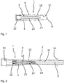
- Fig. 1 shows an electrical component 1 for ignition systems, namely a spark plug connector insert in a longitudinal section.
- the spark plug connector insert 1 is inserted into an outer shell of plastic, such as PTFE, and forms together with this shell the spark plug.
- the Spark plug connector insert 1 is around the in Fig. 1 Dashed longitudinal axis X constructed rotationally symmetrical.
- an electrical functional part 2 is arranged inside the spark plug connector insert 1.
- the electrical functional part 2 consists of a plug-shaped contacting element 21 at one end and a sleeve-like contacting element 22 at the other end and a resistor 23 arranged between the two contacting elements 21, 22.
- the spark plug connector insert 1 an insulator 3, which is formed substantially as a cylindrical hollow body.
- the insulator 3 consists of a thermoplastic material, in particular polyphenylene sulfide with glass fiber content, which has been produced by injection molding.
- the electrical functional part 2 of the in Fig. 1 left side inserted.
- the electrical functional part 2 is inserted with its plug-like contacting element 21 defined on an inner, flange-like projection 32 of the insulator 3.
- a gap which is potted with a potting compound 4 bubbles and crack-free.
- the potting compound 4 is a high-voltage resistant epoxy resin, which is preferably poured under vacuum of 30 - 10 mbar in the gap.
- a spark plug 1 ' is shown, which is an elongated injection molded
- Insulator 3 ' which already reflects the complete outer shape of the spark plug 1'.
- Functionally identical components for in Fig. 1 described embodiment of a spark plug connector insert 1 are here in Fig. 2 in the spark plug 1 'with the same reference numerals.
- the elongated insulator 3 ' is also provided as a hollow body with a continuous cavity 31. Narrowing in the continuous cavity 31, a flange-like projection 32 is formed, which is the electrical Function part 2 as for Fig. 1 described, receives and fixes.
- the electrical functional part 2 consisting of steckermém contacting element 21, muff-like contacting element 22 and the two contacting elements 21 and 22 connecting resistor 23 of the plane in Fig. 2 Inserted to the left in the elongated insulator 3 'in its continuous cavity 31 to the flange-like projection 32, on which the plug-type contacting element 21 is held.
- the intermediate space formed between the electrical functional part 2 and the insulator 3 ' is then potted with the potting compound 4, for example an epoxy resin, preferably under vacuum.
- the advantage in the embodiment according to Fig. 2 lies in the fact that the entire spark plug in its outer boundary of an elongated insulator 3 'is formed, which simultaneously accommodates the inside and the electrical functional part 2, while providing the required electrical insulation. Furthermore, the plastic used for the insulator 3 ', namely preferably polyphenylene sulfide with glass fiber content, in addition to the high dielectric strength of in particular 25 kV / mm also has a high mechanical strength and temperature resistance.
- the spark plug is particularly suitable for
- the elongated insulator 3 'designed as a spark plug connector shell can be inexpensively manufactured by injection molding from the glass-fiber-reinforced polyphenylene sulfide, subsequently fitted with the electrical functional part 2 and then cast with the potting compound, whereby only a three-step process for the Manufacture of the spark plug connector is required.
Landscapes
- Engineering & Computer Science (AREA)
- Manufacturing & Machinery (AREA)
- Mechanical Engineering (AREA)
- Spark Plugs (AREA)
- Injection Moulding Of Plastics Or The Like (AREA)
- Compositions Of Macromolecular Compounds (AREA)
- Casting Or Compression Moulding Of Plastics Or The Like (AREA)
Priority Applications (1)
| Application Number | Priority Date | Filing Date | Title |
|---|---|---|---|
| PL11782371T PL2569833T3 (pl) | 2010-05-11 | 2011-05-06 | Sposób wytwarzania komponentu elektrycznego i komponent elektryczny |
Applications Claiming Priority (2)
| Application Number | Priority Date | Filing Date | Title |
|---|---|---|---|
| DE102010016881A DE102010016881A1 (de) | 2010-05-11 | 2010-05-11 | Herstellungsverfahren für elektrisches Bauteil sowie elektrisches Bauteil |
| PCT/DE2011/075101 WO2012022307A1 (de) | 2010-05-11 | 2011-05-06 | Herstellungsverfahren für elektrisches bauteil sowie elektrisches bauteil |
Publications (2)
| Publication Number | Publication Date |
|---|---|
| EP2569833A1 EP2569833A1 (de) | 2013-03-20 |
| EP2569833B1 true EP2569833B1 (de) | 2018-06-27 |
Family
ID=44859495
Family Applications (1)
| Application Number | Title | Priority Date | Filing Date |
|---|---|---|---|
| EP11782371.6A Active EP2569833B1 (de) | 2010-05-11 | 2011-05-06 | Herstellungsverfahren für elektrisches bauteil sowie elektrisches bauteil |
Country Status (6)
| Country | Link |
|---|---|
| US (1) | US9004929B2 (pl) |
| EP (1) | EP2569833B1 (pl) |
| DE (1) | DE102010016881A1 (pl) |
| ES (1) | ES2688799T3 (pl) |
| PL (1) | PL2569833T3 (pl) |
| WO (1) | WO2012022307A1 (pl) |
Families Citing this family (3)
| Publication number | Priority date | Publication date | Assignee | Title |
|---|---|---|---|---|
| DE202011050966U1 (de) | 2011-08-11 | 2011-10-13 | Motortech Gmbh | Zündkerzenstecker |
| DE102013106218A1 (de) * | 2013-06-14 | 2014-04-24 | Federal-Mogul Ignition Gmbh | Zündkerze |
| US10511152B2 (en) * | 2017-04-26 | 2019-12-17 | Woodward, Inc. | Method and system for a unique material and geometry in a high temperature spark plug extender |
Citations (1)
| Publication number | Priority date | Publication date | Assignee | Title |
|---|---|---|---|---|
| GB2200258A (en) * | 1987-01-20 | 1988-07-27 | Bremicker Auto Elektrik | Spark plug interference suppressor |
Family Cites Families (9)
| Publication number | Priority date | Publication date | Assignee | Title |
|---|---|---|---|---|
| US2399402A (en) * | 1941-04-08 | 1946-04-30 | Bendix Aviat Corp | Electrical connecting and radioshielding means |
| DE2261103A1 (de) | 1972-12-14 | 1974-06-20 | Kabel Metallwerke Ghh | Zuendkerzenstecker fuer verbrennungsmotoren |
| DE3843943A1 (de) * | 1988-12-24 | 1990-06-28 | Asea Brown Boveri | Stromrichtergehaeuse und verfahren zur herstellung von durchfuehrungsanordnungen an diesem gehaeuse |
| JPH0346782A (ja) | 1989-07-14 | 1991-02-28 | Yazaki Corp | 高圧ケーブル装置の製造法 |
| JPH0785908A (ja) | 1993-09-20 | 1995-03-31 | Sumitomo Wiring Syst Ltd | 点火プラグキャップ |
| JP2004200656A (ja) | 2002-12-05 | 2004-07-15 | Denso Corp | 点火コイル |
| JP2010517834A (ja) * | 2007-02-15 | 2010-05-27 | ビーエーエスエフ ソシエタス・ヨーロピア | コンポーネントの製造法ならびにコンポーネント |
| WO2009103713A1 (de) * | 2008-02-18 | 2009-08-27 | Basf Se | Isolator zur elektrischen isolierung sowie verfahren zu seiner herstellung und verwendung |
| DE202009005377U1 (de) * | 2008-04-14 | 2009-07-30 | Kuvag Gmbh & Co Kg | Eingießteil und Bauteil mit derartigem Eingießteil |
-
2010
- 2010-05-11 DE DE102010016881A patent/DE102010016881A1/de not_active Ceased
-
2011
- 2011-05-06 US US13/695,657 patent/US9004929B2/en active Active
- 2011-05-06 WO PCT/DE2011/075101 patent/WO2012022307A1/de not_active Ceased
- 2011-05-06 PL PL11782371T patent/PL2569833T3/pl unknown
- 2011-05-06 EP EP11782371.6A patent/EP2569833B1/de active Active
- 2011-05-06 ES ES11782371.6T patent/ES2688799T3/es active Active
Patent Citations (1)
| Publication number | Priority date | Publication date | Assignee | Title |
|---|---|---|---|---|
| GB2200258A (en) * | 1987-01-20 | 1988-07-27 | Bremicker Auto Elektrik | Spark plug interference suppressor |
Also Published As
| Publication number | Publication date |
|---|---|
| WO2012022307A1 (de) | 2012-02-23 |
| DE102010016881A1 (de) | 2011-11-17 |
| US9004929B2 (en) | 2015-04-14 |
| EP2569833A1 (de) | 2013-03-20 |
| ES2688799T3 (es) | 2018-11-07 |
| US20130052844A1 (en) | 2013-02-28 |
| PL2569833T3 (pl) | 2019-05-31 |
Similar Documents
| Publication | Publication Date | Title |
|---|---|---|
| EP1920451B1 (de) | Verfahren zur herstellung von schalterpolteilen für nieder-, mittel- und hochspannungsschaltanlagen, sowie schalterpolteil selbst | |
| DE3034579A1 (de) | Hochspannungs-freiluft-kunststoffisolator und verfahren zu seiner herstellung | |
| DE3507509A1 (de) | Hochspannungsfestes bauteil und verfahren zu seiner herstellung | |
| EP1554742B1 (de) | Herstellung eines feststoffisolierten schalterpols | |
| US4500745A (en) | Hybrid electrical insulator bushing | |
| DE202010014320U1 (de) | Vorrichtung zur Herstellung eines Leistungsschalter-Polteils | |
| EP2569833B1 (de) | Herstellungsverfahren für elektrisches bauteil sowie elektrisches bauteil | |
| EP3821260B1 (de) | Spannungsteilungsvorrichtung mit stäbchenstruktur | |
| DE69619612T2 (de) | Verfahren zur Herstellung eines Isolators und mit diesem Verfahren hergestellter Isolator | |
| DE3048803A1 (de) | "hochspannungs-spulenanordnung" | |
| WO2012163561A1 (de) | Elektrische komponente für eine hochspannungsanlage | |
| DE19650579A1 (de) | Überspannungsableiter | |
| EP3142206B1 (de) | Gleichspannungs-hochspannungsisolator zur isolierung eines mit gleichspannung beaufschlagten leiters und zugehöriges herstellungsverfahren | |
| EP3093938B1 (de) | Hochspannungs-durchführungssystem | |
| DE10356745B4 (de) | Zündspulenvorrichtung und Herstellungsverfahren dafür | |
| EP3821259B1 (de) | Spannungsteilungsvorrichtung mit siloxan-dielektrikum | |
| DE10356742A1 (de) | Zündspulenvorrichtung | |
| DE10231510B3 (de) | Abdichtung einer Zündspule | |
| DE102015009045A1 (de) | Über Verfahren zur Herstellung eines Überspannungsableiters, Vorrichtung zur Durchführung des Verfahrens und Überspannungsableiter hergestellt gemäß dem Verfahren. | |
| DE602006000042T2 (de) | Radiofrequenzplasmazündkerze für gesteuerte Zündung von Verbrennungsmotoren | |
| DE102019212461B4 (de) | Verfahren zum Verbinden und Abdichten von elektrischen Komponenten | |
| DE102018206148A1 (de) | Steuerelektrode und Durchführung für Mittelspannungsanlagen und Hochspannungsanlagen | |
| DE19804159A1 (de) | Verbindungsmuffe und Verfahren zu ihrer Herstellung | |
| DE10257101B3 (de) | Stabzündspule | |
| DE102005036445A1 (de) | Zündspule für eine Brennkraftmaschine |
Legal Events
| Date | Code | Title | Description |
|---|---|---|---|
| PUAI | Public reference made under article 153(3) epc to a published international application that has entered the european phase |
Free format text: ORIGINAL CODE: 0009012 |
|
| 17P | Request for examination filed |
Effective date: 20121011 |
|
| AK | Designated contracting states |
Kind code of ref document: A1 Designated state(s): AL AT BE BG CH CY CZ DE DK EE ES FI FR GB GR HR HU IE IS IT LI LT LU LV MC MK MT NL NO PL PT RO RS SE SI SK SM TR |
|
| DAX | Request for extension of the european patent (deleted) | ||
| 17Q | First examination report despatched |
Effective date: 20161010 |
|
| STAA | Information on the status of an ep patent application or granted ep patent |
Free format text: STATUS: EXAMINATION IS IN PROGRESS |
|
| GRAP | Despatch of communication of intention to grant a patent |
Free format text: ORIGINAL CODE: EPIDOSNIGR1 |
|
| STAA | Information on the status of an ep patent application or granted ep patent |
Free format text: STATUS: GRANT OF PATENT IS INTENDED |
|
| INTG | Intention to grant announced |
Effective date: 20180216 |
|
| GRAS | Grant fee paid |
Free format text: ORIGINAL CODE: EPIDOSNIGR3 |
|
| GRAA | (expected) grant |
Free format text: ORIGINAL CODE: 0009210 |
|
| STAA | Information on the status of an ep patent application or granted ep patent |
Free format text: STATUS: THE PATENT HAS BEEN GRANTED |
|
| AK | Designated contracting states |
Kind code of ref document: B1 Designated state(s): AL AT BE BG CH CY CZ DE DK EE ES FI FR GB GR HR HU IE IS IT LI LT LU LV MC MK MT NL NO PL PT RO RS SE SI SK SM TR |
|
| REG | Reference to a national code |
Ref country code: GB Ref legal event code: FG4D Free format text: NOT ENGLISH |
|
| REG | Reference to a national code |
Ref country code: AT Ref legal event code: REF Ref document number: 1013134 Country of ref document: AT Kind code of ref document: T Effective date: 20180715 |
|
| REG | Reference to a national code |
Ref country code: DE Ref legal event code: R096 Ref document number: 502011014385 Country of ref document: DE |
|
| REG | Reference to a national code |
Ref country code: IE Ref legal event code: FG4D Free format text: LANGUAGE OF EP DOCUMENT: GERMAN |
|
| PG25 | Lapsed in a contracting state [announced via postgrant information from national office to epo] |
Ref country code: NO Free format text: LAPSE BECAUSE OF FAILURE TO SUBMIT A TRANSLATION OF THE DESCRIPTION OR TO PAY THE FEE WITHIN THE PRESCRIBED TIME-LIMIT Effective date: 20180927 Ref country code: BG Free format text: LAPSE BECAUSE OF FAILURE TO SUBMIT A TRANSLATION OF THE DESCRIPTION OR TO PAY THE FEE WITHIN THE PRESCRIBED TIME-LIMIT Effective date: 20180927 Ref country code: FI Free format text: LAPSE BECAUSE OF FAILURE TO SUBMIT A TRANSLATION OF THE DESCRIPTION OR TO PAY THE FEE WITHIN THE PRESCRIBED TIME-LIMIT Effective date: 20180627 Ref country code: SE Free format text: LAPSE BECAUSE OF FAILURE TO SUBMIT A TRANSLATION OF THE DESCRIPTION OR TO PAY THE FEE WITHIN THE PRESCRIBED TIME-LIMIT Effective date: 20180627 Ref country code: LT Free format text: LAPSE BECAUSE OF FAILURE TO SUBMIT A TRANSLATION OF THE DESCRIPTION OR TO PAY THE FEE WITHIN THE PRESCRIBED TIME-LIMIT Effective date: 20180627 |
|
| REG | Reference to a national code |
Ref country code: NL Ref legal event code: MP Effective date: 20180627 |
|
| REG | Reference to a national code |
Ref country code: ES Ref legal event code: FG2A Ref document number: 2688799 Country of ref document: ES Kind code of ref document: T3 Effective date: 20181107 |
|
| REG | Reference to a national code |
Ref country code: LT Ref legal event code: MG4D |
|
| PG25 | Lapsed in a contracting state [announced via postgrant information from national office to epo] |
Ref country code: RS Free format text: LAPSE BECAUSE OF FAILURE TO SUBMIT A TRANSLATION OF THE DESCRIPTION OR TO PAY THE FEE WITHIN THE PRESCRIBED TIME-LIMIT Effective date: 20180627 Ref country code: HR Free format text: LAPSE BECAUSE OF FAILURE TO SUBMIT A TRANSLATION OF THE DESCRIPTION OR TO PAY THE FEE WITHIN THE PRESCRIBED TIME-LIMIT Effective date: 20180627 Ref country code: LV Free format text: LAPSE BECAUSE OF FAILURE TO SUBMIT A TRANSLATION OF THE DESCRIPTION OR TO PAY THE FEE WITHIN THE PRESCRIBED TIME-LIMIT Effective date: 20180627 Ref country code: GR Free format text: LAPSE BECAUSE OF FAILURE TO SUBMIT A TRANSLATION OF THE DESCRIPTION OR TO PAY THE FEE WITHIN THE PRESCRIBED TIME-LIMIT Effective date: 20180928 |
|
| REG | Reference to a national code |
Ref country code: CH Ref legal event code: NV Representative=s name: E. BLUM AND CO. AG PATENT- UND MARKENANWAELTE , CH |
|
| PG25 | Lapsed in a contracting state [announced via postgrant information from national office to epo] |
Ref country code: NL Free format text: LAPSE BECAUSE OF FAILURE TO SUBMIT A TRANSLATION OF THE DESCRIPTION OR TO PAY THE FEE WITHIN THE PRESCRIBED TIME-LIMIT Effective date: 20180627 |
|
| PG25 | Lapsed in a contracting state [announced via postgrant information from national office to epo] |
Ref country code: EE Free format text: LAPSE BECAUSE OF FAILURE TO SUBMIT A TRANSLATION OF THE DESCRIPTION OR TO PAY THE FEE WITHIN THE PRESCRIBED TIME-LIMIT Effective date: 20180627 Ref country code: IS Free format text: LAPSE BECAUSE OF FAILURE TO SUBMIT A TRANSLATION OF THE DESCRIPTION OR TO PAY THE FEE WITHIN THE PRESCRIBED TIME-LIMIT Effective date: 20181027 Ref country code: RO Free format text: LAPSE BECAUSE OF FAILURE TO SUBMIT A TRANSLATION OF THE DESCRIPTION OR TO PAY THE FEE WITHIN THE PRESCRIBED TIME-LIMIT Effective date: 20180627 Ref country code: SK Free format text: LAPSE BECAUSE OF FAILURE TO SUBMIT A TRANSLATION OF THE DESCRIPTION OR TO PAY THE FEE WITHIN THE PRESCRIBED TIME-LIMIT Effective date: 20180627 |
|
| PG25 | Lapsed in a contracting state [announced via postgrant information from national office to epo] |
Ref country code: IT Free format text: LAPSE BECAUSE OF FAILURE TO SUBMIT A TRANSLATION OF THE DESCRIPTION OR TO PAY THE FEE WITHIN THE PRESCRIBED TIME-LIMIT Effective date: 20180627 Ref country code: SM Free format text: LAPSE BECAUSE OF FAILURE TO SUBMIT A TRANSLATION OF THE DESCRIPTION OR TO PAY THE FEE WITHIN THE PRESCRIBED TIME-LIMIT Effective date: 20180627 |
|
| REG | Reference to a national code |
Ref country code: DE Ref legal event code: R097 Ref document number: 502011014385 Country of ref document: DE |
|
| PLBE | No opposition filed within time limit |
Free format text: ORIGINAL CODE: 0009261 |
|
| STAA | Information on the status of an ep patent application or granted ep patent |
Free format text: STATUS: NO OPPOSITION FILED WITHIN TIME LIMIT |
|
| PG25 | Lapsed in a contracting state [announced via postgrant information from national office to epo] |
Ref country code: DK Free format text: LAPSE BECAUSE OF FAILURE TO SUBMIT A TRANSLATION OF THE DESCRIPTION OR TO PAY THE FEE WITHIN THE PRESCRIBED TIME-LIMIT Effective date: 20180627 |
|
| 26N | No opposition filed |
Effective date: 20190328 |
|
| PG25 | Lapsed in a contracting state [announced via postgrant information from national office to epo] |
Ref country code: SI Free format text: LAPSE BECAUSE OF FAILURE TO SUBMIT A TRANSLATION OF THE DESCRIPTION OR TO PAY THE FEE WITHIN THE PRESCRIBED TIME-LIMIT Effective date: 20180627 |
|
| PG25 | Lapsed in a contracting state [announced via postgrant information from national office to epo] |
Ref country code: AL Free format text: LAPSE BECAUSE OF FAILURE TO SUBMIT A TRANSLATION OF THE DESCRIPTION OR TO PAY THE FEE WITHIN THE PRESCRIBED TIME-LIMIT Effective date: 20180627 |
|
| PG25 | Lapsed in a contracting state [announced via postgrant information from national office to epo] |
Ref country code: MC Free format text: LAPSE BECAUSE OF FAILURE TO SUBMIT A TRANSLATION OF THE DESCRIPTION OR TO PAY THE FEE WITHIN THE PRESCRIBED TIME-LIMIT Effective date: 20180627 |
|
| REG | Reference to a national code |
Ref country code: BE Ref legal event code: MM Effective date: 20190531 |
|
| PG25 | Lapsed in a contracting state [announced via postgrant information from national office to epo] |
Ref country code: LU Free format text: LAPSE BECAUSE OF NON-PAYMENT OF DUE FEES Effective date: 20190506 |
|
| PG25 | Lapsed in a contracting state [announced via postgrant information from national office to epo] |
Ref country code: TR Free format text: LAPSE BECAUSE OF FAILURE TO SUBMIT A TRANSLATION OF THE DESCRIPTION OR TO PAY THE FEE WITHIN THE PRESCRIBED TIME-LIMIT Effective date: 20180627 |
|
| PG25 | Lapsed in a contracting state [announced via postgrant information from national office to epo] |
Ref country code: IE Free format text: LAPSE BECAUSE OF NON-PAYMENT OF DUE FEES Effective date: 20190506 |
|
| PG25 | Lapsed in a contracting state [announced via postgrant information from national office to epo] |
Ref country code: BE Free format text: LAPSE BECAUSE OF NON-PAYMENT OF DUE FEES Effective date: 20190531 |
|
| PG25 | Lapsed in a contracting state [announced via postgrant information from national office to epo] |
Ref country code: PT Free format text: LAPSE BECAUSE OF FAILURE TO SUBMIT A TRANSLATION OF THE DESCRIPTION OR TO PAY THE FEE WITHIN THE PRESCRIBED TIME-LIMIT Effective date: 20181029 |
|
| PG25 | Lapsed in a contracting state [announced via postgrant information from national office to epo] |
Ref country code: CY Free format text: LAPSE BECAUSE OF FAILURE TO SUBMIT A TRANSLATION OF THE DESCRIPTION OR TO PAY THE FEE WITHIN THE PRESCRIBED TIME-LIMIT Effective date: 20180627 |
|
| PG25 | Lapsed in a contracting state [announced via postgrant information from national office to epo] |
Ref country code: MT Free format text: LAPSE BECAUSE OF FAILURE TO SUBMIT A TRANSLATION OF THE DESCRIPTION OR TO PAY THE FEE WITHIN THE PRESCRIBED TIME-LIMIT Effective date: 20180627 Ref country code: HU Free format text: LAPSE BECAUSE OF FAILURE TO SUBMIT A TRANSLATION OF THE DESCRIPTION OR TO PAY THE FEE WITHIN THE PRESCRIBED TIME-LIMIT; INVALID AB INITIO Effective date: 20110506 |
|
| PG25 | Lapsed in a contracting state [announced via postgrant information from national office to epo] |
Ref country code: MK Free format text: LAPSE BECAUSE OF FAILURE TO SUBMIT A TRANSLATION OF THE DESCRIPTION OR TO PAY THE FEE WITHIN THE PRESCRIBED TIME-LIMIT Effective date: 20180627 |
|
| REG | Reference to a national code |
Ref country code: FR Ref legal event code: PLFP Year of fee payment: 13 |
|
| PGFP | Annual fee paid to national office [announced via postgrant information from national office to epo] |
Ref country code: DE Payment date: 20250409 Year of fee payment: 15 |
|
| PGFP | Annual fee paid to national office [announced via postgrant information from national office to epo] |
Ref country code: ES Payment date: 20250609 Year of fee payment: 15 |
|
| PGFP | Annual fee paid to national office [announced via postgrant information from national office to epo] |
Ref country code: FR Payment date: 20250409 Year of fee payment: 15 |
|
| PGFP | Annual fee paid to national office [announced via postgrant information from national office to epo] |
Ref country code: CH Payment date: 20250601 Year of fee payment: 15 |
|
| PGFP | Annual fee paid to national office [announced via postgrant information from national office to epo] |
Ref country code: AT Payment date: 20250425 Year of fee payment: 15 |
|
| PGFP | Annual fee paid to national office [announced via postgrant information from national office to epo] |
Ref country code: CZ Payment date: 20250414 Year of fee payment: 15 |
|
| PGFP | Annual fee paid to national office [announced via postgrant information from national office to epo] |
Ref country code: GB Payment date: 20260320 Year of fee payment: 16 |
|
| PGFP | Annual fee paid to national office [announced via postgrant information from national office to epo] |
Ref country code: PL Payment date: 20260327 Year of fee payment: 16 |