EP2569642B1 - Pipettiereinrichtung und verfahren zur steuerung einer pipettiereinrichtung oder erzeugen von flüssigkeits-aliquoten - Google Patents
Pipettiereinrichtung und verfahren zur steuerung einer pipettiereinrichtung oder erzeugen von flüssigkeits-aliquoten Download PDFInfo
- Publication number
- EP2569642B1 EP2569642B1 EP10720750.8A EP10720750A EP2569642B1 EP 2569642 B1 EP2569642 B1 EP 2569642B1 EP 10720750 A EP10720750 A EP 10720750A EP 2569642 B1 EP2569642 B1 EP 2569642B1
- Authority
- EP
- European Patent Office
- Prior art keywords
- pipettes
- sets
- arrangement
- aspiration port
- pipetting
- Prior art date
- Legal status (The legal status is an assumption and is not a legal conclusion. Google has not performed a legal analysis and makes no representation as to the accuracy of the status listed.)
- Active
Links
Images


Classifications
-
- G—PHYSICS
- G01—MEASURING; TESTING
- G01N—INVESTIGATING OR ANALYSING MATERIALS BY DETERMINING THEIR CHEMICAL OR PHYSICAL PROPERTIES
- G01N35/00—Automatic analysis not limited to methods or materials provided for in any single one of groups G01N1/00 - G01N33/00; Handling materials therefor
- G01N35/10—Devices for transferring samples or any liquids to, in, or from, the analysis apparatus, e.g. suction devices, injection devices
- G01N35/1009—Characterised by arrangements for controlling the aspiration or dispense of liquids
-
- B—PERFORMING OPERATIONS; TRANSPORTING
- B01—PHYSICAL OR CHEMICAL PROCESSES OR APPARATUS IN GENERAL
- B01L—CHEMICAL OR PHYSICAL LABORATORY APPARATUS FOR GENERAL USE
- B01L3/00—Containers or dishes for laboratory use, e.g. laboratory glassware; Droppers
- B01L3/02—Burettes; Pipettes
- B01L3/021—Pipettes, i.e. with only one conduit for withdrawing and redistributing liquids
-
- G—PHYSICS
- G01—MEASURING; TESTING
- G01N—INVESTIGATING OR ANALYSING MATERIALS BY DETERMINING THEIR CHEMICAL OR PHYSICAL PROPERTIES
- G01N35/00—Automatic analysis not limited to methods or materials provided for in any single one of groups G01N1/00 - G01N33/00; Handling materials therefor
- G01N35/10—Devices for transferring samples or any liquids to, in, or from, the analysis apparatus, e.g. suction devices, injection devices
- G01N35/1009—Characterised by arrangements for controlling the aspiration or dispense of liquids
- G01N35/1011—Control of the position or alignment of the transfer device
-
- G—PHYSICS
- G01—MEASURING; TESTING
- G01N—INVESTIGATING OR ANALYSING MATERIALS BY DETERMINING THEIR CHEMICAL OR PHYSICAL PROPERTIES
- G01N35/00—Automatic analysis not limited to methods or materials provided for in any single one of groups G01N1/00 - G01N33/00; Handling materials therefor
- G01N35/10—Devices for transferring samples or any liquids to, in, or from, the analysis apparatus, e.g. suction devices, injection devices
- G01N35/1065—Multiple transfer devices
- G01N35/1072—Multiple transfer devices with provision for selective pipetting of individual channels
-
- B—PERFORMING OPERATIONS; TRANSPORTING
- B01—PHYSICAL OR CHEMICAL PROCESSES OR APPARATUS IN GENERAL
- B01L—CHEMICAL OR PHYSICAL LABORATORY APPARATUS FOR GENERAL USE
- B01L2300/00—Additional constructional details
- B01L2300/08—Geometry, shape and general structure
- B01L2300/0861—Configuration of multiple channels and/or chambers in a single devices
-
- B—PERFORMING OPERATIONS; TRANSPORTING
- B01—PHYSICAL OR CHEMICAL PROCESSES OR APPARATUS IN GENERAL
- B01L—CHEMICAL OR PHYSICAL LABORATORY APPARATUS FOR GENERAL USE
- B01L2400/00—Moving or stopping fluids
- B01L2400/04—Moving fluids with specific forces or mechanical means
- B01L2400/0475—Moving fluids with specific forces or mechanical means specific mechanical means and fluid pressure
- B01L2400/0487—Moving fluids with specific forces or mechanical means specific mechanical means and fluid pressure fluid pressure, pneumatics
-
- B—PERFORMING OPERATIONS; TRANSPORTING
- B01—PHYSICAL OR CHEMICAL PROCESSES OR APPARATUS IN GENERAL
- B01L—CHEMICAL OR PHYSICAL LABORATORY APPARATUS FOR GENERAL USE
- B01L2400/00—Moving or stopping fluids
- B01L2400/06—Valves, specific forms thereof
- B01L2400/0694—Valves, specific forms thereof vents used to stop and induce flow, backpressure valves
-
- B—PERFORMING OPERATIONS; TRANSPORTING
- B01—PHYSICAL OR CHEMICAL PROCESSES OR APPARATUS IN GENERAL
- B01L—CHEMICAL OR PHYSICAL LABORATORY APPARATUS FOR GENERAL USE
- B01L2400/00—Moving or stopping fluids
- B01L2400/08—Regulating or influencing the flow resistance
- B01L2400/082—Active control of flow resistance, e.g. flow controllers
-
- Y—GENERAL TAGGING OF NEW TECHNOLOGICAL DEVELOPMENTS; GENERAL TAGGING OF CROSS-SECTIONAL TECHNOLOGIES SPANNING OVER SEVERAL SECTIONS OF THE IPC; TECHNICAL SUBJECTS COVERED BY FORMER USPC CROSS-REFERENCE ART COLLECTIONS [XRACs] AND DIGESTS
- Y10—TECHNICAL SUBJECTS COVERED BY FORMER USPC
- Y10T—TECHNICAL SUBJECTS COVERED BY FORMER US CLASSIFICATION
- Y10T137/00—Fluid handling
- Y10T137/0318—Processes
Definitions
- the present invention relates to the field of preparing and handling doses of liquids, thereby of very small doses down to e.g. some hundreds nano-liters with accurately predetermined volumes.
- Such liquid handling techniques are especially used in context with medical, chemical or biochemical analyses, e.g. in pharmaceutical, medical or food industry laboratories.
- rated volume of a dose the volume of a dose which is desired.
- a dose as produced should, ideally, have a volume equal to the rated volume.
- the doses of liquids once aspirated into the pipettes are customarily conveyed within the pipettes to a destination location where they are released from the pipettes by respective controls of the valves and pumping arrangements. Subsequently the pipettes can be rinsed with a rinsing solution, if necessary.
- the aspiration steps are performed in that all valves and pumping arrangements, each associated to one pipette, are operated simultaneously or staggered in time.
- Patent application US 2003/215957 discloses a pipetting arrangement comprising at least two sets of pipettes each of said sets of pipettes being operationally connected, via a controllable ON/OFF valve each, to a common aspiration port operationally connected to a pumping arrangement generating an aspiration effect to said aspiration port, said valves being controlled by a timing-control unit conceived to establish, by control of said valves, said operational connections of said at least two sets of pipettes to said aspiration port in a time-multiplexed manner.
- a pipetting arrangement which comprises at least two sets of pipettes.
- Each set of pipettes is operationally connected via a controllable ON/OFF-(open/closed) valve to a common aspiration port.
- the aspiration port is connectable to a pumping arrangement.
- the valves are controlled by a timing-control unit.
- the timing-control unit is conceived to establish, by the control of the valves, the respective operational connections of the at least two sets of pipettes to the aspiration port in a time-multiplexed manner.
- Such pumping arrangement is part of the pipetting arrangement according to the invention; such pumping arrangement may be a remote pumping- or evacuation-station which feeds a line-network in a building installation, may be a pump arrangement centralized for a number of different equipments, or a distinct pump arrangement for the pipetting arrangement, integrated to or remote from a liquid handling device which comprises the addressed pipetting arrangement.
- a pipette a tubular member with one opening for aspiration and release of a liquid product dose and with a second opening whereat aspirating vacuum is controllably applied.
- one set of pipettes after the other is operationally connected to the common aspiration port which is operatively connected to a common pumping arrangement.
- the number of highly sophisticated precision pumps as customarily assigned to each set of pipettes is drastically reduced. If e.g. a customary pipetting arrangement with ten sets of pipettes necessitates ten pumping arrangements, a pipetting arrangement according to the present invention necessitates just one pumping arrangement.
- the multiplexing technique according to the present invention has significant advantages over parallel aspiration techniques, e.g. with respect to constructional efforts, price, constructional volume and weight. Latter is especially important if one keeps in mind, that the overall pipetting arrangement is often moved at high accelerations from a seizing location to a destination location and back. By the reduction of weight of the pipetting arrangement with integrated single pumping arrangement it becomes possible to apply higher conveyance accelerations and /or to reduce driving forces the conveyor system has to stand and thus to optimize subsequent processing steps of liquid dose handling.
- Time-multiplexing under its most generic aspect, associates to each set of pipettes a well defined time slot, during which such set is operationally connected to the aspiration port of or to a common pumping arrangement.
- the extent of these time slots is most accurately controllable and most accurately variable.
- the time-multiplexing technique according to the present invention which exploits a single pumping arrangement for serving the at least two or more sets of pipettes, allows utmost flexibility to serve all sets in multiplexing mode, to serve two or more sets simultaneously and thus in parallel, to group the sets in groups of sets which are served in parallel and time multiplexed with other groups etc.
- At least one of the at least two sets of pipettes comprises one single pipette.
- the pipette arrangement comprises the common pumping arrangement operationally connected to the aspiration port.
- the pumping arrangement is part of the pipetting arrangement according to the invention.
- such pumping arrangement comprises a gear pump, preferably an annular gear pump, as described e.g. in the EP 0 852 674 B1 .
- a gear pump preferably an annular gear pump, as described e.g. in the EP 0 852 674 B1 .
- the timing-control unit which in fact establishes for time-multiplexing, is controllable to alternatively and selectably establish the operational connections of the at least two set of pipettes to the aspiration port simultaneously.
- the timing-control unit which in fact establishes for time-multiplexing, is controllable to alternatively and selectably establish the operational connections of the at least two set of pipettes to the aspiration port simultaneously.
- the pumping arrangement is controlled to be ongoingly operative during establishing, by control of the valves, the operational connections of the at least two sets to the aspiration port in a time-multiplexed manner. This avoids switching the pumping arrangement on and off. In this way the volumes of the aspirated doses is merely defined by the controlled operation of the valves, i.e. the time spans during which the respective valves are open.
- the pumping arrangement is controlled to be intermittently operated in an ON and in an OFF mode, synchronized with establishing, by control of the valves, the operational connections of the at least two sets of pipettes to the aspiration port in a time-multiplexed manner.
- the volumes of the doses as aspired are merely defined by the power of the pumping arrangement and the respective time spans the pumping arrangement is operating.
- valves are tailored to eject or to aspirate a volume which is neglectable when controlled from OFF to ON state or inversely. Thereby accuracy of the aspirated volumes becomes influenced by operation of the valves only to a neglectable amount.
- a flow sensor is provided in a common line from the pumping arrangement to the sets of pipettes. Thereby it becomes possible to monitor with a single flow sensor the flow towards the pumping arrangement, e.g. indicating that one of the pipettes or is blocked.
- a liquid handling device which comprises a pipetting arrangement according to the invention in one or more than one of its specific embodiments, is highly cost effective, exhibits a small volumed and small weighted pipetting arrangement and is most flexibly controllable.
- One embodiment of the liquid handling device according to the invention which may be combined with any other embodiment of such device unless in contradiction, comprises a controlled positioning drive controlling position of the pipetting arrangement along at least two spatial coordinate axes. Thereby the pipetting arrangement is drivingly positioned in respective positions e.g. as defined in an x/y coordinate system.
- the controlled positioning drive controls position of the pipetting arrangement and/or of the two sets in a mutually independent manner, along a third spatial coordinate axis.
- the pipetting arrangement becomes drivingly positionable e.g. with respect to a z coordinate and/or the sets of pipettes become individually and independently positionable with respect to the addressed third spatial coordinate.
- a further object of the present invention is to improve control of a pipetting arrangement or to improve production of liquid doses of predetermined volumes. This is achieved by a method of controlling a pipetting arrangement or of producing at least two liquid doses of predetermined volumes, according to claim 8.
- At least one of the at least two sets of pipettes is selected to comprise one single pipette.
- the aspirating effect is kept ongoing during multiplexing.
- the aspirating effect at said aspiration port is intermittently established, synchronised with the multiplexing.
- an additional, selectable mode of operation wherein the operational connections of the first and second sets of pipettes to the aspiration port are simultaneously established.
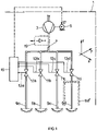
- Fig. 1 schematically shows an embodiment of a pipetting arrangement 1 according to the present invention.
- a pumping arrangement exemplified in the figure by a pump 3 with a drive motor 5 is operationally connected to an aspiration port 7.
- the pumping arrangement may be remote from aspiration port 7 and may be realised e.g. by a central pumping station of a laboratory building feeding a vacuum line network throughout such building.
- the pumping arrangement is integral with the pipetting arrangement and comprises a pump 3.
- the aspiration port 7 is operationally connected to at least two, as exemplified to four sets of pipettes 9a, 9b, 9c and 9d via respective ON/OFF valves 11a, 11b, 11c, 11d, each being ON/OFF controlled by ON/OFF control signals applied to control inputs 13a, 13b, 13c, 13d.
- the valves may be pneumatically controlled or electrically which latter is the case in today's realized embodiment.
- the sets of pipettes may comprise one single pipette as represented in the figure, all of them or selected sets may nevertheless be realized by more than one pipette operated in parallel, as exemplified at 9d' in dash line.
- the ON/Off control signals for the valves 11a to 11d are generated and timed by a timing-control unit 15.
- ON/OFF operation of pump 3 is controlled by a control signal to the drive motor control input 17.
- the control signal to control input 17 is e.g. generated by the timing-control unit 15 as well.
- a pipette 9 is operationally connected to a pumping arrangement, as to a pump 3a via an ON/OFF valve 11.
- the pump 3a on one hand is permanently filled with a liquid medium which is conveyed forth and back by respective operation of the pump 3a as schematically shown by double arrow m.
- the system of pipette 9 and commonly also of valve 11 is filled with a gaseous or liquid medium M, we call this liquid "transmitter medium".
- valve 11 is OFF, i.e. closed and thereby prevents any escape of liquid transmitter medium M from pipette 9, which customarily is vertically oriented.
- the bottom level of liquid transmitter medium M in the pipette 9 is at a predetermined position at or adjacent to the mouth 10 of the pipette.
- the pump 3a is started and simultaneously valve 11 is controlled into ON state, i.e. open state.
- the aspiration effect at the aspiration port 7a to pump 7 is transmitted by the transmitter medium M, irrespective whether liquid or gaseous, to the mouth 10a of the pipette: Dose liquid 21 is aspired into pipette 9.
- valve 11 As soon as a predetermined volume of dose liquid 21 is in the pipette 9 valve 11 is closed.
- the arrangement customary comprising pipette 9, valve 11 and pump 3a is lifted, so that the mouth 10 of pipette is freed from the remaining dosing liquid 21 in a receptacle 22.
- pump 3a Simultaneously with turning valve 11 in OFF (closed) state or shortly before or afterwards, pump 3a is customarily stopped or, more generically an aspirating effect to the pipette is disabled.
- valve 9 For releasing the dose of dosing liquid from pipette 9 into a destination receptacle (not shown), valve 9 is switched ON (open). E.g. the pump 3a is inversed in operation, and thus actively ejects the dose of liquid 21 into the destination receptacle.
- different techniques are known to accurately control that exactly the same dose volume of liquid 21 is ejected into the destination receptacle as has been seized from the "source" recipient 22.
- one pumping arrangement is dedicated to each pipette or set of pipettes.
- pump 3 is provided to serve more than one, as exemplified, four sets of pipettes 9a to 9d. This is done by time-multiplexing the aspiration effect at the aspiration port 7 from pump 3 consecutively to one set of pipettes after the other. Thereby the order of such sequence may be selected as desired, for clearness sake, multiplexing of the aspiration effect shall be from 9a to 9b to 9c to 9d in fig 1 .
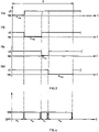
- Fig. 3 qualitatively shows the timing diagram of the multiplexing control of the valves 11a to 11d by the control signals generated by control unit 15 and applied to control inputs 13a to 13d of the respective valves.
- "cl.” addresses “close” ( OFF State) and "op.” addresses "open” (ON state)of the respective valves.
- ⁇ 11a to ⁇ 11d address the respective time slots a respective valve 11a to 11d is open.
- T is the overall cycle time to fill all the four sets of pipettes.
- first valve 11a is opened during time slot ⁇ 11a .
- valve 11a is closed and at least substantially simultaneously, possibly with a small time lag, valve 11b is opened for the time slot ⁇ 11b .
- the sets of pipettes 9c and then 9d are multiplexed to the aspiration effect at port 7 during respective time slots ⁇ 11c , ⁇ 11d .
- the extents and the time sequence of the time slots is freely selectable. Further and if desired it is absolutely possible to flexibly establish two or more of the time slots to occur simultaneously or overlappingly and thereby to operate respectively selected sets- if desired even all sets- simultaneously and thus in parallel. Still further and if desired one set considered may be operated during more than one time slot. This e.g. if a fixed time slot duration for all sets is established, in the sense of a system clock, and doses of different volumes are to be aspirated at different sets of pipettes.
- a gear pump preferably an annular gear pump as described e.g. in the EP 0 852 674 B1 is integrated to the pipetting arrangement thereby forming with the addressed arrangement a commonly moved and positioned unit.
- the extents of the multiplexing time slots ⁇ 11x may be selected to be equal or, as shown, different. Thereby by means of controlling the extents of these time slots ⁇ 11x the volume of each aspirated dose may be separately selected.
- pump 3 operates ongoingly during cycle time T and thereby performing multiplexing the aspiration effect merely by ON/OFF control of the valves 11a to 11d; in an example which is not part of the present invention it is possible to operate the pump 3 intermittently, synchronized with multiplexing.
- Fig. 4 shows, associated with fig.3 , a timing diagram of such intermittent pump operation, which is not part of the present invention.
- the respective ON times ⁇ a to ⁇ d of the pump control the respectively aspirated volumes of the doses, whereas the valves 11a to 11d control time multiplexing and accurate retention of the aspirated dosing liquid within the sets of pipettes.
- valves 11a to 11d should propel a vanishing volume of transmitter medium M (see fig.2 ) in the transients ON to OFF and OFF to ON, so as not to falsify the aspirated volume of the respective doses controlled on one hand by the operation state of the pump and, on the other hand, by the respective time spans ⁇ a to ⁇ d .
- Fig. 5 schematically shows a liquid handling apparatus or device 33 with a pipetting arrangement 1 according to the present invention integrated in a conveyor arm 34.
- the conveyor arm 34 provides for driven movability of the pipettes 9 in x- and z-direction as is schematically shown in fig. 1 with respect to an apparatus frame 35.
- the arm 34 itself is drivingly movable in y-direction with respect to the frame 35.
- the valves 11 as well as pump 3 are integrated in the arrangement 1.
- the sets of pipettes 9 can be dipped by controlled movement in z-direction into sample receptacles 37 with the respective dose liquids.
- the aspirated doses are then conveyed in x and y direction to destination receptacles 39.
- all the sets of pipettes are commonly driven and positioned in z-direction, in an other embodiment (not shown) distinct sets or groups of sets may be driven and positioned in z direction mutually independently.
Landscapes
- Chemical & Material Sciences (AREA)
- Health & Medical Sciences (AREA)
- General Health & Medical Sciences (AREA)
- Life Sciences & Earth Sciences (AREA)
- Analytical Chemistry (AREA)
- Biochemistry (AREA)
- Physics & Mathematics (AREA)
- General Physics & Mathematics (AREA)
- Immunology (AREA)
- Pathology (AREA)
- Clinical Laboratory Science (AREA)
- Chemical Kinetics & Catalysis (AREA)
- Automatic Analysis And Handling Materials Therefor (AREA)
- Sampling And Sample Adjustment (AREA)
Claims (11)
- Pipettieranordnung, umfassend mindestens zwei Pipettensätze (9a bis 9d'), wobei jeder der Pipettensätze jeweils über ein steuerbares EIN/AUS-Ventil (11a bis 11d) mit einer gemeinsamen Ansaugöffnung (7) wirkverbunden ist, die mit einer Pumpanordnung (3, 5) wirkverbunden ist, die eine Ansaugwirkung zu der Ansaugöffnung erzeugt, wobei die Ventile (11a bis 11d) durch eine Zeitsteuereinheit (15) gesteuert werden, die dazu konzipiert ist, durch eine Steuerung der Ventile (11a bis 11d) die Wirkverbindungen der mindestens zwei Pipettensätze (9a bis 9d') mit der Ansaugöffnung auf eine zeitmultiplexierte Weise herzustellen,dadurch gekennzeichnet, dassdie Pumpanordnung (3, 5) derart gesteuert wird, dass sie während des Herstellens der Wirkverbindungen der mindestens zwei Pipettensätze (9a bis 9d') mit der Ansaugöffnung (7) auf die zeitmultiplexierte Weise durch die Steuerung der Ventile (11a bis 11d) durchgehend in Betrieb ist, undwobei die Pipettieranordnung dazu konfiguriert ist, Volumen angesaugter Dosen allein durch den gesteuerten Betrieb der Ventile zu definieren.
- Pipettieranordnung nach Anspruch 1, wobei mindestens einer der Sätze eine einzelne Pipette (9a bis 9c) umfasst.
- Pipettieranordnung nach einem der Ansprüche 1 oder 2, wobei die Steuereinheit steuerbar ist, um wahlweise und selektiv die Wirkverbindungen gleichzeitig herzustellen.
- Pipettieranordnung nach einem der Ansprüche 1 bis 3, umfassend einen Durchflusssensor (19), der zwischen den Pipettensätzen (9a bis 9d) und der Pumpanordnung (3) verbunden ist.
- Flüssigkeitshandhabungsvorrichtung, umfassend eine Pipettieranordnung nach einem der Ansprüche 1 bis 4.
- Flüssigkeitshandhabungsvorrichtung nach Anspruch 5, umfassend einen Antrieb (34) zur gesteuerten Positionierung, der die Position der Pipettieranordnung entlang von mindestens zwei räumlichen Koordinatenachsen steuert.
- Flüssigkeitshandhabungsvorrichtung nach Anspruch 6, wobei der Antrieb (34) zur gesteuerten Positionierung die Position der Pipettieranordnung und/oder der mindestens zwei Sätze auf wechselseitig unabhängige Weise entlang einer dritten räumlichen Koordinatenachse steuert.
- Verfahren zur Steuerung einer Pipettieranordnung oder zur Herstellung von mindestens zwei Flüssigkeitsdosen mit vorbestimmen Volumen, umfassend• Eintauchen eines ersten von mindestens zwei Pipettensätzen (9a bis 9d) in einen ersten Behälter (22), der eine erste Flüssigkeit (21) enthält, Wirkverbinden des ersten Pipettensatzes mit einer Ansaugöffnung (7), die mit einer Pumpanordnung (3, 5) wirkverbunden ist und Herstellen einer Ansaugwirkung an der Ansaugöffnung, wodurch eine erste Flüssigkeit in den ersten Pipettensatz angesaugt wird;• Schließen eines ersten EIN/AUS-Ventils (11), das zwischen dem ersten Pipettensatz und der Ansaugöffnung (7) verbunden ist;• Eintauchen eines zweiten Satzes von den mindestens zwei Pipettensätzen (9a bis 9d') in einen zweiten Behälter (22), der eine zweite Flüssigkeit (21) enthält, Wirkverbinden des zweiten Pipettensatzes mit der Ansaugöffnung (7), die mit der Pumpanordnung (3, 5) wirkverbunden ist und Herstellen einer Ansaugwirkung an der Ansaugöffnung, wodurch die zweite Flüssigkeit in den zweiten Pipettensatz angesaugt wird;• Schließen eines zweiten EIN/AUS-Ventils (11), das zwischen dem zweiten Pipettensatz und der Ansaugöffnung verbunden ist;• Zeitmultiplexieren der Wirkverbindungen von dem ersten Pipettensatz und von dem zweiten Pipettensatz zu der Ansaugöffnung durch jeweiliges zeitgesteuertes Öffnen des ersten und zweiten EIN/AUS-Ventils (11);
gekennzeichnet durch• durchgehendes Aufrechterhalten der Ansaugwirkung während des Multiplexierens und• wobei die Volumen der angesaugten Dosen allein durch die Zeitspannen definiert sind, während derer die entsprechenden Ventile offen sind. - Verfahren nach Anspruch 8, umfassend Auswählen von mindestens einem von den mindestens zwei Pipettensätzen, um eine einzelne Pipette (9a bis 9d) zu umfassen.
- Verfahren nach einem der Ansprüche 8 oder 9, umfassend mindestens eines von Folgendem:• die erste und die zweite Flüssigkeit unterscheiden sich,• der erste und der zweite Behälter sind zwei unterschiedliche Behälter,• die Eintauchvorgänge werden gleichzeitig ausgeführt.
- Verfahren nach einem der Ansprüche 8 bis 10, ferner umfassend einen zusätzlichen auswählbaren Betriebsmodus, wobei die Wirkverbindungen des ersten und zweiten Pipettensatzes zu der Ansaugöffnung gleichzeitig hergestellt werden.
Applications Claiming Priority (1)
| Application Number | Priority Date | Filing Date | Title |
|---|---|---|---|
| PCT/EP2010/056662 WO2010084208A2 (en) | 2010-05-14 | 2010-05-14 | Pipetting arrangement and method of controlling a pipetting arrangement or of producing liquid product doses |
Publications (2)
| Publication Number | Publication Date |
|---|---|
| EP2569642A2 EP2569642A2 (de) | 2013-03-20 |
| EP2569642B1 true EP2569642B1 (de) | 2022-08-10 |
Family
ID=42271868
Family Applications (1)
| Application Number | Title | Priority Date | Filing Date |
|---|---|---|---|
| EP10720750.8A Active EP2569642B1 (de) | 2010-05-14 | 2010-05-14 | Pipettiereinrichtung und verfahren zur steuerung einer pipettiereinrichtung oder erzeugen von flüssigkeits-aliquoten |
Country Status (6)
| Country | Link |
|---|---|
| US (3) | US9121841B2 (de) |
| EP (1) | EP2569642B1 (de) |
| CN (1) | CN102272609B (de) |
| CH (1) | CH705110B1 (de) |
| DE (1) | DE112010005564T5 (de) |
| WO (1) | WO2010084208A2 (de) |
Families Citing this family (5)
| Publication number | Priority date | Publication date | Assignee | Title |
|---|---|---|---|---|
| WO2018091075A1 (en) | 2016-11-15 | 2018-05-24 | Tecan Schweiz Ag | Pipetting method and pipetting device |
| JP7145973B2 (ja) | 2018-04-25 | 2022-10-03 | シーメンス・ヘルスケア・ダイアグノスティックス・インコーポレイテッド | 診断検査装置のマニホルド圧力を維持するインテリジェント圧力制御装置および方法 |
| EP3771910A1 (de) | 2019-07-31 | 2021-02-03 | Tecan Trading Ag | Verdrängungsvorrichtung und verfahren zum verdrängen von fluidvolumen |
| CN112748691A (zh) * | 2020-11-30 | 2021-05-04 | 济南市疾病预防控制中心 | 一种大容量连续移液系统及方法 |
| US20240255538A1 (en) * | 2023-01-30 | 2024-08-01 | Agilent Technologies, Inc. | Liquid dispensing device for filling multiple containers |
Family Cites Families (20)
| Publication number | Priority date | Publication date | Assignee | Title |
|---|---|---|---|---|
| DE4110700A1 (de) * | 1991-04-03 | 1992-10-08 | Wunsch Eckart | Dichtungsanordnung |
| JPH0510959A (ja) * | 1991-07-04 | 1993-01-19 | Sanuki Kogyo Kk | 理化学機械用複液混合送液装置 |
| US6203759B1 (en) * | 1996-05-31 | 2001-03-20 | Packard Instrument Company | Microvolume liquid handling system |
| EP0769621A1 (de) | 1995-09-26 | 1997-04-23 | Fraunhofer-Gesellschaft Zur Förderung Der Angewandten Forschung E.V. | Mikropumpe und Mikromotor |
| USRE38281E1 (en) * | 1996-07-26 | 2003-10-21 | Biodot, Inc. | Dispensing apparatus having improved dynamic range |
| US5916524A (en) * | 1997-07-23 | 1999-06-29 | Bio-Dot, Inc. | Dispensing apparatus having improved dynamic range |
| US6309600B1 (en) * | 1997-08-28 | 2001-10-30 | Biotrove, Inc. | Apparatus for droplet microchemistry |
| US7470547B2 (en) * | 2003-07-31 | 2008-12-30 | Biodot, Inc. | Methods and systems for dispensing sub-microfluidic drops |
| US6063339A (en) * | 1998-01-09 | 2000-05-16 | Cartesian Technologies, Inc. | Method and apparatus for high-speed dot array dispensing |
| US20030215957A1 (en) * | 1998-02-20 | 2003-11-20 | Tony Lemmo | Multi-channel dispensing system |
| US6551557B1 (en) * | 1998-07-07 | 2003-04-22 | Cartesian Technologies, Inc. | Tip design and random access array for microfluidic transfer |
| AU2001234739A1 (en) * | 2000-02-02 | 2001-08-14 | Cartesian Technologies, Inc. | Method and apparatus for developing dna microarrays |
| KR100414157B1 (ko) * | 2001-09-28 | 2004-01-13 | 삼성전자주식회사 | 유체 샘플링 장치 및 이를 갖는 분석 장치 |
| US7396512B2 (en) | 2003-11-04 | 2008-07-08 | Drummond Scientific Company | Automatic precision non-contact open-loop fluid dispensing |
| US20080227663A1 (en) * | 2007-01-19 | 2008-09-18 | Biodot, Inc. | Systems and methods for high speed array printing and hybridization |
| US8287820B2 (en) | 2007-07-13 | 2012-10-16 | Handylab, Inc. | Automated pipetting apparatus having a combined liquid pump and pipette head system |
| EP2205358B1 (de) * | 2007-09-10 | 2012-02-29 | Ortho-Clinical Diagnostics, Inc. | Ansaugen und abgabe kleiner flüssigkeitsvolumen |
| CH712572B1 (de) | 2007-11-28 | 2017-12-15 | Integra Biosciences Ag | Handpipettiergerät. |
| DE102010038414A1 (de) | 2010-07-26 | 2012-01-26 | Hamilton Bonaduz Ag | Pipettiervorrichtung mit Drosselstelle im Pipettierkanal |
| JP2014508034A (ja) * | 2011-01-28 | 2014-04-03 | インテグラ バイオサイエンシズ コープ. | マルチチャンネルウェルプレート充填システム |
-
2010
- 2010-05-14 EP EP10720750.8A patent/EP2569642B1/de active Active
- 2010-05-14 US US13/697,916 patent/US9121841B2/en active Active
- 2010-05-14 DE DE201011005564 patent/DE112010005564T5/de active Pending
- 2010-05-14 WO PCT/EP2010/056662 patent/WO2010084208A2/en not_active Ceased
- 2010-05-14 CN CN201080004122.8A patent/CN102272609B/zh not_active Expired - Fee Related
- 2010-05-14 CH CH001918/2012A patent/CH705110B1/de unknown
-
2015
- 2015-07-28 US US14/811,329 patent/US10001500B2/en active Active
-
2018
- 2018-03-13 US US15/919,952 patent/US10962560B2/en active Active
Also Published As
| Publication number | Publication date |
|---|---|
| CN102272609B (zh) | 2014-10-15 |
| WO2010084208A3 (en) | 2011-04-21 |
| CH705110B1 (de) | 2024-05-31 |
| US20130056079A1 (en) | 2013-03-07 |
| US10001500B2 (en) | 2018-06-19 |
| US9121841B2 (en) | 2015-09-01 |
| US10962560B2 (en) | 2021-03-30 |
| CN102272609A (zh) | 2011-12-07 |
| US20150331003A1 (en) | 2015-11-19 |
| WO2010084208A2 (en) | 2010-07-29 |
| EP2569642A2 (de) | 2013-03-20 |
| DE112010005564T5 (de) | 2013-04-25 |
| US20180267071A1 (en) | 2018-09-20 |
Similar Documents
| Publication | Publication Date | Title |
|---|---|---|
| US10962560B2 (en) | Pipetting arrangement and method of controlling a pipetting arrangement or of producing liquid product doses | |
| EP1399724B1 (de) | Automatisches flüssigkeitsbehandlungssystem und -verfahren | |
| US11524287B2 (en) | Automatic pipetting device for transferring samples and/or reagents and method for transferring liquid samples and/or reagents | |
| AU2015302319B2 (en) | High-throughput sample processing systems and methods of use | |
| US9079178B2 (en) | Apparatus and methods for pipetting with interchangeability among different pipette tips | |
| JP4570120B2 (ja) | 液体を吸引及び分配するための改良された方法及び装置 | |
| EP1064531B1 (de) | Elektronisches gerät zur präzisen abgabe kleiner flüssigkeitsmengen | |
| JP2011069832A (ja) | 独立的に作動可能な取り外し型ツールを有するロボット式ハンドリングシステム及び方法 | |
| US20020104389A1 (en) | Automated liquid handling device | |
| WO2007022667A1 (en) | Multiple autopipette apparatus and method of operation | |
| JPH04115136A (ja) | 粒子計測装置 | |
| EP1663494B1 (de) | Verfahren und vorrichtung zur handhabung von kleinvolumigen fluidproben | |
| EP3785034B1 (de) | Intelligente drucksteuerungsvorrichtung und verfahren zur aufrechterhaltung des saugrohrdrucks in einer diagnostischen prüfeinrichtung | |
| WO2022091545A1 (ja) | 自動分析装置 | |
| CN114166609A (zh) | 一种全自动样本前处理装置 | |
| CN104330580A (zh) | 移液设备和控制移液设备或生产液体产品剂量的方法 | |
| TW202441177A (zh) | 庫製備系統及相關方法 | |
| JPH02115768A (ja) | 自動化ラインと直結可能な希釈分注装置 |
Legal Events
| Date | Code | Title | Description |
|---|---|---|---|
| PUAI | Public reference made under article 153(3) epc to a published international application that has entered the european phase |
Free format text: ORIGINAL CODE: 0009012 |
|
| 17P | Request for examination filed |
Effective date: 20121024 |
|
| AK | Designated contracting states |
Kind code of ref document: A2 Designated state(s): AL AT BE BG CH CY CZ DE DK EE ES FI FR GB GR HR HU IE IS IT LI LT LU LV MC MK MT NL NO PL PT RO SE SI SK SM TR |
|
| DAX | Request for extension of the european patent (deleted) | ||
| STAA | Information on the status of an ep patent application or granted ep patent |
Free format text: STATUS: EXAMINATION IS IN PROGRESS |
|
| 17Q | First examination report despatched |
Effective date: 20180327 |
|
| RAP1 | Party data changed (applicant data changed or rights of an application transferred) |
Owner name: TECAN SCHWEIZ AG |
|
| RAP1 | Party data changed (applicant data changed or rights of an application transferred) |
Owner name: TECAN TRADING AG |
|
| GRAP | Despatch of communication of intention to grant a patent |
Free format text: ORIGINAL CODE: EPIDOSNIGR1 |
|
| STAA | Information on the status of an ep patent application or granted ep patent |
Free format text: STATUS: GRANT OF PATENT IS INTENDED |
|
| RIC1 | Information provided on ipc code assigned before grant |
Ipc: B01L 3/02 20060101ALI20211108BHEP Ipc: G01N 35/10 20060101AFI20211108BHEP |
|
| INTG | Intention to grant announced |
Effective date: 20211124 |
|
| RIN1 | Information on inventor provided before grant (corrected) |
Inventor name: FINK, PIUS |
|
| GRAJ | Information related to disapproval of communication of intention to grant by the applicant or resumption of examination proceedings by the epo deleted |
Free format text: ORIGINAL CODE: EPIDOSDIGR1 |
|
| STAA | Information on the status of an ep patent application or granted ep patent |
Free format text: STATUS: EXAMINATION IS IN PROGRESS |
|
| INTC | Intention to grant announced (deleted) | ||
| GRAP | Despatch of communication of intention to grant a patent |
Free format text: ORIGINAL CODE: EPIDOSNIGR1 |
|
| STAA | Information on the status of an ep patent application or granted ep patent |
Free format text: STATUS: GRANT OF PATENT IS INTENDED |
|
| INTG | Intention to grant announced |
Effective date: 20220425 |
|
| GRAS | Grant fee paid |
Free format text: ORIGINAL CODE: EPIDOSNIGR3 |
|
| GRAA | (expected) grant |
Free format text: ORIGINAL CODE: 0009210 |
|
| STAA | Information on the status of an ep patent application or granted ep patent |
Free format text: STATUS: THE PATENT HAS BEEN GRANTED |
|
| AK | Designated contracting states |
Kind code of ref document: B1 Designated state(s): AL AT BE BG CH CY CZ DE DK EE ES FI FR GB GR HR HU IE IS IT LI LT LU LV MC MK MT NL NO PL PT RO SE SI SK SM TR |
|
| REG | Reference to a national code |
Ref country code: GB Ref legal event code: FG4D |
|
| REG | Reference to a national code |
Ref country code: AT Ref legal event code: REF Ref document number: 1510930 Country of ref document: AT Kind code of ref document: T Effective date: 20220815 Ref country code: CH Ref legal event code: EP |
|
| REG | Reference to a national code |
Ref country code: IE Ref legal event code: FG4D |
|
| REG | Reference to a national code |
Ref country code: DE Ref legal event code: R096 Ref document number: 602010068402 Country of ref document: DE |
|
| REG | Reference to a national code |
Ref country code: NL Ref legal event code: MP Effective date: 20220810 |
|
| REG | Reference to a national code |
Ref country code: LT Ref legal event code: MG9D |
|
| PG25 | Lapsed in a contracting state [announced via postgrant information from national office to epo] |
Ref country code: SE Free format text: LAPSE BECAUSE OF FAILURE TO SUBMIT A TRANSLATION OF THE DESCRIPTION OR TO PAY THE FEE WITHIN THE PRESCRIBED TIME-LIMIT Effective date: 20220810 Ref country code: PT Free format text: LAPSE BECAUSE OF FAILURE TO SUBMIT A TRANSLATION OF THE DESCRIPTION OR TO PAY THE FEE WITHIN THE PRESCRIBED TIME-LIMIT Effective date: 20221212 Ref country code: NO Free format text: LAPSE BECAUSE OF FAILURE TO SUBMIT A TRANSLATION OF THE DESCRIPTION OR TO PAY THE FEE WITHIN THE PRESCRIBED TIME-LIMIT Effective date: 20221110 Ref country code: NL Free format text: LAPSE BECAUSE OF FAILURE TO SUBMIT A TRANSLATION OF THE DESCRIPTION OR TO PAY THE FEE WITHIN THE PRESCRIBED TIME-LIMIT Effective date: 20220810 Ref country code: LV Free format text: LAPSE BECAUSE OF FAILURE TO SUBMIT A TRANSLATION OF THE DESCRIPTION OR TO PAY THE FEE WITHIN THE PRESCRIBED TIME-LIMIT Effective date: 20220810 Ref country code: LT Free format text: LAPSE BECAUSE OF FAILURE TO SUBMIT A TRANSLATION OF THE DESCRIPTION OR TO PAY THE FEE WITHIN THE PRESCRIBED TIME-LIMIT Effective date: 20220810 Ref country code: FI Free format text: LAPSE BECAUSE OF FAILURE TO SUBMIT A TRANSLATION OF THE DESCRIPTION OR TO PAY THE FEE WITHIN THE PRESCRIBED TIME-LIMIT Effective date: 20220810 Ref country code: ES Free format text: LAPSE BECAUSE OF FAILURE TO SUBMIT A TRANSLATION OF THE DESCRIPTION OR TO PAY THE FEE WITHIN THE PRESCRIBED TIME-LIMIT Effective date: 20220810 |
|
| REG | Reference to a national code |
Ref country code: AT Ref legal event code: MK05 Ref document number: 1510930 Country of ref document: AT Kind code of ref document: T Effective date: 20220810 |
|
| PG25 | Lapsed in a contracting state [announced via postgrant information from national office to epo] |
Ref country code: PL Free format text: LAPSE BECAUSE OF FAILURE TO SUBMIT A TRANSLATION OF THE DESCRIPTION OR TO PAY THE FEE WITHIN THE PRESCRIBED TIME-LIMIT Effective date: 20220810 Ref country code: IS Free format text: LAPSE BECAUSE OF FAILURE TO SUBMIT A TRANSLATION OF THE DESCRIPTION OR TO PAY THE FEE WITHIN THE PRESCRIBED TIME-LIMIT Effective date: 20221210 Ref country code: HR Free format text: LAPSE BECAUSE OF FAILURE TO SUBMIT A TRANSLATION OF THE DESCRIPTION OR TO PAY THE FEE WITHIN THE PRESCRIBED TIME-LIMIT Effective date: 20220810 Ref country code: GR Free format text: LAPSE BECAUSE OF FAILURE TO SUBMIT A TRANSLATION OF THE DESCRIPTION OR TO PAY THE FEE WITHIN THE PRESCRIBED TIME-LIMIT Effective date: 20221111 |
|
| REG | Reference to a national code |
Ref country code: FR Ref legal event code: PLFP Year of fee payment: 14 |
|
| PG25 | Lapsed in a contracting state [announced via postgrant information from national office to epo] |
Ref country code: SM Free format text: LAPSE BECAUSE OF FAILURE TO SUBMIT A TRANSLATION OF THE DESCRIPTION OR TO PAY THE FEE WITHIN THE PRESCRIBED TIME-LIMIT Effective date: 20220810 Ref country code: RO Free format text: LAPSE BECAUSE OF FAILURE TO SUBMIT A TRANSLATION OF THE DESCRIPTION OR TO PAY THE FEE WITHIN THE PRESCRIBED TIME-LIMIT Effective date: 20220810 Ref country code: DK Free format text: LAPSE BECAUSE OF FAILURE TO SUBMIT A TRANSLATION OF THE DESCRIPTION OR TO PAY THE FEE WITHIN THE PRESCRIBED TIME-LIMIT Effective date: 20220810 Ref country code: CZ Free format text: LAPSE BECAUSE OF FAILURE TO SUBMIT A TRANSLATION OF THE DESCRIPTION OR TO PAY THE FEE WITHIN THE PRESCRIBED TIME-LIMIT Effective date: 20220810 Ref country code: AT Free format text: LAPSE BECAUSE OF FAILURE TO SUBMIT A TRANSLATION OF THE DESCRIPTION OR TO PAY THE FEE WITHIN THE PRESCRIBED TIME-LIMIT Effective date: 20220810 |
|
| REG | Reference to a national code |
Ref country code: DE Ref legal event code: R097 Ref document number: 602010068402 Country of ref document: DE |
|
| PG25 | Lapsed in a contracting state [announced via postgrant information from national office to epo] |
Ref country code: SK Free format text: LAPSE BECAUSE OF FAILURE TO SUBMIT A TRANSLATION OF THE DESCRIPTION OR TO PAY THE FEE WITHIN THE PRESCRIBED TIME-LIMIT Effective date: 20220810 Ref country code: EE Free format text: LAPSE BECAUSE OF FAILURE TO SUBMIT A TRANSLATION OF THE DESCRIPTION OR TO PAY THE FEE WITHIN THE PRESCRIBED TIME-LIMIT Effective date: 20220810 |
|
| PLBE | No opposition filed within time limit |
Free format text: ORIGINAL CODE: 0009261 |
|
| STAA | Information on the status of an ep patent application or granted ep patent |
Free format text: STATUS: NO OPPOSITION FILED WITHIN TIME LIMIT |
|
| P01 | Opt-out of the competence of the unified patent court (upc) registered |
Effective date: 20230522 |
|
| PG25 | Lapsed in a contracting state [announced via postgrant information from national office to epo] |
Ref country code: AL Free format text: LAPSE BECAUSE OF FAILURE TO SUBMIT A TRANSLATION OF THE DESCRIPTION OR TO PAY THE FEE WITHIN THE PRESCRIBED TIME-LIMIT Effective date: 20220810 |
|
| 26N | No opposition filed |
Effective date: 20230511 |
|
| PG25 | Lapsed in a contracting state [announced via postgrant information from national office to epo] |
Ref country code: SI Free format text: LAPSE BECAUSE OF FAILURE TO SUBMIT A TRANSLATION OF THE DESCRIPTION OR TO PAY THE FEE WITHIN THE PRESCRIBED TIME-LIMIT Effective date: 20220810 |
|
| PG25 | Lapsed in a contracting state [announced via postgrant information from national office to epo] |
Ref country code: MC Free format text: LAPSE BECAUSE OF FAILURE TO SUBMIT A TRANSLATION OF THE DESCRIPTION OR TO PAY THE FEE WITHIN THE PRESCRIBED TIME-LIMIT Effective date: 20220810 |
|
| REG | Reference to a national code |
Ref country code: BE Ref legal event code: MM Effective date: 20230531 |
|
| PG25 | Lapsed in a contracting state [announced via postgrant information from national office to epo] |
Ref country code: MC Free format text: LAPSE BECAUSE OF FAILURE TO SUBMIT A TRANSLATION OF THE DESCRIPTION OR TO PAY THE FEE WITHIN THE PRESCRIBED TIME-LIMIT Effective date: 20220810 Ref country code: LU Free format text: LAPSE BECAUSE OF NON-PAYMENT OF DUE FEES Effective date: 20230514 |
|
| REG | Reference to a national code |
Ref country code: IE Ref legal event code: MM4A |
|
| PG25 | Lapsed in a contracting state [announced via postgrant information from national office to epo] |
Ref country code: IE Free format text: LAPSE BECAUSE OF NON-PAYMENT OF DUE FEES Effective date: 20230514 |
|
| PG25 | Lapsed in a contracting state [announced via postgrant information from national office to epo] |
Ref country code: IE Free format text: LAPSE BECAUSE OF NON-PAYMENT OF DUE FEES Effective date: 20230514 |
|
| PG25 | Lapsed in a contracting state [announced via postgrant information from national office to epo] |
Ref country code: IT Free format text: LAPSE BECAUSE OF FAILURE TO SUBMIT A TRANSLATION OF THE DESCRIPTION OR TO PAY THE FEE WITHIN THE PRESCRIBED TIME-LIMIT Effective date: 20220810 Ref country code: BE Free format text: LAPSE BECAUSE OF NON-PAYMENT OF DUE FEES Effective date: 20230531 |
|
| PG25 | Lapsed in a contracting state [announced via postgrant information from national office to epo] |
Ref country code: BG Free format text: LAPSE BECAUSE OF FAILURE TO SUBMIT A TRANSLATION OF THE DESCRIPTION OR TO PAY THE FEE WITHIN THE PRESCRIBED TIME-LIMIT Effective date: 20220810 |
|
| PG25 | Lapsed in a contracting state [announced via postgrant information from national office to epo] |
Ref country code: BG Free format text: LAPSE BECAUSE OF FAILURE TO SUBMIT A TRANSLATION OF THE DESCRIPTION OR TO PAY THE FEE WITHIN THE PRESCRIBED TIME-LIMIT Effective date: 20220810 |
|
| PGFP | Annual fee paid to national office [announced via postgrant information from national office to epo] |
Ref country code: DE Payment date: 20250402 Year of fee payment: 16 |
|
| PGFP | Annual fee paid to national office [announced via postgrant information from national office to epo] |
Ref country code: GB Payment date: 20250401 Year of fee payment: 16 |
|
| PGFP | Annual fee paid to national office [announced via postgrant information from national office to epo] |
Ref country code: FR Payment date: 20250401 Year of fee payment: 16 |
|
| PGFP | Annual fee paid to national office [announced via postgrant information from national office to epo] |
Ref country code: CH Payment date: 20250601 Year of fee payment: 16 |
|
| PG25 | Lapsed in a contracting state [announced via postgrant information from national office to epo] |
Ref country code: CY Free format text: LAPSE BECAUSE OF FAILURE TO SUBMIT A TRANSLATION OF THE DESCRIPTION OR TO PAY THE FEE WITHIN THE PRESCRIBED TIME-LIMIT; INVALID AB INITIO Effective date: 20100514 |
|
| PG25 | Lapsed in a contracting state [announced via postgrant information from national office to epo] |
Ref country code: HU Free format text: LAPSE BECAUSE OF FAILURE TO SUBMIT A TRANSLATION OF THE DESCRIPTION OR TO PAY THE FEE WITHIN THE PRESCRIBED TIME-LIMIT; INVALID AB INITIO Effective date: 20100514 |
|
| PG25 | Lapsed in a contracting state [announced via postgrant information from national office to epo] |
Ref country code: TR Free format text: LAPSE BECAUSE OF FAILURE TO SUBMIT A TRANSLATION OF THE DESCRIPTION OR TO PAY THE FEE WITHIN THE PRESCRIBED TIME-LIMIT Effective date: 20220810 |