EP2569129B2 - Procédé de commande d'une cellule de travail automatisée - Google Patents
Procédé de commande d'une cellule de travail automatisée Download PDFInfo
- Publication number
- EP2569129B2 EP2569129B2 EP11725169.4A EP11725169A EP2569129B2 EP 2569129 B2 EP2569129 B2 EP 2569129B2 EP 11725169 A EP11725169 A EP 11725169A EP 2569129 B2 EP2569129 B2 EP 2569129B2
- Authority
- EP
- European Patent Office
- Prior art keywords
- robot arm
- control
- motor
- instructions
- control center
- Prior art date
- Legal status (The legal status is an assumption and is not a legal conclusion. Google has not performed a legal analysis and makes no representation as to the accuracy of the status listed.)
- Active
Links
Images

Classifications
-
- B—PERFORMING OPERATIONS; TRANSPORTING
- B25—HAND TOOLS; PORTABLE POWER-DRIVEN TOOLS; MANIPULATORS
- B25J—MANIPULATORS; CHAMBERS PROVIDED WITH MANIPULATION DEVICES
- B25J9/00—Program-controlled manipulators
- B25J9/16—Program controls
-
- B—PERFORMING OPERATIONS; TRANSPORTING
- B25—HAND TOOLS; PORTABLE POWER-DRIVEN TOOLS; MANIPULATORS
- B25J—MANIPULATORS; CHAMBERS PROVIDED WITH MANIPULATION DEVICES
- B25J9/00—Program-controlled manipulators
- B25J9/16—Program controls
- B25J9/1602—Program controls characterised by the control system, structure, architecture
- B25J9/161—Hardware, e.g. neural networks, fuzzy logic, interfaces, processor
-
- G—PHYSICS
- G05—CONTROLLING; REGULATING
- G05B—CONTROL OR REGULATING SYSTEMS IN GENERAL; FUNCTIONAL ELEMENTS OF SUCH SYSTEMS; MONITORING OR TESTING ARRANGEMENTS FOR SUCH SYSTEMS OR ELEMENTS
- G05B19/00—Program-control systems
- G05B19/02—Program-control systems electric
- G05B19/18—Numerical control [NC], i.e. automatically operating machines, in particular machine tools, e.g. in a manufacturing environment, so as to execute positioning, movement or co-ordinated operations by means of program data in numerical form
- G05B19/408—Numerical control [NC], i.e. automatically operating machines, in particular machine tools, e.g. in a manufacturing environment, so as to execute positioning, movement or co-ordinated operations by means of program data in numerical form characterised by data handling or data format, e.g. reading, buffering or conversion of data
- G05B19/4086—Coordinate conversions; Other special calculations
-
- G—PHYSICS
- G05—CONTROLLING; REGULATING
- G05B—CONTROL OR REGULATING SYSTEMS IN GENERAL; FUNCTIONAL ELEMENTS OF SUCH SYSTEMS; MONITORING OR TESTING ARRANGEMENTS FOR SUCH SYSTEMS OR ELEMENTS
- G05B2219/00—Program-control systems
- G05B2219/30—Nc systems
- G05B2219/33—Director till display
- G05B2219/33273—DCS distributed, decentralised controlsystem, multiprocessor
-
- G—PHYSICS
- G05—CONTROLLING; REGULATING
- G05B—CONTROL OR REGULATING SYSTEMS IN GENERAL; FUNCTIONAL ELEMENTS OF SUCH SYSTEMS; MONITORING OR TESTING ARRANGEMENTS FOR SUCH SYSTEMS OR ELEMENTS
- G05B2219/00—Program-control systems
- G05B2219/30—Nc systems
- G05B2219/39—Robotics, robotics to robotics hand
- G05B2219/39253—Virtual arm, has end effector on any joint of real manipulator
-
- G—PHYSICS
- G05—CONTROLLING; REGULATING
- G05B—CONTROL OR REGULATING SYSTEMS IN GENERAL; FUNCTIONAL ELEMENTS OF SUCH SYSTEMS; MONITORING OR TESTING ARRANGEMENTS FOR SUCH SYSTEMS OR ELEMENTS
- G05B2219/00—Program-control systems
- G05B2219/30—Nc systems
- G05B2219/39—Robotics, robotics to robotics hand
- G05B2219/39384—Control unit near robot, control and teaching panel in safe zone
-
- G—PHYSICS
- G05—CONTROLLING; REGULATING
- G05B—CONTROL OR REGULATING SYSTEMS IN GENERAL; FUNCTIONAL ELEMENTS OF SUCH SYSTEMS; MONITORING OR TESTING ARRANGEMENTS FOR SUCH SYSTEMS OR ELEMENTS
- G05B2219/00—Program-control systems
- G05B2219/30—Nc systems
- G05B2219/39—Robotics, robotics to robotics hand
- G05B2219/39408—Integrated structure and control design
Definitions
- the invention relates to a method for controlling a work cell comprising a robot, a control unit, a robot control device and a communication bus between the control unit and the control device of the robot.
- a control unit communicates, via a bus, with axis controllers adapted to control motors for moving the different parts of a robot.
- Such a control unit interprets the movement instructions given by a user or a program created by the user, so as to define motion instructions for each of the motion axes of the robot.
- WO-2006/062948 discloses a method of controlling a robot arm along a plurality of control axes comprising a control unit that transmits motion commands for the robot as a whole via a bus to a computing unit belonging to the control device of the robot arm. This calculation unit will translate the received motion commands into motion commands for the different motor controllers.
- the movements of the robot parts relative to the different axes are calculated at the control unit by applying an inverse geometric model that depends on the type of robot arm used.
- each of the motors is ordered to move corresponding to the directions of movement of axes.
- control unit communicates with each of the axis controllers, while the motion commands concern each part of the robot, this communication induces the need to transmit the commands of the control unit to each of the axis controllers, which induces relatively long communication times.
- the invention intends to remedy by proposing a new method for controlling an automated working cell, making it possible to simplify programming of the control unit, to improve the speed of communication with the various controllers. of axes as well as improve the accuracy of robot control.
- the invention relates to a control method according to claim 1
- the control of a robot arm is based on the identification of motion control axes, that is to say, geometric quantities such as lengths or angles that make it possible to express the movement of the robot. end of the robot arm.
- the calculations of the movement orders for each of the robot's motors are carried out interdependently in the unit belonging to the control device of the robot, taking into account all the instructions issued by the control unit. ordered. This optimizes the operation of the robot.
- the presence of the calculation unit in the control device of the robot makes it possible to simplify the programming of the control unit, since it does not have to incorporate data specific to each robot and must not manage communication with each of the axis controllers.
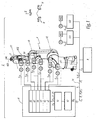
- an automated working cell 2 comprises a robot arm 4, a device 6 for controlling the robot arm 4, a control unit 8 and two electrical actuators partially shown.
- the robot arm 4 is constituted by a robotic arm with six axes referenced A1 to A6.
- the term "axis" is here used in the robotic sense, that is to say relates to a degree of freedom. In this case, the degrees of freedom or axes A1 to A6 are rotations.
- the robot control device 6 is disposed near the robot arm 4 and comprises six motor controllers 61 to 66. Each of these motor controllers 61 to 66 is adapted to control the operation of a motor M1 to M6 capable of Maneuver a part of the robot arm 4.
- the actuation of the motor M1 allows the entire rotation of the portion of the robot arm 4 located between the axis A1 and the movable end of the robot arm 4 without any other axis rotating on itself.
- the actuation of the motors M2, M3, M4 and M6 respectively allow the isolated rotation of the axes A2, A3, A4 and A6.
- the actuation of the motor M5 results in the rotation of the axes A5 and A6.
- There is a coupling between the axes A5 and A6 and an isolated rotation of the axis A5 requires the actuation of the motors M5 and M6.
- Each of the motors M1 to M6 is equipped with an encoder 12 placed on the motor shaft, making it possible to measure the angular position of the motor shaft and to deliver an electric signal S 12i , for i integer between 1 and 6, containing the information of this positon.
- Each of the two electric actuators is operated by an engine M21 and M22, each of these engines being respectively driven by an axis controller 121 and 122 and associated with an encoder 12 which delivers a position signal S 1221 or S 1222 .
- control unit 8 controls the operation of the automated cell 2 from programs 30 created by users for performing specific actions, such as for example the assembly of an object requiring movements of the robot arm 4 and possible actions of a gripper or a conveyor which includes the electric actuators operated by the M21 and M22 engines.
- programs may contain sequences of Cartesian coordinates to be reached by the end of the robot arm 4.
- the actions can be decided in real time by the user from a fixed or portable control panel 32 accessible to the user or the programmer of the automated work cell 2.
- the control unit 8 communicates with the control device 6 via a fieldbus 14, preferably operating on the SERCOS III serial real-time interface model.
- the control unit 8 is "master" while the control device 6 is “slave”.
- the control device 6 comprises a communication card 60 dedicated to the communication with the control unit 8 via the fieldbus 14.
- the control device 6 also comprises a calculation unit 10, whose function is to ensure the development and transmission of instructions such as orders of movement or power to the motor controllers 61 to 66.
- the computing unit 10 includes in particular for this purpose microprocessors and memories.
- the calculation unit 10 is adapted to communicate with each of the motor controllers 61 to 66. In this way, each data transmission between the motor controllers 61 to 66 and the control unit 8 is managed by the calculation unit. 10, from the motor controllers to the control panel and from the control panel to the motor controllers.
- the control axes of the robot arm 4 are chosen as the axes A1 to A6 which correspond to the degrees of freedom of the robot arm 4.
- each axis A1 to A6 of the robot arm 4 is associated with a dummy axis controller.
- These fictitious axis controllers are supposed to receive instructions from the control unit 8, in the same way as generic axis controllers and control at least one motor based on these instructions. They are declared as compliant with the "Profile drive” hardware profile that defines a set of commands for configuration, control, interrogation of states and positions, diagnosis and supervision.
- the instructions developed by the control unit 8 on the basis of the commands associated with the "Profile drive” hardware profile and usable by the imaginary axis controllers are received by the calculation unit 10.
- Each imaginary axis controller is seen assign an address in the same way as the two axis controllers 121 and 122 which control the actuators outside the robot arm 4 and present in the automated work cell 2.
- the control method according to the invention applies to the power-up phase of all the motors of the robot arm 4 prior to any operation of the robot arm of the automated work cell 2.
- This power-up is initiated by the control unit 8 which transmits on the bus 14 one or more master data telegrams with setpoints C oi , with i between 1 and 6, of energizing each of the axes A1 to A6.
- the communication card 60 of the control device 6 captures these telegrams. It then sends interrupt requests to the computing unit 10 which retrieves these telegrams, extracts the instructions C oi for each of the axes A1 to A6 of the robot arm 4 and proceeds to their processing.
- the SERCOS III interfacing protocol provides that each of the devices connected to the bus 14 is instructed to locate the data concerning it in a master data telegram.
- the calculation unit 10 records the power-on instructions and sends a response telegram to the control unit 8 in which the axes concerned by the setpoint are declared to be powered up.
- the motors are not really energized and the brakes are released until after the last power-up command is issued by the control unit 8.
- Power-up commands O 2i with i between 1 and 6, for each motor M1 to M6 are sent by the calculation unit 10 to each motor controller 61 to 66.
- the power-up commands of the motors M1 to M6 of the axes A1 to A6 of the robot arm 4 are similar to those of energizing the other motors M21 and M22 implemented in the automated cell 2 since the axes of the robot arm 4 and the other two axes are known to the control unit 8 as conforming to the "Profile drive" hardware profile. Since the computing unit 10 considers all the instructions for each of the axes A1 to A6 of the robot arm 4 to manage the powering up of the various motors, the programming of the control unit 8 is simplified.
- the control unit 8 executes an operating program 30 which contains motion commands that the robot must execute.
- the movement setpoints C 1i , with i between 1 and 6 for each axis A1 to A6 associated with a fictitious axis controller of the robot arm 4 are calculated by a trajectory generator 34 which implements an inverse geometric model 36 when the motion commands of the robot arm 4 express the Cartesian coordinates of a displacement of its end.
- all the setpoints C 1 1 , of axis movements are sent on the bus in the form of a master data telegram T 1 (C 1 i ). .
- the communication card 60 receives this telegram. It then sends a request for interruption to the computing unit 10 which retrieves the telegram, extracts the instructions C 1i from axis movements and proceeds to their processing.
- the calculation unit 10 calculates movement orders O 1i , with i between 1 and 6, for each of the motors M1 to M6 driven by the motor controllers 61 to 66.
- the movement commands O 1i for each of the motors are calculated from the set of setpoints C 1i received from the control unit 8 by applying the kinematic model of the transmissions 38. These orders include the positions to be reached for the engines.
- the calculation then takes into account the coupling existing between the axis A5 and the axis A6, the movement of the axis A5 requiring the implementation of the motors M5 and M6.
- the calculation of the O 1i motion commands for each motor also takes into account the reduction ratios between the motors and the robot rotation axes.
- the movement orders O 1i for each motor M1 to M6 are transmitted to the motor controller 61 to 66 of each of the motors which are responsible for determining and regulating the power supply current of the motor phases.
- the angular position of the shafts of each motor is detected thanks to the encoder 12 placed on the shaft of each motor.
- This information transmitted to each motor controller in the form of signals S 121 to S 126 enables servo-control 48 of the phase supply current of the motors.
- the calculation unit 10 also has through its connections with the motor controllers 61-66 of the angular position of the shafts of each motor of the robot arm 4 and calculates the angular positions P i, with i being an integer between 1 and 6 , moving parts around the axes A1 to A6 of the robot arm 4 by applying a model inverse kinematics of the transmissions 40. Due to the coupling of the axes A5 and A6, the angular positions of the shafts of the motors M5 and M6 intervene in the determination of the angular position P 6 of the axis A6. The calculation unit 10 can also, from the measurements, calculate the rotational speeds of the moving parts around the axes of the robot, the torques provided during these movements, or any other useful data.
- the calculation unit 10 of the robot generates a data telegram T ' 1 which contains the angular positions P i of the axes of the robot arm 4 and transmits it to the control unit 8 through the communication card 60.
- This information can then be used by the program 30 which governs the operation of the automated cell 2.
- the control unit 8 can apply a direct geometric model 42 to obtain for example the Cartesian position P c of the end of the robot arm 4 which can then be displayed on the control panel 32.
- the calculation unit 10 can calculate the Cartesian position of at least one characteristic point B, for example located on a tool flange 400 at the end of the robot arm 4, from the angular positions P i , with i integer between 1 and 6, moving parts about the axes A1 to A6 of the robot arm 4 and deduce the Cartesian velocity V (B) of this characteristic point.
- a comparison with a predefined threshold is made at the level of the calculation unit 10. If the Cartesian speed value V (B) of this characteristic point B is greater than this threshold, the calculation unit 10 issues a control stopping at all motor controllers 61 to 66 and sends to the control unit 8 a telegram to signal the error.
- the calculation unit 10 calculates the Cartesian velocity V (B) of the characteristic point from the movement setpoints C 1i , with i between 1 and 6 for each axis A1 to A6 associated with a hypothetical axis controller of the robot arm 4.
- the behavior of the robot arm 4 is substantially improved if the servocontrol of each motor takes into account a prediction of the torque F i , with i between 1 and 6, applied to the joints due to gravity or inertia forces.
- This torque prediction F i is established for each motor of the robot arm 4 at the level of the computing unit 10 which implements a dynamic model 44.
- the dynamic model is based on the knowledge of the motion commands C 1i of each axis which makes it possible to evaluate the accelerations required at each part of the robot arm 4.
- the prediction of the torque F i on the shaft of each motor of the robot arm 4 must take into account the movement instructions C 1i of all the axes A1 to A6.
- the torque prediction F i is translated into a current setpoint by applying the data or "constants" 46 of the motors and transmitted to the motor controllers 61 to 66 to be incorporated into the input of the control loops 50 of the power supply currents of the motor phases.
- the computation of the prediction of the torque F i to be provided at each articulation may also use the angular positions P i of the axes of the robot arm 4.
- the prediction of the torque F i with i between 1 and 6, applied to the joints and all the more precisely that it takes into account the loads to be transported by the robot arm 4.
- Each load is characterized by a mass, the position its center of gravity and its matrix of inertia but also the degree of freedom to which it is attached.
- the programmer of the control unit 8 can declare the transported loads with respect to each motion control axis of the robot arm 4. For example, for a load transported at the tool flange 400, it will report a load to through the controls dedicated to the A6 control axis. For a load transported at the forearm 402, it will declare a load through the commands dedicated to the control axis A4.
- These transported load declarations can be done asynchronously, that is to say outside the cyclic communication between the central control unit 8 and the calculation unit 10. They can also be done synchronously, which can be done synchronously. makes it possible to vary the load transported with each command sent by the control unit 8 and to adapt the control of the robot arm 4 to a sequence of movements during which the robot arm would capture and transport a load before releasing it and undertake another trip.
- the method according to the invention makes it possible to take into account the loads transported at the level of the calculation unit 10 so as to simplify the formation of the control unit 8.
- the method according to the invention also makes it possible to improve the accuracy of the trajectory of an unrepresented tool placed at the end of the robot arm 4 by taking into account the deformations of the robot arm under the effect of the load. These deformations can result from the flexibility of structural elements such as arms or transmission elements such as belts or reducers. From the motion instructions of each axis, the dynamic model 44 predicts each pair F i , with i between 1 and 6, applied to the joints due to gravity and inertia forces. These pairs F i make it possible to obtain, by applying a flexibility matrix specific to the robot arm 4, the articular deviations ⁇ i, with i between 1 and 6, due to the deformations.
- the articular deviations ⁇ i making it possible to compensate for the deformations of the robot arm 4, and are then added to the movement instructions of each axis and therefore taken into account in the calculation of the movement orders O 1i , with i between 1 and 6, for each of the motors M1 to M6 driven by the motor controllers 61 to 66.
- the calculation of the articular deviations ⁇ i can be established by taking into account only the part of the pairs Fi corresponding to the gravity, that is to say to the static forces.
- the method according to the invention also takes into account the possible malfunctions of each part of the robot 4.
- the calculation unit 10 of the control device 6 of the robot arm 4 supervises the operation of all the motor controllers. 61 to 66. It implements software that can detect malfunctions in motor controllers 61 to 66, motors M1 to M6 or encoders 12.
- the calculation unit 10 stops all the other motors of the robot arm 4 and controls the transmission, to the control unit 8, of a data telegram T 2 in which not only the axis whose rotation is normally allowed by the engine in question is declared as being in malfunction, but also all the axes of the robot arm 4.
- a malfunction on one of the axes of the 4 th robot arm the declaration of the impossibility of functioning of the entire robot arm. This information is sent to the control unit 8.
- control unit 8 Since the control unit 8 does not have to manage the defaulting of all the axes of the robot, its programming is simplified. This makes it possible to avoid communication between each motor controller 61 to 66 and the control unit 8, which speeds up the processing of faults and improves the securing of the robot arm 4.
- the computing unit 10 ensures the consistency of the behavior of the robot arm 4 in the event of a fault on one of the axes A1 to A6. It is the same when switching off one of the axes of the robot arm 4.
- Each of the motors M1 to M6 must then necessarily be de-energized.
- the shutdown of an engine must be preceded by the tightening of brakes to stop the rotation of the motors.
- the instruction to switch off the robot arm 4 from the control unit 8 is applied by the calculation unit 10 to each of the motor controllers.
- the unit computing circuit 10 then sends to each motor controller 61 to 66 an order O ' i , with i between 1 and 6, de-energizing the motors M1 to M6.
- the computing unit 10 ensures that the shafts of each of the motors of the robot arm 4 are braked well to avoid any accident.
- the calculation unit 10 transmits a telegram T 3 specifying to the control unit 8 that all the axes Ai, with i integer between 1 and 6, of the robot arm 4 have been turned off. voltage.
- the method of the invention makes it possible to improve the synchronization of the movements managed by the control unit 8. It is based on a client-server communication model in which the control unit 8 is the server.
- the bus 14 allows a synchronous communication mode.
- the communication between the control unit 8 and the control device 6 of the robot arm 4 via the bus 14 is at a frequency, called the communication frequency, the value of which is adapted to the number of devices, such as the motor controllers, to order.
- the computing unit 10 operates at a frequency, called the control frequency, whose value is higher than that of the communication frequency.
- the servocontrol performed within a motor controller 61 to 66 is at a frequency, called servo frequency, whose value is higher than that of the control frequency. Interpolation calculations are therefore required between each motion order transmission O 1i for the motors of the computing unit 10 to the motor controller. These calculations are performed within each motor controller 61 to 66.
- the operating program of the automated work cell 2 implemented by the control unit 8 generates instructions C 1i and requires knowledge of the angular positions P i of the axes of the robot arm 4.
- the control unit 8 requests the angular positions of each of the axes of the robot arm 4.
- the calculation unit 10 has the positions of the shafts of each motor with the encoders 12. They come from the motor controllers 61 to 66 and it enable the angular positions P i of the axes of the robot arm 4 to be calculated by applying the inverse kinematic model of the transmissions 40.
- the calculation unit 10 dates the angular position information from the motor controllers 61 to 66.
- the measurement of the angular position of the motor shaft detected by the encoders 12 is therefore associated with a measurement date.
- the computing unit 10 knows when it will have to. transmit the angular position values P i of the axes of the robot arm 4 at the request of the control unit 8. They are then corrected according to the measurement date, depending on the presumed movement of the arm of the robot 4 at the time of the measurement and the time interval separating the measurement date from the date of transmission with the control unit 8.
- the calculation unit 10 performs a synchronization.
- the method according to the invention can be implemented with a CAN bus (Controller area network) which integrates a CANopen application layer. It is also compatible with Powerlink and EtherCAT communication protocols.
- CAN bus Controller area network
- Powerlink and EtherCAT communication protocols are also compatible with Powerlink and EtherCAT communication protocols.
- the motion control axes of the robot arm 4 are chosen as being the Cartesian axes X, Y, Z, and the corresponding rotations Rx, Ry, Rz instead of the axes A1 to A6 of the robot arm 4.
- the programmer of the control unit 8 then expresses the desired displacements of the end of the robot arm 4 in 3 directions X, Y and Z and the orientation of the end of the robot arm 4 according to the rotations Rx, Ry and Rz about the X, Y and Z axes.
- the control unit 8 transmits to the control device 6 of the robot arm 4 Cartesian positions to reach.
- the calculation unit 10 incorporates the inverse geometrical model of the robot arm 4 and uses it to determine the displacement instructions intended for the motor controllers 61 to 66. Similarly, the calculation unit 10 incorporates and implements the direct geometrical model which makes it possible to calculate before transmitting to the control unit 8 the positions of the axes of motion control X, Y, Z, and the corresponding rotations Rx, Ry, Rz from the angular positions of the trees of each robot arm motor 4.
- the invention is not limited to the use of a robot with 6 degrees of freedom and can be applied for example to robots with 7 degrees of freedom.
- the programmer can advantageously choose as axes of motion control the Cartesian axes X, Y, Z, and the corresponding rotations Rx, Ry, Rz of movement of the end of the robot arm.
- the computing unit of the control device of the robot arm will implement the sophisticated inverse geometric model for solving the redundancies.
- the invention has been described with a control device of the robot 6 which comprises a communication card 60, a calculation unit 10 and motor controllers 61 to 66.
- the calculation unit 10 is able to process the information coming from of the control unit 8 and generate displacement instructions to the motor controllers 61 to 66.
- These motor controllers 61 to 66 are functionally comparable to conventional axis controllers such as the axis controllers 121 and 122. They receive position instructions and provide slave control of the currents that supply the phases of the electric actuators.
- the invention also applies to a structure which implements a calculation unit directly capable of generating the current setpoints for unrepresented power cards. These power cards are able to control the currents flowing in the phases of one or more electric actuators.
- the invention is not limited by the structure of the control device 6 of the robot arm 4.
- the orders for each of the motors M1 to M6 driven by an engine controller are determined from several, and not from the set, of the setpoints C 1i , with i integer between 1 and 6, received from the control unit 8.
Landscapes
- Engineering & Computer Science (AREA)
- Automation & Control Theory (AREA)
- Physics & Mathematics (AREA)
- Mechanical Engineering (AREA)
- Robotics (AREA)
- Human Computer Interaction (AREA)
- Manufacturing & Machinery (AREA)
- General Physics & Mathematics (AREA)
- Evolutionary Computation (AREA)
- Fuzzy Systems (AREA)
- Mathematical Physics (AREA)
- Software Systems (AREA)
- Artificial Intelligence (AREA)
- Manipulator (AREA)
- Numerical Control (AREA)
Priority Applications (1)
| Application Number | Priority Date | Filing Date | Title |
|---|---|---|---|
| PL11725169T PL2569129T5 (pl) | 2010-05-14 | 2011-05-13 | Sposób sterowania zautomatyzowaną komórką roboczą |
Applications Claiming Priority (2)
| Application Number | Priority Date | Filing Date | Title |
|---|---|---|---|
| FR1053771A FR2960075B1 (fr) | 2010-05-14 | 2010-05-14 | Procede de commande d'une cellule de travail automatisee |
| PCT/FR2011/051078 WO2011141684A1 (fr) | 2010-05-14 | 2011-05-13 | Procédé de commande d'une cellule de travail automatisée |
Publications (3)
| Publication Number | Publication Date |
|---|---|
| EP2569129A1 EP2569129A1 (fr) | 2013-03-20 |
| EP2569129B1 EP2569129B1 (fr) | 2014-04-02 |
| EP2569129B2 true EP2569129B2 (fr) | 2017-07-26 |
Family
ID=42674642
Family Applications (1)
| Application Number | Title | Priority Date | Filing Date |
|---|---|---|---|
| EP11725169.4A Active EP2569129B2 (fr) | 2010-05-14 | 2011-05-13 | Procédé de commande d'une cellule de travail automatisée |
Country Status (10)
| Country | Link |
|---|---|
| US (1) | US8965574B2 (pl) |
| EP (1) | EP2569129B2 (pl) |
| JP (1) | JP5916716B2 (pl) |
| KR (1) | KR101818570B1 (pl) |
| CN (1) | CN103025491B (pl) |
| DK (1) | DK2569129T4 (pl) |
| ES (1) | ES2458429T5 (pl) |
| FR (1) | FR2960075B1 (pl) |
| PL (1) | PL2569129T5 (pl) |
| WO (1) | WO2011141684A1 (pl) |
Families Citing this family (35)
| Publication number | Priority date | Publication date | Assignee | Title |
|---|---|---|---|---|
| FR2960074B1 (fr) * | 2010-05-14 | 2012-06-15 | Staubli Sa Ets | Procede de commande d'une cellule de travail automatisee |
| US20150314454A1 (en) * | 2013-03-15 | 2015-11-05 | JIBO, Inc. | Apparatus and methods for providing a persistent companion device |
| CN103831821B (zh) * | 2014-03-26 | 2015-08-19 | 哈尔滨工业大学 | 七自由度重载移动操作臂 |
| KR101661599B1 (ko) * | 2014-08-20 | 2016-10-04 | 한국과학기술연구원 | 하드웨어 한계를 고려하는 동작 데이터의 압축 및 복원을 이용한 로봇 동작 데이터 처리 시스템 |
| KR20160057635A (ko) | 2014-11-14 | 2016-05-24 | 롯데케미칼 주식회사 | 폴리카보네이트계 열가소성 수지 조성물 및 이를 이용한 제품 |
| WO2016125398A1 (ja) * | 2015-02-03 | 2016-08-11 | オリンパス株式会社 | 医療用マニピュレータシステムとその制御方法 |
| JP1568671S (pl) * | 2015-10-08 | 2017-02-06 | ||
| JP6096874B1 (ja) * | 2015-12-21 | 2017-03-15 | ファナック株式会社 | セルコントロールシステムにおける製造セルの状態変化管理システム |
| JP1582721S (pl) * | 2016-09-29 | 2017-07-31 | ||
| FR3063667B1 (fr) | 2017-03-13 | 2019-04-19 | Staubli Faverges | Procede de commande d'une cellule de travail automatisee |
| JP6724831B2 (ja) * | 2017-03-16 | 2020-07-15 | 株式会社安川電機 | コントロールシステム、コントローラ及び制御方法 |
| USD831087S1 (en) | 2017-03-23 | 2018-10-16 | Denso Wave Incorporated | Industrial robot |
| TWD194653S (zh) * | 2017-04-23 | 2018-12-11 | 德商法蘭卡愛米卡有限責任公司 | 工業機器人 |
| US10252420B2 (en) * | 2017-06-09 | 2019-04-09 | Precise Automation, Inc. | Collaborative robot |
| US10173323B2 (en) * | 2017-06-09 | 2019-01-08 | Precise Automation, Inc. | Collaborative robot |
| JP1611705S (pl) * | 2017-07-13 | 2018-08-20 | ||
| JP1598672S (pl) * | 2017-07-24 | 2018-03-05 | ||
| JP1599085S (pl) * | 2017-07-24 | 2018-03-05 | ||
| JP1612623S (pl) * | 2017-09-26 | 2018-09-03 | ||
| USD839941S1 (en) * | 2017-09-28 | 2019-02-05 | Abb Schweiz Ag | Industrial robot |
| USD870169S1 (en) * | 2017-11-22 | 2019-12-17 | Mitsubishi Electric Corporation | Industrial robot |
| JP1606240S (pl) * | 2017-11-22 | 2018-06-11 | ||
| JP1606239S (pl) * | 2017-11-22 | 2018-06-11 | ||
| USD865828S1 (en) * | 2018-03-21 | 2019-11-05 | Productive Robotics, Inc. | Manufacturing robot |
| FR3097565B1 (fr) * | 2019-06-19 | 2022-08-12 | Staubli Sa Ets | Machine textile, métier à tisser comportant une telle machine textile et procédés associés |
| US11554490B2 (en) | 2020-12-09 | 2023-01-17 | Robert Bosch Gmbh | Monitoring real-time data of a robotic manipulator |
| DE102021109904A1 (de) * | 2021-04-20 | 2022-10-20 | J. Schmalz Gmbh | Handhabungsvorrichtung mit definierter Ruhekonfiguration |
| USD1020828S1 (en) * | 2022-03-31 | 2024-04-02 | Agile Robots AG | Robotic arm for medical and industrial purposes |
| USD1033501S1 (en) * | 2022-08-10 | 2024-07-02 | Boston Dynamics, Inc. | Robotic device |
| USD1034728S1 (en) * | 2022-08-10 | 2024-07-09 | Boston Dynamics, Inc. | Robotic device |
| JP2024054794A (ja) * | 2022-10-05 | 2024-04-17 | 株式会社安川電機 | 搬送ロボット |
| USD1102503S1 (en) * | 2023-06-16 | 2025-11-18 | Agile Robots AG | Robotic arm link |
| USD1061654S1 (en) * | 2023-06-16 | 2025-02-11 | Agile Robots AG | Robotic arm |
| USD1062821S1 (en) * | 2023-06-26 | 2025-02-18 | Abb Schweiz Ag | Robot for preparing food or drink |
| USD1104095S1 (en) * | 2023-11-22 | 2025-12-02 | Guangdong Huayan Robotics Co., Ltd. | Collaborative robot |
Family Cites Families (21)
| Publication number | Priority date | Publication date | Assignee | Title |
|---|---|---|---|---|
| JPS5927308A (ja) * | 1982-08-02 | 1984-02-13 | Fanuc Ltd | セル制御システム |
| DE3782795T2 (de) * | 1986-09-29 | 1993-06-09 | Asea Ab | Verfahren und vorrichtung zur optimalen parameterregelung von reglern, die rotierende und/oder lineare bewegungen eines industrieroboters steuern. |
| JPH0760335B2 (ja) * | 1988-03-22 | 1995-06-28 | 横河電機株式会社 | ロボットの制御装置 |
| JP3401971B2 (ja) * | 1995-01-30 | 2003-04-28 | 松下電器産業株式会社 | デジタルサーボ装置 |
| JPH10254524A (ja) * | 1997-03-10 | 1998-09-25 | Fanuc Ltd | 機械の制御装置におけるユニット間通信方法 |
| DE19727824C1 (de) * | 1997-06-30 | 1998-11-19 | Siemens Ag | Verfahren und Vorrichtung zum dezentralen Betrieb bzw. Aufbau einer autarken, winkelgenauen Gleichlaufregelung einzelner Antriebe eines vernetzten Mehrmotorenantriebssystems |
| JPH1177573A (ja) * | 1997-09-02 | 1999-03-23 | Denso Corp | ロボット制御装置 |
| EP1015944B1 (en) * | 1997-09-19 | 2013-02-27 | Massachusetts Institute Of Technology | Surgical robotic apparatus |
| JP2000066706A (ja) | 1998-08-21 | 2000-03-03 | Matsushita Electric Ind Co Ltd | ロボット制御装置とその制御方法 |
| CN2447131Y (zh) * | 2000-09-30 | 2001-09-12 | 中国科学院自动化研究所 | 开放式工业机器人控制平台 |
| WO2003017019A1 (fr) * | 2001-08-02 | 2003-02-27 | Mitsubishi Denki Kabushiki Kaisha | Systeme de servocommande et procede de commande correspondant |
| US7457698B2 (en) * | 2001-08-31 | 2008-11-25 | The Board Of Regents Of The University And Community College System On Behalf Of The University Of Nevada, Reno | Coordinated joint motion control system |
| FR2850600B1 (fr) * | 2003-02-04 | 2006-01-13 | Staubli Sa Ets | Robot multi-axes equipe d'un systeme de commande |
| CN1309536C (zh) * | 2004-07-29 | 2007-04-11 | 上海交通大学 | 基于分布式控制的即插即用机械臂系统 |
| WO2006062948A2 (en) * | 2004-12-06 | 2006-06-15 | Honda Motor Co., Ltd. | Interface for robot motion control |
| WO2006062648A2 (en) | 2004-12-09 | 2006-06-15 | Jorge Perelman | A new material for making outer wrapping material by laminating a web material with a base material |
| CN101045297A (zh) | 2007-04-12 | 2007-10-03 | 武汉科技大学 | 一种分布式多自由度机器人控制系统 |
| JP2010058256A (ja) * | 2008-09-08 | 2010-03-18 | Yaskawa Electric Corp | アーム位置調整方法及び装置並びにロボットシステム |
| US20110106285A1 (en) * | 2009-11-02 | 2011-05-05 | Mold-Masters (2007) Limited | System for use in performance of injection molding operations |
| US8280544B2 (en) * | 2009-11-02 | 2012-10-02 | Mold Masters (2007) Limited | System for use in performance of injection molding operations |
| FR2960074B1 (fr) * | 2010-05-14 | 2012-06-15 | Staubli Sa Ets | Procede de commande d'une cellule de travail automatisee |
-
2010
- 2010-05-14 FR FR1053771A patent/FR2960075B1/fr active Active
-
2011
- 2011-05-13 JP JP2013509605A patent/JP5916716B2/ja active Active
- 2011-05-13 US US13/696,739 patent/US8965574B2/en active Active
- 2011-05-13 WO PCT/FR2011/051078 patent/WO2011141684A1/fr not_active Ceased
- 2011-05-13 CN CN201180034711.5A patent/CN103025491B/zh active Active
- 2011-05-13 PL PL11725169T patent/PL2569129T5/pl unknown
- 2011-05-13 KR KR1020127031213A patent/KR101818570B1/ko active Active
- 2011-05-13 ES ES11725169.4T patent/ES2458429T5/es active Active
- 2011-05-13 DK DK11725169.4T patent/DK2569129T4/en active
- 2011-05-13 EP EP11725169.4A patent/EP2569129B2/fr active Active
Also Published As
| Publication number | Publication date |
|---|---|
| CN103025491B (zh) | 2016-02-24 |
| ES2458429T5 (es) | 2017-11-20 |
| KR101818570B1 (ko) | 2018-01-15 |
| WO2011141684A1 (fr) | 2011-11-17 |
| JP2013526419A (ja) | 2013-06-24 |
| PL2569129T3 (pl) | 2014-09-30 |
| ES2458429T3 (es) | 2014-05-05 |
| JP5916716B2 (ja) | 2016-05-11 |
| FR2960075B1 (fr) | 2012-06-15 |
| US8965574B2 (en) | 2015-02-24 |
| DK2569129T4 (en) | 2017-09-25 |
| EP2569129A1 (fr) | 2013-03-20 |
| PL2569129T5 (pl) | 2018-02-28 |
| CN103025491A (zh) | 2013-04-03 |
| FR2960075A1 (fr) | 2011-11-18 |
| EP2569129B1 (fr) | 2014-04-02 |
| DK2569129T3 (da) | 2014-04-22 |
| KR20130095189A (ko) | 2013-08-27 |
| US20130116821A1 (en) | 2013-05-09 |
Similar Documents
| Publication | Publication Date | Title |
|---|---|---|
| EP2569129B2 (fr) | Procédé de commande d'une cellule de travail automatisée | |
| EP2569130B2 (fr) | Procédé de commande d'une cellule de travail automatisée | |
| EP3213163B1 (en) | A client device for data acquisition and pre-processing of process-related mass data from at least one cnc machine or industrial robot | |
| JP6540166B2 (ja) | 制御装置 | |
| CN106502095A (zh) | 一种多工业机器人的协同控制方法 | |
| JP2007122748A (ja) | 技術的設備を作動させるためのプロセス制御システム | |
| EP3112095A1 (fr) | Procédé de commande d'une cellule de travail automatisée | |
| JP6299064B2 (ja) | 制御装置、制御方法、およびプログラム | |
| CN110456707A (zh) | 控制装置 | |
| FR2864266A1 (fr) | Procede et dispositif de commande des deplacements d'une partie mobile d'un robot multi-axes | |
| EP3375575A1 (fr) | Procédé de commande d'une cellule de travail automatisée | |
| FR3012112A1 (fr) | Procede de surveillance de fonctionnement d'un dispositif de pilotage d'aeronef et dispositif de pilotage d'aeronef ainsi surveille | |
| CN112276976A (zh) | 基于云控平台的功能机器人控制系统 | |
| US20180267504A1 (en) | Control system and method for operating a control system with real control and virtual control | |
| CN120085613A (zh) | 一种分布式部署的多轴控制系统 | |
| US11942883B2 (en) | Method of controlling a drive motor | |
| CN121552349A (zh) | 用于工业机器人的多联控制系统和控制方法 | |
| CN111830872A (zh) | 机器人的控制方法、装置、存储介质和处理器 |
Legal Events
| Date | Code | Title | Description |
|---|---|---|---|
| PUAI | Public reference made under article 153(3) epc to a published international application that has entered the european phase |
Free format text: ORIGINAL CODE: 0009012 |
|
| 17P | Request for examination filed |
Effective date: 20121116 |
|
| AK | Designated contracting states |
Kind code of ref document: A1 Designated state(s): AL AT BE BG CH CY CZ DE DK EE ES FI FR GB GR HR HU IE IS IT LI LT LU LV MC MK MT NL NO PL PT RO RS SE SI SK SM TR |
|
| DAX | Request for extension of the european patent (deleted) | ||
| GRAP | Despatch of communication of intention to grant a patent |
Free format text: ORIGINAL CODE: EPIDOSNIGR1 |
|
| INTG | Intention to grant announced |
Effective date: 20131025 |
|
| GRAS | Grant fee paid |
Free format text: ORIGINAL CODE: EPIDOSNIGR3 |
|
| GRAA | (expected) grant |
Free format text: ORIGINAL CODE: 0009210 |
|
| AK | Designated contracting states |
Kind code of ref document: B1 Designated state(s): AL AT BE BG CH CY CZ DE DK EE ES FI FR GB GR HR HU IE IS IT LI LT LU LV MC MK MT NL NO PL PT RO RS SE SI SK SM TR |
|
| REG | Reference to a national code |
Ref country code: GB Ref legal event code: FG4D Free format text: NOT ENGLISH |
|
| REG | Reference to a national code |
Ref country code: AT Ref legal event code: REF Ref document number: 659799 Country of ref document: AT Kind code of ref document: T Effective date: 20140415 Ref country code: CH Ref legal event code: EP |
|
| REG | Reference to a national code |
Ref country code: DK Ref legal event code: T3 Effective date: 20140411 Ref country code: SE Ref legal event code: TRGR |
|
| REG | Reference to a national code |
Ref country code: ES Ref legal event code: FG2A Ref document number: 2458429 Country of ref document: ES Kind code of ref document: T3 Effective date: 20140505 |
|
| REG | Reference to a national code |
Ref country code: IE Ref legal event code: FG4D Free format text: LANGUAGE OF EP DOCUMENT: FRENCH |
|
| REG | Reference to a national code |
Ref country code: DE Ref legal event code: R096 Ref document number: 602011005937 Country of ref document: DE Effective date: 20140515 |
|
| REG | Reference to a national code |
Ref country code: NL Ref legal event code: T3 |
|
| REG | Reference to a national code |
Ref country code: LT Ref legal event code: MG4D |
|
| REG | Reference to a national code |
Ref country code: PL Ref legal event code: T3 |
|
| REG | Reference to a national code |
Ref country code: HU Ref legal event code: AG4A Ref document number: E020651 Country of ref document: HU |
|
| PG25 | Lapsed in a contracting state [announced via postgrant information from national office to epo] |
Ref country code: CY Free format text: LAPSE BECAUSE OF FAILURE TO SUBMIT A TRANSLATION OF THE DESCRIPTION OR TO PAY THE FEE WITHIN THE PRESCRIBED TIME-LIMIT Effective date: 20140402 Ref country code: NO Free format text: LAPSE BECAUSE OF FAILURE TO SUBMIT A TRANSLATION OF THE DESCRIPTION OR TO PAY THE FEE WITHIN THE PRESCRIBED TIME-LIMIT Effective date: 20140702 Ref country code: BG Free format text: LAPSE BECAUSE OF FAILURE TO SUBMIT A TRANSLATION OF THE DESCRIPTION OR TO PAY THE FEE WITHIN THE PRESCRIBED TIME-LIMIT Effective date: 20140702 Ref country code: IS Free format text: LAPSE BECAUSE OF FAILURE TO SUBMIT A TRANSLATION OF THE DESCRIPTION OR TO PAY THE FEE WITHIN THE PRESCRIBED TIME-LIMIT Effective date: 20140802 Ref country code: LT Free format text: LAPSE BECAUSE OF FAILURE TO SUBMIT A TRANSLATION OF THE DESCRIPTION OR TO PAY THE FEE WITHIN THE PRESCRIBED TIME-LIMIT Effective date: 20140402 Ref country code: FI Free format text: LAPSE BECAUSE OF FAILURE TO SUBMIT A TRANSLATION OF THE DESCRIPTION OR TO PAY THE FEE WITHIN THE PRESCRIBED TIME-LIMIT Effective date: 20140402 Ref country code: GR Free format text: LAPSE BECAUSE OF FAILURE TO SUBMIT A TRANSLATION OF THE DESCRIPTION OR TO PAY THE FEE WITHIN THE PRESCRIBED TIME-LIMIT Effective date: 20140703 |
|
| PG25 | Lapsed in a contracting state [announced via postgrant information from national office to epo] |
Ref country code: HR Free format text: LAPSE BECAUSE OF FAILURE TO SUBMIT A TRANSLATION OF THE DESCRIPTION OR TO PAY THE FEE WITHIN THE PRESCRIBED TIME-LIMIT Effective date: 20140402 Ref country code: LV Free format text: LAPSE BECAUSE OF FAILURE TO SUBMIT A TRANSLATION OF THE DESCRIPTION OR TO PAY THE FEE WITHIN THE PRESCRIBED TIME-LIMIT Effective date: 20140402 Ref country code: RS Free format text: LAPSE BECAUSE OF FAILURE TO SUBMIT A TRANSLATION OF THE DESCRIPTION OR TO PAY THE FEE WITHIN THE PRESCRIBED TIME-LIMIT Effective date: 20140402 |
|
| REG | Reference to a national code |
Ref country code: DE Ref legal event code: R026 Ref document number: 602011005937 Country of ref document: DE |
|
| PLBI | Opposition filed |
Free format text: ORIGINAL CODE: 0009260 |
|
| PG25 | Lapsed in a contracting state [announced via postgrant information from national office to epo] |
Ref country code: PT Free format text: LAPSE BECAUSE OF FAILURE TO SUBMIT A TRANSLATION OF THE DESCRIPTION OR TO PAY THE FEE WITHIN THE PRESCRIBED TIME-LIMIT Effective date: 20140804 |
|
| 26 | Opposition filed |
Opponent name: DUERR SYSTEMS GMBH Effective date: 20141215 |
|
| PG25 | Lapsed in a contracting state [announced via postgrant information from national office to epo] |
Ref country code: RO Free format text: LAPSE BECAUSE OF FAILURE TO SUBMIT A TRANSLATION OF THE DESCRIPTION OR TO PAY THE FEE WITHIN THE PRESCRIBED TIME-LIMIT Effective date: 20140402 Ref country code: EE Free format text: LAPSE BECAUSE OF FAILURE TO SUBMIT A TRANSLATION OF THE DESCRIPTION OR TO PAY THE FEE WITHIN THE PRESCRIBED TIME-LIMIT Effective date: 20140402 Ref country code: MC Free format text: LAPSE BECAUSE OF FAILURE TO SUBMIT A TRANSLATION OF THE DESCRIPTION OR TO PAY THE FEE WITHIN THE PRESCRIBED TIME-LIMIT Effective date: 20140402 Ref country code: SK Free format text: LAPSE BECAUSE OF FAILURE TO SUBMIT A TRANSLATION OF THE DESCRIPTION OR TO PAY THE FEE WITHIN THE PRESCRIBED TIME-LIMIT Effective date: 20140402 |
|
| PLAX | Notice of opposition and request to file observation + time limit sent |
Free format text: ORIGINAL CODE: EPIDOSNOBS2 |
|
| REG | Reference to a national code |
Ref country code: IE Ref legal event code: MM4A |
|
| REG | Reference to a national code |
Ref country code: DE Ref legal event code: R026 Ref document number: 602011005937 Country of ref document: DE Effective date: 20141215 |
|
| PG25 | Lapsed in a contracting state [announced via postgrant information from national office to epo] |
Ref country code: IE Free format text: LAPSE BECAUSE OF NON-PAYMENT OF DUE FEES Effective date: 20140513 |
|
| PG25 | Lapsed in a contracting state [announced via postgrant information from national office to epo] |
Ref country code: RS Free format text: LAPSE BECAUSE OF FAILURE TO SUBMIT A TRANSLATION OF THE DESCRIPTION OR TO PAY THE FEE WITHIN THE PRESCRIBED TIME-LIMIT Effective date: 20141119 |
|
| PLAF | Information modified related to communication of a notice of opposition and request to file observations + time limit |
Free format text: ORIGINAL CODE: EPIDOSCOBS2 |
|
| PG25 | Lapsed in a contracting state [announced via postgrant information from national office to epo] |
Ref country code: SI Free format text: LAPSE BECAUSE OF FAILURE TO SUBMIT A TRANSLATION OF THE DESCRIPTION OR TO PAY THE FEE WITHIN THE PRESCRIBED TIME-LIMIT Effective date: 20140402 |
|
| PLBB | Reply of patent proprietor to notice(s) of opposition received |
Free format text: ORIGINAL CODE: EPIDOSNOBS3 |
|
| PG25 | Lapsed in a contracting state [announced via postgrant information from national office to epo] |
Ref country code: MT Free format text: LAPSE BECAUSE OF FAILURE TO SUBMIT A TRANSLATION OF THE DESCRIPTION OR TO PAY THE FEE WITHIN THE PRESCRIBED TIME-LIMIT Effective date: 20140402 |
|
| PG25 | Lapsed in a contracting state [announced via postgrant information from national office to epo] |
Ref country code: SM Free format text: LAPSE BECAUSE OF FAILURE TO SUBMIT A TRANSLATION OF THE DESCRIPTION OR TO PAY THE FEE WITHIN THE PRESCRIBED TIME-LIMIT Effective date: 20140402 |
|
| REG | Reference to a national code |
Ref country code: FR Ref legal event code: PLFP Year of fee payment: 6 |
|
| PG25 | Lapsed in a contracting state [announced via postgrant information from national office to epo] |
Ref country code: LU Free format text: LAPSE BECAUSE OF NON-PAYMENT OF DUE FEES Effective date: 20140513 |
|
| PLAB | Opposition data, opponent's data or that of the opponent's representative modified |
Free format text: ORIGINAL CODE: 0009299OPPO |
|
| PLBP | Opposition withdrawn |
Free format text: ORIGINAL CODE: 0009264 |
|
| R26 | Opposition filed (corrected) |
Opponent name: DUERR SYSTEMS AG Effective date: 20141215 |
|
| REG | Reference to a national code |
Ref country code: FR Ref legal event code: PLFP Year of fee payment: 7 |
|
| PUAH | Patent maintained in amended form |
Free format text: ORIGINAL CODE: 0009272 |
|
| STAA | Information on the status of an ep patent application or granted ep patent |
Free format text: STATUS: PATENT MAINTAINED AS AMENDED |
|
| 27A | Patent maintained in amended form |
Effective date: 20170726 |
|
| AK | Designated contracting states |
Kind code of ref document: B2 Designated state(s): AL AT BE BG CH CY CZ DE DK EE ES FI FR GB GR HR HU IE IS IT LI LT LU LV MC MK MT NL NO PL PT RO RS SE SI SK SM TR |
|
| REG | Reference to a national code |
Ref country code: DE Ref legal event code: R102 Ref document number: 602011005937 Country of ref document: DE |
|
| REG | Reference to a national code |
Ref country code: CH Ref legal event code: AELC |
|
| REG | Reference to a national code |
Ref country code: DK Ref legal event code: T4 Effective date: 20170920 |
|
| REG | Reference to a national code |
Ref country code: SE Ref legal event code: RPEO |
|
| REG | Reference to a national code |
Ref country code: NL Ref legal event code: FP |
|
| REG | Reference to a national code |
Ref country code: ES Ref legal event code: DC2A Ref document number: 2458429 Country of ref document: ES Kind code of ref document: T5 Effective date: 20171120 |
|
| REG | Reference to a national code |
Ref country code: FR Ref legal event code: PLFP Year of fee payment: 8 |
|
| PG25 | Lapsed in a contracting state [announced via postgrant information from national office to epo] |
Ref country code: MK Free format text: LAPSE BECAUSE OF FAILURE TO SUBMIT A TRANSLATION OF THE DESCRIPTION OR TO PAY THE FEE WITHIN THE PRESCRIBED TIME-LIMIT Effective date: 20140402 |
|
| PG25 | Lapsed in a contracting state [announced via postgrant information from national office to epo] |
Ref country code: AL Free format text: LAPSE BECAUSE OF FAILURE TO SUBMIT A TRANSLATION OF THE DESCRIPTION OR TO PAY THE FEE WITHIN THE PRESCRIBED TIME-LIMIT Effective date: 20140402 |
|
| REG | Reference to a national code |
Ref country code: AT Ref legal event code: UEP Ref document number: 659799 Country of ref document: AT Kind code of ref document: T Effective date: 20170726 |
|
| P01 | Opt-out of the competence of the unified patent court (upc) registered |
Effective date: 20230509 |
|
| PGFP | Annual fee paid to national office [announced via postgrant information from national office to epo] |
Ref country code: NL Payment date: 20250526 Year of fee payment: 15 |
|
| PGFP | Annual fee paid to national office [announced via postgrant information from national office to epo] |
Ref country code: PL Payment date: 20250418 Year of fee payment: 15 Ref country code: DE Payment date: 20250529 Year of fee payment: 15 |
|
| PGFP | Annual fee paid to national office [announced via postgrant information from national office to epo] |
Ref country code: GB Payment date: 20250527 Year of fee payment: 15 Ref country code: ES Payment date: 20250602 Year of fee payment: 15 Ref country code: DK Payment date: 20250526 Year of fee payment: 15 |
|
| PGFP | Annual fee paid to national office [announced via postgrant information from national office to epo] |
Ref country code: HU Payment date: 20250425 Year of fee payment: 15 |
|
| PGFP | Annual fee paid to national office [announced via postgrant information from national office to epo] |
Ref country code: BE Payment date: 20250527 Year of fee payment: 15 Ref country code: IT Payment date: 20250521 Year of fee payment: 15 |
|
| PGFP | Annual fee paid to national office [announced via postgrant information from national office to epo] |
Ref country code: FR Payment date: 20250526 Year of fee payment: 15 |
|
| PGFP | Annual fee paid to national office [announced via postgrant information from national office to epo] |
Ref country code: CH Payment date: 20250601 Year of fee payment: 15 |
|
| PGFP | Annual fee paid to national office [announced via postgrant information from national office to epo] |
Ref country code: AT Payment date: 20250423 Year of fee payment: 15 |
|
| PGFP | Annual fee paid to national office [announced via postgrant information from national office to epo] |
Ref country code: TR Payment date: 20250428 Year of fee payment: 15 |
|
| PGFP | Annual fee paid to national office [announced via postgrant information from national office to epo] |
Ref country code: CZ Payment date: 20250425 Year of fee payment: 15 |
|
| PGFP | Annual fee paid to national office [announced via postgrant information from national office to epo] |
Ref country code: SE Payment date: 20250527 Year of fee payment: 15 |