EP2568490A2 - Abdeckung und Schalter damit - Google Patents
Abdeckung und Schalter damit Download PDFInfo
- Publication number
- EP2568490A2 EP2568490A2 EP12177299A EP12177299A EP2568490A2 EP 2568490 A2 EP2568490 A2 EP 2568490A2 EP 12177299 A EP12177299 A EP 12177299A EP 12177299 A EP12177299 A EP 12177299A EP 2568490 A2 EP2568490 A2 EP 2568490A2
- Authority
- EP
- European Patent Office
- Prior art keywords
- tubular
- elastic deformation
- cover
- tubular elastic
- operation shaft
- Prior art date
- Legal status (The legal status is an assumption and is not a legal conclusion. Google has not performed a legal analysis and makes no representation as to the accuracy of the status listed.)
- Granted
Links
Images



Classifications
-
- H—ELECTRICITY
- H01—ELECTRIC ELEMENTS
- H01H—ELECTRIC SWITCHES; RELAYS; SELECTORS; EMERGENCY PROTECTIVE DEVICES
- H01H13/00—Switches having rectilinearly-movable operating part or parts adapted for pushing or pulling in one direction only, e.g. push-button switch
- H01H13/02—Details
- H01H13/04—Cases; Covers
- H01H13/06—Dustproof, splashproof, drip-proof, waterproof or flameproof casings
-
- H—ELECTRICITY
- H01—ELECTRIC ELEMENTS
- H01H—ELECTRIC SWITCHES; RELAYS; SELECTORS; EMERGENCY PROTECTIVE DEVICES
- H01H13/00—Switches having rectilinearly-movable operating part or parts adapted for pushing or pulling in one direction only, e.g. push-button switch
- H01H13/02—Details
- H01H13/12—Movable parts; Contacts mounted thereon
- H01H13/14—Operating parts, e.g. push-button
- H01H13/18—Operating parts, e.g. push-button adapted for actuation at a limit or other predetermined position in the path of a body, the relative movement of switch and body being primarily for a purpose other than the actuation of the switch, e.g. door switch, limit switch, floor-levelling switch of a lift
-
- H—ELECTRICITY
- H01—ELECTRIC ELEMENTS
- H01H—ELECTRIC SWITCHES; RELAYS; SELECTORS; EMERGENCY PROTECTIVE DEVICES
- H01H9/00—Details of switching devices, not covered by groups H01H1/00 - H01H7/00
- H01H9/02—Bases, casings, or covers
- H01H9/04—Dustproof, splashproof, drip-proof, waterproof, or flameproof casings
-
- H—ELECTRICITY
- H01—ELECTRIC ELEMENTS
- H01H—ELECTRIC SWITCHES; RELAYS; SELECTORS; EMERGENCY PROTECTIVE DEVICES
- H01H9/00—Details of switching devices, not covered by groups H01H1/00 - H01H7/00
- H01H9/02—Bases, casings, or covers
- H01H9/04—Dustproof, splashproof, drip-proof, waterproof, or flameproof casings
- H01H9/041—Casings hermetically closed by a diaphragm through which passes an actuating member
-
- H—ELECTRICITY
- H01—ELECTRIC ELEMENTS
- H01H—ELECTRIC SWITCHES; RELAYS; SELECTORS; EMERGENCY PROTECTIVE DEVICES
- H01H9/00—Details of switching devices, not covered by groups H01H1/00 - H01H7/00
- H01H9/02—Bases, casings, or covers
- H01H9/04—Dustproof, splashproof, drip-proof, waterproof, or flameproof casings
- H01H2009/048—Dustproof, splashproof, drip-proof, waterproof, or flameproof casings using a sealing boot, e.g. the casing having separate elastic body surrounding the operating member and hermetically closing the opening for it
Definitions
- the present application relates to a water proof and/or dust proof cover for covering an outer circumferential surface of an operation shaft of a switch provided it the operation shaft operable in the axis direction such as a trigger switch, so as to prevent invasion of water, grit, and dust.
- a cover in order to cover an outer circumferential surface of an operation shaft so as to prevent invasion of grit and dust, for example, there is a dust cover to be installed to a movable portion of a limit switch, the dust cover for a limit switch for covering the entire movable portion including a main body of the limit switch, the dust cover having a zigzag portion with at least one peak or trough (refer to Japanese Unexamined Patent Publication No. 11-53979 ).
- the present application has been devised to solve the problems described above, and an object thereof is to provide a long-life cover whose outer circumferential edge is not warped upward and not easily damaged even when an operation shaft is pushed down to a final position.
- a cover for covering an operation shaft protruding from a housing of an electric device and being operable in an axis direction includes a tubular pressing portion to which a pressing force is applied by operating the operation shaft, and a tubular elastic deformation portion continuous with a lower edge of an outer circumference of the tubular pressing portion, the tubular elastic deformation portion being thinner than the tubular pressing portion.
- the thin tubular elastic deformation portion when the tubular pressing portion is pushed down, the thin tubular elastic deformation portion is firstly largely bent. Particularly, when the tubular pressing portion is pushed down, the thin tubular elastic deformation portion is bent inward so as to be covered by the tubular pressing portion, Therefore, an outer circumferential edge of the tubular pressing portion as in a conventional example is not warped upward and does not come out. As a result, since the outer circumferential edge of the tubular pressing portion is not easily worn out and not easily damaged, durability is improved, so that the long-life cover can be obtained.
- an annular groove portion forming a thin portion which is the thinnest part of the cover may be provided along an edge on the side of the tubular elastic deformation portion in a region where the lower edge of the tubular pressing portion and an upper edge of the tubular elastic deformation portion are connected.
- annular groove portion forming a thin portion which is the thinnest part of the cover may be provided along an edge on the side of the tubular elastic deformation portion placed on an inner surface in a region where the lower edge of the tubular pressing portion and an upper edge of the tubular elastic deformation portion are connected.
- annular groove portion forming a thin portion which is the thinnest part of the cover may be provided along an edge on the side of the tubular elastic deformation portion placed on an outer circumferential surface in a region where the lower edge of the tubular pressing portion and an upper edge of the tubular elastic deformation portion are connected.
- the further thinner thin portion is formed between the tubular pressing portion and the tubular elastic deformation portion. Therefore, when the tubular pressing portion is pushed down, the thinner thin portion is firstly elastically deformed, and then the tubular elastic deformation portion is deformed. Thus, a push-down operation can be smoothly performed, so that the cover with favorable operation feel can be obtained.
- At least one annular cutout portion may be provided along an outer circumferential surface of the tubular elastic deformation portion.
- at least one annular cutout portion may be provided along an inner circumferential surface of the tubular elastic deformation portion.
- a thin region is partially formed in the tubular elastic deformation portion by the annular cutout portion. Therefore, the tubular elastic deformation portion is easily bent along the annular cutout portion. Thus, the push-down operation can be smoothly performed, so that the cover with favorable operation feel can be obtained.
- a plurality of thick tubular pressing portions formed into a substantially truncated cone and a plurality of thin tubular elastic deformation portions formed into a substantially reversed truncated cone, the tubular elastic deformation portions being continuous to lower edges of outer of circumferences of the tubular pressing portions may be alternately provided in a zigzag shape.
- an operation hole from which a front end surface of the operation shaft is exposed may be provided in center of a front end surface of the tubular pressing portion.
- the thick tubular pressing portion is pushed down via the front end surface of the operation shaft, and the thin tubular elastic deformation portion is bent inward.
- the long-life cover can be obtained.
- the front end surface of the operation shaft is not always required to be exposed from the operation hole of the cover but the entire operation shaft may be covered by the cover.
- a switch in accordance with another aspect of the present application, includes an operation shaft protruding from a housing and being operable in an axis direction, and a cover for covering the operation shaft, wherein the cover includes a tubular pressing portion to which a pressing force is applied by operating the operation shaft, and a tubular elastic deformation portion continuous to a lower edge of an outer circumference of the tubular pressing portion, the tubular elastic deformation portion being thinner than the tubular pressing portion.
- the switch according to the present application when the tubular pressing portion is pushed down, the thin tubular elastic deformation portion is firstly largely bent. Particularly, when the tubular pressing portion is pushed down, the thin tubular elastic deformation portion is bent inward so as to be covered by the tubular pressing portion. Therefore, the outer circumferential edge of the tubular pressing portion as in the conventional example is not warped upward and does not come out. As a result, since the outer circumferential edge of the tubular pressing portion is not easily worn out and not easily damaged, durability is improved. Thus, there is an effect that the switch including the long-life cover can be obtained.
- Fig. 1A is a perspective view showing a trigger switch to which a cover is applied
- Fig. 1B is a perspective view showing the cover for the trigger switch shown in Fig. 1A ;
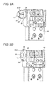
- Figs. 2A and 2B are perspective views showing states before and after the trigger switch shown in Fig. 1A is operated;
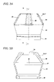
- Fig. 3A is a front view showing the cover shown in Fig. 1B
- Fig. 3B is a sectional view taken along line B-B of Fig. 3A ;
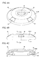
- Figs. 4A and 4B are a perspective view and a front view showing a state that the cover shown in Fig. 1B is elastically deformed, and Fig. 4C is a sectional view taken along line C-C of Fig. 4B ;
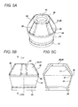
- Figs. 5A and 5B are a perspective view and a front view showing a second embodiment of the cover, and Fig. 5C is a sectional view taken along line C-C of Fig. 5B ;
- Figs. 6A and 6B are a perspective view and a front view showing a third embodiment of the cover, and Fig. 6C is a sectional view taken along line C-C of Fig. 6B ;
- Figs. 7A and 7B are a perspective view and a front view showing a fourth embodiment of the cover, and Fig. 7C is a sectional view taken along line C-C of Fig. 7B .
- a first embodiment is a dust proof cover 20 for covering an operation shaft 11 with a substantially T shape section attached to a switch main body 10 reciprocably in the axis direction as shown in Figs. 1A to 4C .
- the dust proof cover 20 is formed by a thick tubular pressing portion 21 formed into a substantially truncated cone, a thin tubular elastic deformation portion 22 formed into a substantially reversed truncated cone, the tubular elastic deformation portion being continuous with a lower edge of the tubular pressing portion 21, and an annular installment portion 23 continuous with a lower edge of the tubular elastic deformation portion 22.
- the tubular pressing portion 21 becomes gradually thinner from an upper end thereof to a lower end, and an operation hole 24 into which the operation shaft 11 can be inserted is provided in center of an upper end surface thereof, while reinforcing ribs 25 are integrally formed at a predetermined pitch on an outer circumferential surface thereof.
- the tubular elastic deformation portion 22 is thinner than the tubular pressing portion 21 and by providing an annular groove portion 26 along an edge on the side of the tubular elastic deformation portion 22 placed on an inner circumferential surface in a connection region with the tubular pressing portion 21, a thin portion 27 which is the thinnest part of the cover 20 is formed.
- the thin portion 27 is provided so as to easily bend the tubular elastic deformation portion 22 inward.
- the annular installment portion 23 is elastically deformed and installed so as to be closely attached to an attachment flange (not shown) protruding from a housing of the switch main bony 1 0.
- the cover 20 is elastically deformed so as to cover the operation shaft 11 with the T shape section attached to the switch main body 10, and the annular installment portion 23 is installed to the attachment flange of the switch main body 10.
- the cover 20 does not always require the operation hole 24 but may also cover the front end surface of the operation shaft 11.
- the reinforcing ribs 25 are not always required but may be provided according to need.
- a second embodiment is the substantially same as the first embodiment described above.
- the annular groove portion 26 is provided along an edge on the side of the tubular elastic deformation portion 22 placed on an outer circumferential surface in the region where the tubular pressing portion 21 and the tubular elastic deformation portion 22 are connected.
- the second embodiment is the same as the first embodiment.
- the same parts will be given the same reference numerals and description thereof will not be repeated.
- the annular groove portion 26 is formed on the outer circumferential surface.
- a third embodiment is the substantially same as the first embodiment described above.
- a different point is that no reinforcing ribs are provided on the outer circumferential surface of the tubular pressing portion 21 and the tubular pressing portion is thick and uniform, while annular cutout grooves 28 are provided at a predetermined pitch on the outer circumferential surface of the tubular elastic deformation portion 22.
- the third embodiment is the same as the first embodiment. Thus, the same parts will be given the same reference numerals and description thereof will not be repeated.
- the tubular elastic deformation portion 22 starts to be further bent inward along the annular cutout grooves 28. Therefore, there is an advantage that the tubular elastic deformation portion 22 is more smoothly deformed along the plurality of annular cutout grooves 28 provided in the tubular elastic deformation portion 22, and operation feel is improved.
- annular cutout grooves 28 may be provided along an inner circumferential surface of the tubular elastic deformation portion 22 as a matter of course.
- a fourth embodiment is a case where a plurality of tubular pressing portions 21 and a plurality of tubular elastic deformation portions 22 are alternately formed in a zigzag shape.
- the reinforcing ribs 25 are provided at a predetermined pitch on the outer circumferential surface of the tubular pressing portion 21.
- the fourth embodiment is the same as the above embodiments. Thus, the same parts will be given the same reference numerals and description thereof will not be repeated.
- the thin tubular elastic deformation portions 22 are elastically deformed inward, and the thick tubular pressing portions 21 are deformed so as to be piled on the thick tubular pressing portions 21 placed on the lower side. Therefore, the thin tubular elastic deformation portion 22 is not sandwiched by the thick tubular pressing portions 21, 21. As a result, there is an advantage that an elastic deformation amount of the entire cover 20 can be increased, and the cover applicable to the operation shaft having a large moving distance can be obtained.
- the present cover is not limited to this but may be applied to other switches such as a limit switch.
- the present cover is not limited to application to the dust proof cover but may be applied to a water proof cover.
- tubular pressing portion formed into a substantially truncated cone or the tubular elastic deformation portion formed into a substantially reversed truncated cone is a concept including six-sided truncated pyramid, eight-sided truncated pyramid, and twelve-sided truncated pyramid portions for example.
- the operation shaft is not always required to be exposed from the cover but the entire operation shaft may be covered by the cover.
Landscapes
- Push-Button Switches (AREA)
- Mechanisms For Operating Contacts (AREA)
- Switches With Compound Operations (AREA)
Applications Claiming Priority (1)
| Application Number | Priority Date | Filing Date | Title |
|---|---|---|---|
| JP2011198531A JP5824991B2 (ja) | 2011-09-12 | 2011-09-12 | カバーおよびこれを用いたスイッチ |
Publications (3)
| Publication Number | Publication Date |
|---|---|
| EP2568490A2 true EP2568490A2 (de) | 2013-03-13 |
| EP2568490A3 EP2568490A3 (de) | 2014-03-19 |
| EP2568490B1 EP2568490B1 (de) | 2017-04-05 |
Family
ID=46642359
Family Applications (1)
| Application Number | Title | Priority Date | Filing Date |
|---|---|---|---|
| EP12177299.0A Active EP2568490B1 (de) | 2011-09-12 | 2012-07-20 | Abdeckung und Schalter damit |
Country Status (4)
| Country | Link |
|---|---|
| US (1) | US20130062171A1 (de) |
| EP (1) | EP2568490B1 (de) |
| JP (1) | JP5824991B2 (de) |
| CN (1) | CN103151201B (de) |
Cited By (1)
| Publication number | Priority date | Publication date | Assignee | Title |
|---|---|---|---|---|
| US9984835B2 (en) * | 2016-09-01 | 2018-05-29 | Banner Engineering Corp. | Impact absorbing unitary cover assembly |
Families Citing this family (1)
| Publication number | Priority date | Publication date | Assignee | Title |
|---|---|---|---|---|
| CN105489424B (zh) * | 2014-10-10 | 2017-11-03 | 神讯电脑(昆山)有限公司 | 防水按钮总成 |
Citations (1)
| Publication number | Priority date | Publication date | Assignee | Title |
|---|---|---|---|---|
| JPH1153979A (ja) | 1997-08-01 | 1999-02-26 | Keeper Co Ltd | リミットスイッチ用ダストカバー |
Family Cites Families (12)
| Publication number | Priority date | Publication date | Assignee | Title |
|---|---|---|---|---|
| US3790734A (en) * | 1971-11-12 | 1974-02-05 | Indak Mfg Corp | Alternate action switch with sealing boot giving visual indication of switch position |
| US4298778A (en) * | 1979-01-25 | 1981-11-03 | Beresford Jones Godric P K | Waterproof seal for a push-button |
| GB2044002A (en) * | 1979-01-25 | 1980-10-08 | Beresford Jones G P K | Waterproof seal for a push- button |
| IT206270Z2 (it) * | 1985-10-09 | 1987-07-20 | Vimercati Off Mec | Interruttore stagno a pulsante |
| JPS639724U (de) * | 1986-07-07 | 1988-01-22 | ||
| US5063277A (en) * | 1989-06-28 | 1991-11-05 | Daiichi Denso Buhin Co., Ltd. | Waterproof and dustproof push switch |
| AU630757B2 (en) * | 1989-11-04 | 1992-11-05 | Yoshikazu Kuze | Tubular member for sealing a reciprocating rod |
| US5382767A (en) * | 1992-11-12 | 1995-01-17 | Daiichi Denso Buhin Co., Ltd. | Push-button switches |
| US5389758A (en) * | 1993-12-22 | 1995-02-14 | Augat Inc. | Pushbutton switch |
| JP2001035294A (ja) * | 1999-07-15 | 2001-02-09 | Tokai Rika Co Ltd | ドアスイッチ装置 |
| JP4328574B2 (ja) * | 2003-08-25 | 2009-09-09 | 株式会社ユーシン | スイッチの防水ブーツ |
| JP5446953B2 (ja) * | 2010-02-08 | 2014-03-19 | 住友電装株式会社 | グロメット |
-
2011
- 2011-09-12 JP JP2011198531A patent/JP5824991B2/ja active Active
-
2012
- 2012-07-18 US US13/552,420 patent/US20130062171A1/en not_active Abandoned
- 2012-07-20 EP EP12177299.0A patent/EP2568490B1/de active Active
- 2012-07-20 CN CN201210254778.6A patent/CN103151201B/zh active Active
Patent Citations (1)
| Publication number | Priority date | Publication date | Assignee | Title |
|---|---|---|---|---|
| JPH1153979A (ja) | 1997-08-01 | 1999-02-26 | Keeper Co Ltd | リミットスイッチ用ダストカバー |
Cited By (1)
| Publication number | Priority date | Publication date | Assignee | Title |
|---|---|---|---|---|
| US9984835B2 (en) * | 2016-09-01 | 2018-05-29 | Banner Engineering Corp. | Impact absorbing unitary cover assembly |
Also Published As
| Publication number | Publication date |
|---|---|
| EP2568490B1 (de) | 2017-04-05 |
| JP2013062075A (ja) | 2013-04-04 |
| CN103151201A (zh) | 2013-06-12 |
| JP5824991B2 (ja) | 2015-12-02 |
| CN103151201B (zh) | 2016-05-04 |
| US20130062171A1 (en) | 2013-03-14 |
| EP2568490A3 (de) | 2014-03-19 |
Similar Documents
| Publication | Publication Date | Title |
|---|---|---|
| JP5921353B2 (ja) | ホールプラグ | |
| US7109431B2 (en) | Push-on switch | |
| US10410806B2 (en) | Reaction force generating member for a key switch device | |
| US10515769B2 (en) | Push switch | |
| EP3297012A1 (de) | Druckschalter | |
| EP2568490B1 (de) | Abdeckung und Schalter damit | |
| US20110017579A1 (en) | Slide switch | |
| US12080154B2 (en) | SMA haptic assembly | |
| JP5717249B2 (ja) | 可動接点部材及び該可動接点部材を用いたスイッチ装置 | |
| KR102233011B1 (ko) | 스위치 장치 | |
| JP6687576B2 (ja) | グロメット | |
| EP1903590A1 (de) | Schalter mit Druckknopf | |
| JP5219313B2 (ja) | 接触端子および電子機器 | |
| JP6282015B2 (ja) | グロメット | |
| JP2010027353A (ja) | 雌端子金具における接触部過大変位防止構造 | |
| JP4394047B2 (ja) | キーフレームおよび押釦スイッチ用カバー部材 | |
| US10229796B2 (en) | Key switch structure | |
| JP6907329B2 (ja) | プッシュスイッチ | |
| JP5249827B2 (ja) | スイッチ用可動接点およびスイッチ装置 | |
| GB2590517A (en) | SMA Haptic assembly | |
| WO2023053554A1 (ja) | プッシュスイッチ | |
| JP2008181897A (ja) | 押釦スイッチ | |
| KR20130003021U (ko) | 멀티 체결형 터미널 | |
| JP4507979B2 (ja) | プッシュスイッチ | |
| JP2015022908A (ja) | 防水用押釦スイッチ部材およびそれを備える電子機器 |
Legal Events
| Date | Code | Title | Description |
|---|---|---|---|
| PUAI | Public reference made under article 153(3) epc to a published international application that has entered the european phase |
Free format text: ORIGINAL CODE: 0009012 |
|
| AK | Designated contracting states |
Kind code of ref document: A2 Designated state(s): AL AT BE BG CH CY CZ DE DK EE ES FI FR GB GR HR HU IE IS IT LI LT LU LV MC MK MT NL NO PL PT RO RS SE SI SK SM TR |
|
| AX | Request for extension of the european patent |
Extension state: BA ME |
|
| RIC1 | Information provided on ipc code assigned before grant |
Ipc: H01H 13/06 20060101AFI20131002BHEP Ipc: H01H 9/04 20060101ALI20131002BHEP Ipc: H01H 13/18 20060101ALI20131002BHEP |
|
| PUAL | Search report despatched |
Free format text: ORIGINAL CODE: 0009013 |
|
| AK | Designated contracting states |
Kind code of ref document: A3 Designated state(s): AL AT BE BG CH CY CZ DE DK EE ES FI FR GB GR HR HU IE IS IT LI LT LU LV MC MK MT NL NO PL PT RO RS SE SI SK SM TR |
|
| AX | Request for extension of the european patent |
Extension state: BA ME |
|
| RIC1 | Information provided on ipc code assigned before grant |
Ipc: H01H 13/06 20060101AFI20140212BHEP Ipc: H01H 13/18 20060101ALI20140212BHEP Ipc: H01H 9/04 20060101ALI20140212BHEP |
|
| 17P | Request for examination filed |
Effective date: 20140919 |
|
| RBV | Designated contracting states (corrected) |
Designated state(s): AL AT BE BG CH CY CZ DE DK EE ES FI FR GB GR HR HU IE IS IT LI LT LU LV MC MK MT NL NO PL PT RO RS SE SI SK SM TR |
|
| GRAP | Despatch of communication of intention to grant a patent |
Free format text: ORIGINAL CODE: EPIDOSNIGR1 |
|
| STAA | Information on the status of an ep patent application or granted ep patent |
Free format text: STATUS: GRANT OF PATENT IS INTENDED |
|
| INTG | Intention to grant announced |
Effective date: 20161222 |
|
| GRAS | Grant fee paid |
Free format text: ORIGINAL CODE: EPIDOSNIGR3 |
|
| GRAA | (expected) grant |
Free format text: ORIGINAL CODE: 0009210 |
|
| STAA | Information on the status of an ep patent application or granted ep patent |
Free format text: STATUS: THE PATENT HAS BEEN GRANTED |
|
| AK | Designated contracting states |
Kind code of ref document: B1 Designated state(s): AL AT BE BG CH CY CZ DE DK EE ES FI FR GB GR HR HU IE IS IT LI LT LU LV MC MK MT NL NO PL PT RO RS SE SI SK SM TR |
|
| REG | Reference to a national code |
Ref country code: GB Ref legal event code: FG4D |
|
| RIN1 | Information on inventor provided before grant (corrected) |
Inventor name: KOYAMA, TAIKI Inventor name: KOBAYASHI, MINORU |
|
| REG | Reference to a national code |
Ref country code: CH Ref legal event code: EP |
|
| REG | Reference to a national code |
Ref country code: AT Ref legal event code: REF Ref document number: 882502 Country of ref document: AT Kind code of ref document: T Effective date: 20170415 |
|
| REG | Reference to a national code |
Ref country code: IE Ref legal event code: FG4D |
|
| REG | Reference to a national code |
Ref country code: DE Ref legal event code: R096 Ref document number: 602012030689 Country of ref document: DE |
|
| REG | Reference to a national code |
Ref country code: NL Ref legal event code: MP Effective date: 20170405 |
|
| REG | Reference to a national code |
Ref country code: LT Ref legal event code: MG4D |
|
| REG | Reference to a national code |
Ref country code: AT Ref legal event code: MK05 Ref document number: 882502 Country of ref document: AT Kind code of ref document: T Effective date: 20170405 |
|
| PG25 | Lapsed in a contracting state [announced via postgrant information from national office to epo] |
Ref country code: NL Free format text: LAPSE BECAUSE OF FAILURE TO SUBMIT A TRANSLATION OF THE DESCRIPTION OR TO PAY THE FEE WITHIN THE PRESCRIBED TIME-LIMIT Effective date: 20170405 |
|
| PG25 | Lapsed in a contracting state [announced via postgrant information from national office to epo] |
Ref country code: ES Free format text: LAPSE BECAUSE OF FAILURE TO SUBMIT A TRANSLATION OF THE DESCRIPTION OR TO PAY THE FEE WITHIN THE PRESCRIBED TIME-LIMIT Effective date: 20170405 Ref country code: HR Free format text: LAPSE BECAUSE OF FAILURE TO SUBMIT A TRANSLATION OF THE DESCRIPTION OR TO PAY THE FEE WITHIN THE PRESCRIBED TIME-LIMIT Effective date: 20170405 Ref country code: GR Free format text: LAPSE BECAUSE OF FAILURE TO SUBMIT A TRANSLATION OF THE DESCRIPTION OR TO PAY THE FEE WITHIN THE PRESCRIBED TIME-LIMIT Effective date: 20170706 Ref country code: NO Free format text: LAPSE BECAUSE OF FAILURE TO SUBMIT A TRANSLATION OF THE DESCRIPTION OR TO PAY THE FEE WITHIN THE PRESCRIBED TIME-LIMIT Effective date: 20170705 Ref country code: AT Free format text: LAPSE BECAUSE OF FAILURE TO SUBMIT A TRANSLATION OF THE DESCRIPTION OR TO PAY THE FEE WITHIN THE PRESCRIBED TIME-LIMIT Effective date: 20170405 Ref country code: LT Free format text: LAPSE BECAUSE OF FAILURE TO SUBMIT A TRANSLATION OF THE DESCRIPTION OR TO PAY THE FEE WITHIN THE PRESCRIBED TIME-LIMIT Effective date: 20170405 Ref country code: FI Free format text: LAPSE BECAUSE OF FAILURE TO SUBMIT A TRANSLATION OF THE DESCRIPTION OR TO PAY THE FEE WITHIN THE PRESCRIBED TIME-LIMIT Effective date: 20170405 |
|
| PG25 | Lapsed in a contracting state [announced via postgrant information from national office to epo] |
Ref country code: LV Free format text: LAPSE BECAUSE OF FAILURE TO SUBMIT A TRANSLATION OF THE DESCRIPTION OR TO PAY THE FEE WITHIN THE PRESCRIBED TIME-LIMIT Effective date: 20170405 Ref country code: BG Free format text: LAPSE BECAUSE OF FAILURE TO SUBMIT A TRANSLATION OF THE DESCRIPTION OR TO PAY THE FEE WITHIN THE PRESCRIBED TIME-LIMIT Effective date: 20170705 Ref country code: PL Free format text: LAPSE BECAUSE OF FAILURE TO SUBMIT A TRANSLATION OF THE DESCRIPTION OR TO PAY THE FEE WITHIN THE PRESCRIBED TIME-LIMIT Effective date: 20170405 Ref country code: SE Free format text: LAPSE BECAUSE OF FAILURE TO SUBMIT A TRANSLATION OF THE DESCRIPTION OR TO PAY THE FEE WITHIN THE PRESCRIBED TIME-LIMIT Effective date: 20170405 Ref country code: IS Free format text: LAPSE BECAUSE OF FAILURE TO SUBMIT A TRANSLATION OF THE DESCRIPTION OR TO PAY THE FEE WITHIN THE PRESCRIBED TIME-LIMIT Effective date: 20170805 Ref country code: RS Free format text: LAPSE BECAUSE OF FAILURE TO SUBMIT A TRANSLATION OF THE DESCRIPTION OR TO PAY THE FEE WITHIN THE PRESCRIBED TIME-LIMIT Effective date: 20170405 |
|
| REG | Reference to a national code |
Ref country code: DE Ref legal event code: R097 Ref document number: 602012030689 Country of ref document: DE |
|
| PG25 | Lapsed in a contracting state [announced via postgrant information from national office to epo] |
Ref country code: SK Free format text: LAPSE BECAUSE OF FAILURE TO SUBMIT A TRANSLATION OF THE DESCRIPTION OR TO PAY THE FEE WITHIN THE PRESCRIBED TIME-LIMIT Effective date: 20170405 Ref country code: EE Free format text: LAPSE BECAUSE OF FAILURE TO SUBMIT A TRANSLATION OF THE DESCRIPTION OR TO PAY THE FEE WITHIN THE PRESCRIBED TIME-LIMIT Effective date: 20170405 Ref country code: CZ Free format text: LAPSE BECAUSE OF FAILURE TO SUBMIT A TRANSLATION OF THE DESCRIPTION OR TO PAY THE FEE WITHIN THE PRESCRIBED TIME-LIMIT Effective date: 20170405 Ref country code: RO Free format text: LAPSE BECAUSE OF FAILURE TO SUBMIT A TRANSLATION OF THE DESCRIPTION OR TO PAY THE FEE WITHIN THE PRESCRIBED TIME-LIMIT Effective date: 20170405 Ref country code: DK Free format text: LAPSE BECAUSE OF FAILURE TO SUBMIT A TRANSLATION OF THE DESCRIPTION OR TO PAY THE FEE WITHIN THE PRESCRIBED TIME-LIMIT Effective date: 20170405 |
|
| PLBE | No opposition filed within time limit |
Free format text: ORIGINAL CODE: 0009261 |
|
| STAA | Information on the status of an ep patent application or granted ep patent |
Free format text: STATUS: NO OPPOSITION FILED WITHIN TIME LIMIT |
|
| PG25 | Lapsed in a contracting state [announced via postgrant information from national office to epo] |
Ref country code: IT Free format text: LAPSE BECAUSE OF FAILURE TO SUBMIT A TRANSLATION OF THE DESCRIPTION OR TO PAY THE FEE WITHIN THE PRESCRIBED TIME-LIMIT Effective date: 20170405 Ref country code: SM Free format text: LAPSE BECAUSE OF FAILURE TO SUBMIT A TRANSLATION OF THE DESCRIPTION OR TO PAY THE FEE WITHIN THE PRESCRIBED TIME-LIMIT Effective date: 20170405 |
|
| REG | Reference to a national code |
Ref country code: CH Ref legal event code: PL |
|
| 26N | No opposition filed |
Effective date: 20180108 |
|
| GBPC | Gb: european patent ceased through non-payment of renewal fee |
Effective date: 20170720 |
|
| REG | Reference to a national code |
Ref country code: IE Ref legal event code: MM4A |
|
| REG | Reference to a national code |
Ref country code: FR Ref legal event code: ST Effective date: 20180330 |
|
| PG25 | Lapsed in a contracting state [announced via postgrant information from national office to epo] |
Ref country code: IE Free format text: LAPSE BECAUSE OF NON-PAYMENT OF DUE FEES Effective date: 20170720 Ref country code: LI Free format text: LAPSE BECAUSE OF NON-PAYMENT OF DUE FEES Effective date: 20170731 Ref country code: CH Free format text: LAPSE BECAUSE OF NON-PAYMENT OF DUE FEES Effective date: 20170731 Ref country code: GB Free format text: LAPSE BECAUSE OF NON-PAYMENT OF DUE FEES Effective date: 20170720 |
|
| PG25 | Lapsed in a contracting state [announced via postgrant information from national office to epo] |
Ref country code: SI Free format text: LAPSE BECAUSE OF FAILURE TO SUBMIT A TRANSLATION OF THE DESCRIPTION OR TO PAY THE FEE WITHIN THE PRESCRIBED TIME-LIMIT Effective date: 20170405 Ref country code: FR Free format text: LAPSE BECAUSE OF NON-PAYMENT OF DUE FEES Effective date: 20170731 |
|
| REG | Reference to a national code |
Ref country code: BE Ref legal event code: MM Effective date: 20170731 |
|
| PG25 | Lapsed in a contracting state [announced via postgrant information from national office to epo] |
Ref country code: LU Free format text: LAPSE BECAUSE OF NON-PAYMENT OF DUE FEES Effective date: 20170720 |
|
| PG25 | Lapsed in a contracting state [announced via postgrant information from national office to epo] |
Ref country code: BE Free format text: LAPSE BECAUSE OF NON-PAYMENT OF DUE FEES Effective date: 20170731 |
|
| PG25 | Lapsed in a contracting state [announced via postgrant information from national office to epo] |
Ref country code: MT Free format text: LAPSE BECAUSE OF NON-PAYMENT OF DUE FEES Effective date: 20170720 |
|
| PG25 | Lapsed in a contracting state [announced via postgrant information from national office to epo] |
Ref country code: MC Free format text: LAPSE BECAUSE OF FAILURE TO SUBMIT A TRANSLATION OF THE DESCRIPTION OR TO PAY THE FEE WITHIN THE PRESCRIBED TIME-LIMIT Effective date: 20170405 Ref country code: HU Free format text: LAPSE BECAUSE OF FAILURE TO SUBMIT A TRANSLATION OF THE DESCRIPTION OR TO PAY THE FEE WITHIN THE PRESCRIBED TIME-LIMIT; INVALID AB INITIO Effective date: 20120720 |
|
| PG25 | Lapsed in a contracting state [announced via postgrant information from national office to epo] |
Ref country code: CY Free format text: LAPSE BECAUSE OF NON-PAYMENT OF DUE FEES Effective date: 20170405 |
|
| PG25 | Lapsed in a contracting state [announced via postgrant information from national office to epo] |
Ref country code: MK Free format text: LAPSE BECAUSE OF FAILURE TO SUBMIT A TRANSLATION OF THE DESCRIPTION OR TO PAY THE FEE WITHIN THE PRESCRIBED TIME-LIMIT Effective date: 20170405 |
|
| PG25 | Lapsed in a contracting state [announced via postgrant information from national office to epo] |
Ref country code: TR Free format text: LAPSE BECAUSE OF FAILURE TO SUBMIT A TRANSLATION OF THE DESCRIPTION OR TO PAY THE FEE WITHIN THE PRESCRIBED TIME-LIMIT Effective date: 20170405 |
|
| PG25 | Lapsed in a contracting state [announced via postgrant information from national office to epo] |
Ref country code: PT Free format text: LAPSE BECAUSE OF FAILURE TO SUBMIT A TRANSLATION OF THE DESCRIPTION OR TO PAY THE FEE WITHIN THE PRESCRIBED TIME-LIMIT Effective date: 20170405 |
|
| PG25 | Lapsed in a contracting state [announced via postgrant information from national office to epo] |
Ref country code: AL Free format text: LAPSE BECAUSE OF FAILURE TO SUBMIT A TRANSLATION OF THE DESCRIPTION OR TO PAY THE FEE WITHIN THE PRESCRIBED TIME-LIMIT Effective date: 20170405 |
|
| PGFP | Annual fee paid to national office [announced via postgrant information from national office to epo] |
Ref country code: DE Payment date: 20250722 Year of fee payment: 14 |