EP2567802B1 - Verfahren zur Herstellung eines unterteilten Dichtungsstreifen mit Sperranordnung, der Dichtungsstreifen, Luftreifen mit dem Dichtungsstreifen und Extrusionsdüse - Google Patents
Verfahren zur Herstellung eines unterteilten Dichtungsstreifen mit Sperranordnung, der Dichtungsstreifen, Luftreifen mit dem Dichtungsstreifen und Extrusionsdüse Download PDFInfo
- Publication number
- EP2567802B1 EP2567802B1 EP12183686.0A EP12183686A EP2567802B1 EP 2567802 B1 EP2567802 B1 EP 2567802B1 EP 12183686 A EP12183686 A EP 12183686A EP 2567802 B1 EP2567802 B1 EP 2567802B1
- Authority
- EP
- European Patent Office
- Prior art keywords
- sealant
- strip
- barrier
- assembly
- extending
- Prior art date
- Legal status (The legal status is an assumption and is not a legal conclusion. Google has not performed a legal analysis and makes no representation as to the accuracy of the status listed.)
- Not-in-force
Links
- 239000000565 sealant Substances 0.000 title claims description 152
- 230000004888 barrier function Effects 0.000 title claims description 125
- 238000001125 extrusion Methods 0.000 title claims description 24
- 238000000034 method Methods 0.000 title claims description 17
- VYPSYNLAJGMNEJ-UHFFFAOYSA-N Silicium dioxide Chemical compound O=[Si]=O VYPSYNLAJGMNEJ-UHFFFAOYSA-N 0.000 claims description 36
- 239000012812 sealant material Substances 0.000 claims description 24
- 229920005549 butyl rubber Polymers 0.000 claims description 13
- VTYYLEPIZMXCLO-UHFFFAOYSA-L Calcium carbonate Chemical compound [Ca+2].[O-]C([O-])=O VTYYLEPIZMXCLO-UHFFFAOYSA-L 0.000 claims description 12
- RRHGJUQNOFWUDK-UHFFFAOYSA-N Isoprene Chemical compound CC(=C)C=C RRHGJUQNOFWUDK-UHFFFAOYSA-N 0.000 claims description 12
- 239000000377 silicon dioxide Substances 0.000 claims description 12
- 229910002029 synthetic silica gel Inorganic materials 0.000 claims description 12
- 229920001971 elastomer Polymers 0.000 claims description 11
- 239000011324 bead Substances 0.000 claims description 9
- 239000004927 clay Substances 0.000 claims description 8
- VQTUBCCKSQIDNK-UHFFFAOYSA-N Isobutene Chemical group CC(C)=C VQTUBCCKSQIDNK-UHFFFAOYSA-N 0.000 claims description 6
- 229910000019 calcium carbonate Inorganic materials 0.000 claims description 6
- 239000003086 colorant Substances 0.000 claims description 6
- 239000006229 carbon black Substances 0.000 claims description 5
- 239000013536 elastomeric material Substances 0.000 claims description 4
- 239000001023 inorganic pigment Substances 0.000 claims description 4
- 230000005012 migration Effects 0.000 claims description 4
- 238000013508 migration Methods 0.000 claims description 4
- 239000012860 organic pigment Substances 0.000 claims description 4
- 238000010057 rubber processing Methods 0.000 claims description 4
- 229920001577 copolymer Polymers 0.000 claims description 3
- 239000000975 dye Substances 0.000 claims description 3
- 239000000835 fiber Substances 0.000 claims description 3
- 239000012763 reinforcing filler Substances 0.000 claims description 3
- 239000010410 layer Substances 0.000 description 39
- 239000000203 mixture Substances 0.000 description 15
- 239000000463 material Substances 0.000 description 10
- 229920000642 polymer Polymers 0.000 description 8
- 238000007789 sealing Methods 0.000 description 7
- 238000004519 manufacturing process Methods 0.000 description 5
- 230000008569 process Effects 0.000 description 4
- 239000003795 chemical substances by application Substances 0.000 description 3
- 230000003014 reinforcing effect Effects 0.000 description 3
- 239000005995 Aluminium silicate Substances 0.000 description 2
- 239000004606 Fillers/Extenders Substances 0.000 description 2
- 235000012211 aluminium silicate Nutrition 0.000 description 2
- 150000001875 compounds Chemical class 0.000 description 2
- 230000009977 dual effect Effects 0.000 description 2
- 239000000806 elastomer Substances 0.000 description 2
- NLYAJNPCOHFWQQ-UHFFFAOYSA-N kaolin Chemical compound O.O.O=[Al]O[Si](=O)O[Si](=O)O[Al]=O NLYAJNPCOHFWQQ-UHFFFAOYSA-N 0.000 description 2
- 238000005192 partition Methods 0.000 description 2
- 150000002978 peroxides Chemical class 0.000 description 2
- 239000004033 plastic Substances 0.000 description 2
- 229920001875 Ebonite Polymers 0.000 description 1
- 238000013459 approach Methods 0.000 description 1
- 125000003118 aryl group Chemical group 0.000 description 1
- 230000008901 benefit Effects 0.000 description 1
- 230000003247 decreasing effect Effects 0.000 description 1
- 230000001419 dependent effect Effects 0.000 description 1
- 239000012530 fluid Substances 0.000 description 1
- 239000000446 fuel Substances 0.000 description 1
- 229920005555 halobutyl Polymers 0.000 description 1
- 239000011159 matrix material Substances 0.000 description 1
- 230000000704 physical effect Effects 0.000 description 1
- 239000002243 precursor Substances 0.000 description 1
- 239000006235 reinforcing carbon black Substances 0.000 description 1
- 230000008439 repair process Effects 0.000 description 1
- 238000012552 review Methods 0.000 description 1
- 239000002356 single layer Substances 0.000 description 1
- 238000009987 spinning Methods 0.000 description 1
- 238000003860 storage Methods 0.000 description 1
- 238000011144 upstream manufacturing Methods 0.000 description 1
- 239000011800 void material Substances 0.000 description 1
- 238000004073 vulcanization Methods 0.000 description 1
Images


Classifications
-
- B—PERFORMING OPERATIONS; TRANSPORTING
- B60—VEHICLES IN GENERAL
- B60C—VEHICLE TYRES; TYRE INFLATION; TYRE CHANGING; CONNECTING VALVES TO INFLATABLE ELASTIC BODIES IN GENERAL; DEVICES OR ARRANGEMENTS RELATED TO TYRES
- B60C19/00—Tyre parts or constructions not otherwise provided for
- B60C19/12—Puncture preventing arrangements
-
- B—PERFORMING OPERATIONS; TRANSPORTING
- B29—WORKING OF PLASTICS; WORKING OF SUBSTANCES IN A PLASTIC STATE IN GENERAL
- B29C—SHAPING OR JOINING OF PLASTICS; SHAPING OF MATERIAL IN A PLASTIC STATE, NOT OTHERWISE PROVIDED FOR; AFTER-TREATMENT OF THE SHAPED PRODUCTS, e.g. REPAIRING
- B29C48/00—Extrusion moulding, i.e. expressing the moulding material through a die or nozzle which imparts the desired form; Apparatus therefor
- B29C48/03—Extrusion moulding, i.e. expressing the moulding material through a die or nozzle which imparts the desired form; Apparatus therefor characterised by the shape of the extruded material at extrusion
- B29C48/07—Flat, e.g. panels
-
- B—PERFORMING OPERATIONS; TRANSPORTING
- B29—WORKING OF PLASTICS; WORKING OF SUBSTANCES IN A PLASTIC STATE IN GENERAL
- B29C—SHAPING OR JOINING OF PLASTICS; SHAPING OF MATERIAL IN A PLASTIC STATE, NOT OTHERWISE PROVIDED FOR; AFTER-TREATMENT OF THE SHAPED PRODUCTS, e.g. REPAIRING
- B29C48/00—Extrusion moulding, i.e. expressing the moulding material through a die or nozzle which imparts the desired form; Apparatus therefor
- B29C48/03—Extrusion moulding, i.e. expressing the moulding material through a die or nozzle which imparts the desired form; Apparatus therefor characterised by the shape of the extruded material at extrusion
- B29C48/07—Flat, e.g. panels
- B29C48/08—Flat, e.g. panels flexible, e.g. films
-
- B—PERFORMING OPERATIONS; TRANSPORTING
- B29—WORKING OF PLASTICS; WORKING OF SUBSTANCES IN A PLASTIC STATE IN GENERAL
- B29C—SHAPING OR JOINING OF PLASTICS; SHAPING OF MATERIAL IN A PLASTIC STATE, NOT OTHERWISE PROVIDED FOR; AFTER-TREATMENT OF THE SHAPED PRODUCTS, e.g. REPAIRING
- B29C48/00—Extrusion moulding, i.e. expressing the moulding material through a die or nozzle which imparts the desired form; Apparatus therefor
- B29C48/03—Extrusion moulding, i.e. expressing the moulding material through a die or nozzle which imparts the desired form; Apparatus therefor characterised by the shape of the extruded material at extrusion
- B29C48/12—Articles with an irregular circumference when viewed in cross-section, e.g. window profiles
-
- B—PERFORMING OPERATIONS; TRANSPORTING
- B29—WORKING OF PLASTICS; WORKING OF SUBSTANCES IN A PLASTIC STATE IN GENERAL
- B29C—SHAPING OR JOINING OF PLASTICS; SHAPING OF MATERIAL IN A PLASTIC STATE, NOT OTHERWISE PROVIDED FOR; AFTER-TREATMENT OF THE SHAPED PRODUCTS, e.g. REPAIRING
- B29C48/00—Extrusion moulding, i.e. expressing the moulding material through a die or nozzle which imparts the desired form; Apparatus therefor
- B29C48/16—Articles comprising two or more components, e.g. co-extruded layers
- B29C48/18—Articles comprising two or more components, e.g. co-extruded layers the components being layers
- B29C48/19—Articles comprising two or more components, e.g. co-extruded layers the components being layers the layers being joined at their edges
-
- B—PERFORMING OPERATIONS; TRANSPORTING
- B29—WORKING OF PLASTICS; WORKING OF SUBSTANCES IN A PLASTIC STATE IN GENERAL
- B29C—SHAPING OR JOINING OF PLASTICS; SHAPING OF MATERIAL IN A PLASTIC STATE, NOT OTHERWISE PROVIDED FOR; AFTER-TREATMENT OF THE SHAPED PRODUCTS, e.g. REPAIRING
- B29C48/00—Extrusion moulding, i.e. expressing the moulding material through a die or nozzle which imparts the desired form; Apparatus therefor
- B29C48/16—Articles comprising two or more components, e.g. co-extruded layers
- B29C48/18—Articles comprising two or more components, e.g. co-extruded layers the components being layers
- B29C48/20—Articles comprising two or more components, e.g. co-extruded layers the components being layers one of the layers being a strip, e.g. a partially embedded strip
-
- B—PERFORMING OPERATIONS; TRANSPORTING
- B29—WORKING OF PLASTICS; WORKING OF SUBSTANCES IN A PLASTIC STATE IN GENERAL
- B29C—SHAPING OR JOINING OF PLASTICS; SHAPING OF MATERIAL IN A PLASTIC STATE, NOT OTHERWISE PROVIDED FOR; AFTER-TREATMENT OF THE SHAPED PRODUCTS, e.g. REPAIRING
- B29C48/00—Extrusion moulding, i.e. expressing the moulding material through a die or nozzle which imparts the desired form; Apparatus therefor
- B29C48/25—Component parts, details or accessories; Auxiliary operations
- B29C48/30—Extrusion nozzles or dies
-
- B—PERFORMING OPERATIONS; TRANSPORTING
- B29—WORKING OF PLASTICS; WORKING OF SUBSTANCES IN A PLASTIC STATE IN GENERAL
- B29C—SHAPING OR JOINING OF PLASTICS; SHAPING OF MATERIAL IN A PLASTIC STATE, NOT OTHERWISE PROVIDED FOR; AFTER-TREATMENT OF THE SHAPED PRODUCTS, e.g. REPAIRING
- B29C48/00—Extrusion moulding, i.e. expressing the moulding material through a die or nozzle which imparts the desired form; Apparatus therefor
- B29C48/25—Component parts, details or accessories; Auxiliary operations
- B29C48/30—Extrusion nozzles or dies
- B29C48/305—Extrusion nozzles or dies having a wide opening, e.g. for forming sheets
- B29C48/307—Extrusion nozzles or dies having a wide opening, e.g. for forming sheets specially adapted for bringing together components, e.g. melts within the die
-
- B—PERFORMING OPERATIONS; TRANSPORTING
- B29—WORKING OF PLASTICS; WORKING OF SUBSTANCES IN A PLASTIC STATE IN GENERAL
- B29C—SHAPING OR JOINING OF PLASTICS; SHAPING OF MATERIAL IN A PLASTIC STATE, NOT OTHERWISE PROVIDED FOR; AFTER-TREATMENT OF THE SHAPED PRODUCTS, e.g. REPAIRING
- B29C73/00—Repairing of articles made from plastics or substances in a plastic state, e.g. of articles shaped or produced by using techniques covered by this subclass or subclass B29D
- B29C73/16—Auto-repairing or self-sealing arrangements or agents
- B29C73/163—Sealing compositions or agents, e.g. combined with propellant agents
-
- B—PERFORMING OPERATIONS; TRANSPORTING
- B29—WORKING OF PLASTICS; WORKING OF SUBSTANCES IN A PLASTIC STATE IN GENERAL
- B29C—SHAPING OR JOINING OF PLASTICS; SHAPING OF MATERIAL IN A PLASTIC STATE, NOT OTHERWISE PROVIDED FOR; AFTER-TREATMENT OF THE SHAPED PRODUCTS, e.g. REPAIRING
- B29C73/00—Repairing of articles made from plastics or substances in a plastic state, e.g. of articles shaped or produced by using techniques covered by this subclass or subclass B29D
- B29C73/16—Auto-repairing or self-sealing arrangements or agents
- B29C73/22—Auto-repairing or self-sealing arrangements or agents the article containing elements including a sealing composition, e.g. powder being liberated when the article is damaged
-
- B—PERFORMING OPERATIONS; TRANSPORTING
- B29—WORKING OF PLASTICS; WORKING OF SUBSTANCES IN A PLASTIC STATE IN GENERAL
- B29D—PRODUCING PARTICULAR ARTICLES FROM PLASTICS OR FROM SUBSTANCES IN A PLASTIC STATE
- B29D30/00—Producing pneumatic or solid tyres or parts thereof
- B29D30/06—Pneumatic tyres or parts thereof (e.g. produced by casting, moulding, compression moulding, injection moulding, centrifugal casting)
- B29D30/0681—Parts of pneumatic tyres; accessories, auxiliary operations
- B29D30/0685—Incorporating auto-repairing or self-sealing arrangements or agents on or into tyres
-
- B—PERFORMING OPERATIONS; TRANSPORTING
- B29—WORKING OF PLASTICS; WORKING OF SUBSTANCES IN A PLASTIC STATE IN GENERAL
- B29D—PRODUCING PARTICULAR ARTICLES FROM PLASTICS OR FROM SUBSTANCES IN A PLASTIC STATE
- B29D30/00—Producing pneumatic or solid tyres or parts thereof
- B29D30/06—Pneumatic tyres or parts thereof (e.g. produced by casting, moulding, compression moulding, injection moulding, centrifugal casting)
- B29D30/0681—Parts of pneumatic tyres; accessories, auxiliary operations
- B29D30/0685—Incorporating auto-repairing or self-sealing arrangements or agents on or into tyres
- B29D2030/0686—Incorporating sealants on or into tyres not otherwise provided for; auxiliary operations therefore, e.g. preparation of the tyre
- B29D2030/0689—Incorporating sealants on or into tyres not otherwise provided for; auxiliary operations therefore, e.g. preparation of the tyre by incorporating the sealant into a plurality of chambers, e.g. bags, cells, tubes or closed cavities
-
- Y—GENERAL TAGGING OF NEW TECHNOLOGICAL DEVELOPMENTS; GENERAL TAGGING OF CROSS-SECTIONAL TECHNOLOGIES SPANNING OVER SEVERAL SECTIONS OF THE IPC; TECHNICAL SUBJECTS COVERED BY FORMER USPC CROSS-REFERENCE ART COLLECTIONS [XRACs] AND DIGESTS
- Y10—TECHNICAL SUBJECTS COVERED BY FORMER USPC
- Y10T—TECHNICAL SUBJECTS COVERED BY FORMER US CLASSIFICATION
- Y10T152/00—Resilient tires and wheels
- Y10T152/10—Tires, resilient
- Y10T152/10495—Pneumatic tire or inner tube
- Y10T152/10666—Automatic sealing of punctures [e.g., self-healing, etc.]
-
- Y—GENERAL TAGGING OF NEW TECHNOLOGICAL DEVELOPMENTS; GENERAL TAGGING OF CROSS-SECTIONAL TECHNOLOGIES SPANNING OVER SEVERAL SECTIONS OF THE IPC; TECHNICAL SUBJECTS COVERED BY FORMER USPC CROSS-REFERENCE ART COLLECTIONS [XRACs] AND DIGESTS
- Y10—TECHNICAL SUBJECTS COVERED BY FORMER USPC
- Y10T—TECHNICAL SUBJECTS COVERED BY FORMER US CLASSIFICATION
- Y10T152/00—Resilient tires and wheels
- Y10T152/10—Tires, resilient
- Y10T152/10495—Pneumatic tire or inner tube
- Y10T152/10666—Automatic sealing of punctures [e.g., self-healing, etc.]
- Y10T152/10675—Using flowable coating or composition
- Y10T152/10684—On inner surface of tubeless tire
- Y10T152/10693—Sealant in plural layers or plural pockets
-
- Y—GENERAL TAGGING OF NEW TECHNOLOGICAL DEVELOPMENTS; GENERAL TAGGING OF CROSS-SECTIONAL TECHNOLOGIES SPANNING OVER SEVERAL SECTIONS OF THE IPC; TECHNICAL SUBJECTS COVERED BY FORMER USPC CROSS-REFERENCE ART COLLECTIONS [XRACs] AND DIGESTS
- Y10—TECHNICAL SUBJECTS COVERED BY FORMER USPC
- Y10T—TECHNICAL SUBJECTS COVERED BY FORMER US CLASSIFICATION
- Y10T428/00—Stock material or miscellaneous articles
- Y10T428/24—Structurally defined web or sheet [e.g., overall dimension, etc.]
- Y10T428/24479—Structurally defined web or sheet [e.g., overall dimension, etc.] including variation in thickness
-
- Y—GENERAL TAGGING OF NEW TECHNOLOGICAL DEVELOPMENTS; GENERAL TAGGING OF CROSS-SECTIONAL TECHNOLOGIES SPANNING OVER SEVERAL SECTIONS OF THE IPC; TECHNICAL SUBJECTS COVERED BY FORMER USPC CROSS-REFERENCE ART COLLECTIONS [XRACs] AND DIGESTS
- Y10—TECHNICAL SUBJECTS COVERED BY FORMER USPC
- Y10T—TECHNICAL SUBJECTS COVERED BY FORMER US CLASSIFICATION
- Y10T428/00—Stock material or miscellaneous articles
- Y10T428/24—Structurally defined web or sheet [e.g., overall dimension, etc.]
- Y10T428/24479—Structurally defined web or sheet [e.g., overall dimension, etc.] including variation in thickness
- Y10T428/24612—Composite web or sheet
Definitions
- This invention relates to a method and apparatus for making a puncture sealant strip assembly for use in a tire. It also relates to a compartmentalized sealant strip assembly formed as an extruded strip and to a pneumatic tire comprising such an assembly.
- US-A- 2009/0159182 proposes an apparatus employing conveyor and strip applying devices to assemble three or more sealant strips in an assembly having sealant material in strips with non-sealant dividers separating the strip of sealant.
- JP-A- 2006-14925 slits were cut into a sealant strip and non-sealant rubber dividers were placed in the slits to achieve a similar result.
- JP-A- 2003-334868 an upper or lower non-sealant layer with a plurality of projecting walls was used to form partitions as circumferential ribs to divide the sealant into hoop like annular rings about the tire or alternatively will transverse and circumferential partition walls to form numerous cells of sealant material.
- a rather large and not easily overcome difficulty in this sealant strip assembly was removal of entrapped air. As every tire builder can easily appreciate having pockets of air in an uncured green tire can cause large problems during high temperature curing. Great care is taken to avoid entrapped air and therefore most tire builders would want to avoid any assembly that promotes the occurrence of entrapped air.
- a second objective is to provide this self-sealing feature at a very low additional cost.
- flats are not that common an occurrence, but when they occur, it is almost always at a most inconvenient time for the driver.
- Many vehicles have air pressure sensors mounted in the wheels to alert the driver to seek assistance and repair.
- Some vehicles are equipped with self-supporting runflat tires with reinforced sidewalls.
- the sealant tire is an alternative solution that won't sustain tire pressure on large openings, but will certainly keep a tire from losing air pressure from a nail or screw puncture. These punctures are generally the most common cause of flat tires and for the typical vehicle a sealant or self-sealing tire is the best insurance against tire punctures because it is believed the most affordable solution.
- the present invention as described as follows provides what is believed to be a most cost efficient approach to manufacturing a compartmentalized sealant strip assembly.
- US-A-4,171,237 describes a sealant laminate for sealing punctures in tires comprising a plurality of rows of sealant material encapsulated in a matrix of hard rubber compound containing halogenated butyl rubber and reinforcing carbon black and further covered on both sides by outer layers comprising a soft rubber compound.
- the invention relates to a method in accordance with claim 1, and assembly in accordance with claim 8, a pneumatic tire in accordance with claim 12, and to an extrusion die in accordance with claim 13.
- a preferred method for making a compartmentalized sealant strip and barrier assembly has the steps of co-extruding a barrier strip of non-sealant elastomeric material with a plurality of projecting linear extending walls and a sealant strip wherein the sealant strip is formed on one side of the barrier strip filling the space between the plurality of projecting walls to form a plurality of linearly extending rows of sealant across the transverse width of the co-extrusion to form the compartmentalized sealant strip and barrier assembly.
- the step of co-extruding may further include the step of: forming the projecting walls on an inclined angle relative to a plane perpendicular to the width of the strip.
- the co-extruded sealant strip and barrier assembly has a center plane perpendicular to the width of the strip and the projecting walls are inclined from the barrier strip extending laterally outwardly away from the center plane to form a sealant barrier wall to prevent sealant migration toward the center plane of the sealant strip and barrier assembly.
- the step of co-extruding may further have the step of: forming the barrier strip with lateral edges that extend beyond the lateral outermost sealant strips on each side of the assembly, the lateral edges being bonding surfaces to seal the sealant strip and barrier assembly into an uncured rubber layer when assembled into an unvulcanized tire.
- the barrier strip of the assembly may be formed as a co-extrusion to be a top layer overlaying the compartmentalized sealant strips when the assembly is built into a tire.
- the inclined barrier walls may be co-extruded extending a depth between 50 to 100 percent of the thickness of the sealant strips, preferably the inclined walls extend to a depth equal to the thickness of the sealant strips.
- an intermediate article of manufacture formed as a preassembly of a co-extruded compartmentalized sealant strip and barrier strip assembly which has a co-extrusion of a barrier layer or strip of non-sealant elastomeric material having a plurality of projecting linearly extending barrier walls formed on one side of the barrier strip; and a co-extrusion of a plurality of linearly extending rows of sealant of a thickness at least filling spaces between the barrier walls of the barrier strip, the combination forming the compartmentalized sealant strip and barrier assembly.
- the projecting barrier walls may extend from the one side of the barrier strip to a depth between 50 to 100 percent of the thickness of the sealant strips.
- the thickness of the sealant strips may be between 0.5 to 2 cm.
- the projecting barrier walls may be inclined relative to a plane perpendicular to a width of the strip and barrier assembly.
- the co-extruded assembly has a center plane perpendicular to the width of the assembly and the projecting walls are inclined from the barrier strip extending laterally outwardly away relative to the center plane to form a sealant barrier to prevent sealant migration toward the center plane of the assembly.
- the barrier strip has a pair of lateral edges, each lateral edge may extend laterally beyond the lateral outermost sealant strip on each side of the assembly, the lateral edges preferably having a width which provides a bonding surface to seal the sealant and barrier assembly to an uncured rubber layer when assembled into an unvulcanized tire.
- the barrier strip of the assembly may be a top or a radially outer layer or a radially outer layer of the compartmentalized sealant strip and barrier assembly when built into a tire.
- the barrier strip preferably has a layer thickness of 1 mm to 4 mm and the projecting barrier walls preferably have a thickness equal to or less than the thickness of the layer thickness.
- the barrier walls preferably extend to the full thickness of the sealant strips and have exposed ends.
- the sealant preferably comprises, based upon parts by weight per 100 parts by weight of said partially depolymerized butyl rubber exclusive of carbon black: (A) a partially organoperoxide-depolymerized butyl rubber as a copolymer of isobutylene and isoprene, wherein said butyl rubber, prior to such depolymerization, comprises 0.5 to 5 percent units derived from isoprene, and correspondingly from 95 to 99.5 weight percent units derived from isobutylene; (B) particulate reinforcing filler comprising: (1) 20 to 50 phr of synthetic amorphous silica, or (2) 15 to 30 phr synthetic amorphous silica, preferably precipitated silica, and 5 to 20 phr of clay, or (3) about 15 to about 30 phr synthetic amorphous silica and 5 to 20 phr of calcium carbonate, or (4) 15 to 30 phr synthetic amorphous silica, 5 to 15
- This preassembly allows an inventive tire to be assembled.
- This sealant tire preferably has a pair of annular beads; a pair of elastomeric apexes, one apex above each bead; at least one carcass ply extending between and wrapped about each bead; a belt reinforcing structure overlaying the carcass; a tread overlaying the belt reinforcing structure; an air impervious inner liner extending between the beads underlying the carcass for forming an air chamber; and the compartmentalized sealant strip and barrier assembly positioned between the carcass and inner liner under the belt reinforcing structure.
- Inner Liner means the layer or layers of elastomer or other material that form the inside surface of a tubeless tire and that contain the inflating fluid within the tire.
- Ring and radially mean directions radially toward or away from the axis of rotation of the tire.
- the tire may be any type of tire.
- the tire 2 includes sidewalls 3, a supporting tire carcass 4, a pair of beads 5, an inner liner 6, a layer of the compartmentalized sealant strip and barrier assembly 10 of the present invention, and an outer circumferential tread 8.
- the sidewalls 3 extend radially inward from the axial outer edges of the tread portion 8 to join the respective beads.
- the carcass 4 acts as a support structure for the tread and sidewalls, and is comprised of one or more layers of cord reinforced ply 7.
- the compartmentalized sealant strip and barrier assembly 10 is shown disposed between the inner liner 6 and an elastomeric cover layer such as for example, a rubber layer, the ply layer 7 or an optional additional barrier layer.
- the barrier layer or strip 9 of the assembly 10 has a width sized to cover the sealant strip layers 11 such as from shoulder to shoulder, or may further extend down into the bead area between the ply and inner liner.
- the sealant assembly may also be disposed at different locations such as the sidewall region.
- the tread region 8 forms a crown region of the carcass. In the interior region of the tread, there is generally found one or more belts 18.
- the surface region of the tread forms a tread pattern.
- the sealant strips 11 may be made from any suitable sealant composition known to those skilled in the art, such as rubber or elastomer compositions and plastic compositions.
- suitable polymer composition suitable for use is described in US-A- 4,895,610 , the entirety of which is incorporated by reference.
- the polymer compositions described therein include the following composition by weight: 100 parts of a butyl rubber copolymer, 10 to 40 parts of carbon black, 5 to 35 parts of an oil extender, and from 1 to 8 parts of a peroxide vulcanizing agent.
- a second polymer composition includes the following composition by weight: 100 parts of a butyl rubber copolymer, 20 to 30 parts of carbon black, 8 to 12 parts of an oil extender, and from 2 to 4 parts of a peroxide vulcanizing agent.
- the sealant strips 11 may also comprise a colored polymer composition as described in US-A- 7,073,550 , the entirety of which is incorporated herein by reference.
- the colored polymer composition comprises, based upon parts by weight per 100 parts by weight of said partially depolymerized butyl rubber exclusive of carbon black: (A) a partially organoperoxide-depolymerized butyl rubber as a copolymer of isobutylene and isoprene, wherein said butyl rubber, prior to such depolymerization, comprises 0.5 to 5, preferably within a range of from 0.5 to one, percent units derived from isoprene, and correspondingly from 95 to 99.5, preferably within a range of from 99 to 99.5, weight percent units derived from isobutylene; (B) particulate reinforcing filler comprising: (1) 20 to 50 phr of synthetic amorphous silica, preferably precipitated silica, or (2) 15 to 30 phr synthetic amorphous si
- any sealant polymer composition may also be used with the invention that has a polymer composition of butyl rubber and an organoperoxide vulcanizing agent which becomes activated at high temperatures above 100 degrees C.
- FIG. 1 illustrates one example of a sealant configuration for a tire.
- the sealant strips 11 comprise two or more zones, preferably two or more axially outer zones 20, 22 located between the shoulder portion and the center portion of the tire and one or more axially inner zones 21 located in the center portion of the tire 2.
- the thickness of the sealant in each of the zones 20, 21 and 22 can vary greatly in an unvulcanized puncture sealant-containing tire. Generally, the thickness of the sealant composition layer may range from 0.13 cm to 1.9 cm. In passenger and truck tires it is normally desired for the sealant composition layer to have a thickness of about 0.32 cm.
- the sealant width may vary depending upon the tire size, but may typically be in the range of 2.5 cm to 15 cm.
- the unvulcanized pneumatic rubber tires of this invention are assembled they are vulcanized using a normal tire cure cycle.
- the tires of this invention can be cured over a wide temperature range depending somewhat upon the size of the tire and the degree of desired depolymerization of the butyl rubber as well as the thickness of the sealant layer itself) and sufficient to at least partially depolymerize said sealant precursor layer to the aforesaid storage modulus (G') physical property.
- a prior art sealant is illustrated as a strip 100 which has been extruded having a width and a thickness sufficient to provide a puncture sealing layer in a tire to prevent air loss from nails or screws.
- this prior art extrusion of the strip 100 would be formed as a single layer extrusion and then additional layers of material would be used to encapsulate it during the tire building process.
- the compartmentalized tire sealant strip and barrier assembly 10 is illustrated.
- the sealant strip and barrier assembly 10 is shown with a nail 1 puncturing the sealant strip 11.
- a barrier layer 9 extending from lateral edges 9a, 9b and above the sealant strips 20, 21, 22.
- This barrier layer or strip 9 has a plurality of barrier walls 9c shown extending from the barrier strip through and dividing various strips of sealant material.
- the axially outer sealant strips 20 and 22 are shown as well as the intermediate sealant strips 21.
- the barrier walls 9c are inclined relative to a center plane (CP) of the co-extrusion assembly 10.
- the barrier walls 9c extend outwardly from the barrier layer 9 through the sealant strips 11 to an end 9d.
- the barrier walls 9c can be inclined extending the full depth of the sealant strip 11.
- the barrier walls 9c only extend 50 to 100 percent of the thickness of the sealant material. This is true because during circumferential spinning and rotation of the tire sealant strips 11 become the semiliquid or gelatinous sealant material after vulcanization, and when it is spun it tends to want to flow radially outwardly, as such shorter inclined barrier walls 9c are sufficient to entrap the sealant 11 in its location sufficiently to keep the sealant material in its proper compartmental strip zone 20, 21, 22.
- the inclined barrier walls 9c are formed as a part of co-extrusion of the barrier layer 9 and these barrier walls 9c keep each of the spaces sufficiently filled with sealant material that should a nail puncture the tire there will be sufficient sealant material to prevent air seepage from the tire.
- barrier strip 9 shows that by having the barrier walls 9c inclined as illustrated a nail 1 puncturing the sealant 11 would be able to receive sealant from two zones due to the inclination of the barrier walls 9c. This ability to receive a flow sealant as shown ensures that the tire 2 will be adequately sealed should a puncture occur that strikes near or adjacent the barrier walls 9c. If the barrier walls 9c were not inclined as shown, it would be possible for a nail to penetrate sliding against a barrier wall in such a fashion that the barrier wall would provide an open passage for air to escape from the tire 2 as the sealant 11 would be unable to get past the wall to completely surround the nail because the nail is rubbing against the barrier wall.
- sealant strip 11 By being inclined as illustrated it is impossible for the nail 1 not to be completely surrounded by sealant material should it puncture into the area of the inclined wall 9c. Alternatively, should the nail 1 puncture in the middle of the zone 21, the sealant strip 11 will perform more than adequately as it is directly in the path of the sealant material unobstructed by any walls or other surfaces. As shown, these zones 20, 21, 22 of sealant material formed as strips when wrapped around the tire create annular rings or hoops of sealant material. The compartmentalized barrier walls 9c enable the sealant strips 11 to stay in their proper position throughout the life of the tire. This means that the sealant material can have a thickness preferably between 0.5 cm and 4 cm or less.
- sealant material used in the assembly 10 means that the tire 2 will provide sufficient nail puncture resistance while minimizing the amount of additional weight added to the tire 2. This enables the compartmentalized sealant strip barrier assembly 10 to be manufactured in a cost efficient manner in regards to its overall material usage.
- FIG. 3b a second embodiment of the tire is shown where additional sealant strips 11 are employed.
- the axially outer sealant strip zones 20 and 22 are illustrated with seven intermediate strip zones 21 provided. While this number can vary for each tire 2, it is sufficient to note that all of these can be assembled in a simple one step co-extrusion process that is described hereafter.
- the illustrated compartmentalized sealant strip and barrier assembly 10 is best manufactured by a dual co-extrusion process.
- This co-extrusion process requires a unique die 30 to be provided.
- This die 30 is best illustrated in Figures 4-7 .
- a perspective view of the die 30 is shown.
- a pair of lateral die ends 31, 32 are shown.
- this upper surface 33 forms the barrier layer 9 profile as shown.
- This barrier layer profile also forms the pair of lateral edges 9a and 9b which are formed in depressions 34, 35 in the die.
- These depressions 34, 35 can step up to the flat surface 33 extending between the lateral depressions 34, 35 these features combined form the profile for overall barrier layer 9 in the die 30.
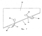
- each of these holes 40 extend to form channels or slots 41 that are inclined relative to the upper surface 33 of the die 30. These inclined channels 41 allow barrier material to flow in to form the barrier walls 9c of the co-extruded assembly 10 as the barrier material passes through the die 30 over the surface 33.
- a frontal view of the die 30 is shown wherein the lower surface 50 of the die 30 is illustrated showing that forms the die profile where the sealant material will pass to form the sealant strips 11 as they pass through a plurality of spaces 51 and lateral extremes 52, 53.
- These lateral extremes 52, 53 are profile depressions that allow the axially outermost sealant strips 20, 22 to be formed wherein the intermediate zones 21 between the barrier wall 9c forming channels 41 are illustrated by the profile space 51 which form the intermediate sealant strips 21 in the finished assembly 10.
- the channels or slits 41 producing the barrier walls 9c be protected so they do not occlude with sealant material.
- the die 30 is constructed with channel flow dividers 56 that project outwardly upstream of the slits 41 in such a fashion that the sealant material will be smoothly diverted around these carved projection surfaces of the flow diverters 56 as the sealant material flows past surrounding the downstream slit 41 directly below the flow divider 56 as the barrier walls 9c as they are being formed such that the sealant strips 11 simultaneously will fill the void spaces 51, 52 and 53 between the barrier layer 9 and the inclined walls 9c forming the plurality of sealant strips 11.
- These projections or flow dividers 56 are profiled as shown in an enlarged view in Figure 7 of the die 30.
- the barrier material will flow down into the holes 40 filling the channel or slit 41 and the sealant material coming from the lower side will be diverted around the flow divider 56 projections in such a fashion that the sealant 11 will flow back onto the inclined walls 9c as they are formed insuring that the entire assembly 10 is produced in a dual extrusion creating both the barrier layer 9 with inclined walls 9c and sealant strips 11 as a simple co-extruded compartmentalized strip and barrier assembly 10 according to the present invention.
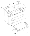
- the die 30 is shown encased in phantom lines representing the extrusion head holding the die 30.
- the extrusion head 60 has two feed nozzles 61, 62.
- One feed nozzle 61 for feeding the barrier material to form the barrier layer 9 within inclined barrier walls 9c as a top surface of the assembly 10 and the second extrusion nozzle 62 providing the sealant material which is shown feeding under the die 30 to form the sealant strips 11.
- the output end of the die head has an opening 63 through which a portion of the assembled co-extruded compartmentalized sealant and barrier assembly 10 is shown coming from the opening 63.
- This Figure is exemplary of how the compartmentalized sealant strip and barrier assembly 10 is formed as a co-extrusion. Alternatively, it may be such that the die 30 is flipped to form the barrier as a lower surface during extrusion and then have the assembly 10 flipped at the tire building station to insure the barrier layer with inclined walls is the top or upper layer of the assembly 10.
Landscapes
- Engineering & Computer Science (AREA)
- Mechanical Engineering (AREA)
- Manufacturing & Machinery (AREA)
- Tires In General (AREA)
Claims (15)
- Verfahren zur Herstellung einer unterteilten Dichtungsstreifen- und Barriere-Anordnung (10), wobei das Verfahren die Schritte umfasst des:Coextrudierens eines Barrierestreifens (9) aus einem nichtdichtenden Elastomermaterial mit einer Vielzahl vorstehender, sich erstreckender Wände (9c) und mindestens eines Dichtungsstreifens (11), wobei der mindestens eine Dichtungsstreifen (11) nur auf einer Seite des Barrierestreifens (9) gebildet ist, wobei er einen Raum zwischen der Vielzahl vorstehender, sich erstreckender Wände (9C) füllt, wodurch er eine Vielzahl sich erstreckender Dichtungsmittelreihen (11) über die Querbreite des Barrierestreifens (9) bildet, derart, dass jede der Dichtungsmittelreihen (11) zwei von den vorstehenden, sich erstreckenden Wänden (9C) begrenzte laterale Seiten, eine von der einen Seite des Barrierestreifens begrenzte Oberseite und eine unbedeckte Unterseite aufweist.
- Verfahren nach Anspruch 1, wobei die vorstehenden, sich erstreckenden Wände (9c) vorstehende, sich linear erstreckende Wände sind und wobei die Vielzahl sich erstreckender Dichtungsmittelreihen (11) eine Vielzahl von sich linear erstreckenden Dichtungsmittelreihen ist.
- Verfahren nach Anspruch 1 oder 2, wobei der Schritt des Coextrudierens weiter den Schritt des Formens der vorstehenden, sich erstreckenden Wände (9c) in einem geneigten Winkel bezüglich einer Ebene senkrecht zur Breite des Barrierestreifens (9) umfasst.
- Verfahren nach mindestens einem der vorgenannten Ansprüche, wobei die coextrudierte Dichtungsstreifen- und Barriere-Anordnung (10) eine Mittelebene (CP) senkrecht zur Breite des Barrierestreifens (9) aufweist und die vorstehenden, sich erstreckenden Wände (9c) ab dem Barrierestreifen (9) geneigt sind, wobei sie sich seitlich auswärts von der Mittelebene (CP) weg erstrecken, um eine Dichtungsmittel-Barrierewand zu bilden, um das Migrieren von Dichtungsmittel zur Mittelebene (CP) der Dichtungsstreifen- und Barriere-Anordnung (10) zu verhindern.
- Verfahren nach mindestens einem der vorgenannten Ansprüche, wobei der Schritt des Coextrudierens weiter den Schritt des Formens des Barrierestreifens (9) mit Seitenkanten (9A, 9B), die sich über das seitliche äußerste Ende des mindestens einen Dichtungsstreifens (11) oder die seitliche äußerste Dichtungsmittelreihe an jeder Seite der Anordnung (10) hinaus erstrecken, umfasst, wobei die Seitenkanten (9A, 9B) bevorzugt Verbundflächen zum Befestigen der Dichtungsstreifen- und Barriere-Anordnung (10) in einer unvulkanisierten Kautschukschicht beim Zusammenbau zu einem unvulkanisierten Reifen sind.
- Verfahren nach mindestens einem der vorgenannten Ansprüche, wobei der Barrierestreifen (9) so geformt ist, dass er beim Einbau in einen Reifen eine Oberschicht der unterteilten Dichtungsstreifen- und Barriere-Anordnung (10) darstellt.
- Verfahren nach mindestens einem der vorgenannten Ansprüche, wobei die geneigten vorstehenden, sich erstreckenden Wände (9c) coextrudiert werden und sich bis zu einer Tiefe zwischen 50 bis 100 Prozent der Dicke des mindestens einen Dichtungsstreifens (11) oder bis zu einer Tiefe gleich der Dicke des mindestens einen Dichtungsstreifens (11) erstrecken.
- Unterteilte Dichtungsstreifen- und Barrierestreifen-Anordnung (10), umfassend:mindestens einen coextrudierten Barrierestreifen (9) aus nichtdichtendem Elastomermaterial, der eine Vielzahl von nur an einer Seite des Barrierestreifens (9) geformten vorstehenden, sich erstreckenden Barrierewänden (9C) aufweist; undeine Vielzahl coextrudierter, sich erstreckender Dichtungsmittelreihen (11), die einen Raum zwischen der Vielzahl vorstehender, sich erstreckender Wände (9C) füllen;die Kombination des mindestens einen coextrudierten Barrierestreifens (9) und der Vielzahl coextrudierter, sich erstreckender Dichtungsmittelreihen (11), die die unterteilte Dichtungsstreifen- und Barriere-Anordnung (10) bilden;dadurch gekennzeichnet, dass jede der Dichtungsmittelreihen (11) zwei von den vorstehenden, sich erstreckenden Wänden (9C) begrenzte laterale Seiten, eine von der einen Seite des Barrierestreifens (9) begrenzte Oberseite und eine unbedeckte Unterseite aufweist.
- Unterteilte Dichtungsstreifen- und Barrierestreifen-Anordnung (10) nach Anspruch 8, wobei die Vielzahl vorstehender, sich erstreckender Barrierewände (9C) eine Vielzahl vorstehender, sich linear erstreckender Barrierewände (9C) ist und wobei die Vielzahl coextrudierter, sich erstreckender Dichtungsmittelreihen (11) eine Vielzahl coextrudierter, sich linear erstreckender Dichtungsmittelreihen (11) ist.
- Unterteilte Dichtungsstreifen- und Barrierestreifen-Anordnung (10) nach Anspruch 8 oder 9, wobei die vorstehenden, sich erstreckenden Barrierewände (9C) sich ab einer Oberseite des Barrierestreifens (9) bis zu einer Tiefe zwischen 50 bis 100 Prozent, bevorzugt 100 Prozent oder ungefähr 100 Prozent, der Dicke der Dichtungsmittelreihen (11) erstrecken; und/oder wobei die Dicke der Dichtungsmittelreihen in einem Bereich von 0,5 bis 2 cm liegt.
- Unterteilte Dichtungsstreifen- und Barrierestreifen-Anordnung (10) nach Ansprüchen 8, 9 oder 10, wobei das Dichtungsmittel, auf Basis von Gewichtsteilen je 100 Gewichtsteile des teilweise depolymerisierten Butylkautschuks unter Ausschluss von Carbon Black, umfasst:(A) einen teilweise organoperoxid-depolymerisierten Butylkautschuk als Copolymer von Isobutylen und Isopren, wobei der Butylkautschuk, vor solcher Depolymerisation, 0,5 bis 5 Prozent von Isopren abgeleitete Einheiten und entsprechend 95 bis 99,5 Gewichtsprozent von Isobutylen abgeleitete Einheiten umfasst;(B) einen partikelförmigen Verstärkungsfüllstoff, umfassend:(i) 20 bis 50 ThK Silika, bevorzugt synthetisches amorphes Silika oder ausgefälltes; oder(ii) 15 bis 30 ThK Silika, bevorzugt synthetisches amorphes Silika oder ausgefälltes Silika, und 5 bis 20 ThK Ton; oder(iii) 15 bis 30 ThK Silika, bevorzugt synthetisches amorphes Silika oder ausgefälltes Silika, und 5 bis 20 ThK Kalziumkarbonat; oder(iv) 15 bis 30 ThK Silika, bevorzugt synthetisches amorphes Silika oder ausgefälltes Silika, 5 bis 15 ThK Ton und 5 bis 15 ThK Kalziumkarbonat;(C) 0 bis 6 ThK organische Kurzfasern;(D) einen Farbstoff von einer anderen als einer schwarzen Farbe, wobei dieser Farbstoff aus mindestens einem von organischen Pigmenten, anorganischen Pigmenten und Färbemitteln ausgewählt ist; und(F) Null bis 20 ThK Kautschukprozessöl.
- Luftreifen, umfassend ein Paar Wülste, mindestens eine sich zwischen den Wülsten erstreckende Karkassenlage, und eine unter der Karkasse befindliche luftundurchlässige Innenisolierung (6), wobei der Reifen weiter die unterteilte Dichtungsstreifen- und Barrierestreifen-Anordnung (10) gemäß mindestens einem der vorgenannten Ansprüche 8 bis 11 umfasst, wobei die unbedeckten Unterseiten der Dichtungsmittelreihen von der Innenisolierung bedeckt sind.
- Extrusionsdüse zum Formen einer unterteilten Dichtungsstreifen- und Barrierestreifen-Anordnung (10), wobei die Extrusionsdüse umfasst:eine Düse (30) mit einem Oberflächenprofil (33) mit einer Vielzahl von sich einwärts erstreckenden Löchern (40), wobei jedes Loch (40) einen Schlitz (41) aufweist, der in eine Abwärtsrichtung offen ist, wobei die Löcher und Schlitze (40, 41) eine wandbildende Öffnung in einem Unterseitenprofil (50) zur Bildung einer Vielzahl von Dichtungsstreifen (9) vorsehen, und wobei der Raum zwischen den wandbildenden Schlitzen (41) und dem Oberflächenprofil (33) eine Vielzahl von Räumen für in Streifen zu formendes Dichtungsmaterial vorsieht.
- Extrusionsdüse nach Anspruch 13, wobei jeder Schlitz (41) sich stromabwärts von einem Stromteiler-Vorsprung befindet, wobei der Stromteiler-Vorsprung ein Dichtungsmittel vor dem Passieren der Schlitze (41) in Streifen teilt.
- Extrusionsdüse nach Anspruch 13 oder 14, wobei die Schlitze (41) geneigt sind, um angewinkelte Barrierewände zu bilden.
Applications Claiming Priority (1)
| Application Number | Priority Date | Filing Date | Title |
|---|---|---|---|
| US13/230,174 US8617334B2 (en) | 2011-09-12 | 2011-09-12 | Method and apparatus for making a compartmentalized tire sealant strip |
Publications (2)
| Publication Number | Publication Date |
|---|---|
| EP2567802A1 EP2567802A1 (de) | 2013-03-13 |
| EP2567802B1 true EP2567802B1 (de) | 2014-09-03 |
Family
ID=46826324
Family Applications (1)
| Application Number | Title | Priority Date | Filing Date |
|---|---|---|---|
| EP12183686.0A Not-in-force EP2567802B1 (de) | 2011-09-12 | 2012-09-10 | Verfahren zur Herstellung eines unterteilten Dichtungsstreifen mit Sperranordnung, der Dichtungsstreifen, Luftreifen mit dem Dichtungsstreifen und Extrusionsdüse |
Country Status (2)
| Country | Link |
|---|---|
| US (3) | US8617334B2 (de) |
| EP (1) | EP2567802B1 (de) |
Cited By (1)
| Publication number | Priority date | Publication date | Assignee | Title |
|---|---|---|---|---|
| EP3653360B1 (de) * | 2018-11-16 | 2024-08-28 | Continental Reifen Deutschland GmbH | Vorform-vorrichtung und verfahren zur herstellung eines fahrzeugluftreifens mit einem laufstreifenabschnitt mit mindestens zwei gummikomponenten |
Families Citing this family (10)
| Publication number | Priority date | Publication date | Assignee | Title |
|---|---|---|---|---|
| US11794530B2 (en) | 2014-12-16 | 2023-10-24 | Triangle Tyre Co. Ltd. | Tire with intrinsic sealant containing intrinsic cellular innermost layer |
| US11738606B2 (en) | 2014-12-16 | 2023-08-29 | Triangle Tyre Co. Ltd. | Multilayer intrinsic sealants based on ionic butyl |
| JP6718692B2 (ja) * | 2016-02-08 | 2020-07-08 | 株式会社ブリヂストン | タイヤ製造方法 |
| JP6831912B2 (ja) | 2016-11-17 | 2021-02-17 | ブリヂストン アメリカズ タイヤ オペレーションズ、 エルエルシー | 空気バリア層を塗布した空気入りタイヤ |
| EP3541640B1 (de) | 2016-11-17 | 2022-08-24 | Bridgestone Americas Tire Operations, LLC | Luftreifen mit an eine luftsperrschicht angehaftetes dämpfungselement |
| WO2018211430A1 (en) * | 2017-05-16 | 2018-11-22 | Sameer Panda | A process for manufacturing tubeless tyre having integrated envelope(s) and a product thereof |
| JP6481072B1 (ja) * | 2018-07-25 | 2019-03-13 | 中田エンヂニアリング株式会社 | ゴム押出装置 |
| US11485062B2 (en) * | 2018-12-19 | 2022-11-01 | The Goodyear Tire & Rubber Company | Apparatus for forming an encapsulated strip |
| US20200198205A1 (en) * | 2018-12-19 | 2020-06-25 | The Goodyear Tire & Rubber Company | Method for forming an encapsulated strip |
| JP7575655B2 (ja) * | 2020-02-28 | 2024-10-30 | 横浜ゴム株式会社 | 空気入りタイヤの製造方法および装置 |
Family Cites Families (37)
| Publication number | Priority date | Publication date | Assignee | Title |
|---|---|---|---|---|
| US1643848A (en) | 1927-09-27 | Method op manufacturing same | ||
| US1959460A (en) * | 1930-07-11 | 1934-05-22 | Jesse R Crossan | Method of producing punctureproof tire tubes |
| US2244648A (en) | 1940-06-05 | 1941-06-03 | Frank G Carnahan | Method of producing self-sealing tire inner tubes |
| US2345200A (en) * | 1940-08-03 | 1944-03-28 | Us Rubber Co | Method of manufacture of inner tubes |
| US2877819A (en) | 1953-03-03 | 1959-03-17 | Seiberling Rubber Co | Puncture sealing pneumatic tire |
| US3444918A (en) | 1967-04-24 | 1969-05-20 | True Car Value Inc | Self-sealing safety tire |
| US3563294A (en) * | 1968-07-02 | 1971-02-16 | Alex Chien | Puncture-sealing band |
| CA987211A (en) | 1973-05-03 | 1976-04-13 | Roy J. Emerson | Puncture sealing means for pneumatic tires |
| US4171237A (en) | 1975-09-22 | 1979-10-16 | The Firestone Tire & Rubber Company | Sealant laminates |
| US4140167A (en) | 1976-08-20 | 1979-02-20 | The Firestone Tire & Rubber Company | Sealant laminates |
| JPS5345803A (en) * | 1976-10-04 | 1978-04-25 | Sumitomo Rubber Ind Ltd | Tire with puncture preventive layer |
| FR2383032A1 (fr) * | 1977-03-08 | 1978-10-06 | Michelin & Cie | Pneumatique avec revetement interne auto-obturant |
| US4209796A (en) * | 1977-11-21 | 1980-06-24 | Massachusetts Institute Of Technology | Charge-flow transistors having metallization patterns |
| FR2425335A1 (fr) * | 1978-05-10 | 1979-12-07 | Michelin & Cie | Pneumatique comportant une garniture de produit obturateur de perforation |
| FR2431379A1 (fr) * | 1978-07-17 | 1980-02-15 | Michelin & Cie | Pneumatique avec revetement d'etancheite vulcanisant en cas de crevaison |
| US4388261A (en) | 1981-10-01 | 1983-06-14 | The General Tire & Rubber Company | Method for forming a compartmented puncture sealant package by co-extrusion |
| US4895610A (en) | 1983-08-15 | 1990-01-23 | The Goodyear Tire & Rubber Company | Self-sealing pneumatic tire and method of manufacturing the same |
| US4664168A (en) | 1985-01-22 | 1987-05-12 | The Uniroyal Goodrich Tire Company | Self-sealing tire with edge strips for tire sealant |
| JPS62236710A (ja) | 1986-04-07 | 1987-10-16 | バブコツク日立株式会社 | ハニカム構造体成型用ダイス |
| US5429856A (en) * | 1990-03-30 | 1995-07-04 | Minnesota Mining And Manufacturing Company | Composite materials and process |
| US20030205308A1 (en) | 1995-05-17 | 2003-11-06 | Honda Giken Kogyo Kabushiki Kaisha | Tire containing a tube |
| JP2002059722A (ja) * | 2000-08-11 | 2002-02-26 | Bridgestone Corp | 安全空気タイヤ及び空気タイヤ用安全チューブ |
| US6746227B2 (en) | 2001-06-19 | 2004-06-08 | The Goodyear Tire & Rubber Company | Tire tread die |
| JP4297241B2 (ja) | 2001-10-18 | 2009-07-15 | 横浜ゴム株式会社 | 空気入りタイヤ |
| JP3837364B2 (ja) | 2002-05-20 | 2006-10-25 | 横浜ゴム株式会社 | セルフシールタイヤの製造方法 |
| US6837287B2 (en) | 2002-06-13 | 2005-01-04 | The Goodyear Tire & Rubber Company | Self-sealing pneumatic tire and preparation thereof |
| US6915826B2 (en) | 2002-12-06 | 2005-07-12 | The Goodyear Tire & Rubber Company | Puncture sealing pneumatic tire |
| KR100513240B1 (ko) * | 2003-11-04 | 2005-09-07 | 금호타이어 주식회사 | 트레드에 방전로를 갖는 타이어 압출성형장치의 다이세트 |
| US7073550B2 (en) | 2004-03-17 | 2006-07-11 | The Goodyear Tire & Rubber Company | Pneumatic tire having built-in colored sealant layer and preparation thereof |
| JP2006014925A (ja) | 2004-07-01 | 2006-01-19 | Pentax Corp | 内視鏡システム |
| JP2006142925A (ja) | 2004-11-18 | 2006-06-08 | Yokohama Rubber Co Ltd:The | 空気入りタイヤおよびその製造方法 |
| US20060169393A1 (en) | 2005-01-28 | 2006-08-03 | Botts Bina P | Method and apparatus for extruding a puncture sealant and mounting on a tire |
| US7607466B2 (en) * | 2006-10-27 | 2009-10-27 | Daniel Kim | Self-sealing tire |
| US20080142140A1 (en) | 2006-12-15 | 2008-06-19 | Patrick David Marks | Method and apparatus for building a puncture sealant tire |
| US8221573B2 (en) | 2007-12-21 | 2012-07-17 | The Goodyear Tire & Rubber Company | Method and apparatus for building a puncture sealant preassembled component |
| US8062017B2 (en) | 2008-10-13 | 2011-11-22 | The Goodyear Tire & Rubber Co | Splice bar for tire tread extrusion apparatus |
| US9878508B2 (en) * | 2010-11-30 | 2018-01-30 | The Goodyear Tire & Rubber Company | Stiffness enhanced tread element |
-
2011
- 2011-09-12 US US13/230,174 patent/US8617334B2/en not_active Expired - Fee Related
-
2012
- 2012-09-10 EP EP12183686.0A patent/EP2567802B1/de not_active Not-in-force
-
2013
- 2013-11-06 US US14/073,224 patent/US9844982B2/en not_active Expired - Fee Related
-
2017
- 2017-11-09 US US15/808,381 patent/US10737539B2/en active Active
Cited By (1)
| Publication number | Priority date | Publication date | Assignee | Title |
|---|---|---|---|---|
| EP3653360B1 (de) * | 2018-11-16 | 2024-08-28 | Continental Reifen Deutschland GmbH | Vorform-vorrichtung und verfahren zur herstellung eines fahrzeugluftreifens mit einem laufstreifenabschnitt mit mindestens zwei gummikomponenten |
Also Published As
| Publication number | Publication date |
|---|---|
| US20180079264A1 (en) | 2018-03-22 |
| US20130061995A1 (en) | 2013-03-14 |
| US8617334B2 (en) | 2013-12-31 |
| US20140060718A1 (en) | 2014-03-06 |
| US10737539B2 (en) | 2020-08-11 |
| US9844982B2 (en) | 2017-12-19 |
| EP2567802A1 (de) | 2013-03-13 |
Similar Documents
| Publication | Publication Date | Title |
|---|---|---|
| US10737539B2 (en) | Method and apparatus for making a compartmentalized tire sealant strip | |
| EP1688239B1 (de) | Verfahren zur Herstellung eines Reifens mit einem eingebrachten Dichtmittel und damit hergestellter Reifen | |
| EP1932655B1 (de) | Verfahren zur Herstellung eines pannensicheren Reifens und damit hergestellter Reifen | |
| US6915826B2 (en) | Puncture sealing pneumatic tire | |
| EP2366533B1 (de) | Luftreifen mit eingebautem Dichtungsschichtsverbundstoff und Verfahren zur Herstellung einer Schicht mit Polyurethan | |
| US8316903B2 (en) | Pneumatic tire having built-in sealant layer and preparation thereof | |
| US20090084482A1 (en) | Pneumatic tire having built-In sealant layer and preparation thereof | |
| US20140130960A1 (en) | Puncture sealant laminate | |
| EP2457742B1 (de) | Luftreifen mit einer Lauffläche mit verbesserter Steifheit und Verfahren zu seiner Herstellung | |
| KR20110046448A (ko) | 공기주입식 물품을 위한 기밀성 및 천공 저항성 적층체 | |
| US12304253B2 (en) | Pneumatic tire | |
| CN107000341A (zh) | 带有多个内置密封胶层的充气轮胎及其制造方法 | |
| US4359354A (en) | Method of forming self-sealing tire body composite for tires | |
| US20090078352A1 (en) | Pneumatic Tire Having Built-In Sealant Layer And Preparation Thereof | |
| US20170001399A1 (en) | Method for forming a tread | |
| US8221573B2 (en) | Method and apparatus for building a puncture sealant preassembled component | |
| US2244648A (en) | Method of producing self-sealing tire inner tubes | |
| JP3837364B2 (ja) | セルフシールタイヤの製造方法 | |
| JP3837351B2 (ja) | セルフシールタイヤの製造方法 | |
| EP2202093A1 (de) | Reifen mit Dichtungsschicht | |
| US20240174026A1 (en) | Two-piece tires with replaceable tread belts and related methods | |
| US20220063222A1 (en) | Tire with composite sealant layer and method of making |
Legal Events
| Date | Code | Title | Description |
|---|---|---|---|
| PUAI | Public reference made under article 153(3) epc to a published international application that has entered the european phase |
Free format text: ORIGINAL CODE: 0009012 |
|
| AK | Designated contracting states |
Kind code of ref document: A1 Designated state(s): AL AT BE BG CH CY CZ DE DK EE ES FI FR GB GR HR HU IE IS IT LI LT LU LV MC MK MT NL NO PL PT RO RS SE SI SK SM TR |
|
| AX | Request for extension of the european patent |
Extension state: BA ME |
|
| 17P | Request for examination filed |
Effective date: 20130913 |
|
| RBV | Designated contracting states (corrected) |
Designated state(s): AL AT BE BG CH CY CZ DE DK EE ES FI FR GB GR HR HU IE IS IT LI LT LU LV MC MK MT NL NO PL PT RO RS SE SI SK SM TR |
|
| GRAP | Despatch of communication of intention to grant a patent |
Free format text: ORIGINAL CODE: EPIDOSNIGR1 |
|
| INTG | Intention to grant announced |
Effective date: 20140411 |
|
| RIC1 | Information provided on ipc code assigned before grant |
Ipc: B29C 47/06 20060101ALI20140331BHEP Ipc: B29C 47/00 20060101ALN20140331BHEP Ipc: B29C 47/14 20060101ALI20140331BHEP Ipc: B29C 47/12 20060101AFI20140331BHEP Ipc: B29D 30/06 20060101ALN20140331BHEP |
|
| GRAS | Grant fee paid |
Free format text: ORIGINAL CODE: EPIDOSNIGR3 |
|
| GRAA | (expected) grant |
Free format text: ORIGINAL CODE: 0009210 |
|
| AK | Designated contracting states |
Kind code of ref document: B1 Designated state(s): AL AT BE BG CH CY CZ DE DK EE ES FI FR GB GR HR HU IE IS IT LI LT LU LV MC MK MT NL NO PL PT RO RS SE SI SK SM TR |
|
| REG | Reference to a national code |
Ref country code: GB Ref legal event code: FG4D |
|
| REG | Reference to a national code |
Ref country code: CH Ref legal event code: EP Ref country code: AT Ref legal event code: REF Ref document number: 685313 Country of ref document: AT Kind code of ref document: T Effective date: 20140915 |
|
| REG | Reference to a national code |
Ref country code: IE Ref legal event code: FG4D |
|
| REG | Reference to a national code |
Ref country code: DE Ref legal event code: R096 Ref document number: 602012002953 Country of ref document: DE Effective date: 20141016 |
|
| REG | Reference to a national code |
Ref country code: AT Ref legal event code: MK05 Ref document number: 685313 Country of ref document: AT Kind code of ref document: T Effective date: 20140903 |
|
| PG25 | Lapsed in a contracting state [announced via postgrant information from national office to epo] |
Ref country code: GR Free format text: LAPSE BECAUSE OF FAILURE TO SUBMIT A TRANSLATION OF THE DESCRIPTION OR TO PAY THE FEE WITHIN THE PRESCRIBED TIME-LIMIT Effective date: 20141204 Ref country code: SE Free format text: LAPSE BECAUSE OF FAILURE TO SUBMIT A TRANSLATION OF THE DESCRIPTION OR TO PAY THE FEE WITHIN THE PRESCRIBED TIME-LIMIT Effective date: 20140903 Ref country code: NO Free format text: LAPSE BECAUSE OF FAILURE TO SUBMIT A TRANSLATION OF THE DESCRIPTION OR TO PAY THE FEE WITHIN THE PRESCRIBED TIME-LIMIT Effective date: 20141203 Ref country code: ES Free format text: LAPSE BECAUSE OF FAILURE TO SUBMIT A TRANSLATION OF THE DESCRIPTION OR TO PAY THE FEE WITHIN THE PRESCRIBED TIME-LIMIT Effective date: 20140903 Ref country code: FI Free format text: LAPSE BECAUSE OF FAILURE TO SUBMIT A TRANSLATION OF THE DESCRIPTION OR TO PAY THE FEE WITHIN THE PRESCRIBED TIME-LIMIT Effective date: 20140903 Ref country code: LT Free format text: LAPSE BECAUSE OF FAILURE TO SUBMIT A TRANSLATION OF THE DESCRIPTION OR TO PAY THE FEE WITHIN THE PRESCRIBED TIME-LIMIT Effective date: 20140903 |
|
| REG | Reference to a national code |
Ref country code: NL Ref legal event code: VDEP Effective date: 20140903 |
|
| REG | Reference to a national code |
Ref country code: LT Ref legal event code: MG4D |
|
| PG25 | Lapsed in a contracting state [announced via postgrant information from national office to epo] |
Ref country code: CY Free format text: LAPSE BECAUSE OF FAILURE TO SUBMIT A TRANSLATION OF THE DESCRIPTION OR TO PAY THE FEE WITHIN THE PRESCRIBED TIME-LIMIT Effective date: 20140903 Ref country code: RS Free format text: LAPSE BECAUSE OF FAILURE TO SUBMIT A TRANSLATION OF THE DESCRIPTION OR TO PAY THE FEE WITHIN THE PRESCRIBED TIME-LIMIT Effective date: 20140903 Ref country code: HR Free format text: LAPSE BECAUSE OF FAILURE TO SUBMIT A TRANSLATION OF THE DESCRIPTION OR TO PAY THE FEE WITHIN THE PRESCRIBED TIME-LIMIT Effective date: 20140903 Ref country code: LV Free format text: LAPSE BECAUSE OF FAILURE TO SUBMIT A TRANSLATION OF THE DESCRIPTION OR TO PAY THE FEE WITHIN THE PRESCRIBED TIME-LIMIT Effective date: 20140903 Ref country code: AT Free format text: LAPSE BECAUSE OF FAILURE TO SUBMIT A TRANSLATION OF THE DESCRIPTION OR TO PAY THE FEE WITHIN THE PRESCRIBED TIME-LIMIT Effective date: 20140903 |
|
| PG25 | Lapsed in a contracting state [announced via postgrant information from national office to epo] |
Ref country code: NL Free format text: LAPSE BECAUSE OF FAILURE TO SUBMIT A TRANSLATION OF THE DESCRIPTION OR TO PAY THE FEE WITHIN THE PRESCRIBED TIME-LIMIT Effective date: 20140903 |
|
| PG25 | Lapsed in a contracting state [announced via postgrant information from national office to epo] |
Ref country code: PT Free format text: LAPSE BECAUSE OF FAILURE TO SUBMIT A TRANSLATION OF THE DESCRIPTION OR TO PAY THE FEE WITHIN THE PRESCRIBED TIME-LIMIT Effective date: 20150105 Ref country code: RO Free format text: LAPSE BECAUSE OF FAILURE TO SUBMIT A TRANSLATION OF THE DESCRIPTION OR TO PAY THE FEE WITHIN THE PRESCRIBED TIME-LIMIT Effective date: 20140903 Ref country code: IS Free format text: LAPSE BECAUSE OF FAILURE TO SUBMIT A TRANSLATION OF THE DESCRIPTION OR TO PAY THE FEE WITHIN THE PRESCRIBED TIME-LIMIT Effective date: 20150103 Ref country code: EE Free format text: LAPSE BECAUSE OF FAILURE TO SUBMIT A TRANSLATION OF THE DESCRIPTION OR TO PAY THE FEE WITHIN THE PRESCRIBED TIME-LIMIT Effective date: 20140903 Ref country code: SK Free format text: LAPSE BECAUSE OF FAILURE TO SUBMIT A TRANSLATION OF THE DESCRIPTION OR TO PAY THE FEE WITHIN THE PRESCRIBED TIME-LIMIT Effective date: 20140903 Ref country code: CZ Free format text: LAPSE BECAUSE OF FAILURE TO SUBMIT A TRANSLATION OF THE DESCRIPTION OR TO PAY THE FEE WITHIN THE PRESCRIBED TIME-LIMIT Effective date: 20140903 |
|
| PG25 | Lapsed in a contracting state [announced via postgrant information from national office to epo] |
Ref country code: PL Free format text: LAPSE BECAUSE OF FAILURE TO SUBMIT A TRANSLATION OF THE DESCRIPTION OR TO PAY THE FEE WITHIN THE PRESCRIBED TIME-LIMIT Effective date: 20140903 |
|
| REG | Reference to a national code |
Ref country code: DE Ref legal event code: R097 Ref document number: 602012002953 Country of ref document: DE |
|
| REG | Reference to a national code |
Ref country code: IE Ref legal event code: MM4A |
|
| REG | Reference to a national code |
Ref country code: FR Ref legal event code: PLFP Year of fee payment: 4 |
|
| PG25 | Lapsed in a contracting state [announced via postgrant information from national office to epo] |
Ref country code: MC Free format text: LAPSE BECAUSE OF FAILURE TO SUBMIT A TRANSLATION OF THE DESCRIPTION OR TO PAY THE FEE WITHIN THE PRESCRIBED TIME-LIMIT Effective date: 20140903 Ref country code: BE Free format text: LAPSE BECAUSE OF NON-PAYMENT OF DUE FEES Effective date: 20140930 |
|
| PLBE | No opposition filed within time limit |
Free format text: ORIGINAL CODE: 0009261 |
|
| STAA | Information on the status of an ep patent application or granted ep patent |
Free format text: STATUS: NO OPPOSITION FILED WITHIN TIME LIMIT |
|
| PG25 | Lapsed in a contracting state [announced via postgrant information from national office to epo] |
Ref country code: DK Free format text: LAPSE BECAUSE OF FAILURE TO SUBMIT A TRANSLATION OF THE DESCRIPTION OR TO PAY THE FEE WITHIN THE PRESCRIBED TIME-LIMIT Effective date: 20140903 |
|
| 26N | No opposition filed |
Effective date: 20150604 |
|
| PG25 | Lapsed in a contracting state [announced via postgrant information from national office to epo] |
Ref country code: IE Free format text: LAPSE BECAUSE OF NON-PAYMENT OF DUE FEES Effective date: 20140910 |
|
| PG25 | Lapsed in a contracting state [announced via postgrant information from national office to epo] |
Ref country code: SI Free format text: LAPSE BECAUSE OF FAILURE TO SUBMIT A TRANSLATION OF THE DESCRIPTION OR TO PAY THE FEE WITHIN THE PRESCRIBED TIME-LIMIT Effective date: 20140903 |
|
| REG | Reference to a national code |
Ref country code: CH Ref legal event code: PL |
|
| PG25 | Lapsed in a contracting state [announced via postgrant information from national office to epo] |
Ref country code: SM Free format text: LAPSE BECAUSE OF FAILURE TO SUBMIT A TRANSLATION OF THE DESCRIPTION OR TO PAY THE FEE WITHIN THE PRESCRIBED TIME-LIMIT Effective date: 20140903 |
|
| PG25 | Lapsed in a contracting state [announced via postgrant information from national office to epo] |
Ref country code: BG Free format text: LAPSE BECAUSE OF FAILURE TO SUBMIT A TRANSLATION OF THE DESCRIPTION OR TO PAY THE FEE WITHIN THE PRESCRIBED TIME-LIMIT Effective date: 20140903 Ref country code: MT Free format text: LAPSE BECAUSE OF FAILURE TO SUBMIT A TRANSLATION OF THE DESCRIPTION OR TO PAY THE FEE WITHIN THE PRESCRIBED TIME-LIMIT Effective date: 20140903 |
|
| PG25 | Lapsed in a contracting state [announced via postgrant information from national office to epo] |
Ref country code: HU Free format text: LAPSE BECAUSE OF FAILURE TO SUBMIT A TRANSLATION OF THE DESCRIPTION OR TO PAY THE FEE WITHIN THE PRESCRIBED TIME-LIMIT; INVALID AB INITIO Effective date: 20120910 Ref country code: LU Free format text: LAPSE BECAUSE OF NON-PAYMENT OF DUE FEES Effective date: 20140910 Ref country code: TR Free format text: LAPSE BECAUSE OF FAILURE TO SUBMIT A TRANSLATION OF THE DESCRIPTION OR TO PAY THE FEE WITHIN THE PRESCRIBED TIME-LIMIT Effective date: 20140903 Ref country code: LI Free format text: LAPSE BECAUSE OF NON-PAYMENT OF DUE FEES Effective date: 20150930 Ref country code: BE Free format text: LAPSE BECAUSE OF FAILURE TO SUBMIT A TRANSLATION OF THE DESCRIPTION OR TO PAY THE FEE WITHIN THE PRESCRIBED TIME-LIMIT Effective date: 20140903 Ref country code: CH Free format text: LAPSE BECAUSE OF NON-PAYMENT OF DUE FEES Effective date: 20150930 |
|
| REG | Reference to a national code |
Ref country code: FR Ref legal event code: PLFP Year of fee payment: 5 |
|
| GBPC | Gb: european patent ceased through non-payment of renewal fee |
Effective date: 20160910 |
|
| PG25 | Lapsed in a contracting state [announced via postgrant information from national office to epo] |
Ref country code: GB Free format text: LAPSE BECAUSE OF NON-PAYMENT OF DUE FEES Effective date: 20160910 |
|
| REG | Reference to a national code |
Ref country code: FR Ref legal event code: PLFP Year of fee payment: 6 |
|
| PG25 | Lapsed in a contracting state [announced via postgrant information from national office to epo] |
Ref country code: MK Free format text: LAPSE BECAUSE OF FAILURE TO SUBMIT A TRANSLATION OF THE DESCRIPTION OR TO PAY THE FEE WITHIN THE PRESCRIBED TIME-LIMIT Effective date: 20140903 |
|
| REG | Reference to a national code |
Ref country code: FR Ref legal event code: PLFP Year of fee payment: 7 |
|
| PG25 | Lapsed in a contracting state [announced via postgrant information from national office to epo] |
Ref country code: AL Free format text: LAPSE BECAUSE OF FAILURE TO SUBMIT A TRANSLATION OF THE DESCRIPTION OR TO PAY THE FEE WITHIN THE PRESCRIBED TIME-LIMIT Effective date: 20140903 |
|
| REG | Reference to a national code |
Ref country code: DE Ref legal event code: R079 Ref document number: 602012002953 Country of ref document: DE Free format text: PREVIOUS MAIN CLASS: B29C0047120000 Ipc: B29C0048300000 |
|
| PGFP | Annual fee paid to national office [announced via postgrant information from national office to epo] |
Ref country code: IT Payment date: 20220811 Year of fee payment: 11 Ref country code: DE Payment date: 20220609 Year of fee payment: 11 |
|
| PGFP | Annual fee paid to national office [announced via postgrant information from national office to epo] |
Ref country code: FR Payment date: 20220709 Year of fee payment: 11 |
|
| REG | Reference to a national code |
Ref country code: DE Ref legal event code: R119 Ref document number: 602012002953 Country of ref document: DE |
|
| PG25 | Lapsed in a contracting state [announced via postgrant information from national office to epo] |
Ref country code: FR Free format text: LAPSE BECAUSE OF NON-PAYMENT OF DUE FEES Effective date: 20230930 Ref country code: DE Free format text: LAPSE BECAUSE OF NON-PAYMENT OF DUE FEES Effective date: 20240403 |
|
| PG25 | Lapsed in a contracting state [announced via postgrant information from national office to epo] |
Ref country code: IT Free format text: LAPSE BECAUSE OF NON-PAYMENT OF DUE FEES Effective date: 20230910 |
|
| PG25 | Lapsed in a contracting state [announced via postgrant information from national office to epo] |
Ref country code: IT Free format text: LAPSE BECAUSE OF NON-PAYMENT OF DUE FEES Effective date: 20230910 |