EP2566163B1 - Image processing apparatus and method - Google Patents
Image processing apparatus and method Download PDFInfo
- Publication number
- EP2566163B1 EP2566163B1 EP12182463.5A EP12182463A EP2566163B1 EP 2566163 B1 EP2566163 B1 EP 2566163B1 EP 12182463 A EP12182463 A EP 12182463A EP 2566163 B1 EP2566163 B1 EP 2566163B1
- Authority
- EP
- European Patent Office
- Prior art keywords
- image
- image data
- processing
- colors
- color
- Prior art date
- Legal status (The legal status is an assumption and is not a legal conclusion. Google has not performed a legal analysis and makes no representation as to the accuracy of the status listed.)
- Active
Links
Images


Classifications
-
- H—ELECTRICITY
- H04—ELECTRIC COMMUNICATION TECHNIQUE
- H04N—PICTORIAL COMMUNICATION, e.g. TELEVISION
- H04N23/00—Cameras or camera modules comprising electronic image sensors; Control thereof
- H04N23/80—Camera processing pipelines; Components thereof
- H04N23/84—Camera processing pipelines; Components thereof for processing colour signals
- H04N23/843—Demosaicing, e.g. interpolating colour pixel values
-
- H—ELECTRICITY
- H04—ELECTRIC COMMUNICATION TECHNIQUE
- H04N—PICTORIAL COMMUNICATION, e.g. TELEVISION
- H04N25/00—Circuitry of solid-state image sensors [SSIS]; Control thereof
- H04N25/10—Circuitry of solid-state image sensors [SSIS]; Control thereof for transforming different wavelengths into image signals
- H04N25/11—Arrangement of colour filter arrays [CFA]; Filter mosaics
- H04N25/13—Arrangement of colour filter arrays [CFA]; Filter mosaics characterised by the spectral characteristics of the filter elements
- H04N25/134—Arrangement of colour filter arrays [CFA]; Filter mosaics characterised by the spectral characteristics of the filter elements based on three different wavelength filter elements
-
- H—ELECTRICITY
- H04—ELECTRIC COMMUNICATION TECHNIQUE
- H04N—PICTORIAL COMMUNICATION, e.g. TELEVISION
- H04N25/00—Circuitry of solid-state image sensors [SSIS]; Control thereof
- H04N25/60—Noise processing, e.g. detecting, correcting, reducing or removing noise
- H04N25/61—Noise processing, e.g. detecting, correcting, reducing or removing noise the noise originating only from the lens unit, e.g. flare, shading, vignetting or "cos4"
- H04N25/611—Correction of chromatic aberration
-
- H—ELECTRICITY
- H04—ELECTRIC COMMUNICATION TECHNIQUE
- H04N—PICTORIAL COMMUNICATION, e.g. TELEVISION
- H04N25/00—Circuitry of solid-state image sensors [SSIS]; Control thereof
- H04N25/60—Noise processing, e.g. detecting, correcting, reducing or removing noise
- H04N25/61—Noise processing, e.g. detecting, correcting, reducing or removing noise the noise originating only from the lens unit, e.g. flare, shading, vignetting or "cos4"
- H04N25/615—Noise processing, e.g. detecting, correcting, reducing or removing noise the noise originating only from the lens unit, e.g. flare, shading, vignetting or "cos4" involving a transfer function modelling the optical system, e.g. optical transfer function [OTF], phase transfer function [PhTF] or modulation transfer function [MTF]
- H04N25/6153—Noise processing, e.g. detecting, correcting, reducing or removing noise the noise originating only from the lens unit, e.g. flare, shading, vignetting or "cos4" involving a transfer function modelling the optical system, e.g. optical transfer function [OTF], phase transfer function [PhTF] or modulation transfer function [MTF] for colour signals
-
- H—ELECTRICITY
- H04—ELECTRIC COMMUNICATION TECHNIQUE
- H04N—PICTORIAL COMMUNICATION, e.g. TELEVISION
- H04N2209/00—Details of colour television systems
- H04N2209/04—Picture signal generators
- H04N2209/041—Picture signal generators using solid-state devices
- H04N2209/042—Picture signal generators using solid-state devices having a single pick-up sensor
- H04N2209/045—Picture signal generators using solid-state devices having a single pick-up sensor using mosaic colour filter
- H04N2209/046—Colour interpolation to calculate the missing colour values
Definitions
- the present invention relates to an image processing apparatus and method and, more particularly, to an image processing apparatus and method which corrects a degraded image by using image recovery processing.
- the causes of blur components in an image include the spherical aberration, comatic aberration, field of curvature, and astigmatism of an optical system.
- Each of the blur components of an image due to these aberrations indicates that a light beam emerging from one point of an object is formed into an image with a spread, which should converge into one point on an imaging plane without any aberration or any influence of diffraction.
- This state is called a PSF (Point Spread Function) in optical terms but will be referred to herein as a blur component in image terms.
- Blur in an image may indicate a defocused image, but is used to indicate herein an image blurred due to the influences of the above aberrations of the optical system, even if it is in focus.
- color fringing on color images due to the chromatic aberration on the axis, spherical aberration of color, and comatic aberration of color of optical systems can be regarded as different ways of blurring at different wavelengths.
- the OTF Optical Transfer Function obtained by Fourier transform of a PSF is frequency component information of an aberration, which is expressed by a complex number.
- the absolute value of an OTF, that is, an amplitude component will be referred to as an MTF (Modulation Transfer Function), and a phase component will be referred to as a PTF (Phase Transfer Function). That is, an MTF and PTF are respectively the frequency characteristics of an amplitude component and phase component of an image's degradation due to aberrations.
- the OTF of an optical imaging system causes degradations in the amplitude component and phase component of an image. For this reason, a degraded image asymmetrically blurs at each point of the imaged object like a comatic aberration.
- the chromatic aberration of magnification occurs when image forming positions shift due to the differences in image forming magnification at different wavelengths of light, and an image sensing apparatus acquires the shifts as R, G, and B color components in accordance with the spectral characteristics.
- Image spreading occurs due to image forming position shifts at different wavelengths within each color component, that is phase shifts, as well as image forming position shifts between R, G, and B components.
- the chromatic aberration of magnification is not simple color fringing due to horizontal shifts. However, color fringing will be used herein as a synonym of the chromatic aberration of magnification.
- image recovery processing As a method of correcting degradations in amplitude (MTF) and phase (PTF), a method of correcting them by using the information of the OTF of an optical imaging system is known. This method is called “image recovery” and “image restoration”. The processing of correcting degradation in image by using the information of the OTF of an optical imaging system will be referred to as image recovery processing.
- Equation (3) may be divided by H as represented by equation (4) given below.
- G u , v / H u , v F u , v
- Returning F(u, v) to the real plane by inverse Fourier transform can obtain the original image f(x, y) as a recovered image.
- a method of suppressing the recovery ratio on the high-frequency side of an image in accordance with the intensity ratio between an image signal and a noise signal such as a method using a Wiener filter.
- a method of correcting degradation in the color fringing component of an image for example, the degradation is corrected by correcting the above blur components so that the amount of blur is made uniform for the respective color components of the image.
- Japanese Patent Laid-Open No. 2006-238032 discloses image recovery processing which is performed upon setting a minute spread in the PSF after image recovery.
- Japanese Patent No. 03532368 discloses a technique of eliminating an image blur in an endoscope for observing the interior of the living body by using a PSF corresponding to a fluorescence wavelength to be used with respect a range outside the in-focus range of an image sensing means. Since the fluorescence is weak, an object optical system with a small f-number is required. This leads to a decrease in focal depth. This technique is therefore designed to obtain an in-focus image by performing image recovery processing with respect to a range in which the optical system goes out of focus.
- An image processing apparatus includes a primary restored image generating module configured to generate a primary restored image by performing image restoration processing on an input image having a plurality of color components, a restoration component generating module configured to generate difference information for each of the plurality of color components by calculating a difference between the input image and the primary restored image, and secondary restored image generating module configured to generate a secondary restored image using the difference information.
- the secondary restored image generating module combines a color-combination restoration component based on the difference information for the plurality of color components with one color component of the input image.
- US 2009/0297056 discloses a method and apparatus for restoring an image captured through an extended depth-of-field lens. Preprocessed data relating to image degradation is stored and used during an image restoration process.
- US2001/0008418 describes a digital camera which acquires information about an optical system such as the arrangement of lenses in image capture, an aperture value, and the like to obtain a degradation function indicating a degradation characteristic of an image relative to the optical system. An image obtained is restored by using the degradation function.
- An area to be restored may be a whole or part of the image. Alternatively, the area to be restored may be reset and restored again on the basis of a restored image.
- the degradation function can also be obtained on the basis of subject movements in a plurality of continuously captured images.
- US 2003/0122926 describes an endoscope system consisting of: an endoscope having a solid-state imaging device and an objective optical system that converges an object image on said solid state imaging device; and a signal processing unit that processes an image signal produced by the endoscope so as to produce a video signal.
- the objective optical system includes an optical phase modulation member.
- the optical phase modulation member exhibits a response of 0.2 or more derived from an optical transfer function relative to up to a spatial frequency on the solid-state imaging device determined based on the Nyquist theorem, that is, a Nyquist frequency, over a wider range of distances than a depth of field offered by an objective optical system not having the optical phase modulation member.
- performing image recovery processing for a sensed input image can improve image quality by correcting aberrations.
- Image recovery processing methods include a method of applying image recovery processing to a RAW image having a signal corresponding to one color component, namely one of the R, G, and B color components; and a method of applying image recovery processing to each color plane after performing interpolation so that each pixel has a signal corresponding to all color components, namely R, G, and B color components.
- the method of applying image recovery processing to each color plane is larger than the method of applying image recovery processing to a RAW image in terms of the number of pixels to which image recovery processing is applied and the number of taps of the recovery filter. This leads to a considerable increase in the processing load of image recovery processing.
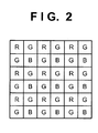
- the color components of the respective pixels constituting a RAW image are often arranged in a Bayer arrangement like that shown in Fig. 2 .
- the number of pixels of a G component is larger than that of R or B components.
- frequency characteristics in the pixel arrangement of a G component in a RAW image differ from those in the pixel arrangement of R and B components.
- the frequency band of a G component differs from that of an R component or B component. In this case, a G component can be recovered in a higher frequency band than that of an R component or B component.
- image recovery processing sometimes generates a false color which has not existed in the original image in an area that includes a high-frequency component in the image. This is because the relationship between the frequency characteristics of R, G, and B components in the high-frequency band of the image has changed before and after the image recovery processing.
- performing image recovery processing for signal components in different frequency bands will generate false colors.
- a false color in this case is generated due to a change in the pixel data itself, which is acquired by an image sensor, unlike a false color generated due to pixel interpolation for an image in a Bayer arrangement. Therefore, using a pixel interpolation algorithm designed to suppress the generation of false colors cannot suppress false colors generated via image recovery processing.
- the present invention has been made in consideration of the above situation, and reduces false colors generated by image recovery processing in a RAW image and reduces the load on image recovery processing.
- the present invention in a first aspect provides an image processing apparatus as specified in claim 1.
- Advantageous embodiments are set out in claims 2 to 3.
- the present invention in another aspect provides an image processing method as specified in claim 4. In yet another aspect there is provided an image processing method as set out in claim 5. A yet further aspect providing a computer program is set out in claim 6.
- Fig. 1 shows an example of the basic arrangement of an image sensing apparatus according to an embodiment of the present invention.
- An object image (not shown) is incident on an image sensor 102 through an optical imaging system 101 which includes a stop 101a and a focus lens 101b.
- the image sensor 102 is covered with, for example, color filters arranged in a so-called Bayer arrangement shown in Fig. 2 .
- Each pixel constituting the image sensor 102 outputs a signal of a color component corresponding to the color of a filter, of the red (R), green (G), and blue (B) color filters, with which the pixel is covered.
- the image sensor 102 converts image forming light into an electrical signal.
- An A/D converter 103 converts the signal into a digital signal and inputs it to an image processing unit 104.
- the image processing unit 104 constitutes an image recovery processing unit 111 and the other image processing unit 112 which performs predetermined processing.
- the image processing unit 112 performs, inter alia, color interpolation processing.
- Each pixel of an output image from the image recovery processing unit 111 includes only a signal of a color component corresponding to one of the filter colors. For this reason, the image processing unit 112 performs color interpolation processing for a recovered image so as to make the respective pixels have signals of color components corresponding to all the filter colors.
- the image processing unit 104 obtains the information of image sensing conditions of the image sensing apparatus from a condition detection unit 107.
- the condition detection unit 107 may directly obtain the information of image sensing conditions from a system controller 110 and can obtain the information of image sensing conditions concerning, for example, an optical imaging system from an optical imaging system control unit 106.
- the image recovery processing unit 111 selects an image recovery filter corresponding to the image sensing conditions from a storage unit 108, and performs image recovery processing for the image input to the image processing unit 104.
- the data held by the storage unit 108 may be information concerning an OTF required to generate an image recovery filter instead of image recovery filters.
- the image recovery processing unit 111 selects information concerning an OTF corresponding to the image sensing conditions from the storage unit 108, and generates an image recovery filter corresponding to the image sensing conditions. The image recovery processing unit 111 then performs image recovery processing for the image input to the image processing unit 104.
- An image recording medium 109 holds the output image processed by the image processing unit 104 in a predetermined format.
- a display unit 105 may display the image obtained by performing predetermined processing for display with respect to the image having undergone the image recovery processing, or may display the image which has not undergone image recovery processing, or which has undergone simple recovery processing.
- the system controller 110 performs a series of control operations.
- the optical imaging system control unit 106 mechanically drives the optical imaging system in accordance with an instruction from the system controller 110.
- the system controller 110 controls the aperture diameter of the stop 101a as an image sensing condition setting for an f-number.
- An AF (autofocus) mechanism or a manual focusing mechanism controls the position of the focus lens 101b so as to perform focus adjustment in accordance with an object distance.
- This optical imaging system 101 may include an optical element such as a low-pass filter or infrared cut filter. When using an element such as a low-pass filter which exerts an influence upon the characteristics of the OTF, it is necessary to consider a change in the OTF due to the optical element at the time of generating an image recovery filter.
- An infrared cut filter also exerts an influence upon the PSFs in RGB channels which are integral values of the PSFs of spectral wavelengths, in particular, upon the PSF in the R channel. Therefore, a change in PSF due to the infrared cut filter is taken into consideration at the time of generating an image recovery filter.
- optical imaging system 101 is configured as part of the image sensing apparatus, but may be exchangeable, as in a single lens reflex camera.
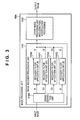
- Fig. 3 shows the arrangement of the image processing unit 104 according to the first embodiment.
- an input image to the image recovery processing unit 111 is RAW data in which each pixel has one of color components, namely R, G, and B color components in a Bayer arrangement like that shown in Fig. 2 .
- a signal separation unit 1101 in the image recovery processing unit 111 separates a G component into G1 and G2 to obtain four image recovery components: R, G1, G2, and B.
- the four image recovery components are then input to recovery filter application units 1110 to 1113 to apply image recovery filters to the components.
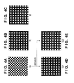
- Figs. 4A to 4E each show an example of each color component in RAW data and each image recovery component.
- Figs. 4A to 4E show three color components in RAW data.
- Fig. 4A shows a G component.
- Fig. 4B shows an R component.
- Fig. 4C shows a B component.
- Each pixel represented by a white square in Figs. 4A to 4E indicates a corresponding color component.
- the G component shown in Fig. 4A is divided into G1 and G2 components shown in Figs. 4D and 4E , and image recovery processing is applied to them.
- a signal of a G component output from a pixel adjacent to a pixel which outputs a signal of an R component in the horizontal direction is a signal of a G1 component
- a signal of a G component output from a pixel adjacent to a pixel which outputs a signal of a B component is a signal of a G2 component.
- Figs. 4A to 4E Fig. 4B shows an image recovery component R
- Fig. 4C shows an image recovery component B
- Fig. 4D shows an image recovery component G1
- Fig. 4E shows an image recovery component G2.
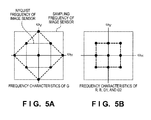
- Figs. 5A and 5B are views showing the spatial frequency characteristics of color-component specific pixel arrangements in the image sensor.
- the respective components shown in Figs. 4A to 4E are respectively represented by m_G(x, y), m_R(x, y), m_B(x, y), m_G1(x, y), and m_G2(x, y), assuming that 1 represents each pixel (represented by a white square) which can sense light and 0 represents each pixel (represented by a black square) which cannot sense light.
- 5A and 5B correspond to the data obtained by Fourier transform of m_G(x, y), m_R(x, y), m_B(x, y), m_G1(x, y), and m_G2(x, y).
- Fig. 5A shows a G component, that is, the spatial frequency characteristics in Fig. 4A , which is a comb function, in which 1s exist only at the positions of " ⁇ ".
- Fig. 5B shows the spatial frequency characteristics of the R and B components shown in Figs. 4B and 4C .
- Fig. 5B differs from Fig. 5A showing the spatial frequency characteristics of the G component.
- the spatial frequency characteristics obtained when the G component is divided into the image recovery components G1 and G2 are the same as those shown in Fig. 5B showing the spatial frequency characteristics of the R and B components.
- the frequency band of the G component to be corrected coincide with that of the R and B components, depending on the way of generating an image recovery filter to be applied to the G component.
- the frequency band to be recovered in this processing is equivalent to that in the processing of separating the G component into the image recovery components G1 and G2.
- the processing of separating the G component into the image recovery components G1 and G2 is more advantageous from the viewpoint of processing loads at the time of convolution of image recovery filters, as will be described later.
- the image recovery processing unit 111 acquires the information of actual image sensing conditions from the condition detection unit 107, as described above.
- the image sensing conditions include, for example, a zooming position, aperture diameter, and object distance.
- the signal separation unit 1101 separates RAW data constituted by R, G, and B components into the four image recovery components R, G1, G2, and B. More specifically, there may be prepared four image data, for R, G1, G2, and B, respectively, each having 0 set at a portion falling under each pixel corresponding to a color component other than target image recovery components. Alternatively, there may be prepared four image data, for R, G1, G2, and B, respectively, each having a 1/4 size, obtained by thinning out a portion given as a pixel corresponding to a color component other than target image recovery components.
- step S13 the image recovery processing unit 111 selects image recovery filters suitable for the acquired image sensing conditions and the four image recovery components R, G1, G2, and B from the storage unit 108. At this time, it is possible to correct the selected image recovery filters as needed. This is the operation of discretely preparing the data of image sensing conditions to reduce the number of image recovery filter data prepared in advance in the storage unit 108 and correcting image recovery filters when actually executing image recovery processing. In addition, if the storage unit 108 holds information concerning OTFs necessary for the generation of image recovery filters instead of image recovery filters, image recovery filters are generated from the selected information concerning OTFs in accordance with image sensing conditions.
- Figs. 7A and 7B are schematic views showing an example of an image recovery filter to be applied to each color plane of an image with each pixel containing the respective color components R, G, and B. It is possible to determine the number of taps of an image recovery filter in accordance with the aberration amount of an optical imaging system. In this case, a two-dimensional filter with 11 x 11 taps is used. Convolution processing is performed for an image in an image recovery process with each tap of the filter corresponding to one pixel of the image. As shown in Fig.
- using a two-dimensional filter obtained by dividing an image recovery filter into 100 or more filters can perform recovery for aberrations widely spreading from image forming positions such as the spherical aberration, comatic aberration, chromatic aberration on the axis, off-axis color flare, and the like of the optical imaging system.
- Fig. 7A omits values in the respective taps.
- Fig. 7B shows one section of this filter.
- This image recovery filter can be generated by the method described above, that is, by calculating or measuring the OTF of an optical element of an optical imaging system and performing inverse Fourier transform of the inverse function.
- Using a Wiener filter can recover a degradation in phase (PTF) and recover a degradation in amplitude (MTF) at different levels for the respective bands.
- an OTF can have a factor that degrades the OTF with respect to not only an optical imaging system but also an image to be input.
- a low-pass filter is used to suppress high-frequency components with respect to the frequency characteristics of the OTF.
- shape and opening ratio of pixel openings of an image sensor also have influences on frequency characteristics.
- such factors include the spectral characteristics of a light source and the spectral characteristics of filters with various wavelengths. It is preferable to generate image recovery filters based on OTFs to encompass the breadth of possible factors that can contribute to degradation of the OTF characteristics.
- an input image is an RGB color image
- it is preferable to generate three image recovery filters corresponding to the respective color components that is, R, G, and B components.
- An optical imaging system has chromatic aberration and varies in the manner of blurring for each color component. For this reason, the characteristics of image recovery filters for the respective color components slightly differ from each other based on chromatic aberrations. That is, the sectional view of Fig. 7A differs for the respective color components.
- the numbers of taps of an image recovery filter in the vertical and horizontal directions need not be determined in accordance with a square arrangement, and can be arbitrarily changed as long as consideration is given to convolution processing.
- This filter is an image recovery filter holding coefficients for pixels in which target color components exist, with each portion holding a coefficient being represented by a white square, and the remaining portions each holding 0 being represented by a black square.
- an image recovery filter to be applied to the R and B components becomes the one shown in Fig. 8A
- an image recovery filter to be applied to the G component becomes the one shown in Fig. 8B .
- the first embodiment applies an image recovery filter upon separating the G component into the image recovery components G1 and G2, and hence can use an image recovery filter like the one shown in Fig. 8A for any of the components R, G1, G2, and B.
- step S14 using the image recovery filter selected in step S13, the recovery filter application units 1110 to 1113 perform convolution processing by filter processing for each pixel of the image recovery components R, G1, G2, and B of an input image which has been sensed. This makes it possible to eliminate or reduce the blur components of the image due to the aberrations caused in the optical imaging system.
- using an image recovery filter suitable for each of the color image recovery components R, G1, G2, and B can also correct chromatic aberration.
- the convolution processing in the first embodiment is convolution processing by filter processing using the image recovery components R, G1, G2, and B shown in Figs. 4B to 4E and the image recovery filter shown in Fig. 8A . It is preferable to change the method of holding image recovery filters or the method of applying filters in accordance with the manner of making each image recovery component separated in step S12 have data, as needed. If, for example, four sets of image data having Os set to portions other than target image recovery components for R, G1, G2, and B, respectively, are used, unnecessary computation can be omitted by limiting target image recovery components to pixels to be subjected to convolution processing.
- this apparatus when preparing four sets of image data, each having a 1/4 size and obtained by thinning out portions other than image recovery components to be processed, for R, G1, G2, and B, respectively, this apparatus also holds the image recovery filter itself while coefficients other than those to be used are thinned out. This makes it possible to directly apply the filter to image data with a 1/4 size.
- the number of effective coefficients of the filter to be used becomes obviously smaller than that of the image recovery filter shown in Fig. 7A which is applied to an image whose pixels all have all color components R, G, and B and that of the image recovery filter shown in Fig. 8B which is applied to the G component which is not separated. This reduces the load of convolution processing.
- the image recovery processing unit 111 finishes the processing. Since the OTF changes in accordance with the angle of view (image height) of the optical imaging system even under one image sensing condition, it is preferable to perform the image recovery processing according to the present invention upon changing the OTF for each segmented area of the image in accordance with the image height. It is preferable to scan an image recovery filter on an image while performing convolution processing and to sequentially change the filter for each area. That is, this apparatus executes steps S13 and S14 for each target pixel of each image recovery component.
- the image data for which the image recovery processing has been performed by the image recovery processing unit 111 is input to the image processing unit 112. Since the image data for which the image recovery processing has been performed remains in a Bayer arrangement, the other image processing unit 112 performs color interpolation processing for each of three color components held by the image sensor.
- the other image processing unit 112 generates an image file in JPEG format or the like by performing known developing processing for RAW data, such as gamma correction and color balance control, in addition to the color interpolation processing.
- a recovery gain is defined as the amplification factor of an MTF in image recovery processing.
- the graph shown in Fig. 9A is an example of the recovery gain of an image recovery filter in the first embodiment. According to the spatial frequency characteristics in the above pixel arrangement of image recovery components, it can be thought that the frequency band to be recovered by an image recovery filter is up to 1/2 the Nyquist frequency of the image sensor.
- the frequency band to be recovered by an image recovery filter is up to the Nyquist frequency of the image sensor according to the spatial frequency characteristics in the pixel arrangement of image recovery components.
- An improvement in MTF in an output image in the JPEG format or the like having undergone image recovery processing according to the first embodiment is not limited to a band up to 1/2 the Nyquist frequency of the image sensor.
- Fig. 9B shows an example of the MTF in an area of an output image according to the first embodiment.
- the MTF has improved even in a band equal to or higher than the Nyquist frequency of the image sensor when image recovery processing is performed as compared with the output image obtained without image recovery processing. This is influenced by the color interpolation processing performed by the other image processing unit 112. Studies have been made on color interpolation processing in an image sensor like that having a Bayer arrangement, and various interpolation techniques have been disclosed.
- the method generally used is adaptive color interpolation processing of generating an interpolated pixel by using the pixel information of other neighboring color components.
- This is a method of determining an interpolation method for the component R of a given pixel by using the information of the components G and B of neighboring pixels when generating the pixel value of the component R of the given pixel by interpolation processing.
- Such adaptive color interpolation processing can suppress the generation of false colors or a degradation in sharpness due to interpolation processing.
- Fig. 10A is a sectional view of a given edge. Assume that the edge is a colorless monochrome portion, and each of color components R, G, and B has a pixel arrangement constituted by pixel values of 100 and 200 as shown in Fig. 10B when the values of the respective color components R, G, and B are acquired by the respective pixels of the image sensor 102.
- the RAW image sensed by the image sensor 102 in a Bayer arrangement has one color component in each pixel, extracting a value for each color component will obtain the pixel arrangements shown in Fig.
- each pixel represented by a black square in the pixel arrangements of the respective color components shown in Figs. 10C to 10E is a pixel requiring color interpolation processing.
- the respective color components after color interpolation processing ideally have the pixel values shown in Fig. 10B .
- the pixel arrangements shown in Figs. 10C to 10E are written as G(x, y), R(x, y), and B(x, y), where x represents a coordinate in the horizontal direction and y represents a coordinate in the vertical direction, each of which has a value in the range of 0 to 4 in Figs. 10A to 10K .
- Equation (6) is computed by using four pixels adjacent to a G component when performing linear interpolation for the G component:
- G x , y G ⁇ x , y - 1 + G ⁇ x - 1 , y + G ⁇ x + 1 , y + G ⁇ x , y + 1 / 4
- Linear interpolation for an R component is performed by using different patterns depending on the position of the pixel to be interpolated.
- This apparatus performs linear interpolation for the B component, in the same manner as for the R component, by applying one of the three patterns represented by equations (7) described above in accordance with the location of the pixel to be interpolated.
- Figs. 10F to 10H show an example of each color component to which the above linear interpolation is applied.
- the interpolation processing has generated pixel values other than 100 and 200. Obviously, therefore, the sharpness of the pixel values is lower than that of the pixel values shown in Fig. 10B .
- the following is an example of the adaptive color interpolation processing of generating interpolated pixels by using the pixel information of other color components around the pixel.
- This adaptive color interpolation processing will be referred to as "adaptive interpolation” hereinafter.
- the apparatus performs adaptive interpolation for the G component in the following manner.
- Determining an interpolation direction based on H_DIFF and V_DIFF calculated from the R component in this manner can suppress a degradation in sharpness due to linear interpolation.
- the apparatus can interpolate the G component of a pixel which has a value in the B component (for example, G(2, 1)) in the same manner.
- the apparatus handles the G component as one color component without separating it into G1 and G2 components, and hence can use the values of more neighboring pixels than when separating the G component into G1 and G2 components. This will improve the MTF in a high frequency band.
- the apparatus performs adaptive interpolation for the R component by using the G signal interpolated by the above method, as indicated by equations (8) given below.
- the apparatus performs adaptive interpolation by interpolating color difference information (R - G) acquired from adjacent pixels in this manner.
- the apparatus performs adaptive interpolation for the B component in the same manner as for the R component, by applying one of the three patterns represented by equations (8) described above depending on the location of the pixel to be interpolated, and interpolating color difference information (B - G) acquired from adjacent pixels.
- Figs. 10I to 10K show an example of each color component to which the above adaptive interpolation is applied.
- the R, G, and B pixel values coincide with each other.
- Each pixel value coincides with that shown in Fig. 10B .
- Performing adaptive interpolation to generate an interpolated pixel using pixel information of other neighboring color components can generate an image without any degradation in sharpness with respect to the pixel arrangement shown in Fig. 10B .
- the apparatus applies image recovery processing for each image recovery component with matching frequency bands and then performs adaptive color interpolation processing for each recovered color component, thereby improving the MTF even in a frequency band higher than the frequency band which the pixel arrangement of each color component has.
- image recovery processing for each image recovery component with matching frequency bands and then performs adaptive color interpolation processing for each recovered color component, thereby improving the MTF even in a frequency band higher than the frequency band which the pixel arrangement of each color component has.
- the arrangement and processing of the image processing unit 104 to which the present invention is applied have been described above.
- the first embodiment has exemplified the general Bayer arrangement constituted by R, G, and B components.
- the present invention can be applied to not only the pixel arrangement constituted by color components R, G, and B but also the pixel arrangement constituted by color components of a plurality of colors other than R, G, and B.
- the present invention can be applied to various types of pixel arrangements in image sensors.
- a general Bayer arrangement constituted by R, G, and B components can be expressed as shown in Fig. 11A when being represented by a pixel arrangement pattern without specifying any colors.
- C1, C2, and C3 each indicate one color component.
- a color component arrangement like that shown in Fig. 11B .
- This is the pixel arrangement of an image sensor constituted by four color components C1, C2, C3, and C4.
- Fig. 12 shows an example of each color component having this pixel arrangement and each image recovery component obtained by application of the present invention.
- the C1 component is separated into four image recovery components.
- the C2 and C3 components are used as image recovery components without any changes.
- the C4 component is separated into two image recovery components. That is, a pixel with a color component higher in spatial frequency characteristics than other color components is separated into a plurality of color components to have the same spatial frequency characteristics as those of other color components. This makes it possible to perform image recovery processing upon unifying the spatial frequency characteristics of the pixel arrangements of the respective image recovery components.
- the present invention can be applied to not only a general Bayer arrangement constituted by R, G, and B components but also various types of pixel arrangements constituted by various types of color components.
- each pixel arrangement is not limited to a matrix arrangement.
- the present invention can be applied to any arrangement that can unify the frequency characteristics of the respective image recovery components by separating a color component of an image sensor.
- Image recovery processing according to the second embodiment of the present invention will be described below. Since the basic arrangement of an image capture apparatus according to the second embodiment is the same as that of the first embodiment shown in Fig. 1 , a description of it will be omitted.
- Fig. 13 shows the arrangement of an image processing unit 104 in the second embodiment.
- the image input to an image recovery processing unit 111 is RAW data with each pixel having a color component of one color of R, G, and B in the Bayer arrangement shown in Fig. 2 .
- the second embodiment applies an image recovery filter to each input RAW data in a Bayer arrangement without any change and without segmenting the RAW data into image recovery components.
- Image recovery filters are respectively applied to four image recovery components in recovery filter application units 1114 to 1117 connected in series.
- step S21 the image recovery processing unit 111 acquires the information of actual image sensing conditions from a condition detection unit 107, as described above.
- the image sensing conditions include, for example, a zooming position, aperture diameter, and object distance.
- an image recovery filter for the R component which is suitable for the acquired image sensing conditions is selected from image recovery filters stored in a storage unit 108 in Fig. 1 .
- the selected image recovery filter may be corrected as needed. This operation is to correct the image recovery filter prepared in the storage unit 108 in advance by preparing discrete image sensing data in advance and correcting the image recovery filter when actually executing image recovery processing in order to reduce the number of data of the image recovery filter.
- step S23 using the image recovery filter of the R component selected in step S22, the recovery filter application unit 1114 performs convolution processing by filter processing with respect to each pixel of the R component of a sensed input image. This can eliminate or reduce the blur component of the R component of the image due to aberrations caused in the optical imaging system. As described above, using an image recovery filter suitable for each image recovery component can also correct chromatic aberration.
- steps S24 to S29 the apparatus performs image recovery processing for image recovery components of G1, G2, and B. Note that the contents of image recovery processing performed in this case are the same as those in steps S22 and S23 except for color components to be corrected, and hence a description of the processing will be omitted.
- the convolution processing for each image recovery component in steps S23, S25, S27, and S29 is convolution processing by filter processing using the respective image recovery components shown in Figs. 4B to 4E and the image recovery filter shown in Fig. 8A .
- Limiting pixels subjected to convolution processing to target image recovery components can omit unnecessary computation.
- the number of effective coefficients of an image recovery filter in this case is smaller than that of an image recovery filter applied to an image each pixel having the respective color components of R, G, and B shown in Fig. 7A and that of an image recovery filter applied to the G component ( Fig. 8B ) which is not separated. This reduces the load of convolution processing.
- RAW data in a Bayer arrangement can be used as an input image without any change, there is no need to ensure the signal separation unit 1101 or any new memory. This can suppress the amount of memory consumed.
- the apparatus performs image recovery processing for each pixel of the image, and terminates the processing in the image recovery processing unit 111. Since the OTF changes in accordance with the angle of view (image height) of the optical imaging system even under one image sensing condition, it is preferable to perform the image recovery processing according to the present invention upon changing the OTF for each segmented area of the image in accordance with the image height. It is preferable to scan an image recovery filter on an image while performing convolution processing and to sequentially change the filter for each area. That is, this apparatus executes steps S22 and S23 for each pixel of the R component, and executes steps S24 to S29 for each image recovery component to be processed in the same manner as described above.
- first and second embodiments have handled the application of image recovery filters as image recovery processing, it is possible to handle other types of processing such as distortion correction processing, peripheral light amount correction processing, and noise reduction processing before, after, and midway through the procedure of the present invention and handle the resultant procedure as image recovery processing.
- aspects of the present invention can also be realized by a computer of a system or apparatus (or devices such as a CPU or MPU) that reads out and executes a program recorded on a memory device to perform the functions of the above-described embodiment(s), and by a method, the steps of which are performed by a computer of a system or apparatus by, for example, reading out and executing a program recorded on a memory device to perform the functions of the above-described embodiment(s).
- the program is provided to the computer for example via a network or from a recording medium of various types serving as the memory device (for example, computer-readable medium).
Landscapes
- Engineering & Computer Science (AREA)
- Multimedia (AREA)
- Signal Processing (AREA)
- Physics & Mathematics (AREA)
- Spectroscopy & Molecular Physics (AREA)
- Color Television Image Signal Generators (AREA)
- Image Processing (AREA)
- Studio Devices (AREA)
Applications Claiming Priority (1)
| Application Number | Priority Date | Filing Date | Title |
|---|---|---|---|
| JP2011187856A JP5824297B2 (ja) | 2011-08-30 | 2011-08-30 | 画像処理装置及び方法、及び撮像装置 |
Publications (3)
| Publication Number | Publication Date |
|---|---|
| EP2566163A2 EP2566163A2 (en) | 2013-03-06 |
| EP2566163A3 EP2566163A3 (en) | 2013-05-15 |
| EP2566163B1 true EP2566163B1 (en) | 2014-07-30 |
Family
ID=46754342
Family Applications (1)
| Application Number | Title | Priority Date | Filing Date |
|---|---|---|---|
| EP12182463.5A Active EP2566163B1 (en) | 2011-08-30 | 2012-08-30 | Image processing apparatus and method |
Country Status (5)
| Country | Link |
|---|---|
| US (1) | US8754957B2 (enExample) |
| EP (1) | EP2566163B1 (enExample) |
| JP (1) | JP5824297B2 (enExample) |
| CN (1) | CN102968761B (enExample) |
| RU (1) | RU2523924C2 (enExample) |
Families Citing this family (43)
| Publication number | Priority date | Publication date | Assignee | Title |
|---|---|---|---|---|
| US10298834B2 (en) | 2006-12-01 | 2019-05-21 | Google Llc | Video refocusing |
| JP5535053B2 (ja) * | 2010-11-26 | 2014-07-02 | キヤノン株式会社 | 画像処理装置、及び画像処理方法 |
| JP5378627B2 (ja) * | 2011-03-11 | 2013-12-25 | 富士フイルム株式会社 | 撮像装置およびその動作制御方法ならびに撮像システム |
| US20130321675A1 (en) * | 2012-05-31 | 2013-12-05 | Apple Inc. | Raw scaler with chromatic aberration correction |
| US9858649B2 (en) | 2015-09-30 | 2018-01-02 | Lytro, Inc. | Depth-based image blurring |
| US10334151B2 (en) | 2013-04-22 | 2019-06-25 | Google Llc | Phase detection autofocus using subaperture images |
| JP5961149B2 (ja) | 2013-08-26 | 2016-08-02 | キヤノン株式会社 | 画像処理装置およびその制御方法 |
| JP6153424B2 (ja) * | 2013-08-29 | 2017-06-28 | キヤノン株式会社 | 焦点検出装置および撮像装置並びに焦点検出方法、プログラム |
| KR102218832B1 (ko) | 2014-12-16 | 2021-02-24 | 삼성전자주식회사 | 컬러 프린지를 제거하기 위한 이미지 처리 장치 |
| KR102255218B1 (ko) * | 2014-12-18 | 2021-05-24 | 삼성전자주식회사 | 컬러 프린지를 제거하기 위한 이미지 처리 장치 |
| JP6185213B2 (ja) * | 2015-03-31 | 2017-08-23 | 富士フイルム株式会社 | 撮像装置及び撮像装置の画像処理方法及びプログラム |
| US10469873B2 (en) | 2015-04-15 | 2019-11-05 | Google Llc | Encoding and decoding virtual reality video |
| US10419737B2 (en) | 2015-04-15 | 2019-09-17 | Google Llc | Data structures and delivery methods for expediting virtual reality playback |
| US10412373B2 (en) | 2015-04-15 | 2019-09-10 | Google Llc | Image capture for virtual reality displays |
| US11328446B2 (en) | 2015-04-15 | 2022-05-10 | Google Llc | Combining light-field data with active depth data for depth map generation |
| US10567464B2 (en) | 2015-04-15 | 2020-02-18 | Google Llc | Video compression with adaptive view-dependent lighting removal |
| US10546424B2 (en) | 2015-04-15 | 2020-01-28 | Google Llc | Layered content delivery for virtual and augmented reality experiences |
| US10540818B2 (en) | 2015-04-15 | 2020-01-21 | Google Llc | Stereo image generation and interactive playback |
| US10440407B2 (en) | 2017-05-09 | 2019-10-08 | Google Llc | Adaptive control for immersive experience delivery |
| US10444931B2 (en) | 2017-05-09 | 2019-10-15 | Google Llc | Vantage generation and interactive playback |
| US10341632B2 (en) | 2015-04-15 | 2019-07-02 | Google Llc. | Spatial random access enabled video system with a three-dimensional viewing volume |
| US10275898B1 (en) | 2015-04-15 | 2019-04-30 | Google Llc | Wedge-based light-field video capture |
| US10565734B2 (en) | 2015-04-15 | 2020-02-18 | Google Llc | Video capture, processing, calibration, computational fiber artifact removal, and light-field pipeline |
| JP6240813B2 (ja) | 2015-04-23 | 2017-11-29 | 富士フイルム株式会社 | 画像処理装置、撮像装置、画像処理方法及び画像処理プログラム |
| CN107534727B (zh) * | 2015-04-23 | 2020-06-26 | 富士胶片株式会社 | 图像处理装置、摄像装置、图像处理方法及记录有图像处理程序的计算机可读非暂时性有形记录介质 |
| JP6603493B2 (ja) | 2015-06-29 | 2019-11-06 | キヤノン株式会社 | 撮像装置、画像処理装置、撮像装置が実行する撮像方法、画像処理装置が実行する画像処理方法、及びプログラム |
| US9979909B2 (en) * | 2015-07-24 | 2018-05-22 | Lytro, Inc. | Automatic lens flare detection and correction for light-field images |
| CN105118026A (zh) * | 2015-07-28 | 2015-12-02 | 小米科技有限责任公司 | 色域模式切换方法及装置 |
| US10275892B2 (en) | 2016-06-09 | 2019-04-30 | Google Llc | Multi-view scene segmentation and propagation |
| JP6765064B2 (ja) * | 2016-06-23 | 2020-10-07 | パナソニックIpマネジメント株式会社 | 赤外線検出装置 |
| US10679361B2 (en) | 2016-12-05 | 2020-06-09 | Google Llc | Multi-view rotoscope contour propagation |
| CN106651811B (zh) * | 2017-01-03 | 2018-03-16 | 长沙全度影像科技有限公司 | 一种亮度通道引导的简单镜头成像模糊去除方法 |
| CN106651812B (zh) * | 2017-01-03 | 2018-06-26 | 长沙全度影像科技有限公司 | 一种简单镜头成像的多通道psf标定方法 |
| US10594945B2 (en) | 2017-04-03 | 2020-03-17 | Google Llc | Generating dolly zoom effect using light field image data |
| US10474227B2 (en) | 2017-05-09 | 2019-11-12 | Google Llc | Generation of virtual reality with 6 degrees of freedom from limited viewer data |
| US10354399B2 (en) | 2017-05-25 | 2019-07-16 | Google Llc | Multi-view back-projection to a light-field |
| JP6960997B2 (ja) * | 2017-08-09 | 2021-11-05 | 富士フイルム株式会社 | 画像処理システム、サーバ装置、画像処理方法、及び画像処理プログラム |
| US10545215B2 (en) | 2017-09-13 | 2020-01-28 | Google Llc | 4D camera tracking and optical stabilization |
| US10965862B2 (en) | 2018-01-18 | 2021-03-30 | Google Llc | Multi-camera navigation interface |
| CN110793564A (zh) * | 2018-08-02 | 2020-02-14 | 昆山博威泰克电子科技有限公司 | 视觉检测设备和视觉检测方法 |
| US10667693B1 (en) * | 2018-11-16 | 2020-06-02 | Perkinelmer Health Sciences, Inc. | Systems, methods, and apparatus for interference filter correction based on angle of incidence |
| JP7337555B2 (ja) * | 2019-06-10 | 2023-09-04 | キヤノン株式会社 | 画像処理装置、撮像装置、画像処理方法、プログラム、および、記憶媒体 |
| JP7408315B2 (ja) * | 2019-08-19 | 2024-01-05 | キヤノン株式会社 | 画像処理装置、画像処理方法、及びプログラム |
Family Cites Families (15)
| Publication number | Priority date | Publication date | Assignee | Title |
|---|---|---|---|---|
| JP3532368B2 (ja) | 1996-12-10 | 2004-05-31 | 富士写真フイルム株式会社 | 内視鏡 |
| US20010008418A1 (en) * | 2000-01-13 | 2001-07-19 | Minolta Co., Ltd. | Image processing apparatus and method |
| JP4043197B2 (ja) * | 2000-03-24 | 2008-02-06 | 三洋電機株式会社 | 単板式カラーカメラの色分離回路 |
| JP3791777B2 (ja) | 2001-12-28 | 2006-06-28 | オリンパス株式会社 | 電子内視鏡 |
| US20040165090A1 (en) * | 2003-02-13 | 2004-08-26 | Alex Ning | Auto-focus (AF) lens and process |
| JP2006238032A (ja) | 2005-02-24 | 2006-09-07 | Matsushita Electric Ind Co Ltd | 画像復元方法およびその装置 |
| RU2298226C1 (ru) * | 2005-10-28 | 2007-04-27 | Самсунг Электроникс Ко., Лтд. | Способ улучшения цифровых изображений |
| JP4501855B2 (ja) * | 2005-12-22 | 2010-07-14 | ソニー株式会社 | 画像信号処理装置、撮像装置、および画像信号処理方法、並びにコンピュータ・プログラム |
| RU2352987C1 (ru) * | 2007-09-03 | 2009-04-20 | Государственное образовательное учреждение высшего профессионального образования Курский государственный технический университет | Устройство получения изображения с коррекцией хроматической аберрации |
| JP2009089082A (ja) * | 2007-09-28 | 2009-04-23 | Kyocera Corp | 画像復元装置およびその方法 |
| US8131097B2 (en) | 2008-05-28 | 2012-03-06 | Aptina Imaging Corporation | Method and apparatus for extended depth-of-field image restoration |
| JP4986965B2 (ja) * | 2008-09-30 | 2012-07-25 | キヤノン株式会社 | 画像処理方法、画像処理装置、画像処理プログラム及び撮像装置 |
| JP5487845B2 (ja) * | 2009-09-24 | 2014-05-14 | ソニー株式会社 | 撮像素子、駆動制御方法、並びにプログラム |
| JP5490139B2 (ja) * | 2009-10-13 | 2014-05-14 | キヤノン株式会社 | 撮像装置 |
| CN102714737B (zh) * | 2009-12-17 | 2015-12-02 | 佳能株式会社 | 图像处理设备和使用图像处理设备的图像捕获装置 |
-
2011
- 2011-08-30 JP JP2011187856A patent/JP5824297B2/ja active Active
-
2012
- 2012-08-15 US US13/585,895 patent/US8754957B2/en active Active
- 2012-08-29 RU RU2012136949/08A patent/RU2523924C2/ru active
- 2012-08-30 CN CN201210317231.6A patent/CN102968761B/zh active Active
- 2012-08-30 EP EP12182463.5A patent/EP2566163B1/en active Active
Also Published As
| Publication number | Publication date |
|---|---|
| RU2523924C2 (ru) | 2014-07-27 |
| JP5824297B2 (ja) | 2015-11-25 |
| US20130050546A1 (en) | 2013-02-28 |
| EP2566163A2 (en) | 2013-03-06 |
| JP2013051524A (ja) | 2013-03-14 |
| EP2566163A3 (en) | 2013-05-15 |
| CN102968761A (zh) | 2013-03-13 |
| RU2012136949A (ru) | 2014-03-10 |
| CN102968761B (zh) | 2015-10-28 |
| US8754957B2 (en) | 2014-06-17 |
Similar Documents
| Publication | Publication Date | Title |
|---|---|---|
| EP2566163B1 (en) | Image processing apparatus and method | |
| EP2574034B1 (en) | Image processing apparatus and method | |
| JP5546229B2 (ja) | 画像処理方法、画像処理装置、撮像装置および画像処理プログラム | |
| US8941762B2 (en) | Image processing apparatus and image pickup apparatus using the same | |
| JP6525718B2 (ja) | 画像処理装置、その制御方法、および制御プログラム | |
| JP6327922B2 (ja) | 画像処理装置、画像処理方法、およびプログラム | |
| JP5188651B2 (ja) | 画像処理装置、およびそれを用いた撮像装置 | |
| JP5441652B2 (ja) | 画像処理方法、画像処理装置、撮像装置および画像処理プログラム | |
| JP2011123589A5 (enExample) | ||
| JP2011124692A5 (enExample) | ||
| JP2014027570A (ja) | 画像処理方法、画像処理プログラム、画像処理装置および撮像装置 | |
| WO2011121763A1 (ja) | 画像処理装置、およびそれを用いた撮像装置 | |
| JP2012156715A (ja) | 画像処理装置、撮像装置、画像処理方法およびプログラム。 | |
| JP7646427B2 (ja) | 画像処理方法、画像処理装置、撮像装置およびプログラム | |
| US20240144536A1 (en) | Image processing device, image processing method, and storage medium | |
| JP6238673B2 (ja) | 画像処理装置、撮像装置、撮像システム、画像処理方法、画像処理プログラム、および、記憶媒体 | |
| JP6552375B2 (ja) | 画像処理装置、撮像装置および画像処理プログラム | |
| JP2017118293A (ja) | 画像処理装置、撮像装置、画像処理方法、画像処理プログラム、および、記憶媒体 | |
| JP2017224906A (ja) | 画像処理方法およびそれを用いた撮像装置、画像処理装置、画像処理プログラム |
Legal Events
| Date | Code | Title | Description |
|---|---|---|---|
| PUAI | Public reference made under article 153(3) epc to a published international application that has entered the european phase |
Free format text: ORIGINAL CODE: 0009012 |
|
| AK | Designated contracting states |
Kind code of ref document: A2 Designated state(s): AL AT BE BG CH CY CZ DE DK EE ES FI FR GB GR HR HU IE IS IT LI LT LU LV MC MK MT NL NO PL PT RO RS SE SI SK SM TR |
|
| AX | Request for extension of the european patent |
Extension state: BA ME |
|
| PUAL | Search report despatched |
Free format text: ORIGINAL CODE: 0009013 |
|
| AK | Designated contracting states |
Kind code of ref document: A3 Designated state(s): AL AT BE BG CH CY CZ DE DK EE ES FI FR GB GR HR HU IE IS IT LI LT LU LV MC MK MT NL NO PL PT RO RS SE SI SK SM TR |
|
| AX | Request for extension of the european patent |
Extension state: BA ME |
|
| RIC1 | Information provided on ipc code assigned before grant |
Ipc: H04N 9/04 20060101AFI20130408BHEP Ipc: H04N 5/357 20110101ALI20130408BHEP |
|
| 17P | Request for examination filed |
Effective date: 20131115 |
|
| RBV | Designated contracting states (corrected) |
Designated state(s): AL AT BE BG CH CY CZ DE DK EE ES FI FR GB GR HR HU IE IS IT LI LT LU LV MC MK MT NL NO PL PT RO RS SE SI SK SM TR |
|
| GRAP | Despatch of communication of intention to grant a patent |
Free format text: ORIGINAL CODE: EPIDOSNIGR1 |
|
| INTG | Intention to grant announced |
Effective date: 20140220 |
|
| RIN1 | Information on inventor provided before grant (corrected) |
Inventor name: KANO, AKIRA |
|
| GRAS | Grant fee paid |
Free format text: ORIGINAL CODE: EPIDOSNIGR3 |
|
| GRAA | (expected) grant |
Free format text: ORIGINAL CODE: 0009210 |
|
| AK | Designated contracting states |
Kind code of ref document: B1 Designated state(s): AL AT BE BG CH CY CZ DE DK EE ES FI FR GB GR HR HU IE IS IT LI LT LU LV MC MK MT NL NO PL PT RO RS SE SI SK SM TR |
|
| REG | Reference to a national code |
Ref country code: GB Ref legal event code: FG4D |
|
| REG | Reference to a national code |
Ref country code: CH Ref legal event code: EP |
|
| REG | Reference to a national code |
Ref country code: AT Ref legal event code: REF Ref document number: 680450 Country of ref document: AT Kind code of ref document: T Effective date: 20140815 |
|
| REG | Reference to a national code |
Ref country code: IE Ref legal event code: FG4D |
|
| REG | Reference to a national code |
Ref country code: DE Ref legal event code: R096 Ref document number: 602012002571 Country of ref document: DE Effective date: 20140911 |
|
| REG | Reference to a national code |
Ref country code: AT Ref legal event code: MK05 Ref document number: 680450 Country of ref document: AT Kind code of ref document: T Effective date: 20140730 |
|
| REG | Reference to a national code |
Ref country code: NL Ref legal event code: VDEP Effective date: 20140730 |
|
| REG | Reference to a national code |
Ref country code: LT Ref legal event code: MG4D |
|
| PG25 | Lapsed in a contracting state [announced via postgrant information from national office to epo] |
Ref country code: ES Free format text: LAPSE BECAUSE OF FAILURE TO SUBMIT A TRANSLATION OF THE DESCRIPTION OR TO PAY THE FEE WITHIN THE PRESCRIBED TIME-LIMIT Effective date: 20140730 Ref country code: NO Free format text: LAPSE BECAUSE OF FAILURE TO SUBMIT A TRANSLATION OF THE DESCRIPTION OR TO PAY THE FEE WITHIN THE PRESCRIBED TIME-LIMIT Effective date: 20141030 Ref country code: BG Free format text: LAPSE BECAUSE OF FAILURE TO SUBMIT A TRANSLATION OF THE DESCRIPTION OR TO PAY THE FEE WITHIN THE PRESCRIBED TIME-LIMIT Effective date: 20141030 Ref country code: LT Free format text: LAPSE BECAUSE OF FAILURE TO SUBMIT A TRANSLATION OF THE DESCRIPTION OR TO PAY THE FEE WITHIN THE PRESCRIBED TIME-LIMIT Effective date: 20140730 Ref country code: SE Free format text: LAPSE BECAUSE OF FAILURE TO SUBMIT A TRANSLATION OF THE DESCRIPTION OR TO PAY THE FEE WITHIN THE PRESCRIBED TIME-LIMIT Effective date: 20140730 Ref country code: FI Free format text: LAPSE BECAUSE OF FAILURE TO SUBMIT A TRANSLATION OF THE DESCRIPTION OR TO PAY THE FEE WITHIN THE PRESCRIBED TIME-LIMIT Effective date: 20140730 Ref country code: GR Free format text: LAPSE BECAUSE OF FAILURE TO SUBMIT A TRANSLATION OF THE DESCRIPTION OR TO PAY THE FEE WITHIN THE PRESCRIBED TIME-LIMIT Effective date: 20141031 Ref country code: PT Free format text: LAPSE BECAUSE OF FAILURE TO SUBMIT A TRANSLATION OF THE DESCRIPTION OR TO PAY THE FEE WITHIN THE PRESCRIBED TIME-LIMIT Effective date: 20141202 |
|
| PG25 | Lapsed in a contracting state [announced via postgrant information from national office to epo] |
Ref country code: AT Free format text: LAPSE BECAUSE OF FAILURE TO SUBMIT A TRANSLATION OF THE DESCRIPTION OR TO PAY THE FEE WITHIN THE PRESCRIBED TIME-LIMIT Effective date: 20140730 Ref country code: NL Free format text: LAPSE BECAUSE OF FAILURE TO SUBMIT A TRANSLATION OF THE DESCRIPTION OR TO PAY THE FEE WITHIN THE PRESCRIBED TIME-LIMIT Effective date: 20140730 Ref country code: LV Free format text: LAPSE BECAUSE OF FAILURE TO SUBMIT A TRANSLATION OF THE DESCRIPTION OR TO PAY THE FEE WITHIN THE PRESCRIBED TIME-LIMIT Effective date: 20140730 Ref country code: RS Free format text: LAPSE BECAUSE OF FAILURE TO SUBMIT A TRANSLATION OF THE DESCRIPTION OR TO PAY THE FEE WITHIN THE PRESCRIBED TIME-LIMIT Effective date: 20140730 Ref country code: IS Free format text: LAPSE BECAUSE OF FAILURE TO SUBMIT A TRANSLATION OF THE DESCRIPTION OR TO PAY THE FEE WITHIN THE PRESCRIBED TIME-LIMIT Effective date: 20141130 Ref country code: PL Free format text: LAPSE BECAUSE OF FAILURE TO SUBMIT A TRANSLATION OF THE DESCRIPTION OR TO PAY THE FEE WITHIN THE PRESCRIBED TIME-LIMIT Effective date: 20140730 Ref country code: CY Free format text: LAPSE BECAUSE OF FAILURE TO SUBMIT A TRANSLATION OF THE DESCRIPTION OR TO PAY THE FEE WITHIN THE PRESCRIBED TIME-LIMIT Effective date: 20140730 Ref country code: HR Free format text: LAPSE BECAUSE OF FAILURE TO SUBMIT A TRANSLATION OF THE DESCRIPTION OR TO PAY THE FEE WITHIN THE PRESCRIBED TIME-LIMIT Effective date: 20140730 |
|
| PG25 | Lapsed in a contracting state [announced via postgrant information from national office to epo] |
Ref country code: SK Free format text: LAPSE BECAUSE OF FAILURE TO SUBMIT A TRANSLATION OF THE DESCRIPTION OR TO PAY THE FEE WITHIN THE PRESCRIBED TIME-LIMIT Effective date: 20140730 Ref country code: DK Free format text: LAPSE BECAUSE OF FAILURE TO SUBMIT A TRANSLATION OF THE DESCRIPTION OR TO PAY THE FEE WITHIN THE PRESCRIBED TIME-LIMIT Effective date: 20140730 Ref country code: RO Free format text: LAPSE BECAUSE OF FAILURE TO SUBMIT A TRANSLATION OF THE DESCRIPTION OR TO PAY THE FEE WITHIN THE PRESCRIBED TIME-LIMIT Effective date: 20140730 Ref country code: IT Free format text: LAPSE BECAUSE OF FAILURE TO SUBMIT A TRANSLATION OF THE DESCRIPTION OR TO PAY THE FEE WITHIN THE PRESCRIBED TIME-LIMIT Effective date: 20140730 Ref country code: BE Free format text: LAPSE BECAUSE OF NON-PAYMENT OF DUE FEES Effective date: 20140831 Ref country code: EE Free format text: LAPSE BECAUSE OF FAILURE TO SUBMIT A TRANSLATION OF THE DESCRIPTION OR TO PAY THE FEE WITHIN THE PRESCRIBED TIME-LIMIT Effective date: 20140730 Ref country code: CZ Free format text: LAPSE BECAUSE OF FAILURE TO SUBMIT A TRANSLATION OF THE DESCRIPTION OR TO PAY THE FEE WITHIN THE PRESCRIBED TIME-LIMIT Effective date: 20140730 Ref country code: MC Free format text: LAPSE BECAUSE OF FAILURE TO SUBMIT A TRANSLATION OF THE DESCRIPTION OR TO PAY THE FEE WITHIN THE PRESCRIBED TIME-LIMIT Effective date: 20140730 |
|
| REG | Reference to a national code |
Ref country code: DE Ref legal event code: R097 Ref document number: 602012002571 Country of ref document: DE |
|
| REG | Reference to a national code |
Ref country code: IE Ref legal event code: MM4A |
|
| PLBE | No opposition filed within time limit |
Free format text: ORIGINAL CODE: 0009261 |
|
| STAA | Information on the status of an ep patent application or granted ep patent |
Free format text: STATUS: NO OPPOSITION FILED WITHIN TIME LIMIT |
|
| 26N | No opposition filed |
Effective date: 20150504 |
|
| REG | Reference to a national code |
Ref country code: FR Ref legal event code: ST Effective date: 20150612 |
|
| PG25 | Lapsed in a contracting state [announced via postgrant information from national office to epo] |
Ref country code: IE Free format text: LAPSE BECAUSE OF NON-PAYMENT OF DUE FEES Effective date: 20140830 Ref country code: FR Free format text: LAPSE BECAUSE OF NON-PAYMENT OF DUE FEES Effective date: 20140930 |
|
| PG25 | Lapsed in a contracting state [announced via postgrant information from national office to epo] |
Ref country code: SI Free format text: LAPSE BECAUSE OF FAILURE TO SUBMIT A TRANSLATION OF THE DESCRIPTION OR TO PAY THE FEE WITHIN THE PRESCRIBED TIME-LIMIT Effective date: 20140730 |
|
| REG | Reference to a national code |
Ref country code: CH Ref legal event code: PL |
|
| PG25 | Lapsed in a contracting state [announced via postgrant information from national office to epo] |
Ref country code: CH Free format text: LAPSE BECAUSE OF NON-PAYMENT OF DUE FEES Effective date: 20150831 Ref country code: LI Free format text: LAPSE BECAUSE OF NON-PAYMENT OF DUE FEES Effective date: 20150831 |
|
| PG25 | Lapsed in a contracting state [announced via postgrant information from national office to epo] |
Ref country code: SM Free format text: LAPSE BECAUSE OF FAILURE TO SUBMIT A TRANSLATION OF THE DESCRIPTION OR TO PAY THE FEE WITHIN THE PRESCRIBED TIME-LIMIT Effective date: 20140730 |
|
| PG25 | Lapsed in a contracting state [announced via postgrant information from national office to epo] |
Ref country code: MT Free format text: LAPSE BECAUSE OF FAILURE TO SUBMIT A TRANSLATION OF THE DESCRIPTION OR TO PAY THE FEE WITHIN THE PRESCRIBED TIME-LIMIT Effective date: 20140730 |
|
| PG25 | Lapsed in a contracting state [announced via postgrant information from national office to epo] |
Ref country code: LU Free format text: LAPSE BECAUSE OF NON-PAYMENT OF DUE FEES Effective date: 20140830 Ref country code: TR Free format text: LAPSE BECAUSE OF FAILURE TO SUBMIT A TRANSLATION OF THE DESCRIPTION OR TO PAY THE FEE WITHIN THE PRESCRIBED TIME-LIMIT Effective date: 20140730 Ref country code: HU Free format text: LAPSE BECAUSE OF FAILURE TO SUBMIT A TRANSLATION OF THE DESCRIPTION OR TO PAY THE FEE WITHIN THE PRESCRIBED TIME-LIMIT; INVALID AB INITIO Effective date: 20120830 Ref country code: BE Free format text: LAPSE BECAUSE OF FAILURE TO SUBMIT A TRANSLATION OF THE DESCRIPTION OR TO PAY THE FEE WITHIN THE PRESCRIBED TIME-LIMIT Effective date: 20140730 |
|
| PG25 | Lapsed in a contracting state [announced via postgrant information from national office to epo] |
Ref country code: MK Free format text: LAPSE BECAUSE OF FAILURE TO SUBMIT A TRANSLATION OF THE DESCRIPTION OR TO PAY THE FEE WITHIN THE PRESCRIBED TIME-LIMIT Effective date: 20140730 |
|
| PG25 | Lapsed in a contracting state [announced via postgrant information from national office to epo] |
Ref country code: AL Free format text: LAPSE BECAUSE OF FAILURE TO SUBMIT A TRANSLATION OF THE DESCRIPTION OR TO PAY THE FEE WITHIN THE PRESCRIBED TIME-LIMIT Effective date: 20140730 |
|
| REG | Reference to a national code |
Ref country code: DE Ref legal event code: R079 Ref document number: 602012002571 Country of ref document: DE Free format text: PREVIOUS MAIN CLASS: H04N0009040000 Ipc: H04N0023100000 |
|
| PGFP | Annual fee paid to national office [announced via postgrant information from national office to epo] |
Ref country code: DE Payment date: 20250724 Year of fee payment: 14 |
|
| PGFP | Annual fee paid to national office [announced via postgrant information from national office to epo] |
Ref country code: GB Payment date: 20250724 Year of fee payment: 14 |