EP2565490A2 - Vorderradgabel - Google Patents
Vorderradgabel Download PDFInfo
- Publication number
- EP2565490A2 EP2565490A2 EP12160623A EP12160623A EP2565490A2 EP 2565490 A2 EP2565490 A2 EP 2565490A2 EP 12160623 A EP12160623 A EP 12160623A EP 12160623 A EP12160623 A EP 12160623A EP 2565490 A2 EP2565490 A2 EP 2565490A2
- Authority
- EP
- European Patent Office
- Prior art keywords
- oil
- chamber
- hollow pipe
- flow path
- oil chamber
- Prior art date
- Legal status (The legal status is an assumption and is not a legal conclusion. Google has not performed a legal analysis and makes no representation as to the accuracy of the status listed.)
- Pending
Links
Images


Classifications
-
- F—MECHANICAL ENGINEERING; LIGHTING; HEATING; WEAPONS; BLASTING
- F16—ENGINEERING ELEMENTS AND UNITS; GENERAL MEASURES FOR PRODUCING AND MAINTAINING EFFECTIVE FUNCTIONING OF MACHINES OR INSTALLATIONS; THERMAL INSULATION IN GENERAL
- F16F—SPRINGS; SHOCK-ABSORBERS; MEANS FOR DAMPING VIBRATION
- F16F9/00—Springs, vibration-dampers, shock-absorbers, or similarly-constructed movement-dampers using a fluid or the equivalent as damping medium
- F16F9/32—Details
- F16F9/34—Special valve constructions; Shape or construction of throttling passages
-
- B—PERFORMING OPERATIONS; TRANSPORTING
- B62—LAND VEHICLES FOR TRAVELLING OTHERWISE THAN ON RAILS
- B62K—CYCLES; CYCLE FRAMES; CYCLE STEERING DEVICES; RIDER-OPERATED TERMINAL CONTROLS SPECIALLY ADAPTED FOR CYCLES; CYCLE AXLE SUSPENSIONS; CYCLE SIDE-CARS, FORECARS, OR THE LIKE
- B62K25/00—Axle suspensions
- B62K25/04—Axle suspensions for mounting axles resiliently on cycle frame or fork
- B62K25/06—Axle suspensions for mounting axles resiliently on cycle frame or fork with telescopic fork, e.g. including auxiliary rocking arms
- B62K25/08—Axle suspensions for mounting axles resiliently on cycle frame or fork with telescopic fork, e.g. including auxiliary rocking arms for front wheel
-
- F—MECHANICAL ENGINEERING; LIGHTING; HEATING; WEAPONS; BLASTING
- F16—ENGINEERING ELEMENTS AND UNITS; GENERAL MEASURES FOR PRODUCING AND MAINTAINING EFFECTIVE FUNCTIONING OF MACHINES OR INSTALLATIONS; THERMAL INSULATION IN GENERAL
- F16F—SPRINGS; SHOCK-ABSORBERS; MEANS FOR DAMPING VIBRATION
- F16F9/00—Springs, vibration-dampers, shock-absorbers, or similarly-constructed movement-dampers using a fluid or the equivalent as damping medium
- F16F9/10—Springs, vibration-dampers, shock-absorbers, or similarly-constructed movement-dampers using a fluid or the equivalent as damping medium using liquid only; using a fluid of which the nature is immaterial
- F16F9/14—Devices with one or more members, e.g. pistons, vanes, moving to and fro in chambers and using throttling effect
- F16F9/16—Devices with one or more members, e.g. pistons, vanes, moving to and fro in chambers and using throttling effect involving only straight-line movement of the effective parts
- F16F9/18—Devices with one or more members, e.g. pistons, vanes, moving to and fro in chambers and using throttling effect involving only straight-line movement of the effective parts with a closed cylinder and a piston separating two or more working spaces therein
- F16F9/182—Devices with one or more members, e.g. pistons, vanes, moving to and fro in chambers and using throttling effect involving only straight-line movement of the effective parts with a closed cylinder and a piston separating two or more working spaces therein comprising a hollow piston rod
-
- F—MECHANICAL ENGINEERING; LIGHTING; HEATING; WEAPONS; BLASTING
- F16—ENGINEERING ELEMENTS AND UNITS; GENERAL MEASURES FOR PRODUCING AND MAINTAINING EFFECTIVE FUNCTIONING OF MACHINES OR INSTALLATIONS; THERMAL INSULATION IN GENERAL
- F16F—SPRINGS; SHOCK-ABSORBERS; MEANS FOR DAMPING VIBRATION
- F16F9/00—Springs, vibration-dampers, shock-absorbers, or similarly-constructed movement-dampers using a fluid or the equivalent as damping medium
- F16F9/32—Details
- F16F9/34—Special valve constructions; Shape or construction of throttling passages
- F16F9/3405—Throttling passages in or on piston body, e.g. slots
-
- F—MECHANICAL ENGINEERING; LIGHTING; HEATING; WEAPONS; BLASTING
- F16—ENGINEERING ELEMENTS AND UNITS; GENERAL MEASURES FOR PRODUCING AND MAINTAINING EFFECTIVE FUNCTIONING OF MACHINES OR INSTALLATIONS; THERMAL INSULATION IN GENERAL
- F16F—SPRINGS; SHOCK-ABSORBERS; MEANS FOR DAMPING VIBRATION
- F16F9/00—Springs, vibration-dampers, shock-absorbers, or similarly-constructed movement-dampers using a fluid or the equivalent as damping medium
- F16F9/32—Details
- F16F9/34—Special valve constructions; Shape or construction of throttling passages
- F16F9/348—Throttling passages in the form of annular discs or other plate-like elements which may or may not have a spring action, operating in opposite directions or singly, e.g. annular discs positioned on top of the valve or piston body
- F16F9/3485—Throttling passages in the form of annular discs or other plate-like elements which may or may not have a spring action, operating in opposite directions or singly, e.g. annular discs positioned on top of the valve or piston body characterised by features of supporting elements intended to guide or limit the movement of the annular discs
-
- F—MECHANICAL ENGINEERING; LIGHTING; HEATING; WEAPONS; BLASTING
- F16—ENGINEERING ELEMENTS AND UNITS; GENERAL MEASURES FOR PRODUCING AND MAINTAINING EFFECTIVE FUNCTIONING OF MACHINES OR INSTALLATIONS; THERMAL INSULATION IN GENERAL
- F16F—SPRINGS; SHOCK-ABSORBERS; MEANS FOR DAMPING VIBRATION
- F16F9/00—Springs, vibration-dampers, shock-absorbers, or similarly-constructed movement-dampers using a fluid or the equivalent as damping medium
- F16F9/32—Details
- F16F9/50—Special means providing automatic damping adjustment, i.e. self-adjustment of damping by particular sliding movements of a valve element, other than flexions or displacement of valve discs; Special means providing self-adjustment of spring characteristics
- F16F9/516—Special means providing automatic damping adjustment, i.e. self-adjustment of damping by particular sliding movements of a valve element, other than flexions or displacement of valve discs; Special means providing self-adjustment of spring characteristics resulting in the damping effects during contraction being different from the damping effects during extension, i.e. responsive to the direction of movement
-
- B—PERFORMING OPERATIONS; TRANSPORTING
- B62—LAND VEHICLES FOR TRAVELLING OTHERWISE THAN ON RAILS
- B62K—CYCLES; CYCLE FRAMES; CYCLE STEERING DEVICES; RIDER-OPERATED TERMINAL CONTROLS SPECIALLY ADAPTED FOR CYCLES; CYCLE AXLE SUSPENSIONS; CYCLE SIDE-CARS, FORECARS, OR THE LIKE
- B62K25/00—Axle suspensions
- B62K25/04—Axle suspensions for mounting axles resiliently on cycle frame or fork
- B62K2025/048—Axle suspensions for mounting axles resiliently on cycle frame or fork with suspension manual adjustment details
Definitions
- the present invention relates to a front fork.
- JP-A Japanese Patent Application Laid-Open
- JP-A No. 2002-161940 patent document 1
- JP-A Japanese Patent Application Laid-Open
- An outer periphery of the hollow pipe is provided with an oil chamber in which a piston provided in an inner periphery of a leading end portion of the inner tube moves back and forth.
- the oil chamber is defined into an upper oil chamber above the piston and a lower oil chamber below the piston by the piston.
- An oil reservoir chamber running to an upper portion of the inner tube is defined in an inner periphery of the hollow pipe.
- An upper portion of the oil reservoir chamber is formed as an air chamber.
- the oil chamber in the outer periphery of the hollow pipe is communicated with the oil reservoir chamber in the inner periphery of the hollow pipe.
- the hollow pipe is provided with a volumetric capacity compensating flow path for compensating the oil at a volumetric capacity at which the inner tube goes into and out of the oil chamber in the outer periphery of the hollow pipe.
- annular gap chamber is provided between the outer tube and the inner tube, the annular gap chamber being sandwiched by a slide guide which is fixed to the inner periphery of the outer tube and a slide guide which is fixed to the outer periphery of the inner tube, and the inner tube is provided with a hole which communicates the annular gap chamber with the oil chamber in the outer periphery of the hollow pipe.
- the annular gap chamber between the outer tube and the inner tube can lubricate the slide guides of the outer tube and the inner tube by the oil which is charged from the oil chamber in the outer periphery of the hollow pipe.
- the annular gap chamber between the outer tube and the inner tube extends and retracts.
- the oil in the oil chamber in the outer periphery of the hollow pipe is pressure filled in the annular gap chamber which is expanded in the compression stroke. Further, the oil in the annular gap chamber which retracts in the extension stroke is discharged to the oil chamber in the outer periphery of the hollow pipe.
- an air reservoir is generated in an upper space within the annular gap chamber, in an assembly stage of setting a sub assembly in which the inner tube is inserted into the outer tube, injecting a working fluid from an upper end opening portion of the inner tube, and filling the oil in the oil chamber in the outer periphery of the hollow pipe, the oil reservoir chamber in the inner periphery of the hollow pipe, and the annular gap chamber between the outer tube and the inner tube.
- the air reservoir is hard to be bled, and stays after assembling the front fork.
- the compression side damping force mentioned above is set higher, the high pressure in the lower oil chamber is directly applied to the seal member in the annular gap chamber, and there is a risk that oil leakage is induced. Accordingly, it is necessary to raise a pressure resistance of the seal member.
- the rise of the compression side damping force is decided on the basis of the pressure resistance of the seal member.
- An object of the present invention is to improve a response of generation of a damping force, and improve a sealing performance of an annular gap chamber between an outer tube and an inner tube, in a front fork.
- a front fork comprising an inner tube in a vehicle body side being slidably inserted into an outer tube in a wheel side.
- a hollow pipe has a partition wall portion coming into slidable contact with an inner periphery of the inner tube being provided in a rising manner in a bottom portion within the outer tube.
- An oil chamber in which a piston provided in an inner periphery of a leading end portion of the inner tube moves back and forth is provided in an outer periphery of the hollow pipe, and the oil chamber being comparted into an upper oil chamber above the piston and a lower oil chamber below the piston by the piston.
- An oil reservoir chamber runs into an upper portion of the inner tube being defined in an inner periphery of the hollow pipe, and an upper portion of the oil reservoir chamber is formed as an air chamber.
- the oil chamber in the outer periphery of the hollow pipe is communicated with the oil reservoir chamber in the inner periphery of the hollow pipe, the hollow pipe being provided with a volumetric capacity compensating flow path for compensating oil at a volumetric capacity at which the inner tube goes into and out of the oil chamber in the outer periphery of the hollow pipe.
- An annular gap chamber is sandwiched by a slide guide fixed to an inner periphery of the outer tube and a slide guide fixed to an outer periphery of the inner tube, the annular gap chamber being provided between the outer tube and the inner tube, and the inner tube being provided with a hole which communicates the annular gap chamber with the oil chamber in the outer periphery of the hollow pipe.
- a throttle flow path is provided between a hole which is provided in the inner tube and is communicated with the annular gap chamber, and a lower oil chamber in the outer periphery of the hollow pipe.
- a front fork wherein a check valve which allows an inflow of the oil to the upper oil chamber in a compression stroke and narrows down the oil flowing out of the upper oil chamber in an extension stroke is provided between the hole which is provided in the inner tube and is communicated with the annular gap chamber, and the upper oil chamber in the outer periphery of the hollow pipe.
- the front fork wherein a check valve which allows an inflow of the oil to the lower oil chamber in an extension stroke and narrows down the oil flowing out of the lower oil chamber in a compression stroke is provided between the hole which is provided in the inner tube and is communicated with the annular gap chamber, and the lower oil chamber in the outer periphery of the hollow pipe, and the check valve forms the throttle flow path.
- the throttle flow path of the check valve is constructed by a throttle flow path having a fixed opening degree.
- the throttle flow path of the check valve is constructed by a throttle flow path in which an opening degree is changed by opening and closing a disc valve.
- the front fork has an outer periphery of the partition wall portion provided in the hollow pipe is provided with a check valve which allows an inflow of the oil form the oil reservoir chamber in the upper portion of the partition wall portion to the oil chamber in the outer periphery of the hollow pipe in the compression stroke, and inhibits an outflow of the oil from the oil chamber in the outer periphery of the hollow pipe to the oil reservoir chamber in the upper portion of the partition wall portion in the extension stroke.
- the front fork has a volumetric capacity compensating flow path for compensating the oil at a volumetric capacity in which the inner tube goes into and out of the oil chamber in the outer periphery of the hollow pipe is formed in the hollow pipe.
- the volumetric capacity compensating flow path is provided with an annular check valve which is attached to the outer periphery of the hollow pipe.
- the annular check valve forms an annular flow path which allows the oil at a going-out volume of the inner tube to be replenished to the oil chamber from the oil reservoir chamber via the volumetric capacity compensating flow path in the extension stroke, and narrows down the oil at an inserting volume of the inner tube discharged to the oil reservoir chamber from the oil chamber via the volumetric capacity compensating flow path in the compression stroke, with respect to the outer periphery of the hollow pipe.
- the front fork has a compression side damping force adjusting means provided in the flow path which discharges the oil at the volumetric capacity at which the inner tube goes into the oil chamber in the outer periphery of the hollow pipe in the compression stroke from the oil chamber to the oil reservoir chamber.
- the throttle flow path inhibits the high pressure in the lower oil chamber from being applied to the seal member in the annular gap chamber. In accordance with this, it is possible to prevent oil leakage without raising a pressure resistance of the seal member, and it is possible to improve a sealing performance for the annular gap chamber.
- the check valve which allows the inflow of the oil to the lower oil chamber in the extension stroke, and narrows down the oil flowing out of the lower oil chamber in the compression stroke, is provided between the hole which is provided in the inner tube and is communicated with the annular gap chamber, and the lower oil chamber in the outer periphery of the hollow pipe.
- the throttle flow path substituting for the throttle flow path in the item (a) mentioned above is formed by the check valve.
- the throttle flow path of the check valve serves as the throttle flow path in the item (a) mentioned above in the compression stroke, thereby improving the response of the compression side damping force as mentioned above (a), and even in the case that the compression side damping force is set high, it is possible to improve the sealing performance of the annular gap chamber.
- the oil pressurized in the upper oil chamber does not apply to the annular gap chamber from the hole of the inner tube and does not compress the air which stays in the annular gap chamber. In accordance with this, it is possible to improve the response as well as stabilizing the generation of the extension side damping force. Further, since the high pressure in the upper oil chamber does not apply to the seal member in the annular gap chamber, the upper limit of the extension side damping force is not decided by the pressure resistance of the seal member, and it is possible to improve the sealing performance of the annular gap chamber.
- the annular flow path of the annular check valve applies a damping characteristic of a direct proportional characteristic (a viscous resistance type) to the oil which is discharged to the oil reservoir chamber from the lower oil chamber via the volumetric capacity compensating flow path, in the compression stroke. If the flow path which is discharged to the oil reservoir chamber from the lower oil chamber via the volumetric capacity compensating flow path is constructed by a round hole which is pierced in the hollow pipe, the damping characteristic comes to a square hole characteristic.
- a direct proportional characteristic a viscous resistance type
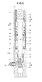
- a front fork 10 (a hydraulic shock absorber) is used in a motor cycle or the like. It is structured, as shown in FIG. 1 to FIG. 4 , such that an inner tube 12 (a vehicle body side tube) in a vehicle body side is slidably inserted into an outer tube 11(a wheel side tube) in which one end is closed and another end is open, in a wheel side.
- An opening end into which the inner tube 12 is inserted in the outer tube 11 is provided with a slide guide 13, a seal spacer 14, an oil seal 15, a stopper ring 16 and a dust seal 17.
- a slide guide 19 is provided in an outer peripheral portion of a lower end which is inserted into the outer tube 11 in the inner tube 12.
- a bolt 21 is inserted into a bottom portion of the outer tube 11 via a copper packing 21A, and a hollow pipe 22 which is fixed by the bolt 21 is provided in a rising manner.
- the bolt 21 is attached by screw to a thread portion in an inner periphery of a contracted portion below a lower end taper portion of the hollow pipe 22.
- An outer periphery of a lower end portion of a cap bolt 23 is attached by screw to an upper end portion of the inner tube 12 via an O-ring 23A, and a spring load adjusting means 30 is provided in a center portion of the cap bolt 23.
- the spring load adjusting means 30 has an adjust bolt 31 which is attached by screw as well as being passed through inner and outer sides of a center portion of the cap bolt 23 via an O-nng 31A.
- a tabular upper spring receiving portion 32 is fixed to an end portion which is inserted into an inner portion of the inner tube 12 while passing through the cap bolt 23 in the adjust bolt 31, and a spring receiving collar 33 is supported in a contact manner to a lower surface of the upper spring receiving portion 32.
- a compression coil spring 35 is interposed between the upper spring receiving portion 32 and the spring receiving collar 33, and a lower spring receiving portion 34 which consists of an upper end surface of an expanded partition wall portion 22A provided in an upper end portion of the hollow pipe 22. An initial load of the compression coil spring 35 is adjusted and set on the basis of a screw motion of the adjust bolt 31.
- the partition wall portion 22A mentioned above is provided in an upper end portion of the hollow pipe 22, and a check valve 24 which comes into slidable contact with an inner periphery of the inner tube 12 is fitted and inserted into an annular groove 22B in an outer periphery of the partition wall portion 22A.
- An oil chamber 25 mentioned below is provided in an outer periphery of a lower portion of the partition wall portion 22A in the hollow pipe 22.
- the check valve 24 consists of a C-shaped piston ring which is loaded to the annular groove 22B in the outer periphery of the partition wall portion 22A of the hollow pipe 22 so as to be movable up and down, comes into slidable contact with the inner periphery of the inner tube 12, and forms am annular flow path 26 with respect to a groove bottom portion of the annular groove 22B.
- the check valve 24 forms and is provided with a notch portion 24A passing through in a diametrical direction in a lower end surface which is closer to the oil chamber 25 within the annular groove 22B of the partition wall portion 22A.
- the check valve 24 moves downward (moves downward in conjunction with a relative downward movement of the inner tube 12 with respect to the hollow pipe 22) in the compression stroke, forms a gap between an upper end surface of the check valve 24 and an upper wall portion of the annular groove 22B of the partition wall portion 22A, and allows oil in an oil reservoir chamber 27 mentioned below above the partition wall portion 22A to flow into the oil chamber 25 (an upper oil chamber 25A) in an outer periphery of the hollow pipe 22 via the annular flow path 26 and the notch portion 24A.
- the check valve 24 moves upward (moves upward in conjunction with a high pressure formation of the upper oil chamber 25A and a relative upward movement of the inner tube 12 with respect to the hollow pipe 22) in the extension stroke, brings the upper end surface of the check valve 24 into close contact with the upper wall portion of the annular groove 22B of the partition wall portion 22A so as to close the valve, and inhibits oil from flowing out of the oil chamber 25 (the upper oil chamber 25A) in the outer periphery of the hollow pipe 22 to the oil reservoir chamber 27 in the upper portion of the partition wall portion 22A.
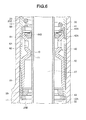
- a piston 40 is provided in an inner periphery of a leading end portion (a lower end portion) which is inserted into the outer tube 11 in the inner tube 12.
- the piston 40 consists of an annular upper piece 41 which is locked to an inner diameter step portion of the inner tube 12, a tubular lower piece 42 which is fixed to the upper piece 41 by a lower end caulking portion 12A of the inner tube 12, and a washer 43.
- a check valve 44 is arranged in an inner periphery of the upper taper portion 42A of the lower piece 42. The check valve 44 will be mentioned later.
- the piston 40 in the leading end portion of the inner tube 12 goes into and out of the oil chamber 25 in the outer periphery of the hollow pipe 22, and divides the oil chamber 25 into upper and lower parts.
- the upper oil chamber 25A is formed by the inner tube 12, the hollow pipe 22, the partition wall portion 22A and the piston 40
- the lower oil chamber 25B is formed by the outer tube 11 in the lower portion of the piston 40 and the hollow pipe 22.
- the oil reservoir chamber 27 running into the upper portion of the inner tube 12 is comparted in the inner periphery of the hollow pipe 22.
- the working fluid is filled in the oil reservoir chamber 27, and an upper portion of the oil reservoir chamber 27 is formed as an air chamber 28.
- the hollow pipe 22 is provided with a volumetric capacity compensating flow path 50 which communicates the oil chamber 25 in the outer periphery of the hollow pipe 22 with the oil reservoir chamber 27 in the inner periphery of the hollow pipe 22 and is set for compensating the oil at the volumetric capacity at which the inner tube 12 goes into and out of the oil chamber 25 in the outer periphery of the hollow pipe 22.
- the volumetric capacity compensating flow path 50 will be mentioned later.
- annular gap chamber 60 sandwiched between a slide guide 13 which is fixed to an inner periphery of the outer tube 11, and a slide guide 19 which is fixed to an outer periphery of the inner tube 12.
- At least one hole 61 is pierced in a portion in which the piston 40 is provided in the inner tube 12.
- At least one hole 62 is pierced in a lower piece 42 of the piston 40, and the annular gap chamber 60 is communicated with the oil chamber 25 (the upper oil chamber 25A and the lower oil chamber 25B) in the outer periphery of the hollow pipe 22 by these holes 61 and 62.
- the working fluid is supplied to the annular gap chamber 60, and lubrication and volumetric capacity compensation of the slide guides 13 and 19 are carried out.
- the check valve 44 provided in the piston 40 mentioned above is provided between the hole 61 of the inner tube 12 and the hole 62 of the lower piece 42 of the piston 40 which are communicated with the annular gap chamber 60, and the upper oil chamber 25A in the outer periphery of the hollow pipe 22.
- the check valve 44 is energized by a spring 44A formed as a disc spring (may be formed as a coil) which is supported its back face by the upper piece 41.
- a taper surface thereof is seated on a taper surface of the upper taper portion 42A of the lower piece 42, and an annular gap 44B is formed between an inner periphery thereof and an outer periphery of the hollow pipe 22.
- the check valve 44 is opened on the basis of a hydraulic pressure of the lower oil chamber 25B which comes to a high pressure, and allows the oil to flow into the upper oil chamber 25A from the lower oil chamber 25B, in the compression stroke.
- the check valve 44 seats on the upper taper portion 42A of the lower piece 42 on the basis of a hydraulic pressure of the upper oil chamber 25A which comes to a high pressure, and narrows down the oil flowing out of the upper oil chamber 25A by the annular gap 44B, in the extension stroke.
- the hollow pipe 22 is provided in a piercing manner just below the partition wall portion 22A with an orifice 45 which makes a part of the oil in the upper oil chamber 25A coming to a high pressure in the extension stroke flow out to the oil reservoir chamber 27 in the inner periphery of the hollow pipe 22.
- a rebound spring 36 at a time of a maximum extension which corresponds to a stroke end in the extension stroke is provided between the upper piece 41 of the piston 40 which is provided in the inner tube 12, and the partition wall portion 22A which is provided in the hollow pipe 22, and controls a maximum extension stroke.
- an oil lock piece 37 is pinched between a lower end portion of the hollow pipe 22 and a bottom portion of the outer tube 11.
- a maximum compression stroke is controlled by pressurizing the working fluid in the periphery of the oil lock piece 37 by an oil lock collar 38 which is provided in a lower end inner periphery of the lower piece 42 of the piston 40 at a time of a maximum compression which corresponds to a stroke end of the compression stroke.
- the oil lock collar 38 mentioned above interposing a micro gap with respect to the inner periphery of the lower piece 42 is fitted between the lower piece 42 of the piston 40 and the washer 43 so as to be movable up and down.
- the oil lock collar 38 is fitted via a micro gap with respect to the oil lock piece 37 provided in the side of the hollow pipe 22, in the vicinity of the maximum compression of the front fork 10, and buffers at a time of the minimum compression. Further, at a time of the extension from the maximum compression state, it moves downward so as to open an oil path consisting of a micro gap in an outer periphery of the oil lock collar 38.
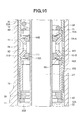
- the front fork 10 is provided with the following structure for improving a response of generation of the damping force, and improving a sealing performance of the annular gap chamber 60 between the outer tube 11 and the inner tube 12.
- the front fork 10 is provided with a throttle flow path 70 which narrows down the oil flowing out of the lower oil chamber 25B in a whole region from a stroke initial time of the compression stroke to a stroke end, and inhibits the pressure in the lower oil chamber 25B from applying to the annular gap chamber 60, between the hole 61 of the inner tube 12 which is communicated with the annular gap chamber 60, and the hole 62 of the lower piece 42 of the piston 40, and the lower oil chamber 25B in the outer periphery of the hollow pipe 22.
- the throttle flow path 70 in accordance with the present embodiment is provided in an intermediate portion (a portion coming closer to the lower oil chamber 25B than the hole 62) of the lower piece 42 of the piston 40, and is constructed by a contracted portion 71 obtained by reducing an inner diameter of the intermediate portion of the lower piece 42.
- An annular gap flow path which the reduced inner diameter of the contracted portion 71 forms with respect to the outer periphery of the hollow pipe 22 comes to the throttle flow path 70.
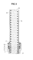
- the front fork 10 is provided with the volumetric capacity compensating flow path 50 which communicates the oil chamber 25 and the oil reservoir chamber 27.
- the volumetric capacity compensating flow path 50 is set for compensating the oil at the volumetric capacity at which the inner tube 12 goes into and out of the oil chamber 25 in the outer periphery of the hollow pipe 22, in the lower end portion of the hollow pipe 22 which is provided in a rising manner by the bolt 21 in the bottom portion of the outer tube 11, and the oil lock piece 37.
- the volumetric capacity compensating flow path 50 consists of holes 51 and a plurality of grooves 52.
- the holes 51 are pierced at a plurality of positions in a peripheral direction of the lower end taper portion of the hollow pipe 22 surrounded by the oil lock piece 37 when the lower end taper portion of the hollow pipe 22 is fitted to the upper end inner diameter portion of the oil lock piece 37.
- the plurality of grooves 52 are formed at a plurality of positions in a peripheral direction of an upper end inner diameter portion of the oil lock piece 37 to which the lower end taper portion of the hollow pipe 22 is fitted.
- the volumetric capacity compensating flow path 50 is provided further with an annular check valve 53 which is attached to an outer periphery of the hollow pipe 22.
- the annular check valve 53 forms an annular flow path 53A which is along a peripheral direction of an inner diameter of an annular body with respect to the outer peripheriy of the hollow pipe 22 ( FIG. 8 ).
- the annular check valve 53 forms three circular arc shaped annular flow paths 53A which are adjacent to each other in the peripheral direction.
- the annular check valve 53 can switch to a valve close state in which a washer 55 locked to a stop ring 54 provided in the outer periphery of the hollow pipe 22 elastically comes into contact with an upper end surface of the oil lock piece 37 by a backup valve spring 56, and to a valve open state in which it is isolated from the upper end surface of the oil lock piece 37 on the basis of a negative pressure of the lower oil chamber 25B.
- Reference numeral 57 denotes a come-off preventing stop ring of the annular check valve 53 or the like which is embedded in the hollow pipe 22.
- the annular check valve 53 is opened in the extension stroke so as to allow the oil at the going-cut volume of the inner tube 12 to be replenished to the lower oil chamber 25B from the oil reservoir chamber 27 via the volumetric capacity compensating flow path 50 (the hole 51 and the groove 52). Further, the annular check valve 53 is closed in the compression stroke so as to narrow down the oil at the inserting volume of the inner tube 12 by the annular flow path 53A, and discharge to the oil reservoir chamber 27 from the lower oil chamber 25B via the volumetric capacity compensating flow path 50 (the hole 51 and the groove 52).
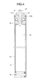
- the front fork 10 is provided with a compression side damping force adjusting means 90 in a bypass flow path 80 which communicates the oil chamber 25 and the oil reservoir chamber 27 while bypassing the volumetric capacity compensating flow path 50.
- the bypass flow path 80 discharges the oil at the volumetric capacity at which the inner tube 12 goes into the oil chamber 25 in the compression stroke from the lower oil chamber 25B to the oil reservoir chamber 27.
- the bypass flow path 80 is constructed by a hole-like flow path 81 which is pierced in the lower portion of the outer tube 11, and a hole-like flow path 82 which is pierced in the bolt 21.
- the compression side damping force adjusting means 90 narrows down the oil which is discharged to the oil reservoir chamber 27 from the lower oil chamber 25B in the compression stroke and finely adjusts the compression side damping force, by making a needle 92 which is installed to a cap 91 attached by screw to the lower portion of the outer tube 11 go into and out of the hole-like flow path 81 of the outer tube 11, and adjusting so as to narrow down a flow path area of the hole-like flow path 81.
- a shock exposed to the vehicle is absorbed and reduced by the compression coil spring 35 and the air spring of the air chamber 28, and a vibration of the compression coil spring 35 in conjunction with the absorption of the shock is damped on the basis of the following damping action.
- the damping force caused by the passage resistance generated in the annular flow path 53A or the passage resistance generated in the hole-like flow path 81 which is narrowed down by the compression side damping force adjusting means 90, is generated, at a time when the oil at the cross sectional area x stroke of the inner tube 12 moves to the annular flow path 53A of the annular check valve 53 which is provided in the volumetric capacity compensating flow path 50 from the lower oil chamber 25B, or to the oil reservoir chamber 27 through the bypass flow path 80 of the volumetric capacity compensating flow path 50.
- the oil in the oil chamber 25 is replenished to the annular gap chamber 60 between the outer tube 11 and the inner tube 12, which is expanded by the downward movement of the inner tube 12, from the hole 61 of the inner tube 12 and the hole 62 of the piston 40.
- the throttle flow path 70 inhibits the high pressure in the lower oil chamber 25B from being applied to the seal member (the oil seal 15) in the annular gap chamber 60. In accordance with this, it is possible to prevent an oil leakage without raising pressure resistance of the seal member (the oil seal 15), and it is possible to improve sealing performance for the annular gap chamber 60.
- the annular flow path 53A of the annular check valve 53 applies the damping characteristic of the direct proportional characteristic (the viscous resistance type) to the oil which is discharged to the oil reservoir chamber 27 from the lower oil chamber 25B via the volumetric capacity compensating flow path 50, in the compression stroke. If the flow path which is discharged to the oil reservoir chamber 27 from the lower oil chamber 25B via the volumetric capacity compensating flow path 50 is constructed by a round hole which is pierced in the hollow pipe 22, the damping characteristic comes to the square hole characteristic.
- the direct proportional characteristic the viscous resistance type
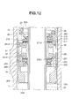
- a different point of an embodiment 2 from the embodiment 1 exists in a structure in which a check valve 110 which allows an inflow of the oil to the lower oil chamber 25B in an extension stroke (a broken line in FIG. 9 ) and narrows down the oil flowing out of the lower oil chamber 25B in a compression stroke (a solid line in FIG. 9 ) is provided between the hole 61 of the inner tube 12 which is communicated with the annular gap chamber 60, and the hole 62 of the lower piece 42 of the piston 40, and the lower oil chamber 25B in the outer periphery of the hollow pipe 22, and a throttle flow path 111 substituting for the throttle flow path 70 mentioned above is formed by the check valve 110.
- the check valve 110 consists of the same structure as the check valve 44 which is provided closer to the upper oil chamber 25A than the hole 62 communicating with the annular gap chamber 60 of the piston 40.
- the lower piece 42 provided between the upper piece 41 of the piston 40.
- the washer 43 consists of a piston body 101, a valve stopper 102 and a spacer 103.
- the same oil lock collar 38 as that in the embodiment 1 is fitted and inserted between the spacer 103 and the washer 43.
- the check valve 44 in the embodiment 1 is arranged in an inner periphery of an upper taper portion 101A of the piston body 101 of the piston 40, and the check valve 110 is arranged in an inner periphery of a lower taper portion 101B of the piston body 101.
- the piston body 101 is provided with the hole 62 which is provided in the lower piece 42 in the embodiment 1.
- the check valve 110 is arranged in an inner periphery of the lower taper portion 101B of the piston body 101 of the piston 40.
- the check valve 110 is energized by a spring 104 which is formed as a disc spring (may be formed as a coil) and is supported at its back face by the valve stopper 102 of the piston 40.
- the check valve 110 is structured such that a taper surface thereof is seated on a taper surface of the lower taper portion 101B of the piston body 101.
- An annular gap 110A is formed between an inner periphery thereof and an outer periphery of the hollow pipe 22.
- the check valve 110 is structured such as to form a throttle flow path 111 having a fixed opening degree by the annular gap 110A.
- the check valve 110 is opened on the basis of a hydraulic pressure of the upper oil chamber 25A which comes to a high pressure in the extension stroke, and allows the inflow of the oil to the lower oil chamber 25B from the upper oil chamber 25A.
- the compression stroke it comes into close contact with the lower taper portion 101B of the piston body 101 on the basis of the hydraulic pressure of the low oil chamber 25B coming to a high pressure, and narrows down the oil flowing out of the lower oil chamber 25B by the annular gap 110A (the throttle flow path 111).
- the check valve 110 which allows the inflow of the oil to the lower oil chamber 25B in the extension stroke, and narrows down the oil flowing out of the lower oil chamber 25B in the compression stroke, is provided between the hole 61 which is provided in the inner tube 12 and is communicated with the annular gap chamber 60, and the lower oil chamber 25B in the outer periphery of the hollow pipe 22.
- the throttle flow path 111 substituting for the throttle flow path 70 mentioned above is formed by the check valve 110.
- the throttle flow path 111 of the check valve 110 serves as the throttle flow path 70 mentioned above in the compression stroke, thereby improving the response of the compression side damping force as mentioned above. Even in the case that the compression side damping force is set high, it is possible to improve the sealing performance of the annular gap chamber 60.
- the upper limit of the extension side damping force is not decided by the pressure resistance of the seal member (the oil seal 15), and it is possible to improve the sealing performance of the annular gap chamber 60.
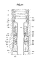
- a different point of an embodiment 3 from the embodiment 2 exists in a structure in which the check valve 44 and the check valve 110 provided in the piston 40 are changed to a check valve 210 and a check valve 220 which consist of disc valves 211 and 221.
- the piston 40 in accordance with the embodiment 2 which is caulked and fixed to the leading end portion of the inner tube 12 consists of a piston body 201, upper and lower valve stoppers 202 and 203 thereof, and a spacer 204.
- the piston body 201 is provided with the hole 62 in accordance with the embodiment 2.
- the check valve 210 is provided between the piston body 201 and the upper valve stopper 202, and consists of a disc valve 211 which opens and closes a flow path 201A communicating with the hole 62 of the piston body 201, a valve spring 212 which energizes the disc valve 211 in a close side, and a valve piece 213.
- the check valve 210 lifts up the disc valve 211 on the basis of a hydraulic pressure of the lower oil chamber 25B coming to the high pressure so as to be opened in a compression stroke (a solid line in FIG. 11 ), thereby allowing an inflow of the oil from the lower oil chamber 25B to the upper oil chamber 25A.
- the check valve 210 flexibly deforms the disc 211 on the basis of the hydraulic pressure in the upper oil chamber 25A coming to the high pressure so as to open the gap coming to a throttle flow path 211A in a extension stroke (a broken line in FIG. 11 ), thereby narrowing down the oil flowing out of the upper oil chamber 25A by the throttle flow path 211A.
- the check valve 220 is provided between the piston body 201 and the lower valve stopper 203, and consists of a disc valve 221 which opens and closes a flow path 201B communicating with the hole 62 of the piston body 201, a valve spring 222 which energizes the disc valve 221 in a close side, and a valve piece 223.
- the check valve 220 lifts up the disc valve 221 on the basis of a hydraulic pressure of the upper oil chamber 25A coming to the high pressure so as to be opened in the expression stroke, thereby allowing an inflow of the oil from the upper oil chamber 25A to the lower oil chamber 25B.
- the throttle flow path 221A of the check valve 220 consists of the throttle flow path 221A which changes the opening degree by opening and closing the disc valve 221. In accordance with this, a setting and adjusting width of the compression side damping force characteristic in the compression stroke becomes larger.
- a front fork comprising: an inner tube in a vehicle body side being slidably inserted into an outer tube in a wheel side.
- a hollow pipe has a partition wall portion coming into slidable contact with an inner periphery of the inner tube being provided in a rising manner in a bottom portion within the outer tube.
- An oil chamber in which a piston provided in an inner periphery of a leading end portion of the inner tube moves back and forth is provided in an outer periphery of the hollow pipe, and the oil chamber being comparted into an upper oil chamber above the piston and a lower oil chamber below the piston by the piston.
- An oil reservoir chamber runs into an upper portion of the inner tube being defined in an inner periphery of the hollow pipe, and an upper portion of the oil reservoir chamber being formed as an air chamber.
- the oil chamber in the outer periphery of the hollow pipe is communicated with the oil reservoir chamber in the inner periphery of the hollow pipe.
- the hollow pipe is provided with a volumetric capacity compensating flow path for compensating an oil at a volumetric capacity at which the inner tube goes into and out of the oil chamber in the outer periphery of the hollow pipe.
- An annular gap chamber sandwiched by a slide guide is fixed to an inner periphery of the outer tube and a slide guide fixed to an outer periphery of the inner tube.
- the annular gap chamber is provided between the outer tube and the inner tube, and the inner tube is provided with a hole which communicates the annular gap chamber with the oil chamber in the outer periphery of the hollow pipe.
- a throttle flow path is provided between a hole which is provided in the inner tube and is communicated with the annular gap chamber, and a lower oil chamber in the outer periphery of the hollow pipe. Accordingly, it is possible to improve a response of generation of a damping force, and improve a sealing performance of an annular gap chamber between an outer tube and an inner tube, in a front fork.
Applications Claiming Priority (1)
| Application Number | Priority Date | Filing Date | Title |
|---|---|---|---|
| JP2011188010A JP5873666B2 (ja) | 2011-08-30 | 2011-08-30 | フロントフォーク |
Publications (2)
| Publication Number | Publication Date |
|---|---|
| EP2565490A2 true EP2565490A2 (de) | 2013-03-06 |
| EP2565490A3 EP2565490A3 (de) | 2018-01-03 |
Family
ID=45936869
Family Applications (1)
| Application Number | Title | Priority Date | Filing Date |
|---|---|---|---|
| EP12160623.0A Pending EP2565490A3 (de) | 2011-08-30 | 2012-03-21 | Vorderradgabel |
Country Status (4)
| Country | Link |
|---|---|
| US (1) | US8641022B2 (de) |
| EP (1) | EP2565490A3 (de) |
| JP (1) | JP5873666B2 (de) |
| CN (1) | CN102966696B (de) |
Cited By (1)
| Publication number | Priority date | Publication date | Assignee | Title |
|---|---|---|---|---|
| WO2015088457A1 (en) * | 2013-12-13 | 2015-06-18 | Turk Traktor Ve Ziraat Makinalari Anonim Sirketi | Dampening tie member |
Families Citing this family (6)
| Publication number | Priority date | Publication date | Assignee | Title |
|---|---|---|---|---|
| JP6012449B2 (ja) * | 2012-12-14 | 2016-10-25 | 株式会社ショーワ | 自動二輪車の車高調整装置 |
| JP6278784B2 (ja) * | 2014-03-28 | 2018-02-14 | 株式会社ショーワ | フロントフォーク |
| CN104405814A (zh) * | 2014-11-21 | 2015-03-11 | 重庆隆鑫发动机有限公司 | 用于减震阻尼的调节组件 |
| CN104405818B (zh) * | 2014-11-21 | 2017-12-05 | 重庆隆鑫发动机有限公司 | 可调式减震器 |
| CN104728336B (zh) * | 2015-04-02 | 2017-03-08 | 重庆弓虽工页机械有限公司 | 摩托车倒置式前减震装置 |
| US20190092116A1 (en) * | 2017-09-28 | 2019-03-28 | Saint-Gobain Performance Plastics Pampus Gmbh | Suspension assembly and method of making and using the same |
Citations (1)
| Publication number | Priority date | Publication date | Assignee | Title |
|---|---|---|---|---|
| JP2002161940A (ja) | 2000-11-24 | 2002-06-07 | Kayaba Ind Co Ltd | フロントフォーク |
Family Cites Families (10)
| Publication number | Priority date | Publication date | Assignee | Title |
|---|---|---|---|---|
| JPH0658360A (ja) * | 1992-08-06 | 1994-03-01 | Kayaba Ind Co Ltd | 車両用油圧緩衝器 |
| US6296092B1 (en) * | 1998-10-28 | 2001-10-02 | Fox Factory, Inc. | Position-sensitive shock absorber |
| US7290643B2 (en) * | 2003-12-17 | 2007-11-06 | Nobuaki Fujita | Front fork in two-wheeled motor vehicle or the like |
| JP2005201345A (ja) * | 2004-01-14 | 2005-07-28 | Showa Corp | 自動二輪車等のフロントフォーク |
| JP2005299913A (ja) * | 2004-03-17 | 2005-10-27 | Showa Corp | 二輪車等のフロントフォーク |
| JP2006183801A (ja) * | 2004-12-28 | 2006-07-13 | Showa Corp | 二輪車等のフロントフォーク |
| JP2007205398A (ja) * | 2006-01-31 | 2007-08-16 | Showa Corp | ばね受構造 |
| JP2008057590A (ja) * | 2006-08-29 | 2008-03-13 | Showa Corp | フロントフォーク |
| JP5582758B2 (ja) * | 2008-11-27 | 2014-09-03 | 株式会社ショーワ | フロントフォークのオイルロック装置 |
| JP5383451B2 (ja) * | 2009-11-26 | 2014-01-08 | 株式会社ショーワ | 油圧緩衝器 |
-
2011
- 2011-08-30 JP JP2011188010A patent/JP5873666B2/ja active Active
-
2012
- 2012-03-16 CN CN201210071430.3A patent/CN102966696B/zh active Active
- 2012-03-21 EP EP12160623.0A patent/EP2565490A3/de active Pending
- 2012-03-23 US US13/428,976 patent/US8641022B2/en active Active
Patent Citations (1)
| Publication number | Priority date | Publication date | Assignee | Title |
|---|---|---|---|---|
| JP2002161940A (ja) | 2000-11-24 | 2002-06-07 | Kayaba Ind Co Ltd | フロントフォーク |
Cited By (1)
| Publication number | Priority date | Publication date | Assignee | Title |
|---|---|---|---|---|
| WO2015088457A1 (en) * | 2013-12-13 | 2015-06-18 | Turk Traktor Ve Ziraat Makinalari Anonim Sirketi | Dampening tie member |
Also Published As
| Publication number | Publication date |
|---|---|
| JP5873666B2 (ja) | 2016-03-01 |
| EP2565490A3 (de) | 2018-01-03 |
| US20130048452A1 (en) | 2013-02-28 |
| US8641022B2 (en) | 2014-02-04 |
| CN102966696A (zh) | 2013-03-13 |
| CN102966696B (zh) | 2016-03-16 |
| JP2013050157A (ja) | 2013-03-14 |
Similar Documents
| Publication | Publication Date | Title |
|---|---|---|
| US8641022B2 (en) | Front fork | |
| KR101439541B1 (ko) | 유체압 완충기 | |
| US9206876B2 (en) | Damping force control type shock absorber | |
| KR101420441B1 (ko) | 감쇠력 조정식 유체압 완충기 | |
| KR101639506B1 (ko) | 완충기의 감쇠 밸브 | |
| JP4985984B2 (ja) | 減衰力調整式緩衝器 | |
| US20120247890A1 (en) | Hydraulic shock absorber | |
| US20080236966A1 (en) | Damping force adjustable fluid pressure shock absorber | |
| US20060054435A1 (en) | Hydraulic shock absorber | |
| US11473645B2 (en) | Hydraulic shock-absorber with hydraulic stop member and adjustment device | |
| US10465765B2 (en) | Damping force adjustment mechanism | |
| JP6277447B2 (ja) | 油圧緩衝器 | |
| CN111630295B (zh) | 阻尼阀和缓冲器 | |
| JP5368917B2 (ja) | 減衰バルブ | |
| CN107614924B (zh) | 减震器 | |
| JPWO2017090492A1 (ja) | 減衰力調整式緩衝器 | |
| KR20190121826A (ko) | 완충기 | |
| KR20190109469A (ko) | 완충기 | |
| US9694871B2 (en) | Shock absorber | |
| JP4898613B2 (ja) | 緩衝器 | |
| US7240775B2 (en) | Shock absorber | |
| US9849934B2 (en) | Shock absorber | |
| JP6464036B2 (ja) | 減衰バルブ及び緩衝器 | |
| JP2008240745A (ja) | 油圧緩衝器 | |
| JP7154199B2 (ja) | 緩衝器 |
Legal Events
| Date | Code | Title | Description |
|---|---|---|---|
| PUAI | Public reference made under article 153(3) epc to a published international application that has entered the european phase |
Free format text: ORIGINAL CODE: 0009012 |
|
| AK | Designated contracting states |
Kind code of ref document: A2 Designated state(s): AL AT BE BG CH CY CZ DE DK EE ES FI FR GB GR HR HU IE IS IT LI LT LU LV MC MK MT NL NO PL PT RO RS SE SI SK SM TR |
|
| AX | Request for extension of the european patent |
Extension state: BA ME |
|
| PUAL | Search report despatched |
Free format text: ORIGINAL CODE: 0009013 |
|
| AK | Designated contracting states |
Kind code of ref document: A3 Designated state(s): AL AT BE BG CH CY CZ DE DK EE ES FI FR GB GR HR HU IE IS IT LI LT LU LV MC MK MT NL NO PL PT RO RS SE SI SK SM TR |
|
| AX | Request for extension of the european patent |
Extension state: BA ME |
|
| RIC1 | Information provided on ipc code assigned before grant |
Ipc: B62K 25/08 20060101ALI20171129BHEP Ipc: F16F 9/18 20060101ALI20171129BHEP Ipc: F16F 9/516 20060101ALI20171129BHEP Ipc: F16F 9/16 20060101ALI20171129BHEP Ipc: F16F 9/34 20060101AFI20171129BHEP |
|
| STAA | Information on the status of an ep patent application or granted ep patent |
Free format text: STATUS: REQUEST FOR EXAMINATION WAS MADE |
|
| 17P | Request for examination filed |
Effective date: 20180621 |
|
| RBV | Designated contracting states (corrected) |
Designated state(s): AL AT BE BG CH CY CZ DE DK EE ES FI FR GB GR HR HU IE IS IT LI LT LU LV MC MK MT NL NO PL PT RO RS SE SI SK SM TR |
|
| STAA | Information on the status of an ep patent application or granted ep patent |
Free format text: STATUS: EXAMINATION IS IN PROGRESS |
|
| 17Q | First examination report despatched |
Effective date: 20200512 |
|
| STAA | Information on the status of an ep patent application or granted ep patent |
Free format text: STATUS: EXAMINATION IS IN PROGRESS |
|
| STAA | Information on the status of an ep patent application or granted ep patent |
Free format text: STATUS: EXAMINATION IS IN PROGRESS |
|
| RAP1 | Party data changed (applicant data changed or rights of an application transferred) |
Owner name: HITACHI ASTEMO, LTD. |