EP2565332A1 - Construction machinery - Google Patents
Construction machinery Download PDFInfo
- Publication number
- EP2565332A1 EP2565332A1 EP11786644A EP11786644A EP2565332A1 EP 2565332 A1 EP2565332 A1 EP 2565332A1 EP 11786644 A EP11786644 A EP 11786644A EP 11786644 A EP11786644 A EP 11786644A EP 2565332 A1 EP2565332 A1 EP 2565332A1
- Authority
- EP
- European Patent Office
- Prior art keywords
- door
- operator
- cab
- edge portion
- outwardly
- Prior art date
- Legal status (The legal status is an assumption and is not a legal conclusion. Google has not performed a legal analysis and makes no representation as to the accuracy of the status listed.)
- Granted
Links
Images


Classifications
-
- B—PERFORMING OPERATIONS; TRANSPORTING
- B62—LAND VEHICLES FOR TRAVELLING OTHERWISE THAN ON RAILS
- B62D—MOTOR VEHICLES; TRAILERS
- B62D33/00—Superstructures for load-carrying vehicles
- B62D33/06—Drivers' cabs
- B62D33/0617—Drivers' cabs for tractors or off-the-road vehicles
-
- B—PERFORMING OPERATIONS; TRANSPORTING
- B60—VEHICLES IN GENERAL
- B60R—VEHICLES, VEHICLE FITTINGS, OR VEHICLE PARTS, NOT OTHERWISE PROVIDED FOR
- B60R3/00—Arrangements of steps or ladders facilitating access to or on the vehicle, e.g. running-boards
-
- E—FIXED CONSTRUCTIONS
- E02—HYDRAULIC ENGINEERING; FOUNDATIONS; SOIL SHIFTING
- E02F—DREDGING; SOIL-SHIFTING
- E02F3/00—Dredgers; Soil-shifting machines
- E02F3/04—Dredgers; Soil-shifting machines mechanically-driven
- E02F3/28—Dredgers; Soil-shifting machines mechanically-driven with digging tools mounted on a dipper- or bucket-arm, i.e. there is either one arm or a pair of arms, e.g. dippers, buckets
- E02F3/30—Dredgers; Soil-shifting machines mechanically-driven with digging tools mounted on a dipper- or bucket-arm, i.e. there is either one arm or a pair of arms, e.g. dippers, buckets with a dipper-arm pivoted on a cantilever beam, i.e. boom
- E02F3/32—Dredgers; Soil-shifting machines mechanically-driven with digging tools mounted on a dipper- or bucket-arm, i.e. there is either one arm or a pair of arms, e.g. dippers, buckets with a dipper-arm pivoted on a cantilever beam, i.e. boom working downwardly and towards the machine, e.g. with backhoes
- E02F3/325—Backhoes of the miniature type
-
- E—FIXED CONSTRUCTIONS
- E02—HYDRAULIC ENGINEERING; FOUNDATIONS; SOIL SHIFTING
- E02F—DREDGING; SOIL-SHIFTING
- E02F9/00—Component parts of dredgers or soil-shifting machines, not restricted to one of the kinds covered by groups E02F3/00 - E02F7/00
- E02F9/16—Cabins, platforms, or the like, for drivers
- E02F9/163—Structures to protect drivers, e.g. cabins, doors for cabins; Falling object protection structure [FOPS]; Roll over protection structure [ROPS]
Definitions
- This invention relates to a construction machine, such as a compact excavator, provided with an operator' s cab having a door that can closably open an ingress/egress opening.
- Patent Document 1 As a conventional technology of this kind, there is a hydraulic excavator disclosed in Patent Document 1.
- This hydraulic excavator is provided with an upperstructure, working equipment attached to the upperstructure, an operator's cab mounted on the upperstructure and having a door capable of closably opening an ingress/egress opening, and a step arranged at the ingress/egress opening of the operator's cab to facilitate ingress to and egress from the operator's cab.
- a seat In the operator's cab, a seat is arranged, and further, a floor is arranged on a lower and front side of the seat.
- the floor is formed of a flat part arranged on a front side of the seat and a stepped part arranged in conjunction with the flat part and on a side of the ingress/egress opening, and the stepped part makes up the above-mentioned step.
- the stepped part that makes up the step is arranged such that it is located inside the door when the door of the operator's cab is in a closed position. In other words, the stepped part that makes up the step is arranged within the operator's cab.
- Patent Document 1 JP-A-2005-226307
- the shape or dimensions of the above-mentioned stepped part have to be unavoidably set small to secure a sufficient foot area in the operator's cab.
- the ingress to and egress from the operator's cab via the stepped part, that is, the step may not be made with ease.
- the stepped part which makes up the step arranged in the operator's cab, toward the door, and moreover, to form the stepped part large enough to extend along the whole area of the closed door so that the ingress to and egress from the operator's cab can be facilitated even in the case a small construction machine such as a compact excavator.
- modifications provide the operator's cab with a shell profile that pillars of the operator's cab, said pillars being arranged on the side of the working equipment, that is, front pillars protrude out to a greater extent than before.
- Such a profile means that the operator's cab protrudes outside a swing radius of the upperstructure, which is fundamentally required for a small construction machine such as a compact excavator and is of a dimension not greater than the width of the construction machine. Therefore, the swing radius of the upperstructure becomes greater than the fundamentally-required swing radius, imposes a restriction on the working environment, and may interfere with a variety of work to be performed by the working equipment of the small construction machine such as the compact excavator.
- step may also be contemplated to set the shape or dimensions of the step greater by forming the step such that the step extends outwards from the lower end of the door and is exposed to the outside. If the step is constructed as described above and the construction machine is placed in a cold district to perform work, the step extends out from the door, snow may fall on the externally-exposed part of the step, and the fallen snow may freeze. If such freezing of fallen snow takes place, the door tends to become hardly openable or closable.
- the present invention has as an obj ect thereof the provision of a construction machine with a step arranged in an operator's cab, which makes it possible to enlarge the shape or dimensions of the step without increasing a swing radius.
- the present invention is characterized in that, in a construction machine provided with an upperstructure, working equipment attached to the upperstructure, an operator's cab mounted on the upperstructure and having a door capable of closably opening an ingress/egress opening, and a step arranged at the ingress/egress opening to facilitate ingress to and egress from the operator's cab, the step is provided at a part thereof with an outwardly-extending edge portion that extends out beyond an opening plane forming the ingress/egress opening, and the door is provided at a part thereof with a convex part that covers the outwardly-extending edge portion of the step when the door is in a closed position.
- the outwardly-extending edge portion that extends out beyond the opening plane forming the ingress/egress opening of the operator' s cab is arranged only at the specific part of the step, so that the step can be provided with the outwardly-extending edge portion without altering the shell profile of the operator's cab. Therefore, the shape or dimensions of the step can be made larger without increasing the swing radius. Further, the outwardly-extending edge portion arranged at the step is covered by the convex part arranged at the specific part of the door when the door has been closed, and therefore, the whole step including the outwardly-extending edge portion can be positioned in the operator's cab. Even when the construction machine is placed in a cold district where snow falls, it is possible to avoid such a situation that fallen snow would freeze on the step.
- a floor of the operator's cab is formed of a flat part arranged on a front side of a seat and a stepped part arranged in conjunction with the flat part and on a side of the ingress/egress opening, a flange part which lies in a same plane as the stepped part of the floor is arranged in conjunction with the stepped part and in the operator's cab, the step comprises the stepped part of the floor and the flange part, and the flange part is provided with the outwardly-extending edge portion.
- the present invention may also be characterized in that in the above-described invention, the operator' s cab has a front pillar arranged on a side of the working equipment and a door mount pillar with the door swingably attached thereto, and the front pillar and door mount pillar are arranged such that the ingress/egress opening is flanked therebetween, and the front pillar is provided with a recessed portion to receive therein a side edge portion of the door when the door is closed.
- the side edge portion of the door is received in the recessed portion of the front pillar when the door is closed. Therefore, the side edge portion of the door is not located on a side outer than the front pillar, thereby contributing to the maintenance of the swing radius as a fundamental requirement.
- the present invention may also be characterized in that in the above-described invention, the construction machine is a compact excavator, the outwardly-extending edge portion of the flange part is provided on a front-pillar side edge thereof with a bent portion formed such that the bent portion becomes closer to the opening plane as it approaches the front pillar, and the convex part of the door is provided at an edge portion thereof, which is located on a side closer to the front pillar when the door has been closed, with a bent portion located opposite the bent portion of the outwardly-extending edge portion when the door has been closed, and the bent portion of the outwardly-extending edge portion of the door forms a relief recess to avoid an interference with an exterior cover of the upperstructure upon opening of the door.
- the bent portion of the outwardly-extending edge portion of the door forms the relief recess that avoids an interference with the exterior cover which makes up the upperstructure. It is, therefore, possible to prevent damage to the door and exterior cover, which may occur in association with opening of the door.
- the present invention makes it possible to provide the step with the outwardly-extending edge portion without altering the shell profile of the operator's cab.
- the shape or dimensions of the step can be enlarged without making the swing radius greater.
- the outwardly-extending edge portion of the flange part is covered by the convex part arranged at the door when the door has been closed. It is, therefore, possible to avoid such a situation that fallen snow would freeze on the step even when the construction machine is placed in a cold district where snow falls. Accordingly, the construction machine according to the present invention does not cause the situation that the door would become unopenable due to frozen snow, and can realize smooth opening and closure of the door.
- FIG. 1 is a side view showing a compact excavator as an embodiment of the construction machine according to the present invention
- FIG. 2 is a perspective view showing an operator's cab arranged in the compact excavator depicted in FIG. 1 .
- the construction machine of this embodiment is constructed as a compact excavator which is one type of a small construction machine.
- This compact excavator is provided with a travel base 1 having a pair of left and right crawler tracks 1a, an upperstructure 2 mounted on the travel base 1, and working equipment 3 attached to the upperstructure 2 tiltably in an up-and-down direction.
- the working equipment 3 includes a boom 3a attached to the upperstructure 2, an arm 3b connected to a free end of the boom 3a, and a bucket 3c connected to a free end of the arm 3b.
- an operator's cab 6 is mounted on the upperstructure 2, on the upperstructure 2, an operator's cab 6 is mounted.
- the operator's cab 6 houses a seat 4, and has a door 5 that can closably open an ingress/egress opening.
- Also mounted on the upperstructure 2 include an engine compartment 9 housing an engine 7, unillustrated pumps and the like and externally covered by an exterior cover 8, and a counterweight 10 for ensuring static balance.
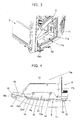
- FIG. 3 is a fragmentary perspective view showing the operator's cab depicted in FIG. 2 , in which a door is in a closed position
- FIG. 4 is a partially cross-sectional plan view showing the operator's cab depicted in FIG. 2 , in which the door is in the closed position
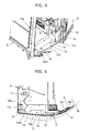
- FIG. 5 is a fragmentary perspective view showing the operator's cab depicted in FIG. 2 , in which the door is in an open position
- FIG. 6 is a partially cross-sectional plan view showing the operator's cab depicted in FIG. 2 , in which the door is in the open position.
- the compact excavator according to this embodiment is provided, at a part of a step that facilitates the ingress to and egress from the operator's cab 6, with an outwardly-extending edge portion 12a that extends out beyond an opening plane 16 forming an ingress/egress opening 20 of the operator's cab 6.
- a floor 11 of the operator's cab 6 includes a flat part 11a arranged on a front side of the above-mentioned seat 4 and a stepped part 11b arranged in conjunction with the flat part 11a, at a position lower than the flat part 11a and on a side of the ingress/egress opening.
- a flange part 12 which lies in a same plane as the stepped part 11b of the floor 11 is arranged in conjunction with the stepped part 11b and in the operator's cab 6, the above-mentioned step is formed of the stepped part 11b of the floor 11 and the flange part 12, and the flange part 12 is provided with the outwardly-extending edge portion 12a that extends out beyond the opening plane 16 forming the ingress/egress opening 20 depicted in FIG. 4 .
- the flange part 12 is detachably secured by a pair of bolts 14 on a frame that makes up the operator's cab 6.
- An end face of a primary portion of the outwardly-extending edge portion 12a arranged on the flange part 12 is formed, for example, in a linear shape extending in a horizontal plane.
- the operator's cab 6 has a pillar arranged on a side of the working equipment, i.e., a front pillar 15 and another pillar with the door 5 swingably attached thereto via hinges 18, i.e., a door mount pillar 13, and the front pillar 15 and door mount pillar 13 are arranged such that the ingress/egress openingisflankedtherebetween.
- a pillar arranged on a side of the working equipment, i.e., a front pillar 15 and another pillar with the door 5 swingably attached thereto via hinges 18, i.e., a door mount pillar 13, and the front pillar 15 and door mount pillar 13 are arranged such that the ingress/egress openingisflankedtherebetween.
- the outwardly-extending edge portion 12a of the flange part 12 is provided on an edge thereof, which is on a side of the front pillar 15, with a bent portion 12a1 formed such that the bent portion 12a1 becomes closer to the opening plane 16 forming the ingress/egress opening 20 as it approaches the front pillar 15.
- the door 5 is provided at a part of a lower end section thereof with a convex part 5a that covers the outwardly-extending edge portion 12a arranged at the flange part 12, which makes up the step, when the door is in a closed position.
- a primary part of the convex part 5a is formed in the shape of a flat surface corresponding to the linear shape of the end face of the primary portion of the outwardly-extending edge portion 12a of the flange part 12.
- This convex part 5a is integrally arranged, for example, by stamping upon fabrication of the door 5.
- the front pillar 15 is provided with a recessed portion 15a to receive therein a side edge portion 5b of the door 5 when the door 5 is in the closed position.
- the convex part 5a of the door 5 is provided at an edge portion thereof, which is located on a side closer to the front pillar 15 when the door 5 has been closed, with a bent portion 5a1 located opposite the bent portion 12a1 of the above-mentioned, outwardly-extending edge portion 12a when the door 5 has been closed.
- this bent portion 5a1 forms a relief recess to avoid an interference with the exterior cover 8 of the upperstructure 2 upon opening of the door 5.
- a swing radius 17 shown in FIGS. 4 and 6 is set to maintain a swing radius equivalent to those in conventional compact excavators, that is, a dimension not greater than the width as defined by the pair of crawler tracks 1a of the travel base 1. Further, as depicted in FIG. 6 , the position of the side edge portion 5b when the door 5 has been opened is set to lie, for example, approximately on the swing radius 17.
- the operator Upon completion of the work, the operator leaves from the seat 4, and moves down from the flat part 11a of the floor 11 to the step formed of the stepped part 11b and flange part 12, and further to a ground surface on which the compact excavator rests. The operator may then close the door 5 as shown in FIGS. 3 and 4 . Consequently, as shown in FIG. 4 , the outwardly-extending edge portion 12a of the flange part 12 is covered by the convex part 5a of the door 5, and the side edge portion 5b of the door 5 is received in the recessed portion 15a of the front pillar 15.
- the end face of the primary portion of the outwardly-extending edge portion 12a on the flange part 12 is formed in the linear shape extending in the horizontal plane, and the primary part of the convex part 5a of the door 5 is formed in the shape of the flat surface.
- the end face of the primary portion of the outwardly-extending edge portion 12a on the flange part 12 may be formed, for example, in a curved shape or rugged shape extending in a horizontal plane.
- the convex part 5a of the door 5 may be formed to define a curved surface in a horizontal plane or a curved surface in a vertical plane.
- the outwardly-extending edge portion 12a which extends out beyond the opening plane 15 forming the ingress/egress opening 20 of the operator's cab 20, is arranged, as illustrated in FIG. 4 , only at the specific part of the flange part 12 that makes up the step. It is, therefore, possible to provide the step with the outwardly-extending edge portion 12a without altering the shell profile of the operator's cab 6. In other words, the shape or dimensions of the step can be enlarged without making the swing radius 17 greater. As a consequence, desired work can be performed without problem by turning the upperstructure 2 and driving the working equipment 3, and further, the ingress to and egress from the operator's cab 6 can be achieved with ease.
- the outwardly-extending edge portion 12a of the flange part 12 is covered by the convex part 5a arranged at the door 5 when the door 5 has been closed.
- the whole step including the outwardly-extending edge portion 12a can hence be positioned in the operator's cab 6. It is, therefore, possible to avoid such a situation that fallen snow would freeze on the step including the outwardly-extending edge portion 12a even when the compact excavator is placed in a cold district where snow falls. Accordingly, the compact excavator does not cause the situation that the door 5 would become unopenable due to frozen snow, and can realize smooth opening and closure of the door 5.
- advance designing of plural outwardly-extending edge portions of different shapes and plural convex parts of different shapes in combination for the combination of the flange part 12 having the outwardly-extending edge portion 12a and the door 5 having the convex part 5a makes it possible to readily realize an operator's cab 6, which has a desired combination of a selected flange part 12 and door 5, without needing alterations to the design of the basic structure of the operator's cab 6.
- the side edge portion 5a of the door 5 is received in the recessed portion 15a of the front pillar 15 when the door 5 is closed. Therefore, the side edge portion 5b of the door 5 is not located on a side outer than the front pillar 15, thereby contributing to the maintenance of the swing radius 17 as a fundamental requirement.
- the bent portion 5a1 of the outwardly-extending edge portion 5a of the door 5 forms the relief recess that avoids an interference with the exterior cover 8 which makes up the upperstructure 2. It is, therefore, possible to prevent damage to the door 5 and exterior cover 8, which may occur in association with opening of the door 5, so that a high-reliability compact excavator can be realized.
- the construction machine according to the present invention can be a hydraulic excavator greater than the compact excavator, and can also be a construction machine different from a hydraulic excavator provided that an operator's cab having a closable door is mounted on an upperstructure.
Landscapes
- Engineering & Computer Science (AREA)
- Mechanical Engineering (AREA)
- Mining & Mineral Resources (AREA)
- Civil Engineering (AREA)
- General Engineering & Computer Science (AREA)
- Structural Engineering (AREA)
- Chemical & Material Sciences (AREA)
- Combustion & Propulsion (AREA)
- Transportation (AREA)
- Component Parts Of Construction Machinery (AREA)
- Body Structure For Vehicles (AREA)
- Vehicle Step Arrangements And Article Storage (AREA)
Abstract
Description
- This invention relates to a construction machine, such as a compact excavator, provided with an operator' s cab having a door that can closably open an ingress/egress opening.
- As a conventional technology of this kind, there is a hydraulic excavator disclosed in
Patent Document 1. This hydraulic excavator is provided with an upperstructure, working equipment attached to the upperstructure, an operator's cab mounted on the upperstructure and having a door capable of closably opening an ingress/egress opening, and a step arranged at the ingress/egress opening of the operator's cab to facilitate ingress to and egress from the operator's cab. - In the operator's cab, a seat is arranged, and further, a floor is arranged on a lower and front side of the seat. The floor is formed of a flat part arranged on a front side of the seat and a stepped part arranged in conjunction with the flat part and on a side of the ingress/egress opening, and the stepped part makes up the above-mentioned step. The stepped part that makes up the step is arranged such that it is located inside the door when the door of the operator's cab is in a closed position. In other words, the stepped part that makes up the step is arranged within the operator's cab.
- Patent Document 1:
JP-A-2005-226307 - When the above-mentioned hydraulic excavator is a small construction machine such as a compact excavator, the shape or dimensions of the above-mentioned stepped part have to be unavoidably set small to secure a sufficient foot area in the operator's cab. As a consequence, the ingress to and egress from the operator's cab via the stepped part, that is, the step may not be made with ease.
- With the foregoing in view, it may be contemplated to expand or enlarge the shape or dimensions of the stepped part, which makes up the step arranged in the operator's cab, toward the door, and moreover, to form the stepped part large enough to extend along the whole area of the closed door so that the ingress to and egress from the operator's cab can be facilitated even in the case a small construction machine such as a compact excavator. However, such modifications provide the operator's cab with a shell profile that pillars of the operator's cab, said pillars being arranged on the side of the working equipment, that is, front pillars protrude out to a greater extent than before. Such a profile means that the operator's cab protrudes outside a swing radius of the upperstructure, which is fundamentally required for a small construction machine such as a compact excavator and is of a dimension not greater than the width of the construction machine. Therefore, the swing radius of the upperstructure becomes greater than the fundamentally-required swing radius, imposes a restriction on the working environment, and may interfere with a variety of work to be performed by the working equipment of the small construction machine such as the compact excavator.
- It may also be contemplated to set the shape or dimensions of the step greater by forming the step such that the step extends outwards from the lower end of the door and is exposed to the outside. If the step is constructed as described above and the construction machine is placed in a cold district to perform work, the step extends out from the door, snow may fall on the externally-exposed part of the step, and the fallen snow may freeze. If such freezing of fallen snow takes place, the door tends to become hardly openable or closable.
- With the above-mentioned actual situation of the conventional art in view, the present invention has as an obj ect thereof the provision of a construction machine with a step arranged in an operator's cab, which makes it possible to enlarge the shape or dimensions of the step without increasing a swing radius.
- To achieve this object, the present invention is characterized in that, in a construction machine provided with an upperstructure, working equipment attached to the upperstructure, an operator's cab mounted on the upperstructure and having a door capable of closably opening an ingress/egress opening, and a step arranged at the ingress/egress opening to facilitate ingress to and egress from the operator's cab, the step is provided at a part thereof with an outwardly-extending edge portion that extends out beyond an opening plane forming the ingress/egress opening, and the door is provided at a part thereof with a convex part that covers the outwardly-extending edge portion of the step when the door is in a closed position.
- According to the present invention constructed as described, the outwardly-extending edge portion that extends out beyond the opening plane forming the ingress/egress opening of the operator' s cab is arranged only at the specific part of the step, so that the step can be provided with the outwardly-extending edge portion without altering the shell profile of the operator's cab. Therefore, the shape or dimensions of the step can be made larger without increasing the swing radius. Further, the outwardly-extending edge portion arranged at the step is covered by the convex part arranged at the specific part of the door when the door has been closed, and therefore, the whole step including the outwardly-extending edge portion can be positioned in the operator's cab. Even when the construction machine is placed in a cold district where snow falls, it is possible to avoid such a situation that fallen snow would freeze on the step.
- The present invention may be characterized in that in the above-described invention, a floor of the operator's cab is formed of a flat part arranged on a front side of a seat and a stepped part arranged in conjunction with the flat part and on a side of the ingress/egress opening, a flange part which lies in a same plane as the stepped part of the floor is arranged in conjunction with the stepped part and in the operator's cab, the step comprises the stepped part of the floor and the flange part, and the flange part is provided with the outwardly-extending edge portion.
- According to the present invention constructed as described immediately above, advance designing of plural outwardly-extending edge portions of different shapes and plural convex parts of different shapes in combination for the combination of the flange part having the outwardly-extending edge portion and the door having the convex part makes it possible to readily realize an operator's cab, which has a desired combination of a selected flange part and door, without needing alterations to the design of the basic structure of the operator's cab.
- The present invention may also be characterized in that in the above-described invention, the operator' s cab has a front pillar arranged on a side of the working equipment and a door mount pillar with the door swingably attached thereto, and the front pillar and door mount pillar are arranged such that the ingress/egress opening is flanked therebetween, and the front pillar is provided with a recessed portion to receive therein a side edge portion of the door when the door is closed.
- According to the present invention constructed as described immediately above, the side edge portion of the door is received in the recessed portion of the front pillar when the door is closed. Therefore, the side edge portion of the door is not located on a side outer than the front pillar, thereby contributing to the maintenance of the swing radius as a fundamental requirement.
- The present invention may also be characterized in that in the above-described invention, the construction machine is a compact excavator, the outwardly-extending edge portion of the flange part is provided on a front-pillar side edge thereof with a bent portion formed such that the bent portion becomes closer to the opening plane as it approaches the front pillar, and the convex part of the door is provided at an edge portion thereof, which is located on a side closer to the front pillar when the door has been closed, with a bent portion located opposite the bent portion of the outwardly-extending edge portion when the door has been closed, and the bent portion of the outwardly-extending edge portion of the door forms a relief recess to avoid an interference with an exterior cover of the upperstructure upon opening of the door.
- According to the present invention constructed as described immediately above, the bent portion of the outwardly-extending edge portion of the door forms the relief recess that avoids an interference with the exterior cover which makes up the upperstructure. It is, therefore, possible to prevent damage to the door and exterior cover, which may occur in association with opening of the door.
- As the step is provided at the specific part thereof with the outwardly-extending edge portion, which extends out beyond the opening plane forming the ingress/egress opening, and the door is provided at the specific part thereof with the convex part that covers the outwardly-extending edge portion of the step when the door is in a closed position, the present invention makes it possible to provide the step with the outwardly-extending edge portion without altering the shell profile of the operator's cab. In other words, the shape or dimensions of the step can be enlarged without making the swing radius greater. As a consequence, desired work can be performed without problem by turning the upperstructure and driving the working equipment, and further, the ingress to and egress from the operator's cab can be more facilitated than before. In addition, the outwardly-extending edge portion of the flange part is covered by the convex part arranged at the door when the door has been closed. It is, therefore, possible to avoid such a situation that fallen snow would freeze on the step even when the construction machine is placed in a cold district where snow falls. Accordingly, the construction machine according to the present invention does not cause the situation that the door would become unopenable due to frozen snow, and can realize smooth opening and closure of the door.
-
-
FIG. 1 is a side view showing a compact excavator as an embodiment of the construction machine according to the present invention. -
FIG. 2 is a perspective view showing an operator's cab arranged in the compact excavator depicted inFIG. 1 . -
FIG. 3 is a fragmentary perspective view showing the operator's cab depicted inFIG. 2 , in which a door is in a closed position. -
FIG. 4 is a partially cross-sectional plan view showing the operator's cab depicted inFIG. 2 , in which the door is in the closed position. -
FIG. 5 is a fragmentary perspective view showing the operator's cab depicted inFIG. 2 , in which the door is in an open position. -
FIG. 6 is a partially cross-sectional plan view showing the operator's cab depicted inFIG. 2 , in which the door is in the open position. - An embodiment of the construction machine according to the present invention will hereinafter be described based on the drawings.
-
FIG. 1 is a side view showing a compact excavator as an embodiment of the construction machine according to the present invention, andFIG. 2 is a perspective view showing an operator's cab arranged in the compact excavator depicted inFIG. 1 . - As depicted in
FIGS. 1 and2 , the construction machine of this embodiment is constructed as a compact excavator which is one type of a small construction machine. This compact excavator is provided with atravel base 1 having a pair of left andright crawler tracks 1a, anupperstructure 2 mounted on thetravel base 1, andworking equipment 3 attached to theupperstructure 2 tiltably in an up-and-down direction. Theworking equipment 3 includes aboom 3a attached to theupperstructure 2, anarm 3b connected to a free end of theboom 3a, and abucket 3c connected to a free end of thearm 3b. - On the
upperstructure 2, an operator'scab 6 is mounted. The operator's cab 6 houses aseat 4, and has adoor 5 that can closably open an ingress/egress opening. Also mounted on theupperstructure 2 include anengine compartment 9 housing anengine 7, unillustrated pumps and the like and externally covered by anexterior cover 8, and acounterweight 10 for ensuring static balance. -
FIG. 3 is a fragmentary perspective view showing the operator's cab depicted inFIG. 2 , in which a door is in a closed position,FIG. 4 is a partially cross-sectional plan view showing the operator's cab depicted inFIG. 2 , in which the door is in the closed position,FIG. 5 is a fragmentary perspective view showing the operator's cab depicted inFIG. 2 , in which the door is in an open position, andFIG. 6 is a partially cross-sectional plan view showing the operator's cab depicted inFIG. 2 , in which the door is in the open position. - The compact excavator according to this embodiment is provided, at a part of a step that facilitates the ingress to and egress from the operator's
cab 6, with an outwardly-extendingedge portion 12a that extends out beyond anopening plane 16 forming an ingress/egress opening 20 of the operator'scab 6. - Described specifically, as depicted in
FIGS. 3 through 6 , afloor 11 of the operator'scab 6 includes aflat part 11a arranged on a front side of the above-mentionedseat 4 and astepped part 11b arranged in conjunction with theflat part 11a, at a position lower than theflat part 11a and on a side of the ingress/egress opening. Aflange part 12 which lies in a same plane as thestepped part 11b of thefloor 11 is arranged in conjunction with thestepped part 11b and in the operator'scab 6, the above-mentioned step is formed of thestepped part 11b of thefloor 11 and theflange part 12, and theflange part 12 is provided with the outwardly-extendingedge portion 12a that extends out beyond theopening plane 16 forming the ingress/egress opening 20 depicted inFIG. 4 . - The
flange part 12 is detachably secured by a pair ofbolts 14 on a frame that makes up the operator'scab 6. An end face of a primary portion of the outwardly-extendingedge portion 12a arranged on theflange part 12 is formed, for example, in a linear shape extending in a horizontal plane. - As depicted in
FIGS. 4 and6 , the operator'scab 6 has a pillar arranged on a side of the working equipment, i.e., afront pillar 15 and another pillar with thedoor 5 swingably attached thereto viahinges 18, i.e., adoor mount pillar 13, and thefront pillar 15 anddoor mount pillar 13 are arranged such that the ingress/egress openingisflankedtherebetween. As illustrated inFIG. 4 , the outwardly-extendingedge portion 12a of theflange part 12 is provided on an edge thereof, which is on a side of thefront pillar 15, with a bent portion 12a1 formed such that the bent portion 12a1 becomes closer to theopening plane 16 forming the ingress/egress opening 20 as it approaches thefront pillar 15. - As shown in
FIGS. 3 and 4 , thedoor 5 is provided at a part of a lower end section thereof with aconvex part 5a that covers the outwardly-extendingedge portion 12a arranged at theflange part 12, which makes up the step, when the door is in a closed position. A primary part of theconvex part 5a is formed in the shape of a flat surface corresponding to the linear shape of the end face of the primary portion of the outwardly-extendingedge portion 12a of theflange part 12. Thisconvex part 5a is integrally arranged, for example, by stamping upon fabrication of thedoor 5. - As illustrated in
FIG. 4 , thefront pillar 15 is provided with a recessedportion 15a to receive therein aside edge portion 5b of thedoor 5 when thedoor 5 is in the closed position. - As also depicted in
FIG. 4 , theconvex part 5a of thedoor 5 is provided at an edge portion thereof, which is located on a side closer to thefront pillar 15 when thedoor 5 has been closed, with a bent portion 5a1 located opposite the bent portion 12a1 of the above-mentioned, outwardly-extendingedge portion 12a when thedoor 5 has been closed. As illustrated inFIG. 6 , this bent portion 5a1 forms a relief recess to avoid an interference with theexterior cover 8 of theupperstructure 2 upon opening of thedoor 5. - No alteration has been made to the basic shell profile of the operator's
cab 6, and as a consequence, aswing radius 17 shown inFIGS. 4 and6 is set to maintain a swing radius equivalent to those in conventional compact excavators, that is, a dimension not greater than the width as defined by the pair ofcrawler tracks 1a of thetravel base 1. Further, as depicted inFIG. 6 , the position of theside edge portion 5b when thedoor 5 has been opened is set to lie, for example, approximately on theswing radius 17. - In this embodiment constructed as described above, it is necessary for an operator, who wants to sit in the
seat 4 to perform work, simply to open thedoor 5, to put his or her foot on the step formed of the steppedpart 11b of thefloor 11 and theflange part 12 having the outwardly-extendingedge portion 12a, to move up to theflat part 11a of thefloor 11, and then to sit in theseat 4, as illustrated inFIGS. 5 and 6 . The operator who has sat in theseat 4 as described above can drive, for example, the workingequipment 3 depicted inFIG. 1 to perform desired work such as digging work of earth or sand by manipulating control levers arranged in the operator'scab 6. As depicted inFIG. 6 , thedoor 5 is located to oppose theexterior cover 8 of theupperstructure 2 when thedoor 5 has been fully opened. During work, thedoor 5 is closed as needed. - Upon completion of the work, the operator leaves from the
seat 4, and moves down from theflat part 11a of thefloor 11 to the step formed of the steppedpart 11b andflange part 12, and further to a ground surface on which the compact excavator rests. The operator may then close thedoor 5 as shown inFIGS. 3 and 4 . Consequently, as shown inFIG. 4 , the outwardly-extendingedge portion 12a of theflange part 12 is covered by theconvex part 5a of thedoor 5, and theside edge portion 5b of thedoor 5 is received in the recessedportion 15a of thefront pillar 15. - In the above-described embodiment, the end face of the primary portion of the outwardly-extending
edge portion 12a on theflange part 12 is formed in the linear shape extending in the horizontal plane, and the primary part of theconvex part 5a of thedoor 5 is formed in the shape of the flat surface. However, the end face of the primary portion of the outwardly-extendingedge portion 12a on theflange part 12 may be formed, for example, in a curved shape or rugged shape extending in a horizontal plane. Further, theconvex part 5a of thedoor 5 may be formed to define a curved surface in a horizontal plane or a curved surface in a vertical plane. These outwardly-extendingedge portion 12a andconvex part 5a can be formed in various shapes. - According to this embodiment constructed as described above, the outwardly-extending
edge portion 12a, which extends out beyond the openingplane 15 forming the ingress/egress opening 20 of the operator'scab 20, is arranged, as illustrated inFIG. 4 , only at the specific part of theflange part 12 that makes up the step. It is, therefore, possible to provide the step with the outwardly-extendingedge portion 12a without altering the shell profile of the operator'scab 6. In other words, the shape or dimensions of the step can be enlarged without making theswing radius 17 greater. As a consequence, desired work can be performed without problem by turning theupperstructure 2 and driving the workingequipment 3, and further, the ingress to and egress from the operator'scab 6 can be achieved with ease. - In addition, the outwardly-extending
edge portion 12a of theflange part 12 is covered by theconvex part 5a arranged at thedoor 5 when thedoor 5 has been closed. The whole step including the outwardly-extendingedge portion 12a can hence be positioned in the operator'scab 6. It is, therefore, possible to avoid such a situation that fallen snow would freeze on the step including the outwardly-extendingedge portion 12a even when the compact excavator is placed in a cold district where snow falls. Accordingly, the compact excavator does not cause the situation that thedoor 5 would become unopenable due to frozen snow, and can realize smooth opening and closure of thedoor 5. - Further, advance designing of plural outwardly-extending edge portions of different shapes and plural convex parts of different shapes in combination for the combination of the
flange part 12 having the outwardly-extendingedge portion 12a and thedoor 5 having theconvex part 5a makes it possible to readily realize an operator'scab 6, which has a desired combination of a selectedflange part 12 anddoor 5, without needing alterations to the design of the basic structure of the operator'scab 6. - As illustrated in
FIG. 4 , theside edge portion 5a of thedoor 5 is received in the recessedportion 15a of thefront pillar 15 when thedoor 5 is closed. Therefore, theside edge portion 5b of thedoor 5 is not located on a side outer than thefront pillar 15, thereby contributing to the maintenance of theswing radius 17 as a fundamental requirement. - As depicted in
FIG. 6 , the bent portion 5a1 of the outwardly-extendingedge portion 5a of thedoor 5 forms the relief recess that avoids an interference with theexterior cover 8 which makes up theupperstructure 2. It is, therefore, possible to prevent damage to thedoor 5 andexterior cover 8, which may occur in association with opening of thedoor 5, so that a high-reliability compact excavator can be realized. - Although the above-described embodiment is applied to a compact excavator, the construction machine according to the present invention can be a hydraulic excavator greater than the compact excavator, and can also be a construction machine different from a hydraulic excavator provided that an operator's cab having a closable door is mounted on an upperstructure.
-
- 1
- Travel base
- 2
- Upperstructure
- 3
- Working equipment
- 4
- Seat
- 5
- Door
- 5a
- Convex part
- 5a1
- Bent portion
- 5b
- Side edge portion
- 6
- Operator's cab
- 8
- Exterior cover
- 11
- Floor
- 11a
- Flat part
- 11b
- Stepped part
- 12
- Flange part
- 12a
- Outwardly-extending edge portion
- 12a1
- Bent portion
- 13
- Door mount pillar
- 14
- Bolt
- 15
- Front pillar
- 15a
- Recessed portion
- 16
- Opening plane
- 17
- Swing radius
- 20
- Ingress/egress opening
Claims (4)
- A construction machine provided with an upperstructure, working equipment attached to the upperstructure, an operator's cab mounted on the upperstructure and having a door capable of closably opening an ingress/egress opening, and a step arranged at the ingress/egress opening to facilitate ingress to and egress from the operator's cab, wherein:the step is provided at a part thereof with an outwardly-extending edge portion that extends out beyond an opening plane forming the ingress/egress opening, andthe door is provided at a part thereof with a convex part that covers the outwardly-extending edge portion of the step when the door is in a closed position.
- The construction machine according to claim 1, wherein:a floor of the operator's cab is formed of a flat part arranged on a front side of a seat and a stepped part arranged in conjunction with the flat part and on a side of the ingress/egress opening,a flange part which lies in a same plane as the stepped part of the floor is arranged in conjunction with the stepped part and in the operator's cab,the step comprises the stepped part of the floor and the flange part, andthe flange part is provided with the outwardly-extending edge portion.
- The construction machine according to claim 2, wherein:the operator's cab has a front pillar arranged on a side of the working equipment and a door mount pillar with the door swingably attached thereto, and the front pillar and door mount pillar are arranged such that the ingress/egress opening is flanked therebetween, andthe front pillar is provided with a recessed portion to receive therein a side edge portion of the door when the door is in the closed position.
- The construction machine according to claim 3, wherein:the construction machine is a compact excavator,the outwardly-extending edge portion of the flange part is provided on a front-pillar side edge thereof with a bent portion formed such that the bent portion becomes closer to the opening plane as it approaches the front pillar, andthe convex part of the door is provided at an edge portion thereof, which is located on a side closer to the front pillar when the door has been closed, with a bent portion located opposite the bent portion of the outwardly-extending edge portion when the door has been closed, and the bent portion of the outwardly-extending edge portion of the door forms a relief recess to avoid an interference with an exterior cover of the upperstructure upon opening of the door.
Applications Claiming Priority (2)
| Application Number | Priority Date | Filing Date | Title |
|---|---|---|---|
| JP2010118565A JP5054802B2 (en) | 2010-05-24 | 2010-05-24 | Construction machinery |
| PCT/JP2011/061885 WO2011148945A1 (en) | 2010-05-24 | 2011-05-24 | Construction machinery |
Publications (3)
| Publication Number | Publication Date |
|---|---|
| EP2565332A1 true EP2565332A1 (en) | 2013-03-06 |
| EP2565332A4 EP2565332A4 (en) | 2015-07-22 |
| EP2565332B1 EP2565332B1 (en) | 2017-08-23 |
Family
ID=45003934
Family Applications (1)
| Application Number | Title | Priority Date | Filing Date |
|---|---|---|---|
| EP11786644.2A Active EP2565332B1 (en) | 2010-05-24 | 2011-05-24 | Construction machinery |
Country Status (6)
| Country | Link |
|---|---|
| US (1) | US9033086B2 (en) |
| EP (1) | EP2565332B1 (en) |
| JP (1) | JP5054802B2 (en) |
| KR (1) | KR101778827B1 (en) |
| CN (1) | CN102906343B (en) |
| WO (1) | WO2011148945A1 (en) |
Families Citing this family (5)
| Publication number | Priority date | Publication date | Assignee | Title |
|---|---|---|---|---|
| JP5706110B2 (en) * | 2010-07-29 | 2015-04-22 | プレス工業株式会社 | Cab frame structure of construction machinery |
| JP5841504B2 (en) * | 2012-08-06 | 2016-01-13 | 株式会社クボタ | Swivel work machine |
| US11072517B2 (en) | 2019-04-11 | 2021-07-27 | Kundel Industries, Inc. | Jib crane with tension frame and compression support |
| NL2024981B1 (en) * | 2020-02-24 | 2021-10-14 | Hudson I P B V | Electric drive of mobile apparatus |
| FR3120027B1 (en) * | 2021-02-25 | 2023-02-10 | Manitou Bf | load handling machine |
Family Cites Families (13)
| Publication number | Priority date | Publication date | Assignee | Title |
|---|---|---|---|---|
| US3802530A (en) * | 1972-04-26 | 1974-04-09 | Deere & Co | Tractor cab |
| JPH01175490U (en) * | 1988-06-01 | 1989-12-13 | ||
| JPH07106259B2 (en) | 1993-01-25 | 1995-11-15 | 株式会社エース電研 | Pachinko game machine |
| JPH08291538A (en) * | 1995-04-21 | 1996-11-05 | Yutani Heavy Ind Ltd | Construction machine body structure |
| US6170588B1 (en) * | 1997-06-03 | 2001-01-09 | Hitachi Construction Machinery Co., Ltd. | Revolving construction machine |
| JP3589575B2 (en) * | 1997-09-30 | 2004-11-17 | コベルコ建機株式会社 | Revolving superstructure of construction equipment |
| JP4650860B2 (en) * | 2001-03-28 | 2011-03-16 | 株式会社小松製作所 | Swivel construction machine |
| JP4201186B2 (en) * | 2003-08-27 | 2008-12-24 | キャタピラージャパン株式会社 | Wheeled construction machine |
| JP4313220B2 (en) * | 2004-02-12 | 2009-08-12 | 日立建機株式会社 | Construction machinery |
| US7575272B2 (en) * | 2004-06-07 | 2009-08-18 | Hitachi Construction Machinery Co., Ltd. | Construction machine |
| JP4516009B2 (en) * | 2005-12-13 | 2010-08-04 | 日立建機株式会社 | Construction machinery |
| JP5001224B2 (en) * | 2008-06-27 | 2012-08-15 | 日立建機株式会社 | Construction machinery |
| US8944493B2 (en) * | 2011-09-09 | 2015-02-03 | Hitachi Construction Machinery Co., Ltd. | Construction machine |
-
2010
- 2010-05-24 JP JP2010118565A patent/JP5054802B2/en active Active
-
2011
- 2011-05-24 CN CN201180025679.4A patent/CN102906343B/en active Active
- 2011-05-24 US US13/698,931 patent/US9033086B2/en active Active
- 2011-05-24 EP EP11786644.2A patent/EP2565332B1/en active Active
- 2011-05-24 KR KR1020127033487A patent/KR101778827B1/en active Active
- 2011-05-24 WO PCT/JP2011/061885 patent/WO2011148945A1/en not_active Ceased
Non-Patent Citations (1)
| Title |
|---|
| See references of WO2011148945A1 * |
Also Published As
| Publication number | Publication date |
|---|---|
| WO2011148945A1 (en) | 2011-12-01 |
| CN102906343A (en) | 2013-01-30 |
| US20130058747A1 (en) | 2013-03-07 |
| US9033086B2 (en) | 2015-05-19 |
| JP2011246889A (en) | 2011-12-08 |
| CN102906343B (en) | 2015-04-01 |
| EP2565332A4 (en) | 2015-07-22 |
| JP5054802B2 (en) | 2012-10-24 |
| KR101778827B1 (en) | 2017-09-14 |
| KR20130122529A (en) | 2013-11-07 |
| EP2565332B1 (en) | 2017-08-23 |
Similar Documents
| Publication | Publication Date | Title |
|---|---|---|
| EP1770223B1 (en) | Construction machine | |
| JP3304102B2 (en) | Cab for construction machinery | |
| EP2565332B1 (en) | Construction machinery | |
| JP5393850B1 (en) | Wiper device, open / close guard with wiper device, and cab for construction machinery | |
| CN104903518B (en) | Working truck and driver protecting shield | |
| KR20140018883A (en) | Construction machine | |
| EP2719837A1 (en) | Construction machine | |
| JP6696345B2 (en) | Cab of construction machinery | |
| CN102933773B (en) | Construction machine | |
| EP2148013A1 (en) | Revolving work vehicle | |
| JP5546822B2 (en) | Construction machinery | |
| US20150176247A1 (en) | Construction machine | |
| JP4703369B2 (en) | Work machine | |
| JP2005163533A (en) | Working machine | |
| JP3547367B2 (en) | Bonnet device for turning work machine | |
| JP2007056502A (en) | Cab reinforcing member, cab, and work machine | |
| JP2004034783A (en) | Construction machine | |
| JP2017206842A (en) | Small excavator |
Legal Events
| Date | Code | Title | Description |
|---|---|---|---|
| PUAI | Public reference made under article 153(3) epc to a published international application that has entered the european phase |
Free format text: ORIGINAL CODE: 0009012 |
|
| 17P | Request for examination filed |
Effective date: 20121122 |
|
| AK | Designated contracting states |
Kind code of ref document: A1 Designated state(s): AL AT BE BG CH CY CZ DE DK EE ES FI FR GB GR HR HU IE IS IT LI LT LU LV MC MK MT NL NO PL PT RO RS SE SI SK SM TR |
|
| DAX | Request for extension of the european patent (deleted) | ||
| RA4 | Supplementary search report drawn up and despatched (corrected) |
Effective date: 20150619 |
|
| RIC1 | Information provided on ipc code assigned before grant |
Ipc: E02F 3/32 20060101ALI20150615BHEP Ipc: B60J 5/00 20060101ALI20150615BHEP Ipc: B62D 25/22 20060101ALI20150615BHEP Ipc: B62D 25/20 20060101ALI20150615BHEP Ipc: B62D 33/06 20060101ALI20150615BHEP Ipc: B60R 3/00 20060101ALI20150615BHEP Ipc: E02F 9/16 20060101AFI20150615BHEP |
|
| GRAP | Despatch of communication of intention to grant a patent |
Free format text: ORIGINAL CODE: EPIDOSNIGR1 |
|
| STAA | Information on the status of an ep patent application or granted ep patent |
Free format text: STATUS: GRANT OF PATENT IS INTENDED |
|
| RAP1 | Party data changed (applicant data changed or rights of an application transferred) |
Owner name: HITACHI CONSTRUCTION MACHINERY TIERRA CO., LTD. |
|
| RIC1 | Information provided on ipc code assigned before grant |
Ipc: E02F 9/16 20060101AFI20170309BHEP Ipc: B60J 5/00 20060101ALI20170309BHEP Ipc: B62D 25/22 20060101ALI20170309BHEP Ipc: E02F 3/32 20060101ALI20170309BHEP Ipc: B62D 25/20 20060101ALI20170309BHEP Ipc: B60R 3/00 20060101ALI20170309BHEP Ipc: B62D 33/06 20060101ALI20170309BHEP |
|
| INTG | Intention to grant announced |
Effective date: 20170403 |
|
| RIN1 | Information on inventor provided before grant (corrected) |
Inventor name: TABETA, HIROSHI Inventor name: KIMURA, SHOUGO Inventor name: ISHII, HAJIME Inventor name: TANAKA, TOMOYUKI |
|
| GRAS | Grant fee paid |
Free format text: ORIGINAL CODE: EPIDOSNIGR3 |
|
| GRAA | (expected) grant |
Free format text: ORIGINAL CODE: 0009210 |
|
| STAA | Information on the status of an ep patent application or granted ep patent |
Free format text: STATUS: THE PATENT HAS BEEN GRANTED |
|
| AK | Designated contracting states |
Kind code of ref document: B1 Designated state(s): AL AT BE BG CH CY CZ DE DK EE ES FI FR GB GR HR HU IE IS IT LI LT LU LV MC MK MT NL NO PL PT RO RS SE SI SK SM TR |
|
| REG | Reference to a national code |
Ref country code: GB Ref legal event code: FG4D |
|
| REG | Reference to a national code |
Ref country code: CH Ref legal event code: EP |
|
| REG | Reference to a national code |
Ref country code: AT Ref legal event code: REF Ref document number: 921503 Country of ref document: AT Kind code of ref document: T Effective date: 20170915 |
|
| REG | Reference to a national code |
Ref country code: IE Ref legal event code: FG4D |
|
| REG | Reference to a national code |
Ref country code: DE Ref legal event code: R096 Ref document number: 602011040913 Country of ref document: DE |
|
| REG | Reference to a national code |
Ref country code: NL Ref legal event code: FP |
|
| REG | Reference to a national code |
Ref country code: LT Ref legal event code: MG4D |
|
| REG | Reference to a national code |
Ref country code: AT Ref legal event code: MK05 Ref document number: 921503 Country of ref document: AT Kind code of ref document: T Effective date: 20170823 |
|
| PG25 | Lapsed in a contracting state [announced via postgrant information from national office to epo] |
Ref country code: FI Free format text: LAPSE BECAUSE OF FAILURE TO SUBMIT A TRANSLATION OF THE DESCRIPTION OR TO PAY THE FEE WITHIN THE PRESCRIBED TIME-LIMIT Effective date: 20170823 Ref country code: AT Free format text: LAPSE BECAUSE OF FAILURE TO SUBMIT A TRANSLATION OF THE DESCRIPTION OR TO PAY THE FEE WITHIN THE PRESCRIBED TIME-LIMIT Effective date: 20170823 Ref country code: HR Free format text: LAPSE BECAUSE OF FAILURE TO SUBMIT A TRANSLATION OF THE DESCRIPTION OR TO PAY THE FEE WITHIN THE PRESCRIBED TIME-LIMIT Effective date: 20170823 Ref country code: LT Free format text: LAPSE BECAUSE OF FAILURE TO SUBMIT A TRANSLATION OF THE DESCRIPTION OR TO PAY THE FEE WITHIN THE PRESCRIBED TIME-LIMIT Effective date: 20170823 Ref country code: SE Free format text: LAPSE BECAUSE OF FAILURE TO SUBMIT A TRANSLATION OF THE DESCRIPTION OR TO PAY THE FEE WITHIN THE PRESCRIBED TIME-LIMIT Effective date: 20170823 Ref country code: NO Free format text: LAPSE BECAUSE OF FAILURE TO SUBMIT A TRANSLATION OF THE DESCRIPTION OR TO PAY THE FEE WITHIN THE PRESCRIBED TIME-LIMIT Effective date: 20171123 |
|
| PG25 | Lapsed in a contracting state [announced via postgrant information from national office to epo] |
Ref country code: PL Free format text: LAPSE BECAUSE OF FAILURE TO SUBMIT A TRANSLATION OF THE DESCRIPTION OR TO PAY THE FEE WITHIN THE PRESCRIBED TIME-LIMIT Effective date: 20170823 Ref country code: BG Free format text: LAPSE BECAUSE OF FAILURE TO SUBMIT A TRANSLATION OF THE DESCRIPTION OR TO PAY THE FEE WITHIN THE PRESCRIBED TIME-LIMIT Effective date: 20171123 Ref country code: IS Free format text: LAPSE BECAUSE OF FAILURE TO SUBMIT A TRANSLATION OF THE DESCRIPTION OR TO PAY THE FEE WITHIN THE PRESCRIBED TIME-LIMIT Effective date: 20171223 Ref country code: GR Free format text: LAPSE BECAUSE OF FAILURE TO SUBMIT A TRANSLATION OF THE DESCRIPTION OR TO PAY THE FEE WITHIN THE PRESCRIBED TIME-LIMIT Effective date: 20171124 Ref country code: ES Free format text: LAPSE BECAUSE OF FAILURE TO SUBMIT A TRANSLATION OF THE DESCRIPTION OR TO PAY THE FEE WITHIN THE PRESCRIBED TIME-LIMIT Effective date: 20170823 Ref country code: RS Free format text: LAPSE BECAUSE OF FAILURE TO SUBMIT A TRANSLATION OF THE DESCRIPTION OR TO PAY THE FEE WITHIN THE PRESCRIBED TIME-LIMIT Effective date: 20170823 Ref country code: LV Free format text: LAPSE BECAUSE OF FAILURE TO SUBMIT A TRANSLATION OF THE DESCRIPTION OR TO PAY THE FEE WITHIN THE PRESCRIBED TIME-LIMIT Effective date: 20170823 |
|
| REG | Reference to a national code |
Ref country code: FR Ref legal event code: PLFP Year of fee payment: 8 |
|
| PG25 | Lapsed in a contracting state [announced via postgrant information from national office to epo] |
Ref country code: RO Free format text: LAPSE BECAUSE OF FAILURE TO SUBMIT A TRANSLATION OF THE DESCRIPTION OR TO PAY THE FEE WITHIN THE PRESCRIBED TIME-LIMIT Effective date: 20170823 Ref country code: DK Free format text: LAPSE BECAUSE OF FAILURE TO SUBMIT A TRANSLATION OF THE DESCRIPTION OR TO PAY THE FEE WITHIN THE PRESCRIBED TIME-LIMIT Effective date: 20170823 Ref country code: CZ Free format text: LAPSE BECAUSE OF FAILURE TO SUBMIT A TRANSLATION OF THE DESCRIPTION OR TO PAY THE FEE WITHIN THE PRESCRIBED TIME-LIMIT Effective date: 20170823 |
|
| REG | Reference to a national code |
Ref country code: DE Ref legal event code: R097 Ref document number: 602011040913 Country of ref document: DE |
|
| PG25 | Lapsed in a contracting state [announced via postgrant information from national office to epo] |
Ref country code: SM Free format text: LAPSE BECAUSE OF FAILURE TO SUBMIT A TRANSLATION OF THE DESCRIPTION OR TO PAY THE FEE WITHIN THE PRESCRIBED TIME-LIMIT Effective date: 20170823 Ref country code: EE Free format text: LAPSE BECAUSE OF FAILURE TO SUBMIT A TRANSLATION OF THE DESCRIPTION OR TO PAY THE FEE WITHIN THE PRESCRIBED TIME-LIMIT Effective date: 20170823 Ref country code: SK Free format text: LAPSE BECAUSE OF FAILURE TO SUBMIT A TRANSLATION OF THE DESCRIPTION OR TO PAY THE FEE WITHIN THE PRESCRIBED TIME-LIMIT Effective date: 20170823 |
|
| PLBE | No opposition filed within time limit |
Free format text: ORIGINAL CODE: 0009261 |
|
| STAA | Information on the status of an ep patent application or granted ep patent |
Free format text: STATUS: NO OPPOSITION FILED WITHIN TIME LIMIT |
|
| 26N | No opposition filed |
Effective date: 20180524 |
|
| PG25 | Lapsed in a contracting state [announced via postgrant information from national office to epo] |
Ref country code: SI Free format text: LAPSE BECAUSE OF FAILURE TO SUBMIT A TRANSLATION OF THE DESCRIPTION OR TO PAY THE FEE WITHIN THE PRESCRIBED TIME-LIMIT Effective date: 20170823 |
|
| REG | Reference to a national code |
Ref country code: CH Ref legal event code: PL |
|
| REG | Reference to a national code |
Ref country code: BE Ref legal event code: MM Effective date: 20180531 |
|
| PG25 | Lapsed in a contracting state [announced via postgrant information from national office to epo] |
Ref country code: MC Free format text: LAPSE BECAUSE OF FAILURE TO SUBMIT A TRANSLATION OF THE DESCRIPTION OR TO PAY THE FEE WITHIN THE PRESCRIBED TIME-LIMIT Effective date: 20170823 |
|
| REG | Reference to a national code |
Ref country code: IE Ref legal event code: MM4A |
|
| PG25 | Lapsed in a contracting state [announced via postgrant information from national office to epo] |
Ref country code: CH Free format text: LAPSE BECAUSE OF NON-PAYMENT OF DUE FEES Effective date: 20180531 Ref country code: LI Free format text: LAPSE BECAUSE OF NON-PAYMENT OF DUE FEES Effective date: 20180531 |
|
| PG25 | Lapsed in a contracting state [announced via postgrant information from national office to epo] |
Ref country code: LU Free format text: LAPSE BECAUSE OF NON-PAYMENT OF DUE FEES Effective date: 20180524 |
|
| PG25 | Lapsed in a contracting state [announced via postgrant information from national office to epo] |
Ref country code: IE Free format text: LAPSE BECAUSE OF NON-PAYMENT OF DUE FEES Effective date: 20180524 |
|
| PG25 | Lapsed in a contracting state [announced via postgrant information from national office to epo] |
Ref country code: BE Free format text: LAPSE BECAUSE OF NON-PAYMENT OF DUE FEES Effective date: 20180531 |
|
| PG25 | Lapsed in a contracting state [announced via postgrant information from national office to epo] |
Ref country code: MT Free format text: LAPSE BECAUSE OF NON-PAYMENT OF DUE FEES Effective date: 20180524 |
|
| PG25 | Lapsed in a contracting state [announced via postgrant information from national office to epo] |
Ref country code: TR Free format text: LAPSE BECAUSE OF FAILURE TO SUBMIT A TRANSLATION OF THE DESCRIPTION OR TO PAY THE FEE WITHIN THE PRESCRIBED TIME-LIMIT Effective date: 20170823 |
|
| PG25 | Lapsed in a contracting state [announced via postgrant information from national office to epo] |
Ref country code: HU Free format text: LAPSE BECAUSE OF FAILURE TO SUBMIT A TRANSLATION OF THE DESCRIPTION OR TO PAY THE FEE WITHIN THE PRESCRIBED TIME-LIMIT; INVALID AB INITIO Effective date: 20110524 Ref country code: PT Free format text: LAPSE BECAUSE OF FAILURE TO SUBMIT A TRANSLATION OF THE DESCRIPTION OR TO PAY THE FEE WITHIN THE PRESCRIBED TIME-LIMIT Effective date: 20170823 |
|
| PG25 | Lapsed in a contracting state [announced via postgrant information from national office to epo] |
Ref country code: MK Free format text: LAPSE BECAUSE OF NON-PAYMENT OF DUE FEES Effective date: 20170823 Ref country code: CY Free format text: LAPSE BECAUSE OF FAILURE TO SUBMIT A TRANSLATION OF THE DESCRIPTION OR TO PAY THE FEE WITHIN THE PRESCRIBED TIME-LIMIT Effective date: 20170823 |
|
| PG25 | Lapsed in a contracting state [announced via postgrant information from national office to epo] |
Ref country code: AL Free format text: LAPSE BECAUSE OF FAILURE TO SUBMIT A TRANSLATION OF THE DESCRIPTION OR TO PAY THE FEE WITHIN THE PRESCRIBED TIME-LIMIT Effective date: 20170823 |
|
| REG | Reference to a national code |
Ref country code: FR Ref legal event code: PLFP Year of fee payment: 13 |
|
| PGFP | Annual fee paid to national office [announced via postgrant information from national office to epo] |
Ref country code: GB Payment date: 20260323 Year of fee payment: 16 |
|
| PGFP | Annual fee paid to national office [announced via postgrant information from national office to epo] |
Ref country code: NL Payment date: 20260408 Year of fee payment: 16 |
|
| PGFP | Annual fee paid to national office [announced via postgrant information from national office to epo] |
Ref country code: IT Payment date: 20260422 Year of fee payment: 16 |
|
| PGFP | Annual fee paid to national office [announced via postgrant information from national office to epo] |
Ref country code: DE Payment date: 20260402 Year of fee payment: 16 |
|
| PGFP | Annual fee paid to national office [announced via postgrant information from national office to epo] |
Ref country code: FR Payment date: 20260401 Year of fee payment: 16 |