JP5706110B2 - Cab frame structure of construction machinery - Google Patents
Cab frame structure of construction machinery Download PDFInfo
- Publication number
- JP5706110B2 JP5706110B2 JP2010170767A JP2010170767A JP5706110B2 JP 5706110 B2 JP5706110 B2 JP 5706110B2 JP 2010170767 A JP2010170767 A JP 2010170767A JP 2010170767 A JP2010170767 A JP 2010170767A JP 5706110 B2 JP5706110 B2 JP 5706110B2
- Authority
- JP
- Japan
- Prior art keywords
- pillar
- curve
- cab frame
- frame structure
- construction machine
- Prior art date
- Legal status (The legal status is an assumption and is not a legal conclusion. Google has not performed a legal analysis and makes no representation as to the accuracy of the status listed.)
- Active
Links
- 238000010276 construction Methods 0.000 title claims description 29
- 239000000463 material Substances 0.000 claims description 48
- 239000005357 flat glass Substances 0.000 claims description 7
- 230000002093 peripheral effect Effects 0.000 claims description 6
- 230000004308 accommodation Effects 0.000 claims description 3
- 239000011521 glass Substances 0.000 description 9
- 229910000831 Steel Inorganic materials 0.000 description 6
- 239000010959 steel Substances 0.000 description 6
- 238000000465 moulding Methods 0.000 description 5
- 230000000694 effects Effects 0.000 description 3
- 238000003466 welding Methods 0.000 description 3
- 230000009466 transformation Effects 0.000 description 2
- 238000005452 bending Methods 0.000 description 1
- 230000000052 comparative effect Effects 0.000 description 1
- 230000008602 contraction Effects 0.000 description 1
- 238000007493 shaping process Methods 0.000 description 1
Images


Classifications
-
- E—FIXED CONSTRUCTIONS
- E02—HYDRAULIC ENGINEERING; FOUNDATIONS; SOIL SHIFTING
- E02F—DREDGING; SOIL-SHIFTING
- E02F9/00—Component parts of dredgers or soil-shifting machines, not restricted to one of the kinds covered by groups E02F3/00 - E02F7/00
- E02F9/16—Cabins, platforms, or the like, for drivers
- E02F9/163—Structures to protect drivers, e.g. cabins, doors for cabins; Falling object protection structure [FOPS]; Roll over protection structure [ROPS]
-
- B—PERFORMING OPERATIONS; TRANSPORTING
- B60—VEHICLES IN GENERAL
- B60J—WINDOWS, WINDSCREENS, NON-FIXED ROOFS, DOORS, OR SIMILAR DEVICES FOR VEHICLES; REMOVABLE EXTERNAL PROTECTIVE COVERINGS SPECIALLY ADAPTED FOR VEHICLES
- B60J1/00—Windows; Windscreens; Accessories therefor
- B60J1/004—Mounting of windows
Description
本発明は、建設機械のキャブフレームを構成するフロントピラー及びルーフピラーを一本のカーブされた管材で構成した建設機械のキャブフレーム構造に関する。 The present invention relates to a cab frame structure for a construction machine in which a front pillar and a roof pillar constituting a cab frame of a construction machine are configured by a single curved pipe.
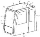
図1、図2に示すように、建設機械のキャブフレーム構造は、一般に、キャブ(運転席)前方の左右に立てて配置されたフロントピラー1と、フロントピラー1の上端から後方に向けて略水平に延出されたルーフピラー2と、ルーフピラー2の後端に接続されてそこから下方に延出されたリヤピラー3と、フロントピラー1の上部に左右のフロントピラー1を架け渡して配設されたフロントヘッダー4と、リヤピラー3の上部に左右のリヤピラー3を架け渡して配設されたリヤヘッダー5とを備えている。
As shown in FIG. 1 and FIG. 2, the cab frame structure of a construction machine generally has a
フロントピラー1及びルーフピラー2には、ガイドレール6が設けられており、このガイドレール6には、前窓ユニット7に装着された被ガイド部材8(一例としてガイドローラ、突起等)が係合されている。前窓ユニット7は、被ガイド部材8がガイドレール6に案内されることで、フロントピラー1及びルーフピラー2に沿って移動し、フロントピラー1に立った状態で支持される閉位置とルーフピラー2に水平状態で支持される開位置とに切り替えられ、キャブの前面を開閉する。フロントヘッダー4は、閉位置にセットされた前窓ユニット7の上端の位置に合わせて配置される。
A
ところで、この種の建設機械のキャブフレーム構造として、フロントピラー1及びルーフピラー2を一本のカーブされた管材9で構成することで、強度を向上させると共に外観上の見栄えを向上させたものが知られている(特許文献1参照)。
By the way, as a cab frame structure of this type of construction machine, it is known that the
フロントピラー1とルーフピラー2とを一本の管材9で構成する場合、図3(a)に示すように、管材9のフロントピラー1とルーフピラー2とを繋ぐ部分に、カーブ部10が形成される。このカーブ部10は、例えば図3(b)に示す断面形状の直線状の管材(異形鋼管)9を曲げ成形することで形成される。管材9を曲げ成形すると、カーブ部10において、カーブ外側10aの曲率半径がカーブ内側10bの曲率半径よりも大きくなる。
When the
カーブ部10においてカーブ外側10aの曲率半径がカーブ内側10bの曲率半径よりも大きいと、図4に示すように、前窓ユニット7の上端7xの上限位置がカーブ外側10aのアール止まり10xの部分で制限されることから、前窓ユニット7の上端7xの位置をアール止まり10xの部分を大幅に越えて高くすることはできない。このため、前窓ユニット7の上端7xの位置に合わせて配置されるフロントヘッダー4の装着位置を高くできず、運転席の運転者のアイポイントを基準とした上方視角(視界仰角)θ1がフロントヘッダー4によって制限されてしまう。
If the curvature radius of the curve outer side 10a is larger than the curvature radius of the curve inner side 10b in the
前窓ユニット7のガラスに、上端がカーブ部10に沿って湾曲された曲面ガラスを用いれば、その前窓ユニット7の上端の位置を、カーブ部10の外側アール10aのアール止まり10xよりも上方に持ってくることができる。従って、フロントヘッダー4の高さを高めることができ、運転者の上方視角θ1が広がる。しかし、前窓ユニット7に曲面ガラスを用いると、運転者の視界に歪みが生じるため正確な作業に支障を来す虞があり、加えて、その前窓ユニット7をガイドレール6に沿ってルーフピラー2に水平支持される開位置に移動させると、前窓ユニット7の曲面ガラスがルーフピラー2に設けた天井板(図1参照)11と干渉してしまう。このため、前窓ユニット7には、平面ガラス7gが用いられている。
If curved glass whose upper end is curved along the
前窓ユニット7に平面ガラス7gを用いると、図4を用いて説明したように、前窓ユニット7の上端7xの上限位置がカーブ部10のカーブ外側10aのアール止まり10xの部分に突き当たる位置に制限される。このため、その前窓ユニット7の上端7xの位置に合わせて配置されるフロントヘッダー4の高さが制限され、そのフロントヘッダー4によって運転者の上方視角θ1が制限されていたのである。
When the flat glass 7g is used for the
以上の事情を考慮して創案された本発明の目的は、フロントピラーとルーフピラーとを一本の管材で構成した建設機械のキャブフレーム構造において、フロントヘッダーの取付位置を可及的に高くでき、運転者の上方視角を広げた建設機械のキャブフレーム構造を提供することにある。 The object of the present invention, which was created in view of the above circumstances, is to make the mounting position of the front header as high as possible in the cab frame structure of a construction machine in which the front pillar and the roof pillar are configured by a single pipe. It is an object of the present invention to provide a cab frame structure for a construction machine that widens the driver's upward viewing angle.
上記目的を達成するために請求項1に係る発明は、建設機械のキャブフレームを構成するフロントピラー及びルーフピラーを、それらフロントピラーとルーフピラーとの接続部にカーブ部を有する一本の管材から構成し、前記管材の前記カーブ部におけるカーブ外側の曲率半径をカーブ内側の曲率半径よりも小さくすることで、前記カーブ部に、前記フロントピラーに支持される前窓ユニットの上端の収容位置を高めるためのスペースを設け、前記カーブ部のカーブ外側に、前記スペースに収容された前記前窓ユニットの上端に位置して、フロントヘッダーを配設し、前記管材が、フロントピラーの部分とルーフピラーの部分とに周方向に余長部を有すると共に、前記カーブ部にカーブ外側に張り出された張出部を有し、長手方向に沿って断面が徐変されたことを特徴とする建設機械のキャブフレーム構造である。
In order to achieve the above-mentioned object, the invention according to
請求項2に係る発明は、前記管材の、前記フロントピラーの部分の周長と、前記ルーフピラーの部分の周長と、前記カーブ部の周長とが等しい請求項1に記載の建設機械のキャブフレーム構造である。
The invention according to
請求項3に係る発明は、前記前窓ユニットが、前記管材に設けられたガイドレールに係合する被ガイド部材を有し、前記管材に沿って移動可能である請求項1又は2に記載の建設機械のキャブフレーム構造である。 According to a third aspect of the present invention, the front window unit has a guided member that engages with a guide rail provided in the pipe material, and is movable along the pipe material . It is a cab frame structure of a construction machine.
請求項4に係る発明は、前記ガイドレールが、前記余長部に形成された請求項3に記載の建設機械のキャブフレーム構造である。
The invention according to
請求項5に係る発明は、前記前窓ユニットが、平面ガラスを有する請求項1から4のいずれか1項に記載の建設機械のキャブフレーム構造である。
The invention according to
請求項6に係る発明は、前記ルーフピラーの部分及び前記フロントピラーの部分は、周方向に一部が180度折り返された折返部を有し、該折返部が前記余長部となる請求項1から5のいずれか1項に記載の建設機械のキャブフレーム構造である。
According to a sixth aspect of the present invention, the roof pillar portion and the front pillar portion each have a folded portion that is folded back 180 degrees in the circumferential direction, and the folded portion serves as the extra length portion. To a cab frame structure for a construction machine according to any one of
本発明に係る建設機械のキャブフレーム構造によれば次のような効果を発揮できる。 According to the cab frame structure of a construction machine according to the present invention, the following effects can be exhibited.
(1)請求項1に係る発明によれば、フロントピラー及びルーフピラーを構成する一本の管材のカーブ部におけるカーブ外側の曲率半径をカーブ内側の曲率半径よりも小さくすることで、カーブ部に前窓ユニットの上端の収容位置を高めるためのスペースを設け、そのスペースに収容された前窓ユニットの上端に位置してフロントヘッダーを配置したので、フロントヘッダーの取付位置を可及的に高めることができ、運転者の上方視角を広げることができる。 (1) According to the first aspect of the present invention, the curvature radius outside the curve in the curved portion of one pipe constituting the front pillar and the roof pillar is made smaller than the curvature radius inside the curve, so that A space is provided to increase the storage position of the upper end of the window unit, and the front header is located at the upper end of the front window unit stored in that space, so that the mounting position of the front header can be increased as much as possible. This can widen the driver's upward viewing angle.
また、管材が、フロントピラーの部分とルーフピラーの部分とに余長部を有すると共にカーブ部にカーブ外側に張り出された張出部を有し、長手方向に沿って断面積が徐変されているので、一本の管材から、カーブ外側の曲率半径がカーブ内側の曲率半径よりも小さいカーブ部を的確に成形できる。 In addition, the pipe material has an extra length portion at the front pillar portion and the roof pillar portion, and has an overhang portion projecting outward from the curve portion, and the cross-sectional area is gradually changed along the longitudinal direction. Therefore, it is possible to accurately form a curved portion having a curvature radius outside the curve smaller than the curvature radius inside the curve from a single pipe.
(2)請求項2に係る発明によれば、フロントピラーの部分の周長とルーフピラーの部分の周長とカーブ部の周長とが等しいので、一本の管材からカーブ部を成形する際に、管材の周方向の伸縮を抑えることができる。
( 2 ) According to the invention of
(3)請求項3に係る発明によれば、前窓ユニットの被ガイド部材が管材に設けられたガイドレールに係合されていて、前窓ユニットを管材に沿って移動させることができるので、キャブの前面を開放できる。よって、運転者は目標物をガラス越しではなく直接目視でき、且つフロントヘッダーの取付位置を可及的に高めることができるので、運転者の上方視角を広げることができる。
( 3 ) According to the invention of
(4)請求項4に係る発明によれば、ガイドレールが余長部に形成されているので、ガイドレールと余長部とを別々に設けた場合と比べ、低コスト化を推進できる。
( 4 ) According to the invention of
(5)請求項5に係る発明によれば、前窓ユニットが平面ガラスを有するので、曲面ガラスのように運転者の視界に歪みが生じることはない。よって、運転者は目標物を歪みなく目視でき、且つフロントヘッダーの取付位置を可及的に高めることができるので、運転者の上方視角を広げることができる。
( 5 ) According to the invention of
本発明の好適実施形態を添付図面に基づいて説明する。 Preferred embodiments of the present invention will be described with reference to the accompanying drawings.
図5に示すように、本実施形態に係る建設機械のキャブフレーム構造は、キャブフレームを構成するフロントピラー1及びルーフピラー2が、それらフロントピラー1とルーフピラー2との接続部にカーブ部10を有する一本の管材9から構成されており、図1、図2を用いて既述したものと同一の構成要素を有する。よって、同一の構成要素には同一の符号を付して説明を省略し、相違点すなわち特徴についてのみ説明する。
As shown in FIG. 5, in the cab frame structure of the construction machine according to the present embodiment, the
本実施形態に係るキャブフレーム構造の特徴は、図5に示すように、管材9のカーブ部10におけるカーブ外側10aの曲率半径をカーブ内側10bの曲率半径よりも小さくすることで、カーブ部10に前窓ユニット7の上端7xの収容位置を高めるためのスペース12を設け、そのスペース12に収容された前窓ユニット7の上端7xの位置に合わせてフロントヘッダー4を配置した点にある。これにより、フロントヘッダー4の取付位置を図4に示す従来例よりも高めることができ、運転者の上方視角θ2を図4に示す従来例の上方視角θ1よりも広げることができる。この点を以下に詳述する。
As shown in FIG. 5, the cab frame structure according to the present embodiment is characterized in that the
先ず、前窓ユニット7のガラスには、既述のように、運転席の運転者の視界の歪みを抑えるため、曲面ガラスではなく平面ガラス7gが用いられている。このため、前窓ユニット7の上端7xの上限位置は、カーブ部10のカーブ外側10aのアール止まり10xの部分に突き当たる高さまでに制限される。この結果、前窓ユニット7の上端7xの位置に合わせて配置されるフロントヘッダー4は、図5に示す本実施形態においても図4に示す従来例においても、カーブ部10のカーブ外側10aにおけるアール止まり10xの部分に配置される。
First, as described above, flat glass 7g is used for the glass of the
ここで、図5に示すようにカーブ部10のカーブ外側10aの曲率半径がカーブ内側10bの曲率半径よりも小さい本実施形態は、図4に示すようにカーブ部10のカーブ外側10aの曲率半径がカーブ内側10bの曲率半径よりも大きい従来例よりも、カーブ外側10aのアール止まり10xの部分の位置が高くなる。このため、アール止まり10xの部分に配置されるフロントヘッダー4の高さは、図5に示す本実施形態の方が図4に示す従来例よりも高くなる。よって、図5に示す本実施形態の運転者の上方視角θ2は、図4に示す従来例の上方視角θ1よりも広がるわけである。
Here, as shown in FIG. 5, the radius of curvature of the curve outer side 10a of the
図6(a)に示すように上述したカーブ部10を有する管材9は、図6(b)に示すようにルーフピラー2の部分に周方向に余長部13を有し、図6(c)に示すようにカーブ部10にカーブ外側に張り出された張出部14を有し、図示はしないがフロントピラー1の部分に図6(b)に示したものと同様の余長部13を有しており、長手方向に沿って断面が徐変されている。かかる構成により、一本の管材9を成形することで、カーブ外側10aの曲率半径がカーブ内側10bの曲率半径よりも小さいカーブ部10を的確に成形できる。
As shown in FIG. 6 (a), the pipe member 9 having the
すなわち、図6(a)に示すカーブ部10を有する管材9は、図6(b)に示すように周方向に段差状の余長部13を有する断面形状の管材(直線状の異形鋼管)を成形(変形)して得ているのであるが、この成形の際、余長部13をカーブ外側10aに張り出させることで、カーブ部10の張出部14としている。具体的には、図6に示す管材9においては、図6(b)に仮想線x内で示す凸周長(余長部13を含む部分)を、図6(c)に仮想線y内で示す部分(張出部14を含む部分)に移動させている。これにより、カーブ外側10aの曲率半径がカーブ内側10bの曲率半径よりも小さいカーブ部10を、的確に成形することができるわけである。
That is, the tubular material 9 having the
図6(a)の仮想線zは、カーブ部10のカーブ外側10aにおいて、カーブ内側10bのアールの同心円を描いたものである。通常、管材を曲げ成形すると、カーブ部10のカーブ外側10aにおいてはこの仮想線zのアールとなり、カーブ外側10aの曲率半径がカーブ内側10bの曲率半径よりも大きくなる。これに対し、本実施形態においては、図6(b)に示すように、周方向に段差状の余長部13を有する断面形状の管材(直線状管材)を成形(変形)し、その際、余長部13をカーブ外側10aに張り出させてカーブ部10の張出部14とすることで、図6(a)に実線で示すように、カーブ部10のカーブ外側10aの曲率半径をカーブ内側10bの曲率半径よりも小さくしている。
An imaginary line z in FIG. 6A depicts a round concentric circle on the curve inner side 10 b on the curve outer side 10 a of the
図6に示す管材9は、フロントピラー1の部分の周長と、ルーフピラー2の部分の周長と、カーブ部10の周長とが等しい。これにより、直線状の管材を成形(変形)してカーブ部10を成形する際に、管材の周方向の伸縮を抑えることができ、カーブ外側10aの曲率半径がカーブ内側10bの曲率半径よりも小さいカーブ部10を、無理なく的確に成形することができる。なお、ここでの「周長が等しい」とは、管材を成形(変形)した際に不可避的に生じる多少の周長差が存在する「周長が略等しい」状態を含む概念である。
In the pipe material 9 shown in FIG. 6, the circumferential length of the
図2に示すように、前窓ユニット7は、管材9に設けられたガイドレール6に係合する被ガイド部材8(一例としてガイドローラ、突起等)を有し、管材9に沿って移動可能となっている。前窓ユニット7は、被ガイド部材8がガイドレール6に案内されることで、フロントピラー1及びルーフピラー2に沿って移動し、フロントピラー1に立った状態で支持される閉位置とルーフピラー2に水平状態で支持される開位置とに切り替えられ、キャブの前面を開閉する。キャブの前面を開放することで、キャブ内の運転者は、目標物をガラス越しではなく直接目視して正確な作業を行うことができ、加えてフロントヘッダー4の取付位置を可及的に高めることができるので、運転者の上方視角θ2を広げることができる。
As shown in FIG. 2, the
ガイドレール6は、図6(b)に示す余長部13に形成されていてもよい。余長部13にガイドレール6を形成する場合について述べる。
The
図6(b)に示すように、管材9のルーフピラー2の部分(フロントピラー1の部分も同様)は、外側曲面部15と、外側曲面部15の下端からキャブ内方に向けて略直角に延出された外側段差部16と、外側段差部16から下方に向けて略直角に延出された外側平坦部17と、外側平坦部17から内方に向けて略直角に延出された下部平坦部18と、下部平坦部18から上方に向けて略直角に延出された内側下部平坦部19と、内側下部平坦部19から内方に向けて斜め上方に延出された内側段差部20と、内側段差部20から上方に向けて延出されて外側曲面部15に繋がる内側上部平坦部21とを有している。外側段差部16と外側平坦部17との部分には、図1に示す側面ドア22の縁部が収容される。
As shown in FIG. 6 (b), the
図6(c)に示すように、管材9のカーブ部10は、張出部14を構成する外側曲面部23と、外側曲面部23の下端からキャブ内方に向けて略直角に延出された外側段差部24と、外側段差部24から下方に向けて略直角に延出された外側平坦部25と、外側平坦部25から内方に向けて略直角に延出された下部平坦部26と、下部平坦部26から上方に向けて略直角に延出されて外側曲面部14に繋がる内側平坦部27とを有している。外側段差部24と外側平坦部25との部分には、図1に示す側面ドア22の縁部が収容される。
As shown in FIG. 6C, the
図6(b)と図6(c)とを対比すれば明らかなように、管材9のルーフピラー2の部分(フロントピラー2の部分も同様)における内側段差部20が、主として余長部13を構成することになる。また、この内側段差部20すなわち余長部13に、ガイドレール6の一部を兼用させることができる。すなわち、図6(b)に示すように、内側下部平坦部19に断面山型の鋼材(頂部が鋭角な山型鋼)28等を取り付けることで、山型鋼28と内側段差部20とによってガイドレール6を構成することができる。
6B and FIG. 6C, it is clear that the inner stepped portion 20 in the
このガイドレール6には、図2に示す前窓ユニット7の被ガイド部材8が係合され、管材9の長手方向に沿って案内される。この場合、山型鋼28と内側段差部20とが傾いていることから、被ガイド部材8にはその傾斜に合ったテーパーローラやテーパー状突起等を用いてもよい。このように、余長部13にガイドレール6の一部を形成してガイドレール6の機能を兼用させることで、余長部13とガイドレール6とを完全に別々に設けた場合と比べ、低コスト化を推進できる。
A guided
図7に、本発明の第1変形実施形態を示す。 FIG. 7 shows a first modified embodiment of the present invention.
この第1変形実施形態に係る建設機械のキャブフレーム構造は、図5及び図6等を用いて既述した前実施形態の建設機械のキャブフレーム構造と基本的な構成は同一であり、図6(b)と図7(b)とを対比すれば明らかなように、図6(b)に示す管材9のルーフピラー2の部分(フロントピラー1の部分も同様)の断面形状のみが前実施形態と異なる。よって、その相違点についてのみ説明し、その他、同一の構成要素については同一の符号を付して説明を省略する。
The cab frame structure of the construction machine according to the first modified embodiment has the same basic configuration as the cab frame structure of the construction machine of the previous embodiment described with reference to FIGS. As is clear from a comparison between FIG. 7B and FIG. 7B, only the cross-sectional shape of the
図7(b)に示すように、この管材9のルーフピラー2の部分(フロントピラー1の部分も同様)は、外側曲面部15と、外側曲面部15の下端からキャブ内方に向けて略直角に延出された外側段差部16と、外側段差部16から下方に向けて略直角に延出された外側平坦部17と、外側平坦部17から内方に向けて略直角に延出された下部平坦部18と、下部平坦部18から上方に向けて略直角に延出された内側下部平坦部29と、内側下部平坦部29から外方に向けて斜め上方に延出された内側下部段差部30と、内側下部段差部30から上方に延出された内側中部平坦部31と、内側中部平坦部31から内方に向けて斜め上方に延出された内側上部段差部32と、内側上部段差部32から上方に延出されて外側曲面部15に繋がる内側上部平坦部33とを有している。
As shown in FIG. 7B, the
図7(b)と図7(c)とを対比すれば明らかなように、この第1変形実施形態においては、内側下部段差部30及び内側上部段差部32が、主として余長部13を構成することになる。また、これら内側下部段差部30及び内側上部段差部32は、ガイドレール6を兼用しており、図2に示す前窓ユニット7の被ガイド部材8が、図7(b)に示す内側下部段差部30と内側上部段差部32との間に収容され、それらに案内されるようになっている。これにより、前窓ユニット7が管材9に沿って移動され、キャブの前面が開閉される。余長部13にガイドレール6が形成されているので、余長部13とガイドレール6とを別々に設けた場合と比べ、低コスト化を推進できる。この第1変形実施形態の基本的な作用効果は、前実施形態と同様なので、説明を省略する。
As is clear from the comparison between FIG. 7B and FIG. 7C, in this first modified embodiment, the inner
図8に、本発明の第2変形実施形態を示す。 FIG. 8 shows a second modified embodiment of the present invention.
この第2変形実施形態に係る建設機械のキャブフレーム構造は、図5及び図6等を用いて既述した最初の実施形態の建設機械のキャブフレーム構造と基本的な構成は同一であり、図6(b)と図8(b)、図6(c)と図8(c)とを対比すれば明らかなように、図6(b)に示す管材9のルーフピラー2の部分(フロントピラー1の部分も同様)の断面形状、図6(c)に示すカーブ部10の断面形状のみが最初の実施形態と異なる。よって、その相違点についてのみ説明し、その他、同一の構成要素については同一の符号を付して説明を省略する。
The cab frame structure of the construction machine according to the second modified embodiment has the same basic configuration as the cab frame structure of the construction machine of the first embodiment described with reference to FIGS. 6 (b) and FIG. 8 (b), and FIG. 6 (c) and FIG. 8 (c) are clearly compared, the portion of the roof pillar 2 (front pillar 1) of the tube material 9 shown in FIG. 6 (b). This also applies to the first embodiment), and only the cross-sectional shape of the
図8(b)に示すように、この管材9のルーフピラー2の部分(フロントピラー1の部分も同様)は、外側曲面部15と、外側曲面部15の下端からキャブ内方に向けて略直角に延出された外側段差部16と、外側段差部16から下方に向けて略直角に延出された外側平坦部17と、外側平坦部17から内方に向けて略直角に延出された下部平坦部18と、下部平坦部18から180度折り返された折返部34と、折返部34から上方に向けて略直角に延出された内側下部平坦部35と、内側下部平坦部35から外方に向けて斜め上方に延出された内側段差部36と、内側段差部36から上方に延出されて外側曲面部15に繋がる内側上部平坦部37とを有している。
As shown in FIG. 8B, the
図8(c)に示すように、管材9のカーブ部10は、張出部14を構成する外側曲面部23と、外側曲面部23の下端からキャブ内方に向けて略直角に延出された外側段差部24と、外側段差部24から下方に向けて略直角に延出された外側平坦部25と、外側平坦部25から内方に向けて略直角に延出された下部平坦部26と、下部平坦部26から上方に向けて略直角に延出された内側下部平坦部38と、内側下部平坦部38から内方に向けて斜め上方に延出された内側段差部39と、内側段差部39から上方に向けて延出されて外側曲面部23に繋がる内側上部平坦部40とを有している。
As shown in FIG. 8C, the
図8(b)と図8(c)とを対比すれば明らかなように、第2変形実施形態においては、管材9のルーフピラー2の部分(フロントピラー1の部分も同様)における折返部34が、主として余長部13を構成することになる。また、この折返部34すなわち余長部13は、ガイドレール6も兼用しており、図8(b)に示す折返部34と内側段差部36との間に前窓ユニット7の被ガイド部材8が収容される。このように、余長部13にガイドレール6を形成することで、余長部13とガイドレール6とを別々に設けた場合と比べ、低コスト化を推進できる。この第2変形実施形態の基本的な作用効果は、最初の実施形態と同様なので、説明を省略する。
As apparent from a comparison between FIG. 8B and FIG. 8C, in the second modified embodiment, the folded portion 34 in the portion of the
上述した各実施形態は、図6(b)、図7(b)又は図8(b)に示す基本断面を有する直線状の管材を成形(変形)することで、基本断面に形成された余長部13をカーブ部10にてカーブ外側10aに張り出させて張出部14としている。これらの実施形態は、図6(b)に示す内側段差部20、図7(b)に示す内側下部段差部30及び内側上部段差部32、図8(b)に示す折返部34のように、基本断面ではガイドレール6として機能する形状を余長部13として利用するタイプの他、基本断面に余分な形状を追加してそれを余長部13とするタイプも考えられる。
In each of the above-described embodiments, the linear tube having the basic cross section shown in FIG. 6 (b), FIG. 7 (b), or FIG. The long portion 13 is projected at the
ところで、図9(a)に示すように、フロントピラー1とカーブ部10とルーフピラー2とを、本発明のように一本の管材から構成するのではなく、夫々別部品とし、図9(b)に示すように、カーブ部10を内側パネル10pと外側パネル10qとをスポット溶接して成る中空体から構成するようにしても、カーブ部10のカーブ外側10aの曲率半径をカーブ内側10bの曲率半径より小さくすることは可能である。
Incidentally, as shown in FIG. 9 (a), the
しかし、この場合、カーブ部10を成す中空体は、スポット溶接部SWのみで接合されたパネル構造となっているので、一体品よりも強度が低い。また、フロントピラー1(管材)とカーブ部10(パネル構造の中空体)とルーフピラー2(管材)とを接続部にて溶接する必要があるため溶接繋ぎ部(溶接部W)の見栄えが悪く、溶接部Wにて強度低下が避けられない。また、溶接歪みが生じるため、精度が安定せず、キャブフレームへの組付性に劣る。加えて、複数の部品を組み立てる組立構造となっているので、組立工数が増加し、コストアップを招く。
However, in this case, since the hollow body forming the
他方、上述した本発明の各実施形態では、一本の管材を成形することでフロントピラー1とカーブ部10とルーフピラー2とを一体的な構成としているので、図9の分割パネルタイプでは必要な溶接部W、スポット溶接部SWが存在せず、強度的に優れたキャブ(キャブフレーム)を提供できる。また、溶接歪みが無いので精度が安定しており、キャブフレームへの組付性がよい。溶接部W、スポット溶接部SWが存在しないので、それらを仕上げるグラインダー加工が不要となる上、外観上の見栄えがよい。キャブフレームの組み立てに関わる工数を低減でき、コストダウンを推進できる。
On the other hand, in each of the above-described embodiments of the present invention, the
本発明は、上述した各実施形態に限定されるものではなく、特許請求の範囲に記載された発明を逸脱しない範囲内であれば、様々な実施形態が含まれる。 The present invention is not limited to the above-described embodiments, and various embodiments are included as long as they do not depart from the invention described in the claims.
1 フロントピラー
2 ルーフピラー
4 フロントヘッダー
6 ガイドレール
7 前窓ユニット
7x 上端
7g 平面ガラス
8 被ガイド部材
9 管材
10 カーブ部
10a カーブ外側
10b カーブ内側
12 スペース
13 余長部
14 張出部
θ2 上方視角
DESCRIPTION OF
Claims (6)
前記管材の前記カーブ部におけるカーブ外側の曲率半径をカーブ内側の曲率半径よりも小さくすることで、前記カーブ部に、前記フロントピラーに支持される前窓ユニットの上端の収容位置を高めるためのスペースを設け、
前記カーブ部のカーブ外側に、前記スペースに収容された前記前窓ユニットの上端に位置して、フロントヘッダーを配設し、
前記管材が、フロントピラーの部分とルーフピラーの部分とに周方向に余長部を有すると共に、前記カーブ部にカーブ外側に張り出された張出部を有し、長手方向に沿って断面が徐変された
ことを特徴とする建設機械のキャブフレーム構造。 The front pillar and the roof pillar constituting the cab frame of the construction machine are constituted by a single pipe member having a curved portion at a connection portion between the front pillar and the roof pillar,
A space for increasing the accommodation position of the upper end of the front window unit supported by the front pillar in the curved portion by making the curvature radius outside the curve portion of the tubular material smaller than the curvature radius inside the curve. Provided,
The front header is disposed outside the curved portion of the curved portion, at the upper end of the front window unit accommodated in the space,
The pipe member has an extra length portion in a circumferential direction at a front pillar portion and a roof pillar portion, and has an overhang portion projecting outward from the curve portion, and the cross section gradually increases along the longitudinal direction. A cab frame structure of a construction machine characterized by being changed .
Priority Applications (5)
| Application Number | Priority Date | Filing Date | Title |
|---|---|---|---|
| JP2010170767A JP5706110B2 (en) | 2010-07-29 | 2010-07-29 | Cab frame structure of construction machinery |
| US13/811,542 US8876196B2 (en) | 2010-07-29 | 2011-07-21 | Cab frame structure for construction machine |
| PCT/JP2011/066589 WO2012014781A1 (en) | 2010-07-29 | 2011-07-21 | Cab frame structure for construction machine |
| CN201180037211.7A CN103140633B (en) | 2010-07-29 | 2011-07-21 | The cab frame structure of building machinery |
| DE112011102533.5T DE112011102533B4 (en) | 2010-07-29 | 2011-07-21 | Cab frame structure for a construction machine |
Applications Claiming Priority (1)
| Application Number | Priority Date | Filing Date | Title |
|---|---|---|---|
| JP2010170767A JP5706110B2 (en) | 2010-07-29 | 2010-07-29 | Cab frame structure of construction machinery |
Publications (3)
| Publication Number | Publication Date |
|---|---|
| JP2012031606A JP2012031606A (en) | 2012-02-16 |
| JP2012031606A5 JP2012031606A5 (en) | 2013-06-27 |
| JP5706110B2 true JP5706110B2 (en) | 2015-04-22 |
Family
ID=45529993
Family Applications (1)
| Application Number | Title | Priority Date | Filing Date |
|---|---|---|---|
| JP2010170767A Active JP5706110B2 (en) | 2010-07-29 | 2010-07-29 | Cab frame structure of construction machinery |
Country Status (5)
| Country | Link |
|---|---|
| US (1) | US8876196B2 (en) |
| JP (1) | JP5706110B2 (en) |
| CN (1) | CN103140633B (en) |
| DE (1) | DE112011102533B4 (en) |
| WO (1) | WO2012014781A1 (en) |
Families Citing this family (4)
| Publication number | Priority date | Publication date | Assignee | Title |
|---|---|---|---|---|
| CA2875553A1 (en) | 2014-12-19 | 2016-06-19 | Metalboss Labs Inc. | Operator cabs and methods for constructing same |
| USD751123S1 (en) | 2014-12-19 | 2016-03-08 | One Fifty Labs Inc. | Operator cab |
| WO2018159860A1 (en) * | 2018-03-26 | 2018-09-07 | 株式会社小松製作所 | Cover for work vehicle, work vehicle cab, and work vehicle |
| CN109482684B (en) * | 2018-11-15 | 2020-07-17 | 陕西宏象房车科技发展有限公司 | Bending forming process of caravan frame |
Family Cites Families (57)
| Publication number | Priority date | Publication date | Assignee | Title |
|---|---|---|---|---|
| US5096253A (en) * | 1990-05-31 | 1992-03-17 | Samsung Heavy Industries, Co., Ltd. | Cabs of heavy construction vehicles with an openable front window and a locking device therefor |
| JPH0612556U (en) * | 1992-07-21 | 1994-02-18 | 株式会社小松製作所 | Cab of construction machinery |
| WO1999032734A1 (en) * | 1997-12-22 | 1999-07-01 | Hitachi Construction Machinery Co., Ltd. | Swinging construction machine, and cab, equipment cover and counter-weight used for the machine |
| DE60001403T2 (en) * | 2000-07-28 | 2003-10-30 | Same Deutz Fahr Spa | Cabin frame for agricultural machine |
| JP4118009B2 (en) * | 2000-09-14 | 2008-07-16 | 株式会社小松製作所 | Construction machine cab front window |
| CN1140676C (en) * | 2000-09-18 | 2004-03-03 | 日立建机株式会社 | Cab for construction machinery |
| AU759661B2 (en) * | 2000-09-18 | 2003-04-17 | Hitachi Construction Machinery Co. Ltd. | Cab for construction machinery |
| JP2002088812A (en) * | 2000-09-18 | 2002-03-27 | Hitachi Constr Mach Co Ltd | Cab for construction machinery |
| DE10118344A1 (en) * | 2001-04-12 | 2002-10-17 | Daimler Chrysler Ag | Modular cab series for trucks |
| US6772544B2 (en) * | 2002-03-28 | 2004-08-10 | Kubota Corporation | Wheeled work vehicle |
| JP2004042739A (en) * | 2002-07-10 | 2004-02-12 | Komatsu Ltd | Driver's cab in work vehicle |
| JP2004090039A (en) * | 2002-08-30 | 2004-03-25 | Komatsu Ltd | Method for bending tubular material having special-shaped cross section for cab frame |
| JP4201126B2 (en) * | 2003-04-10 | 2008-12-24 | 株式会社小松製作所 | Construction machinery cab |
| US7140670B2 (en) * | 2003-08-19 | 2006-11-28 | Custom Products Of Litchfield | Interconnection system for overhead frame structures |
| JP4744296B2 (en) * | 2003-09-09 | 2011-08-10 | 株式会社小松製作所 | Construction machinery cab |
| US7216926B2 (en) * | 2003-10-22 | 2007-05-15 | Hampel Lance T | Vehicle cab |
| JP4209787B2 (en) * | 2004-02-26 | 2009-01-14 | 日立建機株式会社 | Construction machinery |
| JP4484546B2 (en) * | 2004-03-01 | 2010-06-16 | 株式会社小松製作所 | Work machine cab structure |
| KR101059289B1 (en) * | 2004-06-07 | 2011-08-24 | 히다찌 겐끼 가부시키가이샤 | Construction machinery |
| JP4657212B2 (en) * | 2004-07-16 | 2011-03-23 | 株式会社小松製作所 | Construction machinery cab |
| US20060017308A1 (en) * | 2004-07-22 | 2006-01-26 | Kobelco Construction Machinery Co., Ltd. | Driver's cabin of construction machine |
| WO2007010808A1 (en) * | 2005-07-19 | 2007-01-25 | Komatsu Ltd. | Cab structure for construction machine |
| JP4814235B2 (en) * | 2005-07-19 | 2011-11-16 | 株式会社小松製作所 | Construction machinery cab structure |
| JP4804078B2 (en) * | 2005-09-06 | 2011-10-26 | 株式会社小松製作所 | Construction machinery cab structure |
| JP2007099236A (en) * | 2005-10-07 | 2007-04-19 | Shin Caterpillar Mitsubishi Ltd | Cab and working machine |
| JP2007106286A (en) * | 2005-10-14 | 2007-04-26 | Kobelco Contstruction Machinery Ltd | Cab of working machine |
| JP4343900B2 (en) * | 2005-12-26 | 2009-10-14 | 日立建機株式会社 | Construction machinery |
| USD555677S1 (en) * | 2006-03-24 | 2007-11-20 | Kubota Corporation | Cabin for work machine |
| USD549245S1 (en) * | 2006-09-22 | 2007-08-21 | Saf-T-Cab, Inc. | Off highway mobile equipment cab |
| US7959219B2 (en) * | 2006-10-16 | 2011-06-14 | Komatsu Ltd. | Reinforcement structure for pipe and cab structure for construction machine having the same |
| KR101474837B1 (en) * | 2006-11-28 | 2014-12-19 | 히다치 겡키 가부시키 가이샤 | Construction machine |
| USD548753S1 (en) * | 2006-11-29 | 2007-08-14 | Volvo Construction Equipment Holding Sweden Ab | Cabin for heavy construction equipment |
| DE202007006500U1 (en) * | 2007-05-07 | 2008-09-18 | Liebherr-Hydraulikbagger Gmbh | Construction machinery |
| JP4966100B2 (en) * | 2007-05-31 | 2012-07-04 | 日立建機株式会社 | Construction machinery |
| USD571073S1 (en) * | 2007-07-06 | 2008-06-10 | Crown Equipment Corporation | Fork lift truck |
| USD571074S1 (en) * | 2007-07-06 | 2008-06-10 | Crown Equipment Corporation | Overhead guard for a fork lift truck |
| WO2009022510A1 (en) * | 2007-08-13 | 2009-02-19 | Hitachi Construction Machinery Co., Ltd. | Construction machine |
| JP5172381B2 (en) * | 2008-02-22 | 2013-03-27 | 日立建機株式会社 | Construction machinery |
| JP5043188B2 (en) * | 2008-07-16 | 2012-10-10 | 株式会社小松製作所 | Construction machinery cab |
| JP5088268B2 (en) * | 2008-08-11 | 2012-12-05 | コベルコ建機株式会社 | Cab and mobile construction machine equipped with the same |
| USD594480S1 (en) * | 2008-09-30 | 2009-06-16 | Clark Equipment Company | Telehandler cab |
| JP5108709B2 (en) * | 2008-09-30 | 2012-12-26 | 株式会社神戸製鋼所 | Cabin soundproofing equipment for construction machinery |
| DE112009002449B4 (en) * | 2008-10-30 | 2017-06-08 | Komatsu Ltd. | Cabin for construction machine |
| JP4821895B2 (en) * | 2009-07-29 | 2011-11-24 | コベルコ建機株式会社 | Construction machinery |
| JP5234693B2 (en) * | 2009-10-16 | 2013-07-10 | 日立建機株式会社 | Construction machinery |
| JP4976594B2 (en) * | 2009-11-20 | 2012-07-18 | 日立建機株式会社 | Construction machinery |
| KR101764773B1 (en) * | 2010-03-24 | 2017-08-03 | 가부시키가이샤 히다치 겡키 티에라 | Construction machine |
| JP5054802B2 (en) * | 2010-05-24 | 2012-10-24 | 日立建機株式会社 | Construction machinery |
| JP5054805B2 (en) * | 2010-06-09 | 2012-10-24 | 日立建機株式会社 | Construction machinery |
| CN102947512B (en) * | 2010-06-15 | 2015-05-27 | 日立建机株式会社 | Electric construction machine |
| JP5418425B2 (en) * | 2010-07-01 | 2014-02-19 | コベルコ建機株式会社 | Cabin door |
| JP5077411B2 (en) * | 2010-09-14 | 2012-11-21 | コベルコ建機株式会社 | Detachable structure and method for equipment in construction machines |
| JP5356341B2 (en) * | 2010-09-16 | 2013-12-04 | 日立建機株式会社 | Construction machinery |
| JP5516439B2 (en) * | 2011-01-25 | 2014-06-11 | コベルコ建機株式会社 | Construction machinery |
| US8807635B2 (en) * | 2011-02-11 | 2014-08-19 | Cnh Industrial America Llc | Self-cleaning cab floor |
| JP5810683B2 (en) * | 2011-07-04 | 2015-11-11 | コベルコ建機株式会社 | Construction machinery cab support structure |
| US8740288B2 (en) * | 2012-03-30 | 2014-06-03 | Komatsu Ltd. | Cab |
-
2010
- 2010-07-29 JP JP2010170767A patent/JP5706110B2/en active Active
-
2011
- 2011-07-21 DE DE112011102533.5T patent/DE112011102533B4/en active Active
- 2011-07-21 US US13/811,542 patent/US8876196B2/en not_active Expired - Fee Related
- 2011-07-21 CN CN201180037211.7A patent/CN103140633B/en active Active
- 2011-07-21 WO PCT/JP2011/066589 patent/WO2012014781A1/en active Application Filing
Also Published As
| Publication number | Publication date |
|---|---|
| WO2012014781A1 (en) | 2012-02-02 |
| CN103140633B (en) | 2016-01-20 |
| DE112011102533T5 (en) | 2013-05-02 |
| JP2012031606A (en) | 2012-02-16 |
| CN103140633A (en) | 2013-06-05 |
| DE112011102533B4 (en) | 2016-01-21 |
| US8876196B2 (en) | 2014-11-04 |
| US20130119708A1 (en) | 2013-05-16 |
Similar Documents
| Publication | Publication Date | Title |
|---|---|---|
| JP5706110B2 (en) | Cab frame structure of construction machinery | |
| JP6156291B2 (en) | Vehicle door structure | |
| GB2428645A (en) | Fixing arrangement for side spoiler | |
| CN103568787A (en) | Vehicle door frame structure | |
| JP5873106B2 (en) | Design parts arrangement structure for vehicles | |
| JP2014034294A (en) | Column-setting-up sash of door frame | |
| JP2008207670A (en) | Vehicle body front structure | |
| JP5672614B2 (en) | Back door reinforcement structure | |
| JP7062526B2 (en) | Vehicle seat | |
| JP2019084853A (en) | Door sash structure | |
| JP5043091B2 (en) | Vehicle door frame structure | |
| JP6863246B2 (en) | Vehicle rear structure | |
| JP5262979B2 (en) | Vehicle door structure | |
| JP6869278B2 (en) | Vehicle side structure | |
| JP6473436B2 (en) | Body structure | |
| JP2012144176A (en) | Back door structure | |
| JP2007290671A (en) | Fixed door glass supporting structure for vehicle | |
| JP6164919B2 (en) | Assembly structure of instrument panel and A-pillar garnish | |
| JP2020006859A (en) | Peripheral structure for vehicle front pillar | |
| JPWO2009037789A1 (en) | Bumper reinforcement | |
| US11254369B2 (en) | Vehicle body joint structure | |
| JP6406209B2 (en) | Side member structure | |
| JP2018131100A (en) | Vehicle side structure | |
| JP6131236B2 (en) | Vehicle door | |
| JP4742974B2 (en) | Body side structure |
Legal Events
| Date | Code | Title | Description |
|---|---|---|---|
| A521 | Request for written amendment filed |
Free format text: JAPANESE INTERMEDIATE CODE: A523 Effective date: 20130509 |
|
| A621 | Written request for application examination |
Free format text: JAPANESE INTERMEDIATE CODE: A621 Effective date: 20130509 |
|
| A131 | Notification of reasons for refusal |
Free format text: JAPANESE INTERMEDIATE CODE: A131 Effective date: 20140527 |
|
| A521 | Request for written amendment filed |
Free format text: JAPANESE INTERMEDIATE CODE: A523 Effective date: 20140609 |
|
| TRDD | Decision of grant or rejection written | ||
| A01 | Written decision to grant a patent or to grant a registration (utility model) |
Free format text: JAPANESE INTERMEDIATE CODE: A01 Effective date: 20150210 |
|
| A61 | First payment of annual fees (during grant procedure) |
Free format text: JAPANESE INTERMEDIATE CODE: A61 Effective date: 20150226 |
|
| R150 | Certificate of patent or registration of utility model |
Ref document number: 5706110 Country of ref document: JP Free format text: JAPANESE INTERMEDIATE CODE: R150 |
|
| R250 | Receipt of annual fees |
Free format text: JAPANESE INTERMEDIATE CODE: R250 |
|
| R250 | Receipt of annual fees |
Free format text: JAPANESE INTERMEDIATE CODE: R250 |
|
| R250 | Receipt of annual fees |
Free format text: JAPANESE INTERMEDIATE CODE: R250 |
|
| R250 | Receipt of annual fees |
Free format text: JAPANESE INTERMEDIATE CODE: R250 |
|
| R250 | Receipt of annual fees |
Free format text: JAPANESE INTERMEDIATE CODE: R250 |
|
| R250 | Receipt of annual fees |
Free format text: JAPANESE INTERMEDIATE CODE: R250 |
|
| R250 | Receipt of annual fees |
Free format text: JAPANESE INTERMEDIATE CODE: R250 |