EP2564992A1 - Device with electric motor with built-in cooling circuit for controlling tools - Google Patents
Device with electric motor with built-in cooling circuit for controlling tools Download PDFInfo
- Publication number
- EP2564992A1 EP2564992A1 EP12305745A EP12305745A EP2564992A1 EP 2564992 A1 EP2564992 A1 EP 2564992A1 EP 12305745 A EP12305745 A EP 12305745A EP 12305745 A EP12305745 A EP 12305745A EP 2564992 A1 EP2564992 A1 EP 2564992A1
- Authority
- EP
- European Patent Office
- Prior art keywords
- motor
- housing
- electric motor
- tool
- suction pipe
- Prior art date
- Legal status (The legal status is an assumption and is not a legal conclusion. Google has not performed a legal analysis and makes no representation as to the accuracy of the status listed.)
- Granted
Links
Images


Classifications
-
- B—PERFORMING OPERATIONS; TRANSPORTING
- B25—HAND TOOLS; PORTABLE POWER-DRIVEN TOOLS; MANIPULATORS
- B25F—COMBINATION OR MULTI-PURPOSE TOOLS NOT OTHERWISE PROVIDED FOR; DETAILS OR COMPONENTS OF PORTABLE POWER-DRIVEN TOOLS NOT PARTICULARLY RELATED TO THE OPERATIONS PERFORMED AND NOT OTHERWISE PROVIDED FOR
- B25F5/00—Details or components of portable power-driven tools not particularly related to the operations performed and not otherwise provided for
- B25F5/008—Cooling means
Definitions
- the present invention relates to the technical sector of electric motor tools used in construction and construction and more particularly to hand-held sanders.
- hand-held sanders including, with reference to the figure 1 , a gripping arm (1) and carrying on which fits a motor portion (2) in its middle portion, an active head portion (3) at its free end and a gripping handle (4) between the motor part (2) and the active head (3).
- the active head portion has a curved neck shape and receives at its end a grinding wheel (5).
- This type of tooling is usually designated in the professional circles concerned by the pictorial expression "giraffe sander (registered trademark)" because of the particular shape of the active head receiving the articulated sanding pad.
- This type of sander makes it possible to work the ceilings as well as the upper part of the walls, up to a height of about 3 meters.
- These arm sanders also comprise a suction pipe (6) residues resulting from sanding, such as dust, for example, said suction pipe (6) passing through the gripping arm, a first end opening into the active head (3) and the opposite end being connected to a vacuum cleaner (7) to collect the residues.
- the motor part (2) consists of a casing (8) integral with the gripping arm (1) and defining two compartments, a first said upper compartment (9) in which the suction pipe (6) extends. and a second compartment (10) said lower in which is positioned a motor (11), usually a universal electric motor.
- the output shaft of the motor (11) is connected to a planetary gear (12) whose output shaft is connected to a flexible transmission (13).
- the housing (8) comprises at the level of the lower compartment, on either side of the longitudinal sectional plane of the housing (8), a first inlet lug (14a). of cooling air positioned at the engine air intake (11) to direct a flow of air to the manifold of the universal motor (11), between the rotor and the stator thereof, and a second air exhaust port (14b) positioned at the engine exhaust (11), near the planetary gear (12).
- the arm sanders of the prior art thus have the disadvantage of having a bulky engine part.
- the engine may overheat which may lead to permanent deterioration of the latter in case of obstruction of the louvers allowing a circulation of the engine cooling air.
- the working dust can pass inside the engine and cause a short circuit of the rotor or stator of said universal motor.
- the disadvantage of the motor part of the devices of the prior art is to allow the admission of air loaded with abrasive dust or conductive dust that may grill the rotor by short-circuiting the lamellae of the collector or by abrasion of the copper winding of said rotor.
- This portable power sander consists of a motor part (2), an active head (3) and a suction pipe (6) of residues resulting from the sanding, said suction pipe (6) comprising a first end opening into the active head (3) and the opposite end being connected to a vacuum cleaner (7) to collect the residues.
- the motor part (2) consists of a housing (8), which is intended to be handled by the user, in which is positioned a universal motor (11) connected to the electrical network (15), the shaft output motor (11) being connected to a planetary gear (12) whose output shaft is engaged with the active head (3).
- the housing (8) has cooling air intake louvers (14a) positioned at the engine air intake (11) and the gills ( 14b) positioned at the engine exhaust (11), near the planetary gear (12).
- This type of electric motor tool has the same disadvantages as the arm sanders of the prior art.
- This type of tool of the prior art presents the disadvantage of including a universal motor that has a low efficiency, less than 40%, is particularly noisy, the noise generated by the motor being about 90 db, heats a lot with a risk that the cooling is not sufficient, and has a significant pressure drop, has a low life of about 3000 hours, the wear time of the motor brushes,
- One of the aims of the invention is therefore to overcome these drawbacks by proposing in particular a sander arm of simple and inexpensive design, having a motor part of small footprint and preventing any risk of damage to the engine overheating.
- a device of the type comprising at least one motor part comprising a housing in which is positioned an electric motor adapted to drive an active head portion receiving a tool such as a power tool. grinding, sanding or the like, and a suction duct for connection to a vacuum cleaner; said arm sander is remarkable in that the suction pipe opens into the casing of the motor part and in that the motor consists of a so-called sealed high frequency electric motor positioned in the central part of said casing in such a way that air sucked around the motor body.
- the central positioning of the motor in the housing and the absence of independent motor cooling circuit can significantly reduce the size of the motor part.
- such a high-frequency electric motor has the advantage of being particularly quiet, of having no pressure drop, of having a performance greater than 70% and of having a long life, greater than 12000 hours. of use, unlike the electric motors of the devices of the prior art.
- said device according to the invention comprises means for guiding the air sucked around the body of the engine.
- These guide means make it possible to increase the contact time of the air sucked with the body of the motor in order to ensure sufficient cooling of said motor.
- said guide means consist of at least one fin whose longitudinal axis coincides with the longitudinal axis of the motor body.
- said guide means consist of a plurality of longitudinal fins extending perpendicular to the longitudinal axis of the housing from the body of the electric motor to the inner wall of the housing.
- the arm sander according to the invention comprises in the same manner as the sanding machines of the prior art, represented figure 1 , a gripping arm (1) and carrying on which fits a motor portion (2) in its middle portion, an active head portion (3) at its free end and a gripping handle (4) between the motor part (2) and the active head (3).
- the active head portion (3) has a curved neck shape and receives at its end a grinding wheel (5).
- Said sander also comprises a suction pipe (6) residues resulting from sanding, such as dust for example, said suction pipe (6) passing through the gripping arm, a first end opening into the active head (3) and the opposite end being connected to a vacuum cleaner (7) to collect the residues.
- a suction pipe (6) residues resulting from sanding such as dust for example
- the motor part (2) consists of a casing (8) integral with the gripping arm (1) in which the suction pipe (6) extends and a motor (11), usually an electric motor. said at high frequency.
- the output shaft of the motor (11) is connected to a planetary gear (12) whose output shaft is connected to a flexible transmission (13) connected to the active head part (4).
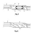
- the suction pipe (6) opens into the casing (8) of the motor part (2) and the motor (11) is positioned in the central part of said casing (8) in such a way that the sucked air circulates around it of the motor body (11).
- the cooling of the motor (11) is ensured by the circulation of the air of the residue suction circuit.
- the motor is cooled as soon as the sander is switched on by the flow of air sucked in at the sander head, avoiding any risk of overheating.
- Said intake air flow for cooling the motor (11) has a much greater flow rate than the air flow necessary to ensure sufficient cooling of said motor (11).
- the central positioning of the engine in the crankcase and the absence of independent circuit of engine cooling can significantly reduce the size of the engine.
- the vacuum cleaner (7) advantageously comprises a known automatic start system so that when the high frequency motor (11) is turned on, the vacuum cleaner (7) is automatically activated and the suction flow cools the engine (11).
- the motor (11) consists of an electric motor said high-frequency sealed, that is to say a motor whose body is airtight in particular.
- the electric motor (11) and the planetary gear (12) may be placed in a sealed enclosure without departing from the scope of the invention.
- the arm sander according to the invention comprises means for guiding the air sucked around and along the motor body (11).
- These guide means consist of a fin (16) whose longitudinal axis coincides with the longitudinal axis of the motor body (11).
- the arm sander according to the invention may comprise one or more concentric fins (16), likewise not or not, without departing from the scope of the invention.
- the fin (16) has a helical shape whose pitch is substantially equal to one third of the length of the housing (8).
- the fin (16) extends from the body of the motor (11) which has a cylindrical shape to the inner wall of the housing (8) which also has a substantially cylindrical shape.
- the housing (8) may have a cross section of any shape such as oblong, polygonal or cylindrical without departing from the scope of the invention.
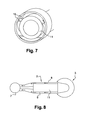
- the casing (8) consists of two substantially semi-cylindrical parts assembled by any appropriate means, such as screws for example, and the helical fin (16) is integral with the inner wall of said casing (8). ), the fin and the housing being obtained in one piece by molding for example.
- said power sander consists of a motor part (2), an active head (3).
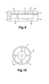
- the motor part (2) consists of a casing (8), which is intended to be handled by the user, in which is positioned a so-called high frequency waterproof motor (11) connected to the automatic starting system a vacuum cleaner (7), the output shaft of the motor (11) being connected to a planetary gear (12) whose output shaft is engaged with the active head (3).
- the motor (11) is positioned in the central part of said housing (8) so that the sucked air circulates around the body of the motor (11), the space formed between the motor and the inner wall of the housing (8) forms a suction pipe (6), a first end of which opens into the active part (3) and whose other end is connected to the vacuum cleaner (7).
- the cooling of the motor (11) is ensured by the circulation of the air of the suction circuit of the residues.
- the housing (8) comprises means (16) for guiding the air sucked around and along the body of the motor (11).
- These guide means (16) consist of a plurality of longitudinal fins extending perpendicular to the longitudinal axis of the housing (8) from the motor body (11) to the inner wall of the housing (8).
- the housing (8) and the motor body (11) have a cylindrical shape, the motor body (11) extending coaxially with the housing (8), and the guide means are consisting of four radial fins uniformly distributed around the motor body (11).
- guide means may include any number of fins without departing from the scope of the invention.
Landscapes
- Engineering & Computer Science (AREA)
- Mechanical Engineering (AREA)
- Finish Polishing, Edge Sharpening, And Grinding By Specific Grinding Devices (AREA)
- Grinding-Machine Dressing And Accessory Apparatuses (AREA)
Abstract
Description
La présente invention concerne le secteur technique des outils à moteur électrique utilisés dans le bâtiment et la construction et concerne plus particulièrement les ponceuses à bras.The present invention relates to the technical sector of electric motor tools used in construction and construction and more particularly to hand-held sanders.
On connaît bien des ponceuses à bras comprenant, en référence à la
Ce type d'outillage est usuellement désigné dans les milieux professionnels concernés par l'expression imagée « ponceuse girafe (marque déposée) » en raison de la forme particulière de la tête active recevant le plateau de ponçage articulé. Ce type de ponceuse permet de travailler les plafonds ainsi que la partie haute des murs, jusqu'à une hauteur d'environ 3 mètres.This type of tooling is usually designated in the professional circles concerned by the pictorial expression "giraffe sander (registered trademark)" because of the particular shape of the active head receiving the articulated sanding pad. This type of sander makes it possible to work the ceilings as well as the upper part of the walls, up to a height of about 3 meters.
Ces ponceuses à bras comportent également une conduite d'aspiration (6) des résidus résultant du ponçage, tels que la poussière par exemple, ladite conduite d'aspiration (6) passant dans le bras de préhension, une première extrémité débouchant dans la tête active (3) et l'extrémité opposée étant connectée à un aspirateur (7) pour recueillir les résidus.These arm sanders also comprise a suction pipe (6) residues resulting from sanding, such as dust, for example, said suction pipe (6) passing through the gripping arm, a first end opening into the active head (3) and the opposite end being connected to a vacuum cleaner (7) to collect the residues.
Selon l'art antérieur, en référence à la
Afin d'assurer le refroidissement du moteur (11), le carter (8) comporte au niveau du compartiment inférieur, de part et d'autre du plan de coupe longitudinal du carter (8), une première ouie (14a) d'admission d'air de refroidissement positionnée au niveau de l'admission d'air du moteur (11) afin de diriger un flux d'air vers le collecteur du moteur universel (11), entre le rotor et le stator de ce dernier, et une seconde ouie (14b) d'échappement d'air positionnée au niveau de l'échappement d'air du moteur (11), à proximité du réducteur planétaire (12).In order to ensure the cooling of the motor (11), the housing (8) comprises at the level of the lower compartment, on either side of the longitudinal sectional plane of the housing (8), a first inlet lug (14a). of cooling air positioned at the engine air intake (11) to direct a flow of air to the manifold of the universal motor (11), between the rotor and the stator thereof, and a second air exhaust port (14b) positioned at the engine exhaust (11), near the planetary gear (12).
Les ponceuses à bras de l'art antérieur présentent ainsi l'inconvénient d'avoir une partie moteur encombrante.The arm sanders of the prior art thus have the disadvantage of having a bulky engine part.
Par ailleurs, le moteur risque une surchauffe pouvant conduire à une détérioration définitive de ce dernier en cas d'obstruction des ouies permettant une circulation de l'air de refroidissement du moteur.In addition, the engine may overheat which may lead to permanent deterioration of the latter in case of obstruction of the louvers allowing a circulation of the engine cooling air.
De plus, les poussières de travail peuvent passer à l'intérieur du moteur et provoquer un court-circuit du rotor ou du stator dudit moteur universel. En effet, l'inconvénient de la partie moteur des dispositifs de l'art antérieur est de permettre l'admission d'air chargé de poussières abrasives ou de poussières conductrices qui risquent de faire griller le rotor soit en court-circuitant les lamelles du collecteur soit par une abrasion du bobinage en cuivre dudit rotor.In addition, the working dust can pass inside the engine and cause a short circuit of the rotor or stator of said universal motor. Indeed, the disadvantage of the motor part of the devices of the prior art is to allow the admission of air loaded with abrasive dust or conductive dust that may grill the rotor by short-circuiting the lamellae of the collector or by abrasion of the copper winding of said rotor.
On connait également des outils portatifs à moteurs électriques, dits outils électroportatifs, tels qu'une ponceuse électroportative, par exemple, représentée schématiquement sur la
Ce type d'outil à moteur électrique présente les mêmes inconvénients que les ponceuses à bras de l'art antérieur. Ce type d'outil de l'art antérieur présente l'inconvénient notamment de comporter un moteur universel qui a un faible rendement, inférieur à 40%, est particulièrement bruyant, le bruit généré par le moteur étant d'environ 90 db, chauffe beaucoup avec un risque que le refroidissement ne soit pas suffisant, et présente une perte de charge importante, présente une longévité faible d'environ 3000 heures, soit la durée d'usure des balais du moteur,This type of electric motor tool has the same disadvantages as the arm sanders of the prior art. This type of tool of the prior art presents the disadvantage of including a universal motor that has a low efficiency, less than 40%, is particularly noisy, the noise generated by the motor being about 90 db, heats a lot with a risk that the cooling is not sufficient, and has a significant pressure drop, has a low life of about 3000 hours, the wear time of the motor brushes,
L'un des buts de l'invention est donc de remédier à ces inconvénients en proposant notamment une ponceuse à bras de conception simple et peu onéreuse, présentant une partie moteur de faible encombrement et empêchant tout risque de détérioration du moteur par surchauffe.One of the aims of the invention is therefore to overcome these drawbacks by proposing in particular a sander arm of simple and inexpensive design, having a motor part of small footprint and preventing any risk of damage to the engine overheating.
A cet effet, et conformément à l'invention, il est proposé un dispositif du type comprenant au moins une partie moteur comportant un carter dans lequel est positionné un moteur électrique apte à entraîner une partie tête active recevant un outil tel qu'un outil de meulage, de ponçage ou similaire, et un conduit d'aspiration destiné à être connecté à un aspirateur ; ladite ponceuse à bras est remarquable en ce que la conduite d'aspiration débouche dans le carter de la partie moteur et en ce que le moteur consiste en un moteur électrique dit à haute fréquence étanche positionné dans la partie centrale dudit carter de telle manière que l'air aspiré circule autour du corps du moteur.For this purpose, and in accordance with the invention, there is provided a device of the type comprising at least one motor part comprising a housing in which is positioned an electric motor adapted to drive an active head portion receiving a tool such as a power tool. grinding, sanding or the like, and a suction duct for connection to a vacuum cleaner; said arm sander is remarkable in that the suction pipe opens into the casing of the motor part and in that the motor consists of a so-called sealed high frequency electric motor positioned in the central part of said casing in such a way that air sucked around the motor body.
On comprend bien que, contrairement aux ponceuses à bras de l'art antérieur dans lesquelles le circuit de refroidissement du moteur est indépendant, le refroidissement du moteur est assuré par la circulation de l'air du circuit d'aspiration des résidus. Ainsi, le refroidissement du moteur est assuré dès la mise en marche de la ponceuse par le flux d'air aspiré au niveau de la tête de la ponceuse, évitant tout risque de surchauffe. Le débit du flux d'air du circuit d'aspiration qui assure le refroidissement du moteur est très largement supérieur au flux d'air nécessaire pour refroidir ledit moteur.It is well understood that, unlike prior art arm sanders in which the engine cooling circuit is independent, the cooling of the engine is ensured by the circulation of the air of the suction circuit residues. Thus, the motor is cooled when the sander is turned on by the air flow sucked in at the sander's head, avoiding any risk of overheating. The flow rate of the air flow of the suction circuit which ensures the cooling of the engine is much greater than the flow of air necessary to cool the engine.
Par ailleurs, le positionnement central du moteur dans le carter et l'absence de circuit indépendant de refroidissement du moteur permettent de réduire considérablement l'encombrement de la partie moteur.Furthermore, the central positioning of the motor in the housing and the absence of independent motor cooling circuit can significantly reduce the size of the motor part.
De plus, un tel moteur électrique à haute fréquence présente l'avantage d'être particulièrement silencieux, de ne pas avoir de perte de charge, d'avoir un rendement supérieur à 70% et d'avoir une grande longévité, supérieure à 12000 heures d'utilisation, contrairement aux moteurs électriques des dispositifs de l'art antérieur.In addition, such a high-frequency electric motor has the advantage of being particularly quiet, of having no pressure drop, of having a performance greater than 70% and of having a long life, greater than 12000 hours. of use, unlike the electric motors of the devices of the prior art.
Selon une caractéristique particulièrement avantageuse, ledit dispositif selon l'invention comporte des moyens de guidage de l'air aspiré autour du corps du moteur. Ces moyens de guidage permettent d'augmenter le temps de contact de l'air aspiré avec le corps du moteur afin d'assurer un refroidissement suffisant dudit moteur.According to a particularly advantageous characteristic, said device according to the invention comprises means for guiding the air sucked around the body of the engine. These guide means make it possible to increase the contact time of the air sucked with the body of the motor in order to ensure sufficient cooling of said motor.
De préférence, lesdits moyens de guidage consistent en au moins une ailette dont l'axe longitudinal est confondu avec l'axe longitudinal du corps du moteur.Preferably, said guide means consist of at least one fin whose longitudinal axis coincides with the longitudinal axis of the motor body.
Selon une variante d'exécution, lesdits moyens de guidage consistent en une pluralité d'ailettes longitudinales s'étendant perpendiculairement à l'axe longitudinal du carter depuis le corps du moteur électrique jusqu'à la paroi intérieure du carter.According to an alternative embodiment, said guide means consist of a plurality of longitudinal fins extending perpendicular to the longitudinal axis of the housing from the body of the electric motor to the inner wall of the housing.
D'autres avantages et caractéristiques ressortiront mieux de la description qui va suivre, d'une unique variante d'exécution, donnée à titre d'exemple non limitatif, de la ponceuse à bras conforme à l'invention, en référence aux dessins annexés sur lesquels :
- La
figure 1 est une vue en perspective d'une ponceuse à bras selon l'art antérieur, - La
figure 2 est une vue en coupe longitudinale schématique de la partie moteur d'une ponceuse à bras selon l'art antérieur, - La
figure 3 est une vue de côté de la partie moteur d'une ponceuse à bras selon l'art antérieur, - La
figure 4 est une vue de dessus schématique d'une ponceuse électroportative selon l'art antérieur, - La
figure 5 est une vue en coupe longitudinale de la partie moteur d'une ponceuse à bras selon l'invention, - La
figure 6 est une vue en coupe longitudinale de la partie moteur dans laquelle le moteur n'est pas représenté afin de visualiser le flux d'aspiration des résidus de la ponceuse à bras selon l'invention, - La
figure 7 est une vue en perspective de la partie moteur coupé suivant un plan de coupe transversale de la ponceuse à bras selon l'invention, - La
figure 8 est une vue de dessus schématique d'une ponceuse électroportative selon l'invention, - La
figure 9 est une vue en coupe longitudinale de la partie moteur de la ponceuse électroportative selon l'invention, - La
figure 10 est une vue en coupe transversale de la partie moteur de la ponceuse électroportative selon l'invention.
- The
figure 1 is a perspective view of a sander with arm according to the prior art, - The
figure 2 is a schematic longitudinal sectional view of the motor part of a sander with arm according to the prior art, - The
figure 3 is a side view of the motor part of a sander with arm according to the prior art, - The
figure 4 is a schematic top view of a power sander according to the prior art, - The
figure 5 is a longitudinal sectional view of the motor part of a sander with arm according to the invention, - The
figure 6 is a longitudinal sectional view of the motor part in which the motor is not shown in order to visualize the suction flow of the residues of the sander according to the invention, - The
figure 7 is a perspective view of the motor part cut along a cross-sectional plane of the arm sander according to the invention, - The
figure 8 is a schematic top view of a portable power sander according to the invention, - The
figure 9 is a longitudinal sectional view of the motor part of the portable power sander according to the invention, - The
figure 10 is a cross-sectional view of the motor part of the portable power sander according to the invention.
Par souci de clarté, dans la suite de la description, les mêmes éléments ont été désignés par les mêmes références aux différentes figures. De plus, les diverses vues en coupe ne sont pas tracées à l'échelle.For the sake of clarity, in the remainder of the description, the same elements have been designated by the same references in the various figures. In addition, the various sectional views are not drawn to scale.
La ponceuse à bras selon l'invention comporte de la même manière que les ponceuses de l'art antérieur, représentée
Ladite ponceuse à bras comporte également une conduite d'aspiration (6) des résidus résultant du ponçage, tels que la poussière par exemple, ladite conduite d'aspiration (6) passant dans le bras de préhension, une première extrémité débouchant dans la tête active (3) et l'extrémité opposée étant connectée à un aspirateur (7) pour recueillir les résidus.Said sander also comprises a suction pipe (6) residues resulting from sanding, such as dust for example, said suction pipe (6) passing through the gripping arm, a first end opening into the active head (3) and the opposite end being connected to a vacuum cleaner (7) to collect the residues.
De plus, la partie moteur (2) est constituée d'un carter (8) solidaire du bras de préhension (1) dans lequel s'étend la conduite d'aspiration (6) et un moteur (11), usuellement un moteur électrique dit à haute fréquence. L'arbre de sortie du moteur (11) est connecté à un réducteur planétaire (12) dont l'arbre de sortie est connecté à une transmission souple (13) connectée à la partie tête active (4).In addition, the motor part (2) consists of a casing (8) integral with the gripping arm (1) in which the suction pipe (6) extends and a motor (11), usually an electric motor. said at high frequency. The output shaft of the motor (11) is connected to a planetary gear (12) whose output shaft is connected to a flexible transmission (13) connected to the active head part (4).
Selon l'invention, en se référant aux
On notera que l'aspirateur (7) comporte avantageusement un système connu de démarrage automatique de sorte que, lorsque le moteur haute fréquence (11) est mis en marche, l'aspirateur (7) est automatiquement actionné et le flux d'aspiration refroidit le moteur (11).Note that the vacuum cleaner (7) advantageously comprises a known automatic start system so that when the high frequency motor (11) is turned on, the vacuum cleaner (7) is automatically activated and the suction flow cools the engine (11).
Le moteur (11) consiste dans un moteur électrique dit à haute fréquence étanche, c'est-à-dire un moteur dont le corps est étanche à l'air notamment. Alternativement, le moteur électrique (11) et le réducteur planétaire (12) pourront être placés dans une enceinte étanche sans sortir du cadre de l'invention.The motor (11) consists of an electric motor said high-frequency sealed, that is to say a motor whose body is airtight in particular. Alternatively, the electric motor (11) and the planetary gear (12) may be placed in a sealed enclosure without departing from the scope of the invention.
On observera qu'un tel moteur électrique présente l'avantage d'être particulièrement silencieux, de ne pas avoir de perte de charge, d'avoir un rendement supérieur à 70% et d'avoir une grande longévité, supérieure à 12000 heures d'utilisation.It will be observed that such an electric motor has the advantage of being particularly quiet, of having no loss of load, of having a yield greater than 70% and of having a long life, greater than 12000 hours of operation. use.
Afin d'augmenter le temps de contact de l'air aspiré avec le corps du moteur et assurer un refroidissement suffisant dudit moteur y compris en cas de faible débit du flux d'aspiration, la ponceuse à bras selon l'invention comporte des moyens de guidage de l'air aspiré autour et le long du corps du moteur (11). Ces moyens de guidage consistent en une ailette (16) dont l'axe longitudinal est confondu avec l'axe longitudinal du corps du moteur (11).In order to increase the contact time of the air sucked with the body of the motor and to ensure sufficient cooling of said motor, including in the case of low flow of the suction flow, the arm sander according to the invention comprises means for guiding the air sucked around and along the motor body (11). These guide means consist of a fin (16) whose longitudinal axis coincides with the longitudinal axis of the motor body (11).
Il va de soi que la ponceuse à bras selon l'invention pourra comprendre une ou plusieurs ailettes (16) concentriques, de même pas ou non, sans sortir du cadre de l'invention.It goes without saying that the arm sander according to the invention may comprise one or more concentric fins (16), likewise not or not, without departing from the scope of the invention.
Dans cet exemple particulier de réalisation, l'ailette (16) présente une forme hélicoïdale dont le pas est sensiblement égal au tiers de la longueur du carter (8).In this particular embodiment, the fin (16) has a helical shape whose pitch is substantially equal to one third of the length of the housing (8).
De préférence, l'ailette (16) s'étend depuis le corps du moteur (11) qui présente une forme cylindrique jusqu'à la paroi intérieure du carter (8) qui présente également une forme sensiblement cylindrique.Preferably, the fin (16) extends from the body of the motor (11) which has a cylindrical shape to the inner wall of the housing (8) which also has a substantially cylindrical shape.
Il va de soi que le carter (8) pourra présenter une section transversale de forme quelconque telle qu'une forme oblongue, polygonale ou cylindrique sans sortir du cadre de l'invention.It goes without saying that the housing (8) may have a cross section of any shape such as oblong, polygonal or cylindrical without departing from the scope of the invention.
Dans cet exemple particulier de réalisation, le carter (8) est constitué de deux parties sensiblement hémicylindriques assemblées par tout moyen approprié, tel que des vis par exemple, et l'ailette hélicoïdale (16) est solidaire de la paroi intérieure dudit carter (8), l'ailette et le carter étant obtenus d'un seul tenant par moulage par exemple.In this particular embodiment, the casing (8) consists of two substantially semi-cylindrical parts assembled by any appropriate means, such as screws for example, and the helical fin (16) is integral with the inner wall of said casing (8). ), the fin and the housing being obtained in one piece by molding for example.
En référence aux
Le moteur (11) est positionné dans la partie centrale dudit carter (8) de telle manière que l'air aspiré circule autour du corps du moteur (11), l'espace formé entre le moteur et la paroi interne du carter (8) forme une conduite d'aspiration (6) dont une première extrémité débouche dans la partie active (3) et dont l'autre extrémité est connectée à l'aspirateur (7). Ainsi, de la même manière que précédemment, le refroidissement du moteur (11) est assuré par la circulation de l'air du circuit d'aspiration des résidus.The motor (11) is positioned in the central part of said housing (8) so that the sucked air circulates around the body of the motor (11), the space formed between the motor and the inner wall of the housing (8) forms a suction pipe (6), a first end of which opens into the active part (3) and whose other end is connected to the vacuum cleaner (7). Thus, in the same manner as above, the cooling of the motor (11) is ensured by the circulation of the air of the suction circuit of the residues.
De préférence, en référence aux
Il va de soi que les moyens de guidage pourront comporter un nombre quelconque d'ailettes sans sortir du cadre de l'invention.It goes without saying that the guide means may include any number of fins without departing from the scope of the invention.
Enfin, il est bien évident que l'invention pourra être appliquée à tout outil à moteur électrique, portatif ou non, et que les exemples que l'on vient de donner ne sont que des illustrations particulières, en aucun cas limitatives quant aux domaines d'application de l'invention.Finally, it is obvious that the invention can be applied to any tool with an electric motor, portable or not, and that the examples that have just been given are only particular illustrations, in no way limiting as to the fields of application of the invention.
Claims (9)
Applications Claiming Priority (1)
| Application Number | Priority Date | Filing Date | Title |
|---|---|---|---|
| FR1157767A FR2979562B1 (en) | 2011-09-02 | 2011-09-02 | ELECTRIC MOTOR DEVICE WITH INTEGRATED COOLING CIRCUIT FOR CONTROLLING TOOLS |
Publications (2)
| Publication Number | Publication Date |
|---|---|
| EP2564992A1 true EP2564992A1 (en) | 2013-03-06 |
| EP2564992B1 EP2564992B1 (en) | 2016-11-02 |
Family
ID=46354119
Family Applications (1)
| Application Number | Title | Priority Date | Filing Date |
|---|---|---|---|
| EP12305745.7A Not-in-force EP2564992B1 (en) | 2011-09-02 | 2012-06-26 | Device with electric motor with built-in cooling circuit for controlling tools |
Country Status (3)
| Country | Link |
|---|---|
| US (1) | US20130059508A1 (en) |
| EP (1) | EP2564992B1 (en) |
| FR (1) | FR2979562B1 (en) |
Families Citing this family (2)
| Publication number | Priority date | Publication date | Assignee | Title |
|---|---|---|---|---|
| FR3021889B1 (en) | 2014-06-05 | 2016-07-01 | Mbh Dev | DEVICE FOR COOLING A CONTROL CIRCUIT OF AN ELECTRIC MOTOR OF AN ELECTROPORTATIVE MACHINE, AND ELECTROPORTATIVE MACHINE EQUIPPED WITH SUCH A POLISHED AIR VACUUM COOLING DEVICE |
| CN110883671A (en) * | 2019-11-27 | 2020-03-17 | 宁夏天地经纬电力设备工程有限公司 | Shell surface polishing equipment for electrical equipment processing |
Citations (4)
| Publication number | Priority date | Publication date | Assignee | Title |
|---|---|---|---|---|
| DE4238564A1 (en) * | 1992-11-14 | 1994-05-19 | Fein C & E | Electric power-driven tool cooled by suction of air through motor - is switched off automatically by disconnection of vacuum hose or insufficiency of vacuum in cooling-air extn. tube |
| EP1081827A1 (en) * | 1999-09-01 | 2001-03-07 | Ramachandran Ramarathnam | A portable electric tool |
| EP1491290A1 (en) * | 2003-06-27 | 2004-12-29 | Festool GmbH | Portable machine tool |
| EP2239091A1 (en) * | 2009-04-03 | 2010-10-13 | M.B.H. Developpement | Electric hand tool with brushless motor device for grinding or drilling |
Family Cites Families (23)
| Publication number | Priority date | Publication date | Assignee | Title |
|---|---|---|---|---|
| US2343875A (en) * | 1941-08-09 | 1944-03-14 | Bell Aircraft Corp | Machine tool |
| US3103069A (en) * | 1962-11-14 | 1963-09-10 | Orthopedic Equipment Co | Vacuumized surgical cast cutter |
| US3371975A (en) * | 1967-02-21 | 1968-03-05 | Henry E. Meltzer | Cooling and carrying box for electric tools and appliances |
| US3383765A (en) * | 1967-03-07 | 1968-05-21 | Henry E. Meltzer | Forced air cooled hair clipper |
| US3481036A (en) * | 1967-09-05 | 1969-12-02 | Lorch Ind Inc | Debris collecting cast cutter |
| US4180946A (en) * | 1975-10-02 | 1980-01-01 | Maurice Brunet | Tool holding spindle assembly particularly for a grinding machine |
| US4281457A (en) * | 1979-10-17 | 1981-08-04 | Black & Decker Inc. | Vacuum-operated cutting tool and system therefor |
| DE3038489C2 (en) * | 1980-10-11 | 1984-01-26 | Festo-Maschinenfabrik Gottlieb Stoll, 7300 Esslingen | Hand machine tool with a rotating tool |
| US4422498A (en) * | 1981-09-08 | 1983-12-27 | Yci Usa, Inc. | Machine tool cooling system |
| US4543718A (en) * | 1984-02-01 | 1985-10-01 | Twin City Surgical, Inc. | Cast cutter apparatus |
| IT1220380B (en) * | 1988-05-24 | 1990-06-15 | Scm Ind Spa | TOOL GROUP FOR WOODWORKING MACHINES |
| US5638575A (en) * | 1995-05-24 | 1997-06-17 | Techtronic Industries Co., Ltd. | Vacuum cleaners |
| DE19839963A1 (en) * | 1998-09-02 | 2000-03-09 | Hilti Ag | Power tool |
| EP1302281B1 (en) * | 2001-10-15 | 2007-05-02 | HILTI Aktiengesellschaft | Cooling air duct in an electric percussive tool |
| DE10242414A1 (en) * | 2002-09-12 | 2004-03-25 | Hilti Ag | Power tool with blower |
| WO2005003580A1 (en) * | 2003-07-04 | 2005-01-13 | Mitsubishi Denki Kabushiki Kaisha | Magnetic bearing device |
| JP4557555B2 (en) * | 2004-01-08 | 2010-10-06 | 株式会社マキタ | Electric tool |
| US7009317B2 (en) * | 2004-01-14 | 2006-03-07 | Caterpillar Inc. | Cooling system for an electric motor |
| CA2568529A1 (en) * | 2004-05-28 | 2005-12-15 | Scientific Molding Corporation Ltd. | Hand-held circular saw, in particular plunge-cut saw |
| US20080086833A1 (en) * | 2004-10-25 | 2008-04-17 | Jacm Limited | Vacuum Cleaner |
| DE102005062693A1 (en) * | 2005-12-28 | 2007-07-05 | Robert Bosch Gmbh | Hand tool machine e.g. triangular sander for use by handyman, has fan wheel provided for producing cooling air flow for cooling motor, where air flow sucked by fan wheel is partially guided over operating unit |
| DE502007001207D1 (en) * | 2007-11-14 | 2009-09-10 | Wessel Werk Gmbh | Elektrosaugkopf |
| US20110248583A1 (en) * | 2008-02-07 | 2011-10-13 | Atlas Dynamic Devices, Llc | Power Transmission Tool And System |
-
2011
- 2011-09-02 FR FR1157767A patent/FR2979562B1/en active Active
-
2012
- 2012-04-05 US US13/440,340 patent/US20130059508A1/en not_active Abandoned
- 2012-06-26 EP EP12305745.7A patent/EP2564992B1/en not_active Not-in-force
Patent Citations (4)
| Publication number | Priority date | Publication date | Assignee | Title |
|---|---|---|---|---|
| DE4238564A1 (en) * | 1992-11-14 | 1994-05-19 | Fein C & E | Electric power-driven tool cooled by suction of air through motor - is switched off automatically by disconnection of vacuum hose or insufficiency of vacuum in cooling-air extn. tube |
| EP1081827A1 (en) * | 1999-09-01 | 2001-03-07 | Ramachandran Ramarathnam | A portable electric tool |
| EP1491290A1 (en) * | 2003-06-27 | 2004-12-29 | Festool GmbH | Portable machine tool |
| EP2239091A1 (en) * | 2009-04-03 | 2010-10-13 | M.B.H. Developpement | Electric hand tool with brushless motor device for grinding or drilling |
Also Published As
| Publication number | Publication date |
|---|---|
| FR2979562A1 (en) | 2013-03-08 |
| US20130059508A1 (en) | 2013-03-07 |
| FR2979562B1 (en) | 2013-09-20 |
| EP2564992B1 (en) | 2016-11-02 |
Similar Documents
| Publication | Publication Date | Title |
|---|---|---|
| EP1404203B1 (en) | Highly efficient autonomous vacuum cleaner | |
| CH650661A5 (en) | HANDPIECE WITH INTEGRATED MOTOR. | |
| EP2667030A1 (en) | Electric compressor housing including a dissipating device, and compressor comprising such a housing | |
| EP2564992B1 (en) | Device with electric motor with built-in cooling circuit for controlling tools | |
| CN108789283B (en) | Torque output tool | |
| FR3043002A1 (en) | ASPIRATOR FOR EMPTYING MATERIAL FROM A PORTABLE TOOL, AND AUTONOMOUS SYSTEM COMPRISING A VACUUM AND A PORTABLE TOOL | |
| FR2917658A1 (en) | ELECTRIC SANDER | |
| FR2834235A1 (en) | WOOD PLANER WITH WOOD CHIP PICKUP MECHANISM | |
| FR2670566A3 (en) | Extractor hood | |
| FR3005883A1 (en) | MATERIAL REMOVAL DEVICE COMPRISING A DEPTH MOTOR TOOL | |
| EP4067236A1 (en) | Method for electric propulsion of an aircraft | |
| FR3028440A3 (en) | ||
| FR3063863A1 (en) | ELECTRONIC HOUSING FOR CONTROLLING AN ENGINE, IN PARTICULAR AN ELECTROPORTATIVE MACHINE | |
| FR2745439A1 (en) | Motor vehicle alternator with improved cooling construction | |
| FR3078480A3 (en) | VACUUM WITH AUXILIARY MOTOR | |
| US11919127B2 (en) | Pole sander | |
| EP3812089A1 (en) | Pole sander | |
| CN219366332U (en) | General portable electric oil-well pump of plug wire charges | |
| CN214519363U (en) | Motorcycle is visor polishing device for accessory | |
| EP2952294A1 (en) | Device for cooling a control circuit of an electric motor of an electric hand power tool, and electric hand power tool provided with such a device for cooling by polluted suction air | |
| EP2247215B1 (en) | Depilatory appliance with optimised air flow | |
| FR2497705A1 (en) | INSTALLATION FOR RECTIFYING BRAKE LININGS BY ROTARY MACHINING | |
| FR2829885A1 (en) | Cooling system for vehicle alternator, includes two fans mounted on either side of rotor contributing to common axial air flow | |
| EP3167193A1 (en) | Electric compressor plate and electric compressor comprising such a plate | |
| CN114505769A (en) | Grinding machine |
Legal Events
| Date | Code | Title | Description |
|---|---|---|---|
| PUAI | Public reference made under article 153(3) epc to a published international application that has entered the european phase |
Free format text: ORIGINAL CODE: 0009012 |
|
| AK | Designated contracting states |
Kind code of ref document: A1 Designated state(s): AL AT BE BG CH CY CZ DE DK EE ES FI FR GB GR HR HU IE IS IT LI LT LU LV MC MK MT NL NO PL PT RO RS SE SI SK SM TR |
|
| AX | Request for extension of the european patent |
Extension state: BA ME |
|
| 17P | Request for examination filed |
Effective date: 20130709 |
|
| RBV | Designated contracting states (corrected) |
Designated state(s): AL AT BE BG CH CY CZ DE DK EE ES FI FR GB GR HR HU IE IS IT LI LT LU LV MC MK MT NL NO PL PT RO RS SE SI SK SM TR |
|
| 17Q | First examination report despatched |
Effective date: 20160309 |
|
| GRAP | Despatch of communication of intention to grant a patent |
Free format text: ORIGINAL CODE: EPIDOSNIGR1 |
|
| INTG | Intention to grant announced |
Effective date: 20160603 |
|
| GRAS | Grant fee paid |
Free format text: ORIGINAL CODE: EPIDOSNIGR3 |
|
| GRAA | (expected) grant |
Free format text: ORIGINAL CODE: 0009210 |
|
| AK | Designated contracting states |
Kind code of ref document: B1 Designated state(s): AL AT BE BG CH CY CZ DE DK EE ES FI FR GB GR HR HU IE IS IT LI LT LU LV MC MK MT NL NO PL PT RO RS SE SI SK SM TR |
|
| REG | Reference to a national code |
Ref country code: GB Ref legal event code: FG4D Free format text: NOT ENGLISH |
|
| REG | Reference to a national code |
Ref country code: AT Ref legal event code: REF Ref document number: 841350 Country of ref document: AT Kind code of ref document: T Effective date: 20161115 Ref country code: CH Ref legal event code: EP |
|
| REG | Reference to a national code |
Ref country code: IE Ref legal event code: FG4D Free format text: LANGUAGE OF EP DOCUMENT: FRENCH |
|
| REG | Reference to a national code |
Ref country code: DE Ref legal event code: R096 Ref document number: 602012024789 Country of ref document: DE |
|
| PG25 | Lapsed in a contracting state [announced via postgrant information from national office to epo] |
Ref country code: LV Free format text: LAPSE BECAUSE OF FAILURE TO SUBMIT A TRANSLATION OF THE DESCRIPTION OR TO PAY THE FEE WITHIN THE PRESCRIBED TIME-LIMIT Effective date: 20161102 |
|
| REG | Reference to a national code |
Ref country code: NL Ref legal event code: MP Effective date: 20161102 |
|
| REG | Reference to a national code |
Ref country code: LT Ref legal event code: MG4D |
|
| REG | Reference to a national code |
Ref country code: AT Ref legal event code: MK05 Ref document number: 841350 Country of ref document: AT Kind code of ref document: T Effective date: 20161102 |
|
| PG25 | Lapsed in a contracting state [announced via postgrant information from national office to epo] |
Ref country code: SE Free format text: LAPSE BECAUSE OF FAILURE TO SUBMIT A TRANSLATION OF THE DESCRIPTION OR TO PAY THE FEE WITHIN THE PRESCRIBED TIME-LIMIT Effective date: 20161102 Ref country code: NO Free format text: LAPSE BECAUSE OF FAILURE TO SUBMIT A TRANSLATION OF THE DESCRIPTION OR TO PAY THE FEE WITHIN THE PRESCRIBED TIME-LIMIT Effective date: 20170202 Ref country code: NL Free format text: LAPSE BECAUSE OF FAILURE TO SUBMIT A TRANSLATION OF THE DESCRIPTION OR TO PAY THE FEE WITHIN THE PRESCRIBED TIME-LIMIT Effective date: 20161102 Ref country code: GR Free format text: LAPSE BECAUSE OF FAILURE TO SUBMIT A TRANSLATION OF THE DESCRIPTION OR TO PAY THE FEE WITHIN THE PRESCRIBED TIME-LIMIT Effective date: 20170203 Ref country code: LT Free format text: LAPSE BECAUSE OF FAILURE TO SUBMIT A TRANSLATION OF THE DESCRIPTION OR TO PAY THE FEE WITHIN THE PRESCRIBED TIME-LIMIT Effective date: 20161102 |
|
| PG25 | Lapsed in a contracting state [announced via postgrant information from national office to epo] |
Ref country code: ES Free format text: LAPSE BECAUSE OF FAILURE TO SUBMIT A TRANSLATION OF THE DESCRIPTION OR TO PAY THE FEE WITHIN THE PRESCRIBED TIME-LIMIT Effective date: 20161102 Ref country code: RS Free format text: LAPSE BECAUSE OF FAILURE TO SUBMIT A TRANSLATION OF THE DESCRIPTION OR TO PAY THE FEE WITHIN THE PRESCRIBED TIME-LIMIT Effective date: 20161102 Ref country code: HR Free format text: LAPSE BECAUSE OF FAILURE TO SUBMIT A TRANSLATION OF THE DESCRIPTION OR TO PAY THE FEE WITHIN THE PRESCRIBED TIME-LIMIT Effective date: 20161102 Ref country code: FI Free format text: LAPSE BECAUSE OF FAILURE TO SUBMIT A TRANSLATION OF THE DESCRIPTION OR TO PAY THE FEE WITHIN THE PRESCRIBED TIME-LIMIT Effective date: 20161102 Ref country code: AT Free format text: LAPSE BECAUSE OF FAILURE TO SUBMIT A TRANSLATION OF THE DESCRIPTION OR TO PAY THE FEE WITHIN THE PRESCRIBED TIME-LIMIT Effective date: 20161102 Ref country code: PL Free format text: LAPSE BECAUSE OF FAILURE TO SUBMIT A TRANSLATION OF THE DESCRIPTION OR TO PAY THE FEE WITHIN THE PRESCRIBED TIME-LIMIT Effective date: 20161102 Ref country code: PT Free format text: LAPSE BECAUSE OF FAILURE TO SUBMIT A TRANSLATION OF THE DESCRIPTION OR TO PAY THE FEE WITHIN THE PRESCRIBED TIME-LIMIT Effective date: 20170302 Ref country code: IS Free format text: LAPSE BECAUSE OF FAILURE TO SUBMIT A TRANSLATION OF THE DESCRIPTION OR TO PAY THE FEE WITHIN THE PRESCRIBED TIME-LIMIT Effective date: 20170302 |
|
| REG | Reference to a national code |
Ref country code: FR Ref legal event code: PLFP Year of fee payment: 6 |
|
| PG25 | Lapsed in a contracting state [announced via postgrant information from national office to epo] |
Ref country code: DK Free format text: LAPSE BECAUSE OF FAILURE TO SUBMIT A TRANSLATION OF THE DESCRIPTION OR TO PAY THE FEE WITHIN THE PRESCRIBED TIME-LIMIT Effective date: 20161102 Ref country code: EE Free format text: LAPSE BECAUSE OF FAILURE TO SUBMIT A TRANSLATION OF THE DESCRIPTION OR TO PAY THE FEE WITHIN THE PRESCRIBED TIME-LIMIT Effective date: 20161102 Ref country code: RO Free format text: LAPSE BECAUSE OF FAILURE TO SUBMIT A TRANSLATION OF THE DESCRIPTION OR TO PAY THE FEE WITHIN THE PRESCRIBED TIME-LIMIT Effective date: 20161102 Ref country code: CZ Free format text: LAPSE BECAUSE OF FAILURE TO SUBMIT A TRANSLATION OF THE DESCRIPTION OR TO PAY THE FEE WITHIN THE PRESCRIBED TIME-LIMIT Effective date: 20161102 Ref country code: SK Free format text: LAPSE BECAUSE OF FAILURE TO SUBMIT A TRANSLATION OF THE DESCRIPTION OR TO PAY THE FEE WITHIN THE PRESCRIBED TIME-LIMIT Effective date: 20161102 |
|
| PGFP | Annual fee paid to national office [announced via postgrant information from national office to epo] |
Ref country code: CH Payment date: 20170619 Year of fee payment: 6 Ref country code: FR Payment date: 20170629 Year of fee payment: 6 Ref country code: GB Payment date: 20170616 Year of fee payment: 6 Ref country code: DE Payment date: 20170614 Year of fee payment: 6 |
|
| REG | Reference to a national code |
Ref country code: DE Ref legal event code: R097 Ref document number: 602012024789 Country of ref document: DE |
|
| PG25 | Lapsed in a contracting state [announced via postgrant information from national office to epo] |
Ref country code: SM Free format text: LAPSE BECAUSE OF FAILURE TO SUBMIT A TRANSLATION OF THE DESCRIPTION OR TO PAY THE FEE WITHIN THE PRESCRIBED TIME-LIMIT Effective date: 20161102 Ref country code: BG Free format text: LAPSE BECAUSE OF FAILURE TO SUBMIT A TRANSLATION OF THE DESCRIPTION OR TO PAY THE FEE WITHIN THE PRESCRIBED TIME-LIMIT Effective date: 20170202 Ref country code: IT Free format text: LAPSE BECAUSE OF FAILURE TO SUBMIT A TRANSLATION OF THE DESCRIPTION OR TO PAY THE FEE WITHIN THE PRESCRIBED TIME-LIMIT Effective date: 20161102 |
|
| PGFP | Annual fee paid to national office [announced via postgrant information from national office to epo] |
Ref country code: BE Payment date: 20170627 Year of fee payment: 6 |
|
| PLBE | No opposition filed within time limit |
Free format text: ORIGINAL CODE: 0009261 |
|
| STAA | Information on the status of an ep patent application or granted ep patent |
Free format text: STATUS: NO OPPOSITION FILED WITHIN TIME LIMIT |
|
| 26N | No opposition filed |
Effective date: 20170803 |
|
| PG25 | Lapsed in a contracting state [announced via postgrant information from national office to epo] |
Ref country code: SI Free format text: LAPSE BECAUSE OF FAILURE TO SUBMIT A TRANSLATION OF THE DESCRIPTION OR TO PAY THE FEE WITHIN THE PRESCRIBED TIME-LIMIT Effective date: 20161102 |
|
| PG25 | Lapsed in a contracting state [announced via postgrant information from national office to epo] |
Ref country code: MC Free format text: LAPSE BECAUSE OF FAILURE TO SUBMIT A TRANSLATION OF THE DESCRIPTION OR TO PAY THE FEE WITHIN THE PRESCRIBED TIME-LIMIT Effective date: 20161102 |
|
| REG | Reference to a national code |
Ref country code: IE Ref legal event code: MM4A |
|
| PG25 | Lapsed in a contracting state [announced via postgrant information from national office to epo] |
Ref country code: LU Free format text: LAPSE BECAUSE OF NON-PAYMENT OF DUE FEES Effective date: 20170626 Ref country code: IE Free format text: LAPSE BECAUSE OF NON-PAYMENT OF DUE FEES Effective date: 20170626 |
|
| PG25 | Lapsed in a contracting state [announced via postgrant information from national office to epo] |
Ref country code: MT Free format text: LAPSE BECAUSE OF FAILURE TO SUBMIT A TRANSLATION OF THE DESCRIPTION OR TO PAY THE FEE WITHIN THE PRESCRIBED TIME-LIMIT Effective date: 20161102 |
|
| REG | Reference to a national code |
Ref country code: DE Ref legal event code: R119 Ref document number: 602012024789 Country of ref document: DE |
|
| REG | Reference to a national code |
Ref country code: CH Ref legal event code: PL |
|
| GBPC | Gb: european patent ceased through non-payment of renewal fee |
Effective date: 20180626 |
|
| REG | Reference to a national code |
Ref country code: BE Ref legal event code: MM Effective date: 20180630 |
|
| PG25 | Lapsed in a contracting state [announced via postgrant information from national office to epo] |
Ref country code: CH Free format text: LAPSE BECAUSE OF NON-PAYMENT OF DUE FEES Effective date: 20180630 Ref country code: DE Free format text: LAPSE BECAUSE OF NON-PAYMENT OF DUE FEES Effective date: 20190101 Ref country code: LI Free format text: LAPSE BECAUSE OF NON-PAYMENT OF DUE FEES Effective date: 20180630 Ref country code: FR Free format text: LAPSE BECAUSE OF NON-PAYMENT OF DUE FEES Effective date: 20180630 Ref country code: GB Free format text: LAPSE BECAUSE OF NON-PAYMENT OF DUE FEES Effective date: 20180626 |
|
| PG25 | Lapsed in a contracting state [announced via postgrant information from national office to epo] |
Ref country code: BE Free format text: LAPSE BECAUSE OF NON-PAYMENT OF DUE FEES Effective date: 20180630 |
|
| PG25 | Lapsed in a contracting state [announced via postgrant information from national office to epo] |
Ref country code: HU Free format text: LAPSE BECAUSE OF FAILURE TO SUBMIT A TRANSLATION OF THE DESCRIPTION OR TO PAY THE FEE WITHIN THE PRESCRIBED TIME-LIMIT; INVALID AB INITIO Effective date: 20120626 |
|
| PG25 | Lapsed in a contracting state [announced via postgrant information from national office to epo] |
Ref country code: CY Free format text: LAPSE BECAUSE OF NON-PAYMENT OF DUE FEES Effective date: 20161102 |
|
| PG25 | Lapsed in a contracting state [announced via postgrant information from national office to epo] |
Ref country code: MK Free format text: LAPSE BECAUSE OF FAILURE TO SUBMIT A TRANSLATION OF THE DESCRIPTION OR TO PAY THE FEE WITHIN THE PRESCRIBED TIME-LIMIT Effective date: 20161102 |
|
| PG25 | Lapsed in a contracting state [announced via postgrant information from national office to epo] |
Ref country code: TR Free format text: LAPSE BECAUSE OF FAILURE TO SUBMIT A TRANSLATION OF THE DESCRIPTION OR TO PAY THE FEE WITHIN THE PRESCRIBED TIME-LIMIT Effective date: 20161102 |
|
| PG25 | Lapsed in a contracting state [announced via postgrant information from national office to epo] |
Ref country code: AL Free format text: LAPSE BECAUSE OF FAILURE TO SUBMIT A TRANSLATION OF THE DESCRIPTION OR TO PAY THE FEE WITHIN THE PRESCRIBED TIME-LIMIT Effective date: 20161102 |