EP2564992A1 - Vorrichtung mit Elektromotor und integriertem Kühlschaltkreis zur Steuerung von Werkzeugen - Google Patents
Vorrichtung mit Elektromotor und integriertem Kühlschaltkreis zur Steuerung von Werkzeugen Download PDFInfo
- Publication number
- EP2564992A1 EP2564992A1 EP12305745A EP12305745A EP2564992A1 EP 2564992 A1 EP2564992 A1 EP 2564992A1 EP 12305745 A EP12305745 A EP 12305745A EP 12305745 A EP12305745 A EP 12305745A EP 2564992 A1 EP2564992 A1 EP 2564992A1
- Authority
- EP
- European Patent Office
- Prior art keywords
- motor
- housing
- electric motor
- tool
- suction pipe
- Prior art date
- Legal status (The legal status is an assumption and is not a legal conclusion. Google has not performed a legal analysis and makes no representation as to the accuracy of the status listed.)
- Granted
Links
- 238000001816 cooling Methods 0.000 title description 18
- 239000000428 dust Substances 0.000 description 5
- 238000013021 overheating Methods 0.000 description 3
- 230000005540 biological transmission Effects 0.000 description 2
- 238000010276 construction Methods 0.000 description 2
- RYGMFSIKBFXOCR-UHFFFAOYSA-N Copper Chemical compound [Cu] RYGMFSIKBFXOCR-UHFFFAOYSA-N 0.000 description 1
- 241000282816 Giraffa camelopardalis Species 0.000 description 1
- 238000005299 abrasion Methods 0.000 description 1
- 229910052802 copper Inorganic materials 0.000 description 1
- 239000010949 copper Substances 0.000 description 1
- 230000006866 deterioration Effects 0.000 description 1
- 230000004907 flux Effects 0.000 description 1
- 210000002816 gill Anatomy 0.000 description 1
- 238000000465 moulding Methods 0.000 description 1
- 238000004804 winding Methods 0.000 description 1
Images


Classifications
-
- B—PERFORMING OPERATIONS; TRANSPORTING
- B25—HAND TOOLS; PORTABLE POWER-DRIVEN TOOLS; MANIPULATORS
- B25F—COMBINATION OR MULTI-PURPOSE TOOLS NOT OTHERWISE PROVIDED FOR; DETAILS OR COMPONENTS OF PORTABLE POWER-DRIVEN TOOLS NOT PARTICULARLY RELATED TO THE OPERATIONS PERFORMED AND NOT OTHERWISE PROVIDED FOR
- B25F5/00—Details or components of portable power-driven tools not particularly related to the operations performed and not otherwise provided for
- B25F5/008—Cooling means
Definitions
- the present invention relates to the technical sector of electric motor tools used in construction and construction and more particularly to hand-held sanders.
- hand-held sanders including, with reference to the figure 1 , a gripping arm (1) and carrying on which fits a motor portion (2) in its middle portion, an active head portion (3) at its free end and a gripping handle (4) between the motor part (2) and the active head (3).
- the active head portion has a curved neck shape and receives at its end a grinding wheel (5).
- This type of tooling is usually designated in the professional circles concerned by the pictorial expression "giraffe sander (registered trademark)" because of the particular shape of the active head receiving the articulated sanding pad.
- This type of sander makes it possible to work the ceilings as well as the upper part of the walls, up to a height of about 3 meters.
- These arm sanders also comprise a suction pipe (6) residues resulting from sanding, such as dust, for example, said suction pipe (6) passing through the gripping arm, a first end opening into the active head (3) and the opposite end being connected to a vacuum cleaner (7) to collect the residues.
- the motor part (2) consists of a casing (8) integral with the gripping arm (1) and defining two compartments, a first said upper compartment (9) in which the suction pipe (6) extends. and a second compartment (10) said lower in which is positioned a motor (11), usually a universal electric motor.
- the output shaft of the motor (11) is connected to a planetary gear (12) whose output shaft is connected to a flexible transmission (13).
- the housing (8) comprises at the level of the lower compartment, on either side of the longitudinal sectional plane of the housing (8), a first inlet lug (14a). of cooling air positioned at the engine air intake (11) to direct a flow of air to the manifold of the universal motor (11), between the rotor and the stator thereof, and a second air exhaust port (14b) positioned at the engine exhaust (11), near the planetary gear (12).
- the arm sanders of the prior art thus have the disadvantage of having a bulky engine part.
- the engine may overheat which may lead to permanent deterioration of the latter in case of obstruction of the louvers allowing a circulation of the engine cooling air.
- the working dust can pass inside the engine and cause a short circuit of the rotor or stator of said universal motor.
- the disadvantage of the motor part of the devices of the prior art is to allow the admission of air loaded with abrasive dust or conductive dust that may grill the rotor by short-circuiting the lamellae of the collector or by abrasion of the copper winding of said rotor.
- This portable power sander consists of a motor part (2), an active head (3) and a suction pipe (6) of residues resulting from the sanding, said suction pipe (6) comprising a first end opening into the active head (3) and the opposite end being connected to a vacuum cleaner (7) to collect the residues.
- the motor part (2) consists of a housing (8), which is intended to be handled by the user, in which is positioned a universal motor (11) connected to the electrical network (15), the shaft output motor (11) being connected to a planetary gear (12) whose output shaft is engaged with the active head (3).
- the housing (8) has cooling air intake louvers (14a) positioned at the engine air intake (11) and the gills ( 14b) positioned at the engine exhaust (11), near the planetary gear (12).
- This type of electric motor tool has the same disadvantages as the arm sanders of the prior art.
- This type of tool of the prior art presents the disadvantage of including a universal motor that has a low efficiency, less than 40%, is particularly noisy, the noise generated by the motor being about 90 db, heats a lot with a risk that the cooling is not sufficient, and has a significant pressure drop, has a low life of about 3000 hours, the wear time of the motor brushes,
- One of the aims of the invention is therefore to overcome these drawbacks by proposing in particular a sander arm of simple and inexpensive design, having a motor part of small footprint and preventing any risk of damage to the engine overheating.
- a device of the type comprising at least one motor part comprising a housing in which is positioned an electric motor adapted to drive an active head portion receiving a tool such as a power tool. grinding, sanding or the like, and a suction duct for connection to a vacuum cleaner; said arm sander is remarkable in that the suction pipe opens into the casing of the motor part and in that the motor consists of a so-called sealed high frequency electric motor positioned in the central part of said casing in such a way that air sucked around the motor body.
- the central positioning of the motor in the housing and the absence of independent motor cooling circuit can significantly reduce the size of the motor part.
- such a high-frequency electric motor has the advantage of being particularly quiet, of having no pressure drop, of having a performance greater than 70% and of having a long life, greater than 12000 hours. of use, unlike the electric motors of the devices of the prior art.
- said device according to the invention comprises means for guiding the air sucked around the body of the engine.
- These guide means make it possible to increase the contact time of the air sucked with the body of the motor in order to ensure sufficient cooling of said motor.
- said guide means consist of at least one fin whose longitudinal axis coincides with the longitudinal axis of the motor body.
- said guide means consist of a plurality of longitudinal fins extending perpendicular to the longitudinal axis of the housing from the body of the electric motor to the inner wall of the housing.
- the arm sander according to the invention comprises in the same manner as the sanding machines of the prior art, represented figure 1 , a gripping arm (1) and carrying on which fits a motor portion (2) in its middle portion, an active head portion (3) at its free end and a gripping handle (4) between the motor part (2) and the active head (3).
- the active head portion (3) has a curved neck shape and receives at its end a grinding wheel (5).
- Said sander also comprises a suction pipe (6) residues resulting from sanding, such as dust for example, said suction pipe (6) passing through the gripping arm, a first end opening into the active head (3) and the opposite end being connected to a vacuum cleaner (7) to collect the residues.
- a suction pipe (6) residues resulting from sanding such as dust for example
- the motor part (2) consists of a casing (8) integral with the gripping arm (1) in which the suction pipe (6) extends and a motor (11), usually an electric motor. said at high frequency.
- the output shaft of the motor (11) is connected to a planetary gear (12) whose output shaft is connected to a flexible transmission (13) connected to the active head part (4).
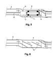
- the suction pipe (6) opens into the casing (8) of the motor part (2) and the motor (11) is positioned in the central part of said casing (8) in such a way that the sucked air circulates around it of the motor body (11).
- the cooling of the motor (11) is ensured by the circulation of the air of the residue suction circuit.
- the motor is cooled as soon as the sander is switched on by the flow of air sucked in at the sander head, avoiding any risk of overheating.
- Said intake air flow for cooling the motor (11) has a much greater flow rate than the air flow necessary to ensure sufficient cooling of said motor (11).
- the central positioning of the engine in the crankcase and the absence of independent circuit of engine cooling can significantly reduce the size of the engine.
- the vacuum cleaner (7) advantageously comprises a known automatic start system so that when the high frequency motor (11) is turned on, the vacuum cleaner (7) is automatically activated and the suction flow cools the engine (11).
- the motor (11) consists of an electric motor said high-frequency sealed, that is to say a motor whose body is airtight in particular.
- the electric motor (11) and the planetary gear (12) may be placed in a sealed enclosure without departing from the scope of the invention.
- the arm sander according to the invention comprises means for guiding the air sucked around and along the motor body (11).
- These guide means consist of a fin (16) whose longitudinal axis coincides with the longitudinal axis of the motor body (11).
- the arm sander according to the invention may comprise one or more concentric fins (16), likewise not or not, without departing from the scope of the invention.
- the fin (16) has a helical shape whose pitch is substantially equal to one third of the length of the housing (8).
- the fin (16) extends from the body of the motor (11) which has a cylindrical shape to the inner wall of the housing (8) which also has a substantially cylindrical shape.
- the housing (8) may have a cross section of any shape such as oblong, polygonal or cylindrical without departing from the scope of the invention.
- the casing (8) consists of two substantially semi-cylindrical parts assembled by any appropriate means, such as screws for example, and the helical fin (16) is integral with the inner wall of said casing (8). ), the fin and the housing being obtained in one piece by molding for example.
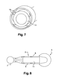
- said power sander consists of a motor part (2), an active head (3).
- the motor part (2) consists of a casing (8), which is intended to be handled by the user, in which is positioned a so-called high frequency waterproof motor (11) connected to the automatic starting system a vacuum cleaner (7), the output shaft of the motor (11) being connected to a planetary gear (12) whose output shaft is engaged with the active head (3).
- the motor (11) is positioned in the central part of said housing (8) so that the sucked air circulates around the body of the motor (11), the space formed between the motor and the inner wall of the housing (8) forms a suction pipe (6), a first end of which opens into the active part (3) and whose other end is connected to the vacuum cleaner (7).
- the cooling of the motor (11) is ensured by the circulation of the air of the suction circuit of the residues.
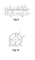
- the housing (8) comprises means (16) for guiding the air sucked around and along the body of the motor (11).
- These guide means (16) consist of a plurality of longitudinal fins extending perpendicular to the longitudinal axis of the housing (8) from the motor body (11) to the inner wall of the housing (8).
- the housing (8) and the motor body (11) have a cylindrical shape, the motor body (11) extending coaxially with the housing (8), and the guide means are consisting of four radial fins uniformly distributed around the motor body (11).
- guide means may include any number of fins without departing from the scope of the invention.
Landscapes
- Engineering & Computer Science (AREA)
- Mechanical Engineering (AREA)
- Finish Polishing, Edge Sharpening, And Grinding By Specific Grinding Devices (AREA)
- Grinding-Machine Dressing And Accessory Apparatuses (AREA)
Applications Claiming Priority (1)
| Application Number | Priority Date | Filing Date | Title |
|---|---|---|---|
| FR1157767A FR2979562B1 (fr) | 2011-09-02 | 2011-09-02 | Dispositif a moteur electrique avec circuit de refroidissement integre pour la commande d'outils |
Publications (2)
| Publication Number | Publication Date |
|---|---|
| EP2564992A1 true EP2564992A1 (de) | 2013-03-06 |
| EP2564992B1 EP2564992B1 (de) | 2016-11-02 |
Family
ID=46354119
Family Applications (1)
| Application Number | Title | Priority Date | Filing Date |
|---|---|---|---|
| EP12305745.7A Not-in-force EP2564992B1 (de) | 2011-09-02 | 2012-06-26 | Vorrichtung mit Elektromotor und integriertem Kühlschaltkreis zur Steuerung von Werkzeugen |
Country Status (3)
| Country | Link |
|---|---|
| US (1) | US20130059508A1 (de) |
| EP (1) | EP2564992B1 (de) |
| FR (1) | FR2979562B1 (de) |
Families Citing this family (2)
| Publication number | Priority date | Publication date | Assignee | Title |
|---|---|---|---|---|
| FR3021889B1 (fr) | 2014-06-05 | 2016-07-01 | Mbh Dev | Dispositif de refroidissement d'un circuit de commande d'un moteur electrique d'une machine electroportative, et machine electroportative equipee d'un tel dispositif de refroidissement par air d'aspiration pollue |
| CN110883671A (zh) * | 2019-11-27 | 2020-03-17 | 宁夏天地经纬电力设备工程有限公司 | 一种电器加工用外壳表面抛光设备 |
Citations (4)
| Publication number | Priority date | Publication date | Assignee | Title |
|---|---|---|---|---|
| DE4238564A1 (de) * | 1992-11-14 | 1994-05-19 | Fein C & E | Elektrowerkzeug mit Absaugung |
| EP1081827A1 (de) * | 1999-09-01 | 2001-03-07 | Ramachandran Ramarathnam | Elektrohandwerkzeug |
| EP1491290A1 (de) * | 2003-06-27 | 2004-12-29 | Festool GmbH | Handwerkzeugmaschine |
| EP2239091A1 (de) * | 2009-04-03 | 2010-10-13 | M.B.H. Developpement | Elektrisches Handwerkzeug mit bürstenlosem Motor zum Schleifen oder Bohren |
Family Cites Families (23)
| Publication number | Priority date | Publication date | Assignee | Title |
|---|---|---|---|---|
| US2343875A (en) * | 1941-08-09 | 1944-03-14 | Bell Aircraft Corp | Machine tool |
| US3103069A (en) * | 1962-11-14 | 1963-09-10 | Orthopedic Equipment Co | Vacuumized surgical cast cutter |
| US3371975A (en) * | 1967-02-21 | 1968-03-05 | Henry E. Meltzer | Cooling and carrying box for electric tools and appliances |
| US3383765A (en) * | 1967-03-07 | 1968-05-21 | Henry E. Meltzer | Forced air cooled hair clipper |
| US3481036A (en) * | 1967-09-05 | 1969-12-02 | Lorch Ind Inc | Debris collecting cast cutter |
| US4180946A (en) * | 1975-10-02 | 1980-01-01 | Maurice Brunet | Tool holding spindle assembly particularly for a grinding machine |
| US4281457A (en) * | 1979-10-17 | 1981-08-04 | Black & Decker Inc. | Vacuum-operated cutting tool and system therefor |
| DE3038489C2 (de) * | 1980-10-11 | 1984-01-26 | Festo-Maschinenfabrik Gottlieb Stoll, 7300 Esslingen | Handwerkzeugmaschine mit einem rotierend angetriebenen Werkzeug |
| US4422498A (en) * | 1981-09-08 | 1983-12-27 | Yci Usa, Inc. | Machine tool cooling system |
| US4543718A (en) * | 1984-02-01 | 1985-10-01 | Twin City Surgical, Inc. | Cast cutter apparatus |
| IT1220380B (it) * | 1988-05-24 | 1990-06-15 | Scm Ind Spa | Gruppo utensile per macchine per la lavorazione del legno |
| US5638575A (en) * | 1995-05-24 | 1997-06-17 | Techtronic Industries Co., Ltd. | Vacuum cleaners |
| DE19839963A1 (de) * | 1998-09-02 | 2000-03-09 | Hilti Ag | Elektrowerkzeug |
| ATE361182T1 (de) * | 2001-10-15 | 2007-05-15 | Hilti Ag | Kühlluftleitung für ein elektrohandwerkzeuggerät mit elektropneumatischem schlagwerk |
| DE10242414A1 (de) * | 2002-09-12 | 2004-03-25 | Hilti Ag | Elektrowerkzeugmaschine mit Gebläse |
| CN100344889C (zh) * | 2003-07-04 | 2007-10-24 | 三菱电机株式会社 | 磁性轴承装置 |
| JP4557555B2 (ja) * | 2004-01-08 | 2010-10-06 | 株式会社マキタ | 電動工具 |
| US7009317B2 (en) * | 2004-01-14 | 2006-03-07 | Caterpillar Inc. | Cooling system for an electric motor |
| EP1768813A2 (de) * | 2004-05-28 | 2007-04-04 | Scientific Molding Corporation Ltd. | Hand-kreissäge, insbesondere tauchsäge |
| US20080086833A1 (en) * | 2004-10-25 | 2008-04-17 | Jacm Limited | Vacuum Cleaner |
| DE102005062693A1 (de) * | 2005-12-28 | 2007-07-05 | Robert Bosch Gmbh | Handwerkzeugmaschine |
| EP2064979B1 (de) * | 2007-11-14 | 2009-07-29 | Wessel-Werk Gmbh | Elektrosaugkopf |
| US20110248583A1 (en) * | 2008-02-07 | 2011-10-13 | Atlas Dynamic Devices, Llc | Power Transmission Tool And System |
-
2011
- 2011-09-02 FR FR1157767A patent/FR2979562B1/fr active Active
-
2012
- 2012-04-05 US US13/440,340 patent/US20130059508A1/en not_active Abandoned
- 2012-06-26 EP EP12305745.7A patent/EP2564992B1/de not_active Not-in-force
Patent Citations (4)
| Publication number | Priority date | Publication date | Assignee | Title |
|---|---|---|---|---|
| DE4238564A1 (de) * | 1992-11-14 | 1994-05-19 | Fein C & E | Elektrowerkzeug mit Absaugung |
| EP1081827A1 (de) * | 1999-09-01 | 2001-03-07 | Ramachandran Ramarathnam | Elektrohandwerkzeug |
| EP1491290A1 (de) * | 2003-06-27 | 2004-12-29 | Festool GmbH | Handwerkzeugmaschine |
| EP2239091A1 (de) * | 2009-04-03 | 2010-10-13 | M.B.H. Developpement | Elektrisches Handwerkzeug mit bürstenlosem Motor zum Schleifen oder Bohren |
Also Published As
| Publication number | Publication date |
|---|---|
| US20130059508A1 (en) | 2013-03-07 |
| FR2979562A1 (fr) | 2013-03-08 |
| FR2979562B1 (fr) | 2013-09-20 |
| EP2564992B1 (de) | 2016-11-02 |
Similar Documents
| Publication | Publication Date | Title |
|---|---|---|
| EP1404203B1 (de) | Selbständiger hochwirksamer staubsauger | |
| CH650661A5 (fr) | Piece a main a moteur integre. | |
| EP3645200A1 (de) | Trennsäge | |
| EP2667030A1 (de) | Gehäuse eines elektrischen Kompressors, das eine Dissipationsvorrichtung umfasst, und Kompressor mit einem solchen Gehäuse | |
| EP2564992B1 (de) | Vorrichtung mit Elektromotor und integriertem Kühlschaltkreis zur Steuerung von Werkzeugen | |
| EP3290157A2 (de) | Winkelschleifer | |
| FR2980392A1 (fr) | Accessoire d'outillage | |
| FR2670566A3 (fr) | Hotte d'aspiration. | |
| FR3043002A1 (fr) | Aspirateur pour aspirer de la matiere en provenance d'un outil portatif, et systeme autonome comprenant un aspirateur et un outil portatif | |
| FR2834235A1 (fr) | Raboteuse a bois avec un mecanisme de ramassage de copeaux de bois | |
| US11919127B2 (en) | Pole sander | |
| EP4523589A1 (de) | Saugkopf mit einem kühlkreislauf für den bürstenmotor | |
| EP4520237A1 (de) | Saugkopf mit durchbrochenem stützring | |
| US20210122004A1 (en) | Pole sander | |
| FR3005883A1 (fr) | Dispositif d'enlevement de matiere comportant un outil a moteur deporte | |
| FR2745439A1 (fr) | Alternateur de vehicule automobile a ventilation interne muni d'un palier perfectionne | |
| FR3028440A3 (de) | ||
| FR3063863A1 (fr) | Boitier electronique pour la commande d'un moteur, notamment d'une machine electroportative | |
| FR3078480A3 (fr) | Aspirateur avec moteur auxiliaire | |
| WO2025181271A1 (fr) | Dispositif de perçage à refroidissement par aspiration | |
| EP2952294A1 (de) | Kühlvorrichtung eines steuerschaltkreises eines elektromotors einer tragbaren elektromaschine, und tragbare elektromaschine, die mit einer solchen kühlvorrichtung durch verwendung von abgesaugter verunreinigter luft ausgestattet ist | |
| FR2829885A1 (fr) | Dispositif de ventilation pour machine electrique tournante et machine electrique pourvue d'un tel dispositif | |
| BE690361A (de) | ||
| FR2471127A1 (fr) | Tondeuse a gazon a lame en forme de faucille | |
| FR3023328A1 (fr) | Plaque d'un compresseur electrique et compresseur electrique comprenant une telle plaque |
Legal Events
| Date | Code | Title | Description |
|---|---|---|---|
| PUAI | Public reference made under article 153(3) epc to a published international application that has entered the european phase |
Free format text: ORIGINAL CODE: 0009012 |
|
| AK | Designated contracting states |
Kind code of ref document: A1 Designated state(s): AL AT BE BG CH CY CZ DE DK EE ES FI FR GB GR HR HU IE IS IT LI LT LU LV MC MK MT NL NO PL PT RO RS SE SI SK SM TR |
|
| AX | Request for extension of the european patent |
Extension state: BA ME |
|
| 17P | Request for examination filed |
Effective date: 20130709 |
|
| RBV | Designated contracting states (corrected) |
Designated state(s): AL AT BE BG CH CY CZ DE DK EE ES FI FR GB GR HR HU IE IS IT LI LT LU LV MC MK MT NL NO PL PT RO RS SE SI SK SM TR |
|
| 17Q | First examination report despatched |
Effective date: 20160309 |
|
| GRAP | Despatch of communication of intention to grant a patent |
Free format text: ORIGINAL CODE: EPIDOSNIGR1 |
|
| INTG | Intention to grant announced |
Effective date: 20160603 |
|
| GRAS | Grant fee paid |
Free format text: ORIGINAL CODE: EPIDOSNIGR3 |
|
| GRAA | (expected) grant |
Free format text: ORIGINAL CODE: 0009210 |
|
| AK | Designated contracting states |
Kind code of ref document: B1 Designated state(s): AL AT BE BG CH CY CZ DE DK EE ES FI FR GB GR HR HU IE IS IT LI LT LU LV MC MK MT NL NO PL PT RO RS SE SI SK SM TR |
|
| REG | Reference to a national code |
Ref country code: GB Ref legal event code: FG4D Free format text: NOT ENGLISH |
|
| REG | Reference to a national code |
Ref country code: AT Ref legal event code: REF Ref document number: 841350 Country of ref document: AT Kind code of ref document: T Effective date: 20161115 Ref country code: CH Ref legal event code: EP |
|
| REG | Reference to a national code |
Ref country code: IE Ref legal event code: FG4D Free format text: LANGUAGE OF EP DOCUMENT: FRENCH |
|
| REG | Reference to a national code |
Ref country code: DE Ref legal event code: R096 Ref document number: 602012024789 Country of ref document: DE |
|
| PG25 | Lapsed in a contracting state [announced via postgrant information from national office to epo] |
Ref country code: LV Free format text: LAPSE BECAUSE OF FAILURE TO SUBMIT A TRANSLATION OF THE DESCRIPTION OR TO PAY THE FEE WITHIN THE PRESCRIBED TIME-LIMIT Effective date: 20161102 |
|
| REG | Reference to a national code |
Ref country code: NL Ref legal event code: MP Effective date: 20161102 |
|
| REG | Reference to a national code |
Ref country code: LT Ref legal event code: MG4D |
|
| REG | Reference to a national code |
Ref country code: AT Ref legal event code: MK05 Ref document number: 841350 Country of ref document: AT Kind code of ref document: T Effective date: 20161102 |
|
| PG25 | Lapsed in a contracting state [announced via postgrant information from national office to epo] |
Ref country code: SE Free format text: LAPSE BECAUSE OF FAILURE TO SUBMIT A TRANSLATION OF THE DESCRIPTION OR TO PAY THE FEE WITHIN THE PRESCRIBED TIME-LIMIT Effective date: 20161102 Ref country code: NO Free format text: LAPSE BECAUSE OF FAILURE TO SUBMIT A TRANSLATION OF THE DESCRIPTION OR TO PAY THE FEE WITHIN THE PRESCRIBED TIME-LIMIT Effective date: 20170202 Ref country code: NL Free format text: LAPSE BECAUSE OF FAILURE TO SUBMIT A TRANSLATION OF THE DESCRIPTION OR TO PAY THE FEE WITHIN THE PRESCRIBED TIME-LIMIT Effective date: 20161102 Ref country code: GR Free format text: LAPSE BECAUSE OF FAILURE TO SUBMIT A TRANSLATION OF THE DESCRIPTION OR TO PAY THE FEE WITHIN THE PRESCRIBED TIME-LIMIT Effective date: 20170203 Ref country code: LT Free format text: LAPSE BECAUSE OF FAILURE TO SUBMIT A TRANSLATION OF THE DESCRIPTION OR TO PAY THE FEE WITHIN THE PRESCRIBED TIME-LIMIT Effective date: 20161102 |
|
| PG25 | Lapsed in a contracting state [announced via postgrant information from national office to epo] |
Ref country code: ES Free format text: LAPSE BECAUSE OF FAILURE TO SUBMIT A TRANSLATION OF THE DESCRIPTION OR TO PAY THE FEE WITHIN THE PRESCRIBED TIME-LIMIT Effective date: 20161102 Ref country code: RS Free format text: LAPSE BECAUSE OF FAILURE TO SUBMIT A TRANSLATION OF THE DESCRIPTION OR TO PAY THE FEE WITHIN THE PRESCRIBED TIME-LIMIT Effective date: 20161102 Ref country code: HR Free format text: LAPSE BECAUSE OF FAILURE TO SUBMIT A TRANSLATION OF THE DESCRIPTION OR TO PAY THE FEE WITHIN THE PRESCRIBED TIME-LIMIT Effective date: 20161102 Ref country code: FI Free format text: LAPSE BECAUSE OF FAILURE TO SUBMIT A TRANSLATION OF THE DESCRIPTION OR TO PAY THE FEE WITHIN THE PRESCRIBED TIME-LIMIT Effective date: 20161102 Ref country code: AT Free format text: LAPSE BECAUSE OF FAILURE TO SUBMIT A TRANSLATION OF THE DESCRIPTION OR TO PAY THE FEE WITHIN THE PRESCRIBED TIME-LIMIT Effective date: 20161102 Ref country code: PL Free format text: LAPSE BECAUSE OF FAILURE TO SUBMIT A TRANSLATION OF THE DESCRIPTION OR TO PAY THE FEE WITHIN THE PRESCRIBED TIME-LIMIT Effective date: 20161102 Ref country code: PT Free format text: LAPSE BECAUSE OF FAILURE TO SUBMIT A TRANSLATION OF THE DESCRIPTION OR TO PAY THE FEE WITHIN THE PRESCRIBED TIME-LIMIT Effective date: 20170302 Ref country code: IS Free format text: LAPSE BECAUSE OF FAILURE TO SUBMIT A TRANSLATION OF THE DESCRIPTION OR TO PAY THE FEE WITHIN THE PRESCRIBED TIME-LIMIT Effective date: 20170302 |
|
| REG | Reference to a national code |
Ref country code: FR Ref legal event code: PLFP Year of fee payment: 6 |
|
| PG25 | Lapsed in a contracting state [announced via postgrant information from national office to epo] |
Ref country code: DK Free format text: LAPSE BECAUSE OF FAILURE TO SUBMIT A TRANSLATION OF THE DESCRIPTION OR TO PAY THE FEE WITHIN THE PRESCRIBED TIME-LIMIT Effective date: 20161102 Ref country code: EE Free format text: LAPSE BECAUSE OF FAILURE TO SUBMIT A TRANSLATION OF THE DESCRIPTION OR TO PAY THE FEE WITHIN THE PRESCRIBED TIME-LIMIT Effective date: 20161102 Ref country code: RO Free format text: LAPSE BECAUSE OF FAILURE TO SUBMIT A TRANSLATION OF THE DESCRIPTION OR TO PAY THE FEE WITHIN THE PRESCRIBED TIME-LIMIT Effective date: 20161102 Ref country code: CZ Free format text: LAPSE BECAUSE OF FAILURE TO SUBMIT A TRANSLATION OF THE DESCRIPTION OR TO PAY THE FEE WITHIN THE PRESCRIBED TIME-LIMIT Effective date: 20161102 Ref country code: SK Free format text: LAPSE BECAUSE OF FAILURE TO SUBMIT A TRANSLATION OF THE DESCRIPTION OR TO PAY THE FEE WITHIN THE PRESCRIBED TIME-LIMIT Effective date: 20161102 |
|
| PGFP | Annual fee paid to national office [announced via postgrant information from national office to epo] |
Ref country code: CH Payment date: 20170619 Year of fee payment: 6 Ref country code: FR Payment date: 20170629 Year of fee payment: 6 Ref country code: GB Payment date: 20170616 Year of fee payment: 6 Ref country code: DE Payment date: 20170614 Year of fee payment: 6 |
|
| REG | Reference to a national code |
Ref country code: DE Ref legal event code: R097 Ref document number: 602012024789 Country of ref document: DE |
|
| PG25 | Lapsed in a contracting state [announced via postgrant information from national office to epo] |
Ref country code: SM Free format text: LAPSE BECAUSE OF FAILURE TO SUBMIT A TRANSLATION OF THE DESCRIPTION OR TO PAY THE FEE WITHIN THE PRESCRIBED TIME-LIMIT Effective date: 20161102 Ref country code: BG Free format text: LAPSE BECAUSE OF FAILURE TO SUBMIT A TRANSLATION OF THE DESCRIPTION OR TO PAY THE FEE WITHIN THE PRESCRIBED TIME-LIMIT Effective date: 20170202 Ref country code: IT Free format text: LAPSE BECAUSE OF FAILURE TO SUBMIT A TRANSLATION OF THE DESCRIPTION OR TO PAY THE FEE WITHIN THE PRESCRIBED TIME-LIMIT Effective date: 20161102 |
|
| PGFP | Annual fee paid to national office [announced via postgrant information from national office to epo] |
Ref country code: BE Payment date: 20170627 Year of fee payment: 6 |
|
| PLBE | No opposition filed within time limit |
Free format text: ORIGINAL CODE: 0009261 |
|
| STAA | Information on the status of an ep patent application or granted ep patent |
Free format text: STATUS: NO OPPOSITION FILED WITHIN TIME LIMIT |
|
| 26N | No opposition filed |
Effective date: 20170803 |
|
| PG25 | Lapsed in a contracting state [announced via postgrant information from national office to epo] |
Ref country code: SI Free format text: LAPSE BECAUSE OF FAILURE TO SUBMIT A TRANSLATION OF THE DESCRIPTION OR TO PAY THE FEE WITHIN THE PRESCRIBED TIME-LIMIT Effective date: 20161102 |
|
| PG25 | Lapsed in a contracting state [announced via postgrant information from national office to epo] |
Ref country code: MC Free format text: LAPSE BECAUSE OF FAILURE TO SUBMIT A TRANSLATION OF THE DESCRIPTION OR TO PAY THE FEE WITHIN THE PRESCRIBED TIME-LIMIT Effective date: 20161102 |
|
| REG | Reference to a national code |
Ref country code: IE Ref legal event code: MM4A |
|
| PG25 | Lapsed in a contracting state [announced via postgrant information from national office to epo] |
Ref country code: LU Free format text: LAPSE BECAUSE OF NON-PAYMENT OF DUE FEES Effective date: 20170626 Ref country code: IE Free format text: LAPSE BECAUSE OF NON-PAYMENT OF DUE FEES Effective date: 20170626 |
|
| PG25 | Lapsed in a contracting state [announced via postgrant information from national office to epo] |
Ref country code: MT Free format text: LAPSE BECAUSE OF FAILURE TO SUBMIT A TRANSLATION OF THE DESCRIPTION OR TO PAY THE FEE WITHIN THE PRESCRIBED TIME-LIMIT Effective date: 20161102 |
|
| REG | Reference to a national code |
Ref country code: DE Ref legal event code: R119 Ref document number: 602012024789 Country of ref document: DE |
|
| REG | Reference to a national code |
Ref country code: CH Ref legal event code: PL |
|
| GBPC | Gb: european patent ceased through non-payment of renewal fee |
Effective date: 20180626 |
|
| REG | Reference to a national code |
Ref country code: BE Ref legal event code: MM Effective date: 20180630 |
|
| PG25 | Lapsed in a contracting state [announced via postgrant information from national office to epo] |
Ref country code: CH Free format text: LAPSE BECAUSE OF NON-PAYMENT OF DUE FEES Effective date: 20180630 Ref country code: DE Free format text: LAPSE BECAUSE OF NON-PAYMENT OF DUE FEES Effective date: 20190101 Ref country code: LI Free format text: LAPSE BECAUSE OF NON-PAYMENT OF DUE FEES Effective date: 20180630 Ref country code: FR Free format text: LAPSE BECAUSE OF NON-PAYMENT OF DUE FEES Effective date: 20180630 Ref country code: GB Free format text: LAPSE BECAUSE OF NON-PAYMENT OF DUE FEES Effective date: 20180626 |
|
| PG25 | Lapsed in a contracting state [announced via postgrant information from national office to epo] |
Ref country code: BE Free format text: LAPSE BECAUSE OF NON-PAYMENT OF DUE FEES Effective date: 20180630 |
|
| PG25 | Lapsed in a contracting state [announced via postgrant information from national office to epo] |
Ref country code: HU Free format text: LAPSE BECAUSE OF FAILURE TO SUBMIT A TRANSLATION OF THE DESCRIPTION OR TO PAY THE FEE WITHIN THE PRESCRIBED TIME-LIMIT; INVALID AB INITIO Effective date: 20120626 |
|
| PG25 | Lapsed in a contracting state [announced via postgrant information from national office to epo] |
Ref country code: CY Free format text: LAPSE BECAUSE OF NON-PAYMENT OF DUE FEES Effective date: 20161102 |
|
| PG25 | Lapsed in a contracting state [announced via postgrant information from national office to epo] |
Ref country code: MK Free format text: LAPSE BECAUSE OF FAILURE TO SUBMIT A TRANSLATION OF THE DESCRIPTION OR TO PAY THE FEE WITHIN THE PRESCRIBED TIME-LIMIT Effective date: 20161102 |
|
| PG25 | Lapsed in a contracting state [announced via postgrant information from national office to epo] |
Ref country code: TR Free format text: LAPSE BECAUSE OF FAILURE TO SUBMIT A TRANSLATION OF THE DESCRIPTION OR TO PAY THE FEE WITHIN THE PRESCRIBED TIME-LIMIT Effective date: 20161102 |
|
| PG25 | Lapsed in a contracting state [announced via postgrant information from national office to epo] |
Ref country code: AL Free format text: LAPSE BECAUSE OF FAILURE TO SUBMIT A TRANSLATION OF THE DESCRIPTION OR TO PAY THE FEE WITHIN THE PRESCRIBED TIME-LIMIT Effective date: 20161102 |