US4281457A - Vacuum-operated cutting tool and system therefor - Google Patents
Vacuum-operated cutting tool and system therefor Download PDFInfo
- Publication number
- US4281457A US4281457A US06/086,025 US8602579A US4281457A US 4281457 A US4281457 A US 4281457A US 8602579 A US8602579 A US 8602579A US 4281457 A US4281457 A US 4281457A
- Authority
- US
- United States
- Prior art keywords
- saw blade
- rotation
- turbine
- housing
- vacuum
- Prior art date
- Legal status (The legal status is an assumption and is not a legal conclusion. Google has not performed a legal analysis and makes no representation as to the accuracy of the status listed.)
- Expired - Lifetime
Links
- 238000005520 cutting process Methods 0.000 title claims abstract description 43
- 230000001939 inductive effect Effects 0.000 claims abstract description 11
- 238000005192 partition Methods 0.000 claims description 11
- 230000000694 effects Effects 0.000 claims description 5
- 238000011144 upstream manufacturing Methods 0.000 claims description 4
- 230000000295 complement effect Effects 0.000 claims description 2
- 230000036346 tooth eruption Effects 0.000 claims 1
- 239000003570 air Substances 0.000 abstract description 11
- 239000011505 plaster Substances 0.000 abstract description 8
- 239000012080 ambient air Substances 0.000 abstract description 5
- 239000012530 fluid Substances 0.000 description 6
- 230000002093 peripheral effect Effects 0.000 description 2
- 239000004568 cement Substances 0.000 description 1
- 238000006243 chemical reaction Methods 0.000 description 1
- 230000003467 diminishing effect Effects 0.000 description 1
- 239000000314 lubricant Substances 0.000 description 1
- 239000000463 material Substances 0.000 description 1
- 230000013011 mating Effects 0.000 description 1
- 230000004048 modification Effects 0.000 description 1
- 238000012986 modification Methods 0.000 description 1
- 230000010355 oscillation Effects 0.000 description 1
- 239000002245 particle Substances 0.000 description 1
- 239000011236 particulate material Substances 0.000 description 1
- 239000013618 particulate matter Substances 0.000 description 1
- 239000000565 sealant Substances 0.000 description 1
Images


Classifications
-
- A—HUMAN NECESSITIES
- A61—MEDICAL OR VETERINARY SCIENCE; HYGIENE
- A61F—FILTERS IMPLANTABLE INTO BLOOD VESSELS; PROSTHESES; DEVICES PROVIDING PATENCY TO, OR PREVENTING COLLAPSING OF, TUBULAR STRUCTURES OF THE BODY, e.g. STENTS; ORTHOPAEDIC, NURSING OR CONTRACEPTIVE DEVICES; FOMENTATION; TREATMENT OR PROTECTION OF EYES OR EARS; BANDAGES, DRESSINGS OR ABSORBENT PADS; FIRST-AID KITS
- A61F15/00—Auxiliary appliances for wound dressings; Dispensing containers for dressings or bandages
- A61F15/02—Devices for cutting bandages of any kind, e.g. shears, cast-cutting saws
-
- B—PERFORMING OPERATIONS; TRANSPORTING
- B23—MACHINE TOOLS; METAL-WORKING NOT OTHERWISE PROVIDED FOR
- B23D—PLANING; SLOTTING; SHEARING; BROACHING; SAWING; FILING; SCRAPING; LIKE OPERATIONS FOR WORKING METAL BY REMOVING MATERIAL, NOT OTHERWISE PROVIDED FOR
- B23D59/00—Accessories specially designed for sawing machines or sawing devices
- B23D59/006—Accessories specially designed for sawing machines or sawing devices for removing or collecting chips
-
- B—PERFORMING OPERATIONS; TRANSPORTING
- B23—MACHINE TOOLS; METAL-WORKING NOT OTHERWISE PROVIDED FOR
- B23Q—DETAILS, COMPONENTS, OR ACCESSORIES FOR MACHINE TOOLS, e.g. ARRANGEMENTS FOR COPYING OR CONTROLLING; MACHINE TOOLS IN GENERAL CHARACTERISED BY THE CONSTRUCTION OF PARTICULAR DETAILS OR COMPONENTS; COMBINATIONS OR ASSOCIATIONS OF METAL-WORKING MACHINES, NOT DIRECTED TO A PARTICULAR RESULT
- B23Q11/00—Accessories fitted to machine tools for keeping tools or parts of the machine in good working condition or for cooling work; Safety devices specially combined with or arranged in, or specially adapted for use in connection with, machine tools
- B23Q11/0042—Devices for removing chips
- B23Q11/0046—Devices for removing chips by sucking
-
- B—PERFORMING OPERATIONS; TRANSPORTING
- B23—MACHINE TOOLS; METAL-WORKING NOT OTHERWISE PROVIDED FOR
- B23Q—DETAILS, COMPONENTS, OR ACCESSORIES FOR MACHINE TOOLS, e.g. ARRANGEMENTS FOR COPYING OR CONTROLLING; MACHINE TOOLS IN GENERAL CHARACTERISED BY THE CONSTRUCTION OF PARTICULAR DETAILS OR COMPONENTS; COMBINATIONS OR ASSOCIATIONS OF METAL-WORKING MACHINES, NOT DIRECTED TO A PARTICULAR RESULT
- B23Q5/00—Driving or feeding mechanisms; Control arrangements therefor
- B23Q5/02—Driving main working members
- B23Q5/04—Driving main working members rotary shafts, e.g. working-spindles
- B23Q5/06—Driving main working members rotary shafts, e.g. working-spindles driven essentially by fluid pressure or pneumatic power
-
- B—PERFORMING OPERATIONS; TRANSPORTING
- B24—GRINDING; POLISHING
- B24B—MACHINES, DEVICES, OR PROCESSES FOR GRINDING OR POLISHING; DRESSING OR CONDITIONING OF ABRADING SURFACES; FEEDING OF GRINDING, POLISHING, OR LAPPING AGENTS
- B24B55/00—Safety devices for grinding or polishing machines; Accessories fitted to grinding or polishing machines for keeping tools or parts of the machine in good working condition
- B24B55/06—Dust extraction equipment on grinding or polishing machines
- B24B55/10—Dust extraction equipment on grinding or polishing machines specially designed for portable grinding machines, e.g. hand-guided
- B24B55/102—Dust extraction equipment on grinding or polishing machines specially designed for portable grinding machines, e.g. hand-guided with rotating tools
-
- B—PERFORMING OPERATIONS; TRANSPORTING
- B27—WORKING OR PRESERVING WOOD OR SIMILAR MATERIAL; NAILING OR STAPLING MACHINES IN GENERAL
- B27B—SAWS FOR WOOD OR SIMILAR MATERIAL; COMPONENTS OR ACCESSORIES THEREFOR
- B27B19/00—Other reciprocating saws with power drive; Fret-saws
- B27B19/006—Other reciprocating saws with power drive; Fret-saws with oscillating saw blades; Hand saws with oscillating saw blades
-
- B—PERFORMING OPERATIONS; TRANSPORTING
- B27—WORKING OR PRESERVING WOOD OR SIMILAR MATERIAL; NAILING OR STAPLING MACHINES IN GENERAL
- B27B—SAWS FOR WOOD OR SIMILAR MATERIAL; COMPONENTS OR ACCESSORIES THEREFOR
- B27B5/00—Sawing machines working with circular or cylindrical saw blades; Components or equipment therefor
- B27B5/29—Details; Component parts; Accessories
- B27B5/30—Details; Component parts; Accessories for mounting or securing saw blades or saw spindles
- B27B5/32—Devices for securing circular saw blades to the saw spindle
-
- B—PERFORMING OPERATIONS; TRANSPORTING
- B28—WORKING CEMENT, CLAY, OR STONE
- B28D—WORKING STONE OR STONE-LIKE MATERIALS
- B28D1/00—Working stone or stone-like materials, e.g. brick, concrete or glass, not provided for elsewhere; Machines, devices, tools therefor
- B28D1/18—Working stone or stone-like materials, e.g. brick, concrete or glass, not provided for elsewhere; Machines, devices, tools therefor by milling, e.g. channelling by means of milling tools
- B28D1/183—Hand tools, e.g. portable, motor driven
-
- F—MECHANICAL ENGINEERING; LIGHTING; HEATING; WEAPONS; BLASTING
- F01—MACHINES OR ENGINES IN GENERAL; ENGINE PLANTS IN GENERAL; STEAM ENGINES
- F01D—NON-POSITIVE DISPLACEMENT MACHINES OR ENGINES, e.g. STEAM TURBINES
- F01D15/00—Adaptations of machines or engines for special use; Combinations of engines with devices driven thereby
- F01D15/06—Adaptations for driving, or combinations with, hand-held tools or the like control thereof
Definitions
- the present invention relates to a power tool adapted to operate in response to a vacuum-induced fluid flow and, more particularly, to a portable vacuum-powered oscillating circular saw suitable for use as a plaster cast cutter.
- Portable power tools adapted for use in cutting and removing plaster casts have generally included an electrically powered motor connected to a circular saw blade through a motion converting mechanism that converts the rotary motion of the motor to an oscillating rotary motion.
- the oscillating nature of the circular blade permits the blade to readily cut through a plaster cast without damage to underlying skin or tissue.
- these tools have also been provided with a hose connection to a vacuum producing source with the inlet end of the hose positioned in or adjacent to the cutting zone of the blade to entrain and remove the debris generated during the cutting operation.
- the electric motor adds weight to the tool and the combined hose and electrical connections limit the maneuverability of the tool. Also, the electric motor generally produces heat energy during use which must be dissipated, and the motor must also be protected or otherwise shielded against the debris generated during a cutting operation.
- a vacuum-operated power tool in accordance with the present invention includes a tool housing having an impeller section that includes a inlet side for drawing ambient air into the tool housing and an outlet side for exhausting the ambient air to a vacuum-inducing source.
- a rotatably mounted turbine means is located within the impeller section and is adapted to rotate in response to the vacuum-induced fluid flow through the impeller section from the inlet side to the outlet side of the tool.
- the turbine means is coupled through a motion converting mechanism to a drive shaft that is adapted to releasably retain a cutting tool, such as a circular saw.
- the motion converting means converts the rotary output motion of the turbine means into a rotary oscillating motion to enable the saw blade to be adapted for cutting plaster casts.
- the motion converting mechanism includes a rotatably mounted shaft connected to the turbine means.
- the shaft includes an eccentric cam portion that fits between the spaced apart tines of a bifurcated wishbone-type cam follower that is connected to the drive shaft.
- a vacuum-operated power tool in accordance with the present invention advantageously provides a lightweight, easily manipulatable tool in which both the power to operate the cutting tool and the air flow to remove the debris generated during the cutting operation are provided by the same vacuum-inducing source.
- FIG. 1 is a perspective view of a portable vacuum-operated power cutting tool in accordance with the present invention
- FIG. 2 is a side elevational view, in cross section, of the vacuum-operated power tool shown in FIG. 1;
- FIG. 2A is an enlarged detail view of a connection joint enclosed by the line 2A in FIG. 2;
- FIG. 2B is an enlarged detail view of a portion of the turbine wheel adjacent a partition wall enclosed by the line 2B in FIG. 2;
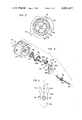
- FIG. 3 is a cross-sectional view of a turbine wheel and a fluid-flow directing nozzle of the power tool illustrated in FIGS. 1 and 2 taken along line 3--3 of FIG. 2;
- FIG. 4 is an exploded perspective view of an exemplary drive train for the power tool illustrated in FIGS. 1 and 2 with selected parts omitted for reasons of clarity;
- FIG. 5 is a detail view of a cam follower portion of the drive train shown in FIG. 4;
- FIG. 6 is a end elevational view of an exemplary circular saw blade for use with the power tool illustrated in FIGS. 1 and 2;
- FIG. 7 is an enlarged detailed view of the circular saw blade of FIG. 6 illustrating the amplitude of the oscillating motion of the blade;
- FIG. 8 is an exploded perspective view of a chuck suitable for use with the power tool of FIGS. 1 and 2 for releasably retaining the circular saw blade of FIG. 6;
- FIG. 9 is a side elevational view, in cross section, of the chuck of FIG. 8 in its assembled state.
- a vacuum-operated power tool in accordance with the present invention suitable for use as a plaster cast cutting tool or the like is generally referred to in the figures by reference character 10.
- the tool 10 includes a housing 12 that includes an inlet section 12A, an impeller section 12B, and an outlet section 12C.
- the inlet section 12A includes a cylindrically extending surface 14 designed for convenient manual gripping and a conical transistion portion 16 that rigidly joins the inlet section 12A with the impeller section 12B.
- a shroud 18 is removably connected to the open, remote end of the inlet section 12A and is designed to partially encircle or enclose a circular saw blade 20 and assist in directing inlet air into the open end of the inlet housing 12A across the cutting zone of the blade 20 as described in more detail below.
- the outlet section 12C includes a cylindrical hose receiving fitting 22 that permits the tool 10 to be connected through a vacuum hose 24 to a vacuum-inducing source such as a vacuum cleaner schematically represented at 26 in FIG. 2.
- the outlet section 12C of the tool 10 is rotatably mounted to the impeller section 12B such that the outlet section can rotate relative to the inlet section as indicated by the double arrow 28 in FIG. 1.
- vacuum hose 24 is also rotatably mounted relative to the hose receiving fitting 22 as indicated by the double arrow 30 such that the tool 10 may be conveniently manipulated with the outlet section 12C and the vacuum hose 24 conforming to each new attitude and position of the tool 10.
- a movable seal structure as shown in FIG. 2A and generally referred to therein by the reference character 32, is used to effect the rotatable connection between the outlet section 12C and the impeller section 12B.
- the outlet section 12C includes a radially inward projecting rim 34 having a curved inner surface that is received by and mates with a peripheral, complementary groove 36 formed in the impeller section 12B.
- a combined sealant/lubricant may be provided on the mating surfaces of the seal 32 to permit low-friction relative rotation and prevent air flow through the seal.
- a vacuum-responsive drive system (FIGS. 2-8) is provided internally of the tool housing 12 and is designed to provide motive power for the circular saw blade 20 to cause the blade to oscillate.
- the drive system includes an impeller or turbine wheel 38, a motion conversion mechanism, generally referred to by the reference character 40, a drive shaft 42, and a chuck assembly 44 (FIGS. 8 and 9) for attaching the saw blade 20 to the drive shaft 42.
- the turbine wheel 38 includes a plurality of equally spaced blades 46 that define intermediate "buckets" or pockets 48 that extend the full width of the wheel 38.
- the turbine wheel 38 is secured to a shaft 50 that is rotatably mounted for rotation about a shaft axis 52.
- the shaft 50 includes a shank portion 50A to which the turbine wheel 38 is secured, an enlarged head portion 50B, and an eccentrically located, axially extending stub shaft 54 that carries a ball bearing 55.
- the shaft 50 is rotatably mounted in a ball bearing 56 that supports the shank portion 50A of the shaft and a needle bearing 58 that supports the enlarged head portion 50B.
- the bearings 56 and 58 are carried in a cylindrical bearing cartridge 60 (FIG. 2) which, in turn, is fitted in an appropriately sized bore formed in a partition 62 that separates the impeller section 12B into an upstream side and a downstream side.
- the partition 62 is counter-bored or recessed on its down-stream side at 64 to accept the right-hand side of the turbine wheel 38.
- an air-flow directing nozzle 66 is secured to the downstream side of the partition 62 and directs a air-flow from an opening 68 formed in the partition from the upstream side to the turbine wheel 38 to cause the turbine wheel to rotate in the direction of the arrow 70 as described more fully below.
- the motion converting mechanism 40 includes a bifurcated "wishbone”shaped cam follower 72 that includes an upper bifurcated portion 72A having spaced apart tines 74 and a lower counterbalancing portion 72B.
- the cam follower 72 includes a mounting hole 76 formed intermediate its ends through which the inner end of the drive shaft 42 is inserted.
- the cam follower 72 is secured to the drive shaft 42 by suitable securing means including the pin 78 as shown in FIG. 4 with the bearing 55 positioned between the tines 74.
- the drive shaft 42 extends through a drive tube 80 (FIG. 2) formed in the inlet section 12A of the housing 12 and is rotatably carried therein in drive shaft bearings 82 for rotation about its axis 84.
- a saw blade 20 suitable for use with the present invention is shown in FIG. 7 and includes a centrally located hexagonal mounting hole 86 and a plurality of equi-spaced peripheral teeth 88.
- the chuck 44 for releasably securing the saw blade 20 to the tool 10 is shown in detail in FIGS. 8 and 9.
- the chuck 44 is mounted on the outer or remote threaded end of the drive shaft 42 and includes a hollow mandrel 90 and a threaded retaining nut 92.
- the mandrel 90 includes a hex-shaped nose 96 with the individual flats or sides 98 of the nose tapered in a forward direction at a selected angle e.g., 5° as indicated by the reference letter A in FIG. 9.
- the mandrel 90 is fitted over the threaded end of the drive shaft 42 and secured in place with a conventional securing means such as a thread locking cement.
- the retainer nut 92 which is preferably fabricated from a plastic material, includes a threaded insert 100 that is press-fitted into an appropriately shaped counter-bore 102 (FIG. 8) formed in the retainer nut 92.
- a peripherally extending, axially directed skirt 104 (FIG. 9) is provided on the side of the retainer nut 92 that faces the mandrel 90 to assist in securing a saw blade 20 to the tool 10.
- the saw blade 20 is mounted on the tool 10 by removing the shroud 18 and then placing the saw blade 20 over the mandrel 90 such that the hex-shaped mounting hole 86 of the saw blade is aligned with the hex-shaped nose 96 of the mandrel 90.
- the saw blade 20 positions itself on the mandrel 90 at a point in which a line-to-line fit (that is, a no clearance fit) exists between the saw blade and the mandrel.
- the retainer nut 92 is threaded onto the remote or distal end of the drive shaft 42 until the skirt 104 contacts the saw blade to secure it in place.
- the remote end of the drive shaft 42 and the retainer nut 92 are provided with a thread having a pitch that inhibits unintentional loosening or unthreading of the retainer nut during operation of the tool 10.
- a preferred thread suitable for this purpose is a 10-40 thread which has a lead angle of less than 3°, which lead angle has been found effective in preventing unintentional unthreading.
- the tool 10 is connected to any suitable vacuum-inducing source such as a hospital vacuum source (schematically represented at 26 in FIG. 2) or connected to the built-in central vacuum system which may be provided in some hospitals and physician offices.
- the vacuum-inducing source causes a vacuum-induced fluid-flow to be established through the tool 10 from the inlet end to the outlet end.
- ambient air enters the tool 10 through the open end of the inlet section 12A with the shroud 18 partially encircling the saw blade 20 to cause the inlet air to flow across and traverse the cutting zone of the saw blade 20 as it enters the tool.
- the air then flows longitudinally along the inlet section 12A and is deflected from the motion converting mechanism 40 by a baffle 110 to thereby protect the motion converting mechanism 40 from the particulate material entrained with the fluid flow.
- the air enters the impeller section 12B and flows, as shown in FIG. 3, through the opening 68 in the partition 62 and through the nozzle 66 which directs the air flow onto the turbine wheel 38.
- the nozzle 66 is arranged so that the air enters the turbine pockets 48 defined between the blades 46 and then flows longitudinally rearward along the width of the pockets 48, as shown by the flow arrow 112 in FIG. 4.
- the air then exits each pocket into the outlet section 12C for removal through the vacuum hose 24 to the vacuum-inducing source 26.
- the particular flow path indicated by the arrow 112 in FIG. 4 assists in preventing particulate matter from accumulating in the pockets 48 and consequently diminishing the performance of the tool 10.
- the fluid-flow through the nozzle 66 causes the turbine wheel 38 and its mounting shaft 50 to rotate at approximately 20,000 RPM in the direction of the arrow 70 in FIG. 3.
- the eccentrically located stub-shaft 54 and the bearing 55 are casued to revolve or orbit around the longitudinal axis 52 of the shaft 50 to cause the wishbone-shaped cam follower 72 to oscillate the drive shaft 42 with the amplitude of the oscillation determined by the eccentricity of the stub-shaft.
- the lower counter balancing portion 72B of the cam follower 72 assists in minimizing undesirable vibration of the tool 10.
- the motion converting mechanism 40 is designed to cause the saw blade 20 to oscillate at an amplitude between one and four tooth-pitch as indicated, respectively, by the amplitude arrows 114 and 116 in FIG. 7. This amplitude, as is known in the art, is effective for cutting a plaster cast without causing damage to underlying skin and tissue.
- a tool 10 in accordance with the present invention advantageously provides a light-weight, easily manipulatable cast cutting saw in which the motive power for both the saw and cutting debris removal are provided from a single vacuum-inducing source. Since the electric motor previously employed with prior cast cutting saws is eliminated, the tool is then both lighter in weight and more manipulatable than prior tools and does not undergo the rise in operating temperature that is normally associated with the prior electrically driven tools.
Abstract
Description
Claims (8)
Priority Applications (4)
| Application Number | Priority Date | Filing Date | Title |
|---|---|---|---|
| US06/086,025 US4281457A (en) | 1979-10-17 | 1979-10-17 | Vacuum-operated cutting tool and system therefor |
| CA361,378A CA1133801A (en) | 1979-10-17 | 1980-10-02 | Vacuum-operated cutting tool and system therefor |
| EP80106274A EP0027958A1 (en) | 1979-10-17 | 1980-10-15 | Vacuum-operated cutting tool and system therefor |
| JP1980147207U JPS5666316U (en) | 1979-10-17 | 1980-10-17 |
Applications Claiming Priority (1)
| Application Number | Priority Date | Filing Date | Title |
|---|---|---|---|
| US06/086,025 US4281457A (en) | 1979-10-17 | 1979-10-17 | Vacuum-operated cutting tool and system therefor |
Publications (1)
| Publication Number | Publication Date |
|---|---|
| US4281457A true US4281457A (en) | 1981-08-04 |
Family
ID=22195733
Family Applications (1)
| Application Number | Title | Priority Date | Filing Date |
|---|---|---|---|
| US06/086,025 Expired - Lifetime US4281457A (en) | 1979-10-17 | 1979-10-17 | Vacuum-operated cutting tool and system therefor |
Country Status (4)
| Country | Link |
|---|---|
| US (1) | US4281457A (en) |
| EP (1) | EP0027958A1 (en) |
| JP (1) | JPS5666316U (en) |
| CA (1) | CA1133801A (en) |
Cited By (35)
| Publication number | Priority date | Publication date | Assignee | Title |
|---|---|---|---|---|
| US4422239A (en) * | 1980-10-11 | 1983-12-27 | Peter Maier | Powered handtool |
| US4543718A (en) * | 1984-02-01 | 1985-10-01 | Twin City Surgical, Inc. | Cast cutter apparatus |
| DE4316146A1 (en) * | 1993-05-14 | 1994-11-17 | Wolfgang Gottbehuet | Working method for making a slit, a groove or the like in a body made of plastics and cutting tool for carrying out the said method |
| WO1996022862A1 (en) * | 1995-01-23 | 1996-08-01 | Chiordi David P | High speed rug or carpet cutting tool |
| FR2759895A1 (en) * | 1997-02-27 | 1998-08-28 | Francois Duret | Device for machining prosthesis etc and evacuation of medical and dental waste prior to fitting on patient |
| US6167626B1 (en) * | 1999-07-30 | 2001-01-02 | S-B Power Tool Company | Dust collection port for use with a saw |
| EP1279464A1 (en) * | 2001-07-24 | 2003-01-29 | MAPAL Fabrik für Präzisionswerkzeuge Dr. Kress KG | Tool with a suction hood |
| US6561063B1 (en) * | 2000-08-18 | 2003-05-13 | Campbell Hausfeld/Scott Fetzer Company | Hand-held rotary cut-off tool |
| WO2004062863A1 (en) * | 2003-01-09 | 2004-07-29 | Synthes Ag Chur | Device for translating a rotational motion into an oscillating motion |
| GB2412620A (en) * | 2004-03-30 | 2005-10-05 | Bosch Gmbh Robert | Suction air drive for hand-held machine tool |
| US20050264008A1 (en) * | 2002-09-26 | 2005-12-01 | Wiborg Lance W | Universal attachment for capturing and utilizing exhaust gas from pneumatic power tools |
| US7047647B1 (en) * | 2001-11-06 | 2006-05-23 | Hilti Aktiengesellschaft | Hand-held power tool with a suction device |
| US20060141914A1 (en) * | 2002-11-22 | 2006-06-29 | Ulrich Bohne | Electric hand power tool |
| US20060179985A1 (en) * | 2002-11-22 | 2006-08-17 | Ulrich Bohne | Electric hand power tool |
| US20060230619A1 (en) * | 2005-04-18 | 2006-10-19 | Rovcal, Inc. | Hair clipper with vacuum collection system |
| US20060251485A1 (en) * | 2004-03-30 | 2006-11-09 | Wolfgang Hirschburger | Manual routing machine |
| US20060260457A1 (en) * | 2005-05-19 | 2006-11-23 | Nkg Co., Ltd. | Rotary cutting apparatus |
| US20080022537A1 (en) * | 2006-07-27 | 2008-01-31 | Credo Technology Corporation | Cutting attachment with a removable cover for rotary hand tools |
| US20120036722A1 (en) * | 2010-08-11 | 2012-02-16 | Andreas Stihl Ag & Co. Kg | Hand-Held Power Tool |
| US20120084986A1 (en) * | 2010-10-07 | 2012-04-12 | Klawitter Gary A | Dust collecting vacuum hose attachment |
| US20130059508A1 (en) * | 2011-09-02 | 2013-03-07 | M.B.H. Developpement | Electric power device with integrated cooling system for controlling tools |
| US20130174699A1 (en) * | 2010-09-15 | 2013-07-11 | Murata Machinery, Ltd. | Cutting device with chip guide and lathe |
| US20140109412A1 (en) * | 2012-10-22 | 2014-04-24 | Charles Raphael Grande | Weed trimmer with collecting bag |
| US20140123498A1 (en) * | 2012-10-22 | 2014-05-08 | Charles Raphael Grande | Weed trimmer extension device with collecting bag and weed disperser |
| CN104161561A (en) * | 2014-08-11 | 2014-11-26 | 苏州益诺斯医疗科技有限公司 | Medical annular saw transmission mechanism |
| US8914981B1 (en) * | 2013-01-23 | 2014-12-23 | Bruce A. Paez | Weed cutter with vacuum |
| US20150224656A1 (en) * | 2014-02-13 | 2015-08-13 | Spectrum Brands, Inc. | Hair trimmer with vacuum collection system |
| USD736582S1 (en) * | 2014-03-28 | 2015-08-18 | Robert Bosch Gmbh | Hammer drill dust extractor |
| US20150230402A1 (en) * | 2012-10-22 | 2015-08-20 | Charles Raphael Grande | Weed trimmer extension device |
| US9168188B2 (en) | 2007-11-13 | 2015-10-27 | Orthopediatrics Corporation | Cast removal system |
| US20150328762A1 (en) * | 2014-05-16 | 2015-11-19 | Robert Bosch Tool Corporation | Speed Limiting Governor of a Rotating Shaft in Air |
| US20160121514A1 (en) * | 2004-09-14 | 2016-05-05 | Charles B. Martin | Portable Cutting Device With Blade Guard |
| US20160184948A1 (en) * | 2014-12-31 | 2016-06-30 | Robert Bosch Tool Corporation | Foot attachment for pneumatic rotary tools |
| US10772654B2 (en) | 2017-03-02 | 2020-09-15 | Covidien Lp | Fluid-driven tissue resecting instruments, systems, and methods |
| US20220314348A1 (en) * | 2021-04-06 | 2022-10-06 | Lisheng Yu | Dustless miter saw |
Families Citing this family (11)
| Publication number | Priority date | Publication date | Assignee | Title |
|---|---|---|---|---|
| JPS58171908A (en) * | 1982-04-01 | 1983-10-08 | 株式会社平安鉄工所 | Dust collector of motor for working |
| JPS5953141A (en) * | 1982-09-17 | 1984-03-27 | Kyoritsu Seiki Kk | Cutting tool apparatus with chips suction apparatus |
| JPH0719310A (en) * | 1993-06-30 | 1995-01-20 | Osada Res Inst Ltd | Motive power transmission mechanism |
| CN102689258B (en) * | 2011-03-22 | 2015-02-04 | 苏州宝时得电动工具有限公司 | Polishing working head and polishing tool using polishing working head |
| JP2015020237A (en) | 2013-07-18 | 2015-02-02 | 株式会社ディスコ | Cutting device |
| JP6069122B2 (en) * | 2013-07-22 | 2017-02-01 | 株式会社ディスコ | Cutting equipment |
| CN104441061A (en) * | 2014-10-30 | 2015-03-25 | 青岛速霸数控设备有限公司 | Universal rotating saw head |
| CN105479251B (en) * | 2016-01-29 | 2017-08-08 | 中广核研究院有限公司 | A kind of servo-actuated chip removal device of nuclear power station Portable processing and machining system |
| FR3078642B1 (en) * | 2018-03-07 | 2020-05-22 | Bijouterie Velez Sarl | SUPPORT, DEVICE AND METHOD OF SUCTION MACHINING |
| DE102018108762A1 (en) * | 2018-04-12 | 2019-10-17 | Gühring KG | Suction device with blades as well as the production process intended for this purpose |
| GB2583991B (en) * | 2019-11-15 | 2021-06-02 | Medezine Ltd | Cast and autopsy saw |
Citations (4)
| Publication number | Priority date | Publication date | Assignee | Title |
|---|---|---|---|---|
| US2975517A (en) * | 1959-10-05 | 1961-03-21 | Percy W Brittain | Vacuum operated hair cutter |
| US3103069A (en) * | 1962-11-14 | 1963-09-10 | Orthopedic Equipment Co | Vacuumized surgical cast cutter |
| US3138870A (en) * | 1962-03-26 | 1964-06-30 | Joseph A Stachon | Vacuum operated hair clipper |
| US3481036A (en) * | 1967-09-05 | 1969-12-02 | Lorch Ind Inc | Debris collecting cast cutter |
Family Cites Families (6)
| Publication number | Priority date | Publication date | Assignee | Title |
|---|---|---|---|---|
| FR1230021A (en) * | 1959-03-27 | 1960-09-13 | Soc Indatom | Turho-pneumatic rotary tool holder |
| US3526962A (en) * | 1969-01-24 | 1970-09-08 | Herbert Fuerst | Dental vibrator for scaling teeth |
| US3722147A (en) * | 1971-08-16 | 1973-03-27 | L Brenner | Air driven abrading device |
| DE2218033A1 (en) * | 1972-04-14 | 1973-10-31 | Henry Neuenburg | MOTOR-DRIVEN CHISING DEVICE |
| US4176453A (en) * | 1976-09-13 | 1979-12-04 | Abbott Sheldon J | Dental drill |
| US4124956A (en) * | 1977-07-22 | 1978-11-14 | Levinson Lewis R | Cutting system with debris vacuuming means |
-
1979
- 1979-10-17 US US06/086,025 patent/US4281457A/en not_active Expired - Lifetime
-
1980
- 1980-10-02 CA CA361,378A patent/CA1133801A/en not_active Expired
- 1980-10-15 EP EP80106274A patent/EP0027958A1/en not_active Withdrawn
- 1980-10-17 JP JP1980147207U patent/JPS5666316U/ja active Pending
Patent Citations (4)
| Publication number | Priority date | Publication date | Assignee | Title |
|---|---|---|---|---|
| US2975517A (en) * | 1959-10-05 | 1961-03-21 | Percy W Brittain | Vacuum operated hair cutter |
| US3138870A (en) * | 1962-03-26 | 1964-06-30 | Joseph A Stachon | Vacuum operated hair clipper |
| US3103069A (en) * | 1962-11-14 | 1963-09-10 | Orthopedic Equipment Co | Vacuumized surgical cast cutter |
| US3481036A (en) * | 1967-09-05 | 1969-12-02 | Lorch Ind Inc | Debris collecting cast cutter |
Cited By (53)
| Publication number | Priority date | Publication date | Assignee | Title |
|---|---|---|---|---|
| US4422239A (en) * | 1980-10-11 | 1983-12-27 | Peter Maier | Powered handtool |
| US4543718A (en) * | 1984-02-01 | 1985-10-01 | Twin City Surgical, Inc. | Cast cutter apparatus |
| DE4316146A1 (en) * | 1993-05-14 | 1994-11-17 | Wolfgang Gottbehuet | Working method for making a slit, a groove or the like in a body made of plastics and cutting tool for carrying out the said method |
| WO1996022862A1 (en) * | 1995-01-23 | 1996-08-01 | Chiordi David P | High speed rug or carpet cutting tool |
| FR2759895A1 (en) * | 1997-02-27 | 1998-08-28 | Francois Duret | Device for machining prosthesis etc and evacuation of medical and dental waste prior to fitting on patient |
| US6167626B1 (en) * | 1999-07-30 | 2001-01-02 | S-B Power Tool Company | Dust collection port for use with a saw |
| US6561063B1 (en) * | 2000-08-18 | 2003-05-13 | Campbell Hausfeld/Scott Fetzer Company | Hand-held rotary cut-off tool |
| EP1279464A1 (en) * | 2001-07-24 | 2003-01-29 | MAPAL Fabrik für Präzisionswerkzeuge Dr. Kress KG | Tool with a suction hood |
| US7047647B1 (en) * | 2001-11-06 | 2006-05-23 | Hilti Aktiengesellschaft | Hand-held power tool with a suction device |
| US20050264008A1 (en) * | 2002-09-26 | 2005-12-01 | Wiborg Lance W | Universal attachment for capturing and utilizing exhaust gas from pneumatic power tools |
| US7399004B2 (en) | 2002-09-26 | 2008-07-15 | Wiborg Lance W | Universal attachment for capturing and utilizing exhaust gas from pneumatic power tools |
| US7207874B2 (en) * | 2002-11-22 | 2007-04-24 | Robert Bosch Gmbh | Electric hand power tool |
| US20060179985A1 (en) * | 2002-11-22 | 2006-08-17 | Ulrich Bohne | Electric hand power tool |
| US20060141914A1 (en) * | 2002-11-22 | 2006-06-29 | Ulrich Bohne | Electric hand power tool |
| WO2004062863A1 (en) * | 2003-01-09 | 2004-07-29 | Synthes Ag Chur | Device for translating a rotational motion into an oscillating motion |
| US8562635B2 (en) | 2003-01-09 | 2013-10-22 | DePuy Synthes Products, LLC | Device for converting a rotary motion into an oscillating motion |
| US20050283175A1 (en) * | 2003-01-09 | 2005-12-22 | Peter Tanner | Device for converting a rotary motion into an oscillating motion |
| US7455088B2 (en) * | 2004-03-30 | 2008-11-25 | Robert Bosch Gmbh | Manual routing machine |
| US20060251485A1 (en) * | 2004-03-30 | 2006-11-09 | Wolfgang Hirschburger | Manual routing machine |
| GB2412620A (en) * | 2004-03-30 | 2005-10-05 | Bosch Gmbh Robert | Suction air drive for hand-held machine tool |
| US20050221739A1 (en) * | 2004-03-30 | 2005-10-06 | Erhard Hoffmann | Power tool |
| GB2412620B (en) * | 2004-03-30 | 2006-08-09 | Bosch Gmbh Robert | Hand-held machine tool |
| US7040972B2 (en) | 2004-03-30 | 2006-05-09 | Robert Bosch Gmbh | Power tool |
| US9975268B2 (en) * | 2004-09-14 | 2018-05-22 | Charles B. Martin | Portable cutting device with blade guard |
| US20160121514A1 (en) * | 2004-09-14 | 2016-05-05 | Charles B. Martin | Portable Cutting Device With Blade Guard |
| US20060230619A1 (en) * | 2005-04-18 | 2006-10-19 | Rovcal, Inc. | Hair clipper with vacuum collection system |
| US20060260457A1 (en) * | 2005-05-19 | 2006-11-23 | Nkg Co., Ltd. | Rotary cutting apparatus |
| US7536760B2 (en) * | 2005-05-19 | 2009-05-26 | Nkg Co., Ltd. | Rotary cutting apparatus |
| US7596872B2 (en) * | 2006-07-27 | 2009-10-06 | Robert Bosch Gmbh | Cutting attachment with a removable cover for rotary hand tools |
| US20080022537A1 (en) * | 2006-07-27 | 2008-01-31 | Credo Technology Corporation | Cutting attachment with a removable cover for rotary hand tools |
| US9168188B2 (en) | 2007-11-13 | 2015-10-27 | Orthopediatrics Corporation | Cast removal system |
| US11331825B2 (en) | 2009-04-24 | 2022-05-17 | Charles B. Martin | Portable cutting device with vacuum and laser guide |
| US10703008B2 (en) | 2009-04-24 | 2020-07-07 | Charles B. Martin | Portable cutting device with sealing arrangement for vacuum |
| US9610700B2 (en) * | 2010-08-11 | 2017-04-04 | Andreas Stihl Ag & Co. Kg | Hand-held power tool |
| US20120036722A1 (en) * | 2010-08-11 | 2012-02-16 | Andreas Stihl Ag & Co. Kg | Hand-Held Power Tool |
| US20130174699A1 (en) * | 2010-09-15 | 2013-07-11 | Murata Machinery, Ltd. | Cutting device with chip guide and lathe |
| US20120084986A1 (en) * | 2010-10-07 | 2012-04-12 | Klawitter Gary A | Dust collecting vacuum hose attachment |
| US20130059508A1 (en) * | 2011-09-02 | 2013-03-07 | M.B.H. Developpement | Electric power device with integrated cooling system for controlling tools |
| US20140109412A1 (en) * | 2012-10-22 | 2014-04-24 | Charles Raphael Grande | Weed trimmer with collecting bag |
| US20150230402A1 (en) * | 2012-10-22 | 2015-08-20 | Charles Raphael Grande | Weed trimmer extension device |
| US9844176B2 (en) * | 2012-10-22 | 2017-12-19 | Fournier And Grande Trust | Weed trimmer extension device |
| US20140123498A1 (en) * | 2012-10-22 | 2014-05-08 | Charles Raphael Grande | Weed trimmer extension device with collecting bag and weed disperser |
| US8914981B1 (en) * | 2013-01-23 | 2014-12-23 | Bruce A. Paez | Weed cutter with vacuum |
| US20150224656A1 (en) * | 2014-02-13 | 2015-08-13 | Spectrum Brands, Inc. | Hair trimmer with vacuum collection system |
| USD736582S1 (en) * | 2014-03-28 | 2015-08-18 | Robert Bosch Gmbh | Hammer drill dust extractor |
| US20150328762A1 (en) * | 2014-05-16 | 2015-11-19 | Robert Bosch Tool Corporation | Speed Limiting Governor of a Rotating Shaft in Air |
| US10293472B2 (en) * | 2014-05-16 | 2019-05-21 | Robert Bosch Tool Corporation | Speed limiting governor of a rotating shaft in air |
| CN104161561A (en) * | 2014-08-11 | 2014-11-26 | 苏州益诺斯医疗科技有限公司 | Medical annular saw transmission mechanism |
| US20160184948A1 (en) * | 2014-12-31 | 2016-06-30 | Robert Bosch Tool Corporation | Foot attachment for pneumatic rotary tools |
| US10137548B2 (en) * | 2014-12-31 | 2018-11-27 | Robert Bosch Tool Corporation | Foot attachment for pneumatic rotary tools |
| US10772654B2 (en) | 2017-03-02 | 2020-09-15 | Covidien Lp | Fluid-driven tissue resecting instruments, systems, and methods |
| US11622787B2 (en) | 2017-03-02 | 2023-04-11 | Covidien Lp | Fluid-driven tissue resecting instruments, systems, and methods |
| US20220314348A1 (en) * | 2021-04-06 | 2022-10-06 | Lisheng Yu | Dustless miter saw |
Also Published As
| Publication number | Publication date |
|---|---|
| CA1133801A (en) | 1982-10-19 |
| EP0027958A1 (en) | 1981-05-06 |
| JPS5666316U (en) | 1981-06-03 |
Similar Documents
| Publication | Publication Date | Title |
|---|---|---|
| US4281457A (en) | Vacuum-operated cutting tool and system therefor | |
| EP2874783B1 (en) | Rotary tool with a fan | |
| US4404706A (en) | Portable air blower sweeper apparatus | |
| US6108912A (en) | Dust collecting shield for power tools | |
| US5228244A (en) | Pneumatic tool having synergetic dust-removal drafting effect | |
| US4422239A (en) | Powered handtool | |
| US9138113B2 (en) | Blower/vacuum device | |
| US4470813A (en) | High speed turbine assembly for dental handpieces and the like | |
| US5334013A (en) | High speed dental drill with positive pressure air drive | |
| US2897596A (en) | Fluid-driven dental handpiece construction | |
| US7677281B2 (en) | Power router tool | |
| US4475889A (en) | Speed-increasing device for a dental handpiece | |
| FI76922C (en) | TILLSATSMUNSTYCKE FOER DAMMSUGARE. | |
| EP3040157B1 (en) | Vacuum-powered rotary tool | |
| US4819526A (en) | Cutting tool and system | |
| US6093090A (en) | Reversible clamping hub | |
| JPS6240781Y2 (en) | ||
| DE19917693A1 (en) | High speed rotary drive device for tool, with tubular casing having through air channel between induction inlet and outlet opposite it | |
| US3975821A (en) | Instrument for use in orthopedic surgery | |
| JP3921503B2 (en) | Hair cutting device and impeller used in the device | |
| US4985997A (en) | Chain saw attachment | |
| RU1142928C (en) | Stomatologic corner tip | |
| WO2000051785A1 (en) | Hand cutter | |
| JPH029778Y2 (en) | ||
| KR200148068Y1 (en) | Motor fan of vacuum cleaner |
Legal Events
| Date | Code | Title | Description |
|---|---|---|---|
| STCF | Information on status: patent grant |
Free format text: PATENTED CASE |
|
| AS | Assignment |
Owner name: DYONICS, INC. A CORP OF MASSACHUSETTS Free format text: ASSIGNMENT OF ASSIGNORS INTEREST.;ASSIGNOR:BLACK & DECKER INC., A CORP OF DE;REEL/FRAME:004300/0434 Effective date: 19830929 |
|
| AS | Assignment |
Owner name: RICHARDS MEDICAL COMPANY A CORP OF DE Free format text: ASSIGNMENT OF ASSIGNORS INTEREST.;ASSIGNOR:DYONICS, INC. A CORP OF MA;REEL/FRAME:004340/0265 Effective date: 19841130 Owner name: RICHARDS MEDICAL COMPANY, TENNESSEE Free format text: ASSIGNMENT OF ASSIGNORS INTEREST;ASSIGNOR:DYONICS, INC.;REEL/FRAME:004340/0265 Effective date: 19841130 |
|
| AS | Assignment |
Owner name: SMITH & NEPHEW DYONICS, INC. Free format text: CHANGE OF NAME;ASSIGNOR:DYONICS, INC.;REEL/FRAME:005437/0007 Effective date: 19891014 Owner name: SMITH & NEPHEW DYONICS, INC., MASSACHUSETTS Free format text: CHANGE OF NAME;ASSIGNOR:DYONICS, INC.;REEL/FRAME:005437/0007 Effective date: 19891014 |
|
| AS | Assignment |
Owner name: SMITH & NEPHEW, INC., MASSACHUSETTS Free format text: MERGER;ASSIGNOR:SMITH & NEPHEW ENDOSCOPY, INC.;REEL/FRAME:008693/0295 Effective date: 19961126 Owner name: SMITH & NEPHEW ENDOSCOPY, INC., MASSACHUSETTS Free format text: CHANGE OF NAME;ASSIGNOR:SMITH & NEPHEW DYONICS, INC.;REEL/FRAME:008693/0407 Effective date: 19951010 |