EP2563620B1 - Vehicle interior trim part and method for producing a vehicle interior trim part - Google Patents
Vehicle interior trim part and method for producing a vehicle interior trim part Download PDFInfo
- Publication number
- EP2563620B1 EP2563620B1 EP11718294.9A EP11718294A EP2563620B1 EP 2563620 B1 EP2563620 B1 EP 2563620B1 EP 11718294 A EP11718294 A EP 11718294A EP 2563620 B1 EP2563620 B1 EP 2563620B1
- Authority
- EP
- European Patent Office
- Prior art keywords
- molded skin
- vehicle interior
- fixing
- interior trim
- trim part
- Prior art date
- Legal status (The legal status is an assumption and is not a legal conclusion. Google has not performed a legal analysis and makes no representation as to the accuracy of the status listed.)
- Active
Links
- 238000004519 manufacturing process Methods 0.000 title claims description 9
- 230000002787 reinforcement Effects 0.000 claims description 14
- 238000005187 foaming Methods 0.000 claims description 10
- 238000005245 sintering Methods 0.000 claims description 4
- 239000006260 foam Substances 0.000 claims description 3
- 239000000463 material Substances 0.000 claims description 3
- 238000005507 spraying Methods 0.000 claims description 3
- 238000009434 installation Methods 0.000 claims description 2
- 230000000149 penetrating effect Effects 0.000 claims 1
- 230000003014 reinforcing effect Effects 0.000 description 26
- 238000005452 bending Methods 0.000 description 2
- 101100390736 Danio rerio fign gene Proteins 0.000 description 1
- 101100390738 Mus musculus Fign gene Proteins 0.000 description 1
- 238000011161 development Methods 0.000 description 1
- 230000018109 developmental process Effects 0.000 description 1
- 230000014759 maintenance of location Effects 0.000 description 1
- 238000000034 method Methods 0.000 description 1
- 230000007704 transition Effects 0.000 description 1
- 230000001960 triggered effect Effects 0.000 description 1
Images


Classifications
-
- B—PERFORMING OPERATIONS; TRANSPORTING
- B60—VEHICLES IN GENERAL
- B60R—VEHICLES, VEHICLE FITTINGS, OR VEHICLE PARTS, NOT OTHERWISE PROVIDED FOR
- B60R13/00—Elements for body-finishing, identifying, or decorating; Arrangements or adaptations for advertising purposes
- B60R13/02—Internal Trim mouldings ; Internal Ledges; Wall liners for passenger compartments; Roof liners
- B60R13/0256—Dashboard liners
-
- B—PERFORMING OPERATIONS; TRANSPORTING
- B29—WORKING OF PLASTICS; WORKING OF SUBSTANCES IN A PLASTIC STATE IN GENERAL
- B29C—SHAPING OR JOINING OF PLASTICS; SHAPING OF MATERIAL IN A PLASTIC STATE, NOT OTHERWISE PROVIDED FOR; AFTER-TREATMENT OF THE SHAPED PRODUCTS, e.g. REPAIRING
- B29C43/00—Compression moulding, i.e. applying external pressure to flow the moulding material; Apparatus therefor
- B29C43/02—Compression moulding, i.e. applying external pressure to flow the moulding material; Apparatus therefor of articles of definite length, i.e. discrete articles
- B29C43/18—Compression moulding, i.e. applying external pressure to flow the moulding material; Apparatus therefor of articles of definite length, i.e. discrete articles incorporating preformed parts or layers, e.g. compression moulding around inserts or for coating articles
-
- B—PERFORMING OPERATIONS; TRANSPORTING
- B29—WORKING OF PLASTICS; WORKING OF SUBSTANCES IN A PLASTIC STATE IN GENERAL
- B29C—SHAPING OR JOINING OF PLASTICS; SHAPING OF MATERIAL IN A PLASTIC STATE, NOT OTHERWISE PROVIDED FOR; AFTER-TREATMENT OF THE SHAPED PRODUCTS, e.g. REPAIRING
- B29C44/00—Shaping by internal pressure generated in the material, e.g. swelling or foaming ; Producing porous or cellular expanded plastics articles
- B29C44/02—Shaping by internal pressure generated in the material, e.g. swelling or foaming ; Producing porous or cellular expanded plastics articles for articles of definite length, i.e. discrete articles
- B29C44/12—Incorporating or moulding on preformed parts, e.g. inserts or reinforcements
- B29C44/1266—Incorporating or moulding on preformed parts, e.g. inserts or reinforcements the preformed part being completely encapsulated, e.g. for packaging purposes or as reinforcement
-
- B—PERFORMING OPERATIONS; TRANSPORTING
- B29—WORKING OF PLASTICS; WORKING OF SUBSTANCES IN A PLASTIC STATE IN GENERAL
- B29C—SHAPING OR JOINING OF PLASTICS; SHAPING OF MATERIAL IN A PLASTIC STATE, NOT OTHERWISE PROVIDED FOR; AFTER-TREATMENT OF THE SHAPED PRODUCTS, e.g. REPAIRING
- B29C44/00—Shaping by internal pressure generated in the material, e.g. swelling or foaming ; Producing porous or cellular expanded plastics articles
- B29C44/02—Shaping by internal pressure generated in the material, e.g. swelling or foaming ; Producing porous or cellular expanded plastics articles for articles of definite length, i.e. discrete articles
- B29C44/12—Incorporating or moulding on preformed parts, e.g. inserts or reinforcements
- B29C44/14—Incorporating or moulding on preformed parts, e.g. inserts or reinforcements the preformed part being a lining
- B29C44/146—Shaping the lining before foaming
-
- B—PERFORMING OPERATIONS; TRANSPORTING
- B60—VEHICLES IN GENERAL
- B60R—VEHICLES, VEHICLE FITTINGS, OR VEHICLE PARTS, NOT OTHERWISE PROVIDED FOR
- B60R13/00—Elements for body-finishing, identifying, or decorating; Arrangements or adaptations for advertising purposes
- B60R13/02—Internal Trim mouldings ; Internal Ledges; Wall liners for passenger compartments; Roof liners
- B60R13/0206—Arrangements of fasteners and clips specially adapted for attaching inner vehicle liners or mouldings
Definitions
- the invention relates to a vehicle interior trim part which may be formed, for example, as an instrument panel with a molded skin, an intermediate layer, a carrier and at least one reinforcing element arranged in the intermediate layer, and a method for producing such a vehicle interior trim part.
- molded skin by spraying on a mold or by rotational sintering for producing a vehicle interior trim part such as an instrument panel. Subsequently, molded skin and a likewise previously prepared carrier are placed in a foaming mold and backfoamed. To bends the molded skin, for example At openings to be introduced for air vents to define exact position, it is known to arrange at the points of the intended bends of the molded skin reinforcing elements in the foaming tool.
- the reinforcing elements can float during backfoaming. This changes a position of the reinforcing elements and thus the bends of the molded skin. In the worst case, the reinforcing elements can reach an area in which an opening is to be introduced later. This can result in damage to tools used to insert the openings. If the opening is punched out, for example, a reinforcing element slid into the region of the opening can lead to a knife break in the punch used.
- Vehicle interior trim parts with reinforcing elements arranged in the intermediate layer are known, for example, from the documents DE 60 2004 012 790 T2 .
- the generic document US 2001 0 030 070 A1 shows, for example, a combination of a multilayer instrument panel with a skin layer having an exposed surface and an opening and a first accessory which is mounted in the opening.
- the first accessory has an exposed surface that is substantially flush with the exposed surface of the skin layer.
- the first accessory is mounted in the opening and operatively connected to the multilayer instrument panel.
- the object of the invention is therefore to reliably prevent accidental change in the position of the reinforcing element during backfoaming. This object is achieved by a vehicle interior trim part having the features of claim 1 and a method having the features of claim 10.
- Characterized in that are arranged on the molded skin means for fixing the reinforcing element or the Form skin comprises means for fixing the reinforcing member, slippage of the reinforcing member during the back-foaming is reliably prevented, so that the positions of the bends of the molded skin are reliably defined.
- the means for fixing are designed as at least one elevation and particularly preferably as at least one rib-shaped elevation. Such elevations can be easily applied to a molded skin or more preferably made with the molded skin as a component thereof.
- the means for fixing are arranged on a visible side of the molded skin.
- the means for fixing can already be taken into account in a mold for the production of the molded skin, such that a negative of the means for fixing as a depression is introduced into the mold surface.
- the means for fixing can be arranged on a rear side of the molded skin.
- fixing means can be easily prepared, for example, in that in the areas in which the means for fixing are desired, additional plastic is applied during manufacture of the molded skin.
- the means for fixing are formed from the same material as the rest of the molded skin. The application of the additional plastic can for example be done so that additional plastic is sprayed on, or such that the areas in which means are to be provided for fixing, are heated intensively during rotation sintering.
- the means for fixing for the indirect fixing of the reinforcing element are designed and arranged such that a deformation of the molded skin is triggered by the means for fixing, by which the reinforcing element is fixed.
- the means for fixing for positive retention of the reinforcing element may be formed.
- a particularly simple production of a reinforcing element is possible if this is formed as a reinforcing wire.
- the instrument panel or the vehicle interior trim part has at least one opening.
- the opening can receive an air vent.
- the opening also for receiving other components, such as a radio, navigation device, glove box, light rotary switch, control element a headlight height adjustment or the like may be formed.
- the reinforcement element may preferably have the opening formed circumferentially. As a result, a bending of the molded skin around the opening can be realized.
- the reinforcing element can be designed as a (wire) ring surrounding the opening.
- the reinforcing element is designed as a reinforcing element surrounding the opening is, it is advantageous if the means for fixing also the opening arranged circumferentially and formed.
- the intermediate layer may be particularly preferably formed as a foamed intermediate layer. Such is very easy to manufacture.
- the invention relates to a method for producing an instrument panel or a vehicle interior trim part.
- a mold which has a mold surface in which an additional recess, which can serve to form the means for fixing, is arranged.
- the molded skin is produced by spraying on the mold or by rotational sintering using the mold, such that plastic penetrates into the additional recess, which later forms an elevation applied to the molded skin.
- the molded skin produced in this way is then inserted into a foaming tool together with a carrier, which has also been previously produced, and the reinforcement applied to the molded skin causes a local additional deformation of the molded skin, by means of which the reinforcing element is fixed. Subsequently, the molded skin is backfoamed, such that the reinforcing element is embedded in a foam layer.
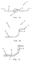
- Fig. 1a 1 shows a mold 1 for producing a molded skin for an instrument panel or for another vehicle interior trim part.
- the mold 1 has an inner side 2 designed to form a visible side of the molded skin.
- Form further comprises a raised portion 3, with which a bending of the molded skin is realized in the region of an opening to be introduced later.
- FIG. 1b A detail 4 of the form 1 is in Fig. 1b shown in more detail. As in Fig. 1b can be seen, the mold 1 on an additional recess 5, which is arranged in a transition to the raised portion 3 forming edge.
- a section of a molded skin 6 is shown, wherein the cutout corresponds to a section of the molded skin 6 produced by the region of the mold shown in detail 4.
- the molded skin 6 has a visible side 7 and a rear side 8.
- the visible side 7 is the side of the molded skin 6 which is shaped with the inner side 2 of the mold 1.
- the molded skin has an elevation 9, which in the present exemplary embodiment is rib-shaped and arranged on the visible side 7 of the molded skin 6.
- the molded skin 6 is arranged on a lower side 10 of a foaming tool.
- a carrier 11 wherein between the carrier 11 and molded skin 6, a gap is included.
- a reinforcing element 13 which is formed in the present embodiment as a wire ring, arranged.
- the arranged on the visible side 7 of the molded skin 6 elevation 9 is expressed from the bottom 10 of the foaming tool.
- the molded skin 6 forms an elevation 14 directed into the intermediate space 12.
- the directed into the gap 12 elevation 14 prevents the reinforcing element 13 can float upwards during backfoaming, since it produces a positive connection in this direction.
- a portion of an instrument panel is shown prior to the introduction of an opening.
- the illustrated area includes the portion of the molded skin 6 formed by the raised portion 3 of the mold 1.
- a foam layer 15 is arranged between carrier 11 and molded skin 6, a foam layer 15 is arranged.
- the area of the instrument panel between the two lines 16 is punched out.
- an air vent 17 is inserted into the opening formed thereby. It should be noted that incorporated in the same way in other vehicle interior trim parts openings and inserts'wie Heilausströmer 17 can be installed.
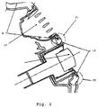
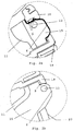
- FIG. 2 a section of a further embodiment of a preferred vehicle interior trim part (for example, an instrument panel) is shown, wherein the FIGS. 2a and 2b show the details marked 21 and 22 respectively.
- the instrument panel comprises a molded skin 6, a carrier 11, a foamed intermediate layer 15 and a reinforcing element 13. Again, the reinforcing element 13 is fixed by means of elevations 9 formed fixing elements.
- the means for fixing 9 are formed as applied to the molded skin 6 elevations, in principle, other configurations possible. For example, elevations could also be applied on the back 8 of the molded skin 6. Likewise, it would be possible that the elevations 9 are not formed as part of the molded skin, but are subsequently glued to these.
Landscapes
- Engineering & Computer Science (AREA)
- Mechanical Engineering (AREA)
- Vehicle Interior And Exterior Ornaments, Soundproofing, And Insulation (AREA)
- Instrument Panels (AREA)
- Casting Or Compression Moulding Of Plastics Or The Like (AREA)
Description
Die Erfindung betrifft ein Fahrzeuginnenverkleidungsteil das beispielsweise als eine Instrumententafel mit einer Formhaut, einer Zwischenschicht, einem Träger und mindestens einem in der Zwischenschicht angeordneten Verstärkungselement ausgebildet sein kann, sowie ein Verfahren zum Herstellen eines solchen Fahrzeuginnenverkleidungsteils.The invention relates to a vehicle interior trim part which may be formed, for example, as an instrument panel with a molded skin, an intermediate layer, a carrier and at least one reinforcing element arranged in the intermediate layer, and a method for producing such a vehicle interior trim part.
Nach dem Stand der Technik ist es bekannt, zur Herstellung eines Fahrzeuginnenverkleidungsteils wie beispielsweise einer Instrumententafel zunächst eine Formhaut durch Aufsprühen auf eine Form oder durch Rotationssintern herzustellen. Anschließend werden Formhaut und ein ebenfalls vorher hergestellter Träger in ein Schäumwerkzeug eingelegt und hinterschäumt. Um Biegungen der Formhaut, beispielsweise an einzubringenden Öffnungen für Luftausströmer, positionsgenau zu definieren, ist es bekannt, an den Stellen der beabsichtigten Biegungen der Formhaut Verstärkungselemente mit im Schäumwerkzeug anzuordnen.According to the prior art, it is known to first produce a molded skin by spraying on a mold or by rotational sintering for producing a vehicle interior trim part such as an instrument panel. Subsequently, molded skin and a likewise previously prepared carrier are placed in a foaming mold and backfoamed. To bends the molded skin, for example At openings to be introduced for air vents to define exact position, it is known to arrange at the points of the intended bends of the molded skin reinforcing elements in the foaming tool.
Hierbei ergibt sich jedoch das Problem, dass die Verstärkungselemente beim Hinterschäumen aufschwimmen können. Hierdurch verändert sich eine Position der Verstärkungselemente und somit der Biegungen der Formhaut. Schlimmstenfalls können die Verstärkungselemente in einen Bereich gelangen, in dem später eine Öffnung eingebracht werden soll. Dies kann dazu führen, dass Werkzeuge, welche zur Einbringung der Öffnungen verwendet werden, beschädigt werden. Wird die Öffnung beispielsweise ausgestanzt, kann ein in den Bereich der Öffnung verrutschtes Verstärkungselement zu einem Messerbruch bei der verwendeten Stanze führen.Here, however, there is the problem that the reinforcing elements can float during backfoaming. This changes a position of the reinforcing elements and thus the bends of the molded skin. In the worst case, the reinforcing elements can reach an area in which an opening is to be introduced later. This can result in damage to tools used to insert the openings. If the opening is punched out, for example, a reinforcing element slid into the region of the opening can lead to a knife break in the punch used.
Fahrzeuginnenverkleidungsteile mit in der Zwischenschicht angeordneten Verstärkungselementen sind beispielsweise aus den Druckschriften
Die gattungsgemäße Druckschrift
Dadurch, dass an der Formhaut Mittel zur Fixierung des Verstärkungselements angeordnet sind oder die Formhaut Mittel zur Fixierung des Verstärkungselements umfasst, wird ein Verrutschen des Verstärkungselements beim Hinterschäumen zuverlässig verhindert, so dass die Positionen der Biegungen der Formhaut zuverlässig definiert sind.Characterized in that are arranged on the molded skin means for fixing the reinforcing element or the Form skin comprises means for fixing the reinforcing member, slippage of the reinforcing member during the back-foaming is reliably prevented, so that the positions of the bends of the molded skin are reliably defined.
Die Mittel zur Fixierung sind als mindestens eine Erhöhung und besonders vorzugsweise als mindestens eine rippenförmige Erhöhung ausgebildet. Derartige Erhöhungen lassen sich einfach auf eine Formhaut aufbringen oder besonders bevorzugt mit der Formhaut als ein Bestandteil derselben herstellen.The means for fixing are designed as at least one elevation and particularly preferably as at least one rib-shaped elevation. Such elevations can be easily applied to a molded skin or more preferably made with the molded skin as a component thereof.
In einer weiteren vorteilhaften Ausführungsform sind die Mittel zur Fixierung auf einer Sichtseite der Formhaut angeordnet. Hierdurch können die Mittel zur Fixierung bereits in einer Form zur Herstellung der Formhaut berücksichtigt sein, derart, dass ein Negativ der Mittel zur Fixierung als Vertiefung in die Formoberfläche eingebracht ist. Ebenso können die Mittel zur Fixierung auf einer Rückseite der Formhaut angeordnet sein. Auch derart angeordnete Mittel zur Fixierung können leicht hergestellt werden, beispielsweise dadurch, dass in den Bereichen, in denen die Mittel zur Fixierung erwünscht sind, zusätzlicher Kunststoff beim Herstellen der Formhaut aufgebracht wird. Somit ist eine einteilige Ausbildung der Mittel zur Fixierung mit der Formhaut möglich. Die Mittel zur Fixierung sind dabei aus demselben Material wie die restliche Formhaut ausgebildet. Das Aufbringen des zusätzlichen Kunststoffs kann beispielsweise derart geschehen, dass zusätzlicher Kunststoff aufgesprüht wird, oder derart, dass die Bereiche, in denen Mittel zur Fixierung vorgesehen sein sollen, beim Rotationssintern verstärkt beheizt werden.In a further advantageous embodiment, the means for fixing are arranged on a visible side of the molded skin. As a result, the means for fixing can already be taken into account in a mold for the production of the molded skin, such that a negative of the means for fixing as a depression is introduced into the mold surface. Likewise, the means for fixing can be arranged on a rear side of the molded skin. Also arranged fixing means can be easily prepared, for example, in that in the areas in which the means for fixing are desired, additional plastic is applied during manufacture of the molded skin. Thus, a one-piece design of the means for fixing with the molded skin is possible. The means for fixing are formed from the same material as the rest of the molded skin. The application of the additional plastic can for example be done so that additional plastic is sprayed on, or such that the areas in which means are to be provided for fixing, are heated intensively during rotation sintering.
Die Mittel zur Fixierung zum indirekten Fixieren des Verstärkungselements sind derart ausgebildet und angeordnet, dass durch die Mittel zur Fixierung eine Verformung der Formhaut ausgelöst wird, durch welche das Verstärkungselement fixiert wird.The means for fixing for the indirect fixing of the reinforcing element are designed and arranged such that a deformation of the molded skin is triggered by the means for fixing, by which the reinforcing element is fixed.
In einer weiteren besonders bevorzugten Ausführungsform können die Mittel zur Fixierung zum formschlüssigen Halten des Verstärkungselements ausgebildet sein. Ein besonders einfaches Herstellen eines Verstärkungselements ist möglich, wenn dieses als ein Verstärkungsdraht ausgebildet ist.In a further particularly preferred embodiment, the means for fixing for positive retention of the reinforcing element may be formed. A particularly simple production of a reinforcing element is possible if this is formed as a reinforcing wire.
In einer weiteren besonders bevorzugten Ausführungsform weist die Instrumententafel bzw. das Fahrzeuginnenverkleidungsteil mindestens eine Öffnung auf. Bevorzugt kann die Öffnung einen Luftausströmer aufnehmen. Selbstverständlich kann die Öffnung auch zum Aufnehmen anderer Komponenten, beispielsweise eines Radios, Navigationsgerätes, Handschuhkastens, Lichtdrehschalters, Bedienelements
einer Scheinwerfer-Höhenverstellung oder dergleichen, ausgebildet sein. Weist die Instrumententafel bzw. das Fahrzeuginnenverkleidungsteil eine Öffnung auf, kann das Verstärkungselement bevorzugt die Öffnung umlaufend ausgebildet sein. Hierdurch kann eine Biegung der Formhaut um die Öffnung herum realisiert werden.In a further particularly preferred embodiment, the instrument panel or the vehicle interior trim part has at least one opening. Preferably, the opening can receive an air vent. Of course, the opening also for receiving other components, such as a radio, navigation device, glove box, light rotary switch, control element
a headlight height adjustment or the like may be formed. If the instrument panel or the vehicle interior trim part has an opening, the reinforcement element may preferably have the opening formed circumferentially. As a result, a bending of the molded skin around the opening can be realized.
Besonders bevorzugt kann das Verstärkungselement als ein die Öffnung umlaufender (Draht-)Ring ausgebildet sein. Insbesondere wenn das Verstärkungselement als die Öffnung umlaufendes Verstärkungselement ausgebildet ist, ist es vorteilhaft, wenn die Mittel zur Fixierung ebenfalls die Öffnung umlaufend angeordnet und ausgebildet sind.Particularly preferably, the reinforcing element can be designed as a (wire) ring surrounding the opening. In particular, when the reinforcing element is designed as a reinforcing element surrounding the opening is, it is advantageous if the means for fixing also the opening arranged circumferentially and formed.
Die Zwischenschicht kann besonders bevorzugt als geschäumte Zwischenschicht ausgebildet sein. Eine solche ist sehr einfach herzustellen.The intermediate layer may be particularly preferably formed as a foamed intermediate layer. Such is very easy to manufacture.
Weiterhin betrifft die Erfindung ein Verfahren zur Herstellung einer Instrumententafel bzw. eines Fahrzeuginnenverkleidungsteils. Bei einem solchen wird zunächst eine Form bereitgestellt, welche eine Formoberfläche aufweist, in der eine zusätzliche Vertiefung, welche zur Ausbildung der Mittel zur Fixierung dienen kann, angeordnet ist. Anschließend wird die Formhaut durch Aufsprühen auf die Form oder durch Rotationssintern unter Verwendung der Form hergestellt, derart, dass in die zusätzliche Vertiefung Kunststoff eindringt, welcher später eine auf die Formhaut aufgebrachte Erhöhung ausbildet.Furthermore, the invention relates to a method for producing an instrument panel or a vehicle interior trim part. In such a mold is first provided, which has a mold surface in which an additional recess, which can serve to form the means for fixing, is arranged. Subsequently, the molded skin is produced by spraying on the mold or by rotational sintering using the mold, such that plastic penetrates into the additional recess, which later forms an elevation applied to the molded skin.
Die so hergestellte Formhaut wird anschließend zusammen mit einem ebenfalls vorher hergestellten Träger sowie dem Verstärkungselement in ein Schäumwerkzeug eingelegt, wobei durch die auf die Formhaut aufgebrachte Erhöhung eine lokale zusätzliche Verformung der Formhaut hervorgerufen wird, durch die das Verstärkungselement fixiert wird. Anschließend wird die Formhaut hinterschäumt, derart, dass das Verstärkungselement in eine Schaumschicht eingebettet wird.The molded skin produced in this way is then inserted into a foaming tool together with a carrier, which has also been previously produced, and the reinforcement applied to the molded skin causes a local additional deformation of the molded skin, by means of which the reinforcing element is fixed. Subsequently, the molded skin is backfoamed, such that the reinforcing element is embedded in a foam layer.
Vorteilhafte Ausgestaltungen der Erfindung werden nachfolgend anhand der Figuren erläutert. Es zeigen:
- Fig. 1a
- eine Form zum Herstellen einer Formhaut,
- Fig. 1b
- ein Detail der in
Fig. 1a dargestellten Form, - Fig. 1c
- einen Bereich einer mit der Form aus den
Fign. 1a und 1b hergestellten Formhaut, - Fig. 1d
- eine Anordnung der Formhaut, eines Trägers sowie eines Verstärkungselements in einem Schäumwerkzeug,
- Fig. 1e
- eine Instrumententafel vor dem Einbringen einer Öffnung,
- Fig. 1f
- eine Instrumententafel nach dem Einbringen einer Öffnung und nach einem Einbau eines Luftausströmers,
- Fig. 2
- Ausschnitt einer Instrumententafel gemäß einer zweiten Ausführungsform der Erfindung
- Fig. 2a
- ein Detail der zweiten Ausführungsform einer vorteilhaften Instrumententafel und
- Fig. 2b
- ein weiteres Detail der zweiten Ausführungsform einer vorteilhaften Instrumententafel.
- Fig. 1a
- a mold for producing a molded skin,
- Fig. 1b
- a detail of in
Fig. 1a represented shape, - Fig. 1c
- an area of one with the shape of the
FIGS. 1a and 1b manufactured molded skin, - Fig. 1d
- an arrangement of the molded skin, a carrier and a reinforcing element in a foaming tool,
- Fig. 1e
- an instrument panel before inserting an opening,
- Fig. 1f
- an instrument panel after the introduction of an opening and after installation of an air vent,
- Fig. 2
- Section of an instrument panel according to a second embodiment of the invention
- Fig. 2a
- a detail of the second embodiment of an advantageous instrument panel and
- Fig. 2b
- another detail of the second embodiment of an advantageous instrument panel.
In
Ein Detail 4 der Form 1 ist in
In
In
In Fig. le ist ein Bereich einer Instrumententafel vor dem Einbringen einer Öffnung gezeigt. Der dargestellte Bereich beinhaltet den Abschnitt der Formhaut 6, der durch den erhöhten Bereich 3 der Form 1 geformt wurde. Zwischen Träger 11 und Formhaut 6 ist eine Schaumschicht 15 angeordnet. Anschließend wird der Bereich der Instrumententafel zwischen den beiden Linien 16 ausgestanzt. Wie in
In der
Angrenzend an die Formhaut 6 ist eine Blende 18 eines Luftausströmers zu erkennen. Außerdem ist eine Blende 19 eines Lichtdrehschalters dargestellt. In dem in
Claims (10)
- A vehicle interior trim part, in particular a dashboard, having a molded skin (6), an intermediate layer (15), a carrier (11) and at least one reinforcement element (13) arranged in the intermediate layer (15), characterized in that means for fixing (9) the reinforcement element (13) are arranged at the molded skin (6) or the molded skin includes means for fixing (9) the reinforcement element (13), wherein the means for fixing are formed as at least one elevated portion from the same material as the remaining molded skin and wherein the means for fixing (9) are formed and designed for the indirect fixing of the reinforcement element (13) by generating a deformation (14) of the molded skin (6).
- A vehicle interior trim part in accordance with claim 1, characterized in that the means for fixing (9) are formed as at least one rib-shaped elevated portion.
- A vehicle interior trim part in accordance with claim 1 or claim 2, characterized in that the means for fixing (9) are arranged on a visible side (7) of the molded skin (6) or on a rear side (8) of the molded skin (6).
- A vehicle interior trim part in accordance with one of the claims 1 to 3, characterized in that the means for fixing (9) are formed in one part with the molded skin (6).
- A vehicle interior trim part in accordance with one of the preceding claims, characterized in that the means for fixing (9) are formed for the shape-matched holding of the reinforcement element.
- A vehicle interior trim part in accordance with one of the preceding claims, characterized in that the reinforcement element (13) is formed as a reinforcement wire.
- A vehicle interior trim part in accordance with one of the preceding claims, characterized by an opening in which an air discharge installation is preferably arranged.
- A vehicle interior trim part in accordance with claim 8, characterized in that the reinforcement element (13) is formed as a reinforcement element running around the opening and preferably as a ring running around the opening, with the means for fixing (9) preferably being formed as means for fixing (9) running around the opening.
- A vehicle interior trim part in accordance with one of the preceding claims, characterized in that the intermediate layer (15) is formed as a foamed intermediate layer.
- A method of manufacturing a vehicle interior trim part comprising the steps:- providing a mold (1) which has a mold surface (2) having an additional recess (5);- manufacturing a molded skin (6) by spraying or rotational sintering using the mold (1) such that plastic penetrating into the additional recess (5) forms an elevated portion (9) from the same material as the remaining molded skin applied to the molded skin;- inserting the molded skin (6) and a reinforcement element (13) into a foaming mold (10), with a local additional deformation (14) of the molded skin being caused by the elevated portion (9) by which deformation the reinforcement element (13) is fixed; and- back foaming the molded skin (6) such that the reinforcement element is embedded into a foam layer (15).
Applications Claiming Priority (2)
| Application Number | Priority Date | Filing Date | Title |
|---|---|---|---|
| DE201010019153 DE102010019153A1 (en) | 2010-04-29 | 2010-04-29 | Instrument panel and method of making an instrument panel |
| PCT/EP2011/002131 WO2011134658A1 (en) | 2010-04-29 | 2011-04-28 | Vehicle interior trim part and method for producing a vehicle interior trim part |
Publications (2)
| Publication Number | Publication Date |
|---|---|
| EP2563620A1 EP2563620A1 (en) | 2013-03-06 |
| EP2563620B1 true EP2563620B1 (en) | 2016-04-13 |
Family
ID=44243562
Family Applications (1)
| Application Number | Title | Priority Date | Filing Date |
|---|---|---|---|
| EP11718294.9A Active EP2563620B1 (en) | 2010-04-29 | 2011-04-28 | Vehicle interior trim part and method for producing a vehicle interior trim part |
Country Status (5)
| Country | Link |
|---|---|
| US (1) | US8919845B2 (en) |
| EP (1) | EP2563620B1 (en) |
| CN (1) | CN102939219B (en) |
| DE (1) | DE102010019153A1 (en) |
| WO (1) | WO2011134658A1 (en) |
Families Citing this family (4)
| Publication number | Priority date | Publication date | Assignee | Title |
|---|---|---|---|---|
| DE102017209457A1 (en) * | 2017-06-02 | 2018-12-06 | Faurecia Innenraum Systeme Gmbh | Method and tool for producing a vehicle interior trim part and vehicle interior trim part |
| JP6802985B2 (en) * | 2017-07-25 | 2020-12-23 | トヨタ紡織株式会社 | Assembling structure of electrical parts to interior materials for vehicles |
| FR3070954B1 (en) * | 2017-09-11 | 2019-09-13 | Faurecia Interieur Industrie | DEFORMABLE EXTERNAL SURFACE FILLING ELEMENT AND ASSOCIATED VEHICLE |
| US11001309B2 (en) | 2019-04-08 | 2021-05-11 | Faurecia Interior Systems, Inc. | Instrument panel with reinforcement member |
Family Cites Families (10)
| Publication number | Priority date | Publication date | Assignee | Title |
|---|---|---|---|---|
| DE3016199A1 (en) * | 1980-04-26 | 1981-11-05 | Fa. Carl Freudenberg, 6940 Weinheim | DASHBOARD FOR MOTOR VEHICLES |
| DE3844636A1 (en) | 1988-11-02 | 1990-05-03 | Pelz Ernst Erpe Vertrieb | Prefabricated ceiling for motor vehicles |
| DE19704383A1 (en) | 1997-02-06 | 1998-08-13 | Moeller Plast Gmbh | Molding and process for its manufacture |
| DE19816017A1 (en) | 1998-04-09 | 1999-10-14 | Volkswagen Ag | Cover for an airbag arranged in a vehicle |
| DE19962551A1 (en) * | 1999-12-23 | 2001-01-11 | Daimler Chrysler Ag | Airbag assembly has foam cover whose foam structure is strengthened over at least half its base surface through flexible reinforcement fabric layer |
| US6475576B1 (en) * | 1999-12-30 | 2002-11-05 | Delphi Technologies, Inc. | Reinforced interior trim panel assembly and method |
| US6854783B2 (en) * | 2000-02-28 | 2005-02-15 | Mitsubishi Belting Ltd. | Multi-layer instrument panel having an accessory mounted thereon and a method of manufacturing the same |
| FR2852894B1 (en) * | 2003-03-31 | 2006-04-28 | Valeo Climatisation | DASHBOARD FOR MOTOR VEHICLE |
| US20080012382A1 (en) * | 2006-01-11 | 2008-01-17 | Evans Gregg S | Integration of buttons into a reaction injection molded automotive instrument panel skin |
| JP2008064188A (en) * | 2006-09-06 | 2008-03-21 | Bridgestone Corp | Ea (energy absorption) material |
-
2010
- 2010-04-29 DE DE201010019153 patent/DE102010019153A1/en not_active Ceased
-
2011
- 2011-04-28 WO PCT/EP2011/002131 patent/WO2011134658A1/en active Application Filing
- 2011-04-28 CN CN201180021701.8A patent/CN102939219B/en active Active
- 2011-04-28 EP EP11718294.9A patent/EP2563620B1/en active Active
- 2011-04-28 US US13/695,235 patent/US8919845B2/en active Active
Also Published As
| Publication number | Publication date |
|---|---|
| US20130200646A1 (en) | 2013-08-08 |
| CN102939219A (en) | 2013-02-20 |
| WO2011134658A1 (en) | 2011-11-03 |
| CN102939219B (en) | 2015-09-02 |
| EP2563620A1 (en) | 2013-03-06 |
| US8919845B2 (en) | 2014-12-30 |
| DE102010019153A1 (en) | 2011-11-03 |
Similar Documents
| Publication | Publication Date | Title |
|---|---|---|
| EP2598354B1 (en) | Method for producing a control element for an air-diffuser, control element for an air-diffuser, and air-diffuser | |
| DE102011050003A1 (en) | Injection molding device for producing molding, has plastic body and decorative material connected to plastic body, where two molding plates limits component cavity in closed state | |
| DE112006002513T5 (en) | Interior interior part of a work vehicle and method of manufacturing the same | |
| DE102017100330A1 (en) | Airbag assembly and method for its manufacture | |
| EP2563620B1 (en) | Vehicle interior trim part and method for producing a vehicle interior trim part | |
| EP1854681A2 (en) | Air duct for motor vehicle | |
| EP2113428B1 (en) | Airbag assembly for a motor vehicle | |
| DE102015114238B4 (en) | Attachment system and method for attaching a component to a vehicle body | |
| EP2335900B1 (en) | Method for producing a moulded interior panel | |
| EP1654607B1 (en) | Pedal bearing block | |
| DE102006061617A1 (en) | Fastening arrangement, in particular for holding a deflection fitting for a strap portion of a seatbelt in a vehicle, and method for attaching a deflection fitting on a support wall | |
| EP2015912B1 (en) | Method for producing a moulded part with an opening groove | |
| EP1298034A2 (en) | Roof part , especially internal lining for a vehicle roof , and method of its production | |
| WO2015078957A1 (en) | Airbag covering and method for producing same | |
| EP2790967B1 (en) | System including roof liner and catridge | |
| DE102012219107B4 (en) | Method for producing a vehicle interior trim part and vehicle interior trim part | |
| EP2091770B1 (en) | Fixture, in particular for a motor vehicle, with a first partial region and a second partial region which is integrally attached by means of a connecting region | |
| EP1996421B1 (en) | Decorative part for a motor vehicle, comprising an opening and a supporting element | |
| DE102005039925A1 (en) | B-column for assembly at vehicle structure, has sheet plate shaped part, and plastic carrier unit that is provided for intake of functional parts of safety belt system and is extruded at sheet plate shaped part | |
| DE102013214147A1 (en) | Airbag arrangement for a vehicle | |
| DE102007023988B4 (en) | Airbag module | |
| EP3501900B1 (en) | Internal module for a cargo compartment of a vehicle, cargo compartment cladding and method for producing an internal module | |
| DE102022105501A1 (en) | Method and injection molding tool for producing a component composite | |
| DE102019200222A1 (en) | Vehicle interior trim part, vehicle interior trim and method for producing a vehicle interior trim part | |
| DE202021105215U1 (en) | Mold assembly for making an instrument panel for a vehicle and instrument panel made therewith |
Legal Events
| Date | Code | Title | Description |
|---|---|---|---|
| PUAI | Public reference made under article 153(3) epc to a published international application that has entered the european phase |
Free format text: ORIGINAL CODE: 0009012 |
|
| 17P | Request for examination filed |
Effective date: 20121107 |
|
| AK | Designated contracting states |
Kind code of ref document: A1 Designated state(s): AL AT BE BG CH CY CZ DE DK EE ES FI FR GB GR HR HU IE IS IT LI LT LU LV MC MK MT NL NO PL PT RO RS SE SI SK SM TR |
|
| DAX | Request for extension of the european patent (deleted) | ||
| 17Q | First examination report despatched |
Effective date: 20140521 |
|
| REG | Reference to a national code |
Ref country code: DE Ref legal event code: R079 Ref document number: 502011009428 Country of ref document: DE Free format text: PREVIOUS MAIN CLASS: B60R0013020000 Ipc: B29C0044120000 |
|
| RIC1 | Information provided on ipc code assigned before grant |
Ipc: B60R 13/02 20060101ALI20150910BHEP Ipc: B29C 43/18 20060101ALI20150910BHEP Ipc: B29C 44/14 20060101ALI20150910BHEP Ipc: B29C 44/12 20060101AFI20150910BHEP |
|
| GRAP | Despatch of communication of intention to grant a patent |
Free format text: ORIGINAL CODE: EPIDOSNIGR1 |
|
| INTG | Intention to grant announced |
Effective date: 20151029 |
|
| GRAS | Grant fee paid |
Free format text: ORIGINAL CODE: EPIDOSNIGR3 |
|
| GRAA | (expected) grant |
Free format text: ORIGINAL CODE: 0009210 |
|
| AK | Designated contracting states |
Kind code of ref document: B1 Designated state(s): AL AT BE BG CH CY CZ DE DK EE ES FI FR GB GR HR HU IE IS IT LI LT LU LV MC MK MT NL NO PL PT RO RS SE SI SK SM TR |
|
| REG | Reference to a national code |
Ref country code: GB Ref legal event code: FG4D Free format text: NOT ENGLISH |
|
| REG | Reference to a national code |
Ref country code: AT Ref legal event code: REF Ref document number: 789622 Country of ref document: AT Kind code of ref document: T Effective date: 20160415 Ref country code: CH Ref legal event code: EP |
|
| REG | Reference to a national code |
Ref country code: IE Ref legal event code: FG4D Free format text: LANGUAGE OF EP DOCUMENT: GERMAN |
|
| REG | Reference to a national code |
Ref country code: FR Ref legal event code: PLFP Year of fee payment: 6 |
|
| REG | Reference to a national code |
Ref country code: DE Ref legal event code: R096 Ref document number: 502011009428 Country of ref document: DE |
|
| REG | Reference to a national code |
Ref country code: LT Ref legal event code: MG4D |
|
| PG25 | Lapsed in a contracting state [announced via postgrant information from national office to epo] |
Ref country code: BE Free format text: LAPSE BECAUSE OF NON-PAYMENT OF DUE FEES Effective date: 20160430 |
|
| REG | Reference to a national code |
Ref country code: NL Ref legal event code: MP Effective date: 20160413 |
|
| PG25 | Lapsed in a contracting state [announced via postgrant information from national office to epo] |
Ref country code: FI Free format text: LAPSE BECAUSE OF FAILURE TO SUBMIT A TRANSLATION OF THE DESCRIPTION OR TO PAY THE FEE WITHIN THE PRESCRIBED TIME-LIMIT Effective date: 20160413 Ref country code: PL Free format text: LAPSE BECAUSE OF FAILURE TO SUBMIT A TRANSLATION OF THE DESCRIPTION OR TO PAY THE FEE WITHIN THE PRESCRIBED TIME-LIMIT Effective date: 20160413 Ref country code: NO Free format text: LAPSE BECAUSE OF FAILURE TO SUBMIT A TRANSLATION OF THE DESCRIPTION OR TO PAY THE FEE WITHIN THE PRESCRIBED TIME-LIMIT Effective date: 20160713 Ref country code: NL Free format text: LAPSE BECAUSE OF FAILURE TO SUBMIT A TRANSLATION OF THE DESCRIPTION OR TO PAY THE FEE WITHIN THE PRESCRIBED TIME-LIMIT Effective date: 20160413 Ref country code: LT Free format text: LAPSE BECAUSE OF FAILURE TO SUBMIT A TRANSLATION OF THE DESCRIPTION OR TO PAY THE FEE WITHIN THE PRESCRIBED TIME-LIMIT Effective date: 20160413 |
|
| PG25 | Lapsed in a contracting state [announced via postgrant information from national office to epo] |
Ref country code: PT Free format text: LAPSE BECAUSE OF FAILURE TO SUBMIT A TRANSLATION OF THE DESCRIPTION OR TO PAY THE FEE WITHIN THE PRESCRIBED TIME-LIMIT Effective date: 20160816 Ref country code: RS Free format text: LAPSE BECAUSE OF FAILURE TO SUBMIT A TRANSLATION OF THE DESCRIPTION OR TO PAY THE FEE WITHIN THE PRESCRIBED TIME-LIMIT Effective date: 20160413 Ref country code: HR Free format text: LAPSE BECAUSE OF FAILURE TO SUBMIT A TRANSLATION OF THE DESCRIPTION OR TO PAY THE FEE WITHIN THE PRESCRIBED TIME-LIMIT Effective date: 20160413 Ref country code: SE Free format text: LAPSE BECAUSE OF FAILURE TO SUBMIT A TRANSLATION OF THE DESCRIPTION OR TO PAY THE FEE WITHIN THE PRESCRIBED TIME-LIMIT Effective date: 20160413 Ref country code: GR Free format text: LAPSE BECAUSE OF FAILURE TO SUBMIT A TRANSLATION OF THE DESCRIPTION OR TO PAY THE FEE WITHIN THE PRESCRIBED TIME-LIMIT Effective date: 20160714 Ref country code: ES Free format text: LAPSE BECAUSE OF FAILURE TO SUBMIT A TRANSLATION OF THE DESCRIPTION OR TO PAY THE FEE WITHIN THE PRESCRIBED TIME-LIMIT Effective date: 20160413 Ref country code: LV Free format text: LAPSE BECAUSE OF FAILURE TO SUBMIT A TRANSLATION OF THE DESCRIPTION OR TO PAY THE FEE WITHIN THE PRESCRIBED TIME-LIMIT Effective date: 20160413 |
|
| REG | Reference to a national code |
Ref country code: CH Ref legal event code: PL |
|
| PG25 | Lapsed in a contracting state [announced via postgrant information from national office to epo] |
Ref country code: IT Free format text: LAPSE BECAUSE OF FAILURE TO SUBMIT A TRANSLATION OF THE DESCRIPTION OR TO PAY THE FEE WITHIN THE PRESCRIBED TIME-LIMIT Effective date: 20160413 |
|
| REG | Reference to a national code |
Ref country code: DE Ref legal event code: R097 Ref document number: 502011009428 Country of ref document: DE |
|
| REG | Reference to a national code |
Ref country code: IE Ref legal event code: MM4A |
|
| PG25 | Lapsed in a contracting state [announced via postgrant information from national office to epo] |
Ref country code: RO Free format text: LAPSE BECAUSE OF FAILURE TO SUBMIT A TRANSLATION OF THE DESCRIPTION OR TO PAY THE FEE WITHIN THE PRESCRIBED TIME-LIMIT Effective date: 20160413 Ref country code: DK Free format text: LAPSE BECAUSE OF FAILURE TO SUBMIT A TRANSLATION OF THE DESCRIPTION OR TO PAY THE FEE WITHIN THE PRESCRIBED TIME-LIMIT Effective date: 20160413 Ref country code: CH Free format text: LAPSE BECAUSE OF NON-PAYMENT OF DUE FEES Effective date: 20160430 Ref country code: LI Free format text: LAPSE BECAUSE OF NON-PAYMENT OF DUE FEES Effective date: 20160430 Ref country code: EE Free format text: LAPSE BECAUSE OF FAILURE TO SUBMIT A TRANSLATION OF THE DESCRIPTION OR TO PAY THE FEE WITHIN THE PRESCRIBED TIME-LIMIT Effective date: 20160413 Ref country code: CZ Free format text: LAPSE BECAUSE OF FAILURE TO SUBMIT A TRANSLATION OF THE DESCRIPTION OR TO PAY THE FEE WITHIN THE PRESCRIBED TIME-LIMIT Effective date: 20160413 Ref country code: SK Free format text: LAPSE BECAUSE OF FAILURE TO SUBMIT A TRANSLATION OF THE DESCRIPTION OR TO PAY THE FEE WITHIN THE PRESCRIBED TIME-LIMIT Effective date: 20160413 Ref country code: MC Free format text: LAPSE BECAUSE OF FAILURE TO SUBMIT A TRANSLATION OF THE DESCRIPTION OR TO PAY THE FEE WITHIN THE PRESCRIBED TIME-LIMIT Effective date: 20160413 |
|
| PLBE | No opposition filed within time limit |
Free format text: ORIGINAL CODE: 0009261 |
|
| STAA | Information on the status of an ep patent application or granted ep patent |
Free format text: STATUS: NO OPPOSITION FILED WITHIN TIME LIMIT |
|
| PG25 | Lapsed in a contracting state [announced via postgrant information from national office to epo] |
Ref country code: SM Free format text: LAPSE BECAUSE OF FAILURE TO SUBMIT A TRANSLATION OF THE DESCRIPTION OR TO PAY THE FEE WITHIN THE PRESCRIBED TIME-LIMIT Effective date: 20160413 |
|
| 26N | No opposition filed |
Effective date: 20170116 |
|
| GBPC | Gb: european patent ceased through non-payment of renewal fee |
Effective date: 20160713 |
|
| REG | Reference to a national code |
Ref country code: FR Ref legal event code: PLFP Year of fee payment: 7 |
|
| PG25 | Lapsed in a contracting state [announced via postgrant information from national office to epo] |
Ref country code: SI Free format text: LAPSE BECAUSE OF FAILURE TO SUBMIT A TRANSLATION OF THE DESCRIPTION OR TO PAY THE FEE WITHIN THE PRESCRIBED TIME-LIMIT Effective date: 20160413 Ref country code: GB Free format text: LAPSE BECAUSE OF NON-PAYMENT OF DUE FEES Effective date: 20160713 Ref country code: IE Free format text: LAPSE BECAUSE OF NON-PAYMENT OF DUE FEES Effective date: 20160428 |
|
| REG | Reference to a national code |
Ref country code: AT Ref legal event code: MM01 Ref document number: 789622 Country of ref document: AT Kind code of ref document: T Effective date: 20160428 |
|
| PG25 | Lapsed in a contracting state [announced via postgrant information from national office to epo] |
Ref country code: AT Free format text: LAPSE BECAUSE OF NON-PAYMENT OF DUE FEES Effective date: 20160428 |
|
| REG | Reference to a national code |
Ref country code: FR Ref legal event code: PLFP Year of fee payment: 8 |
|
| PG25 | Lapsed in a contracting state [announced via postgrant information from national office to epo] |
Ref country code: HU Free format text: LAPSE BECAUSE OF FAILURE TO SUBMIT A TRANSLATION OF THE DESCRIPTION OR TO PAY THE FEE WITHIN THE PRESCRIBED TIME-LIMIT; INVALID AB INITIO Effective date: 20110428 Ref country code: CY Free format text: LAPSE BECAUSE OF FAILURE TO SUBMIT A TRANSLATION OF THE DESCRIPTION OR TO PAY THE FEE WITHIN THE PRESCRIBED TIME-LIMIT Effective date: 20160413 |
|
| PG25 | Lapsed in a contracting state [announced via postgrant information from national office to epo] |
Ref country code: LU Free format text: LAPSE BECAUSE OF NON-PAYMENT OF DUE FEES Effective date: 20160428 Ref country code: TR Free format text: LAPSE BECAUSE OF FAILURE TO SUBMIT A TRANSLATION OF THE DESCRIPTION OR TO PAY THE FEE WITHIN THE PRESCRIBED TIME-LIMIT Effective date: 20160413 Ref country code: MK Free format text: LAPSE BECAUSE OF FAILURE TO SUBMIT A TRANSLATION OF THE DESCRIPTION OR TO PAY THE FEE WITHIN THE PRESCRIBED TIME-LIMIT Effective date: 20160413 Ref country code: IS Free format text: LAPSE BECAUSE OF FAILURE TO SUBMIT A TRANSLATION OF THE DESCRIPTION OR TO PAY THE FEE WITHIN THE PRESCRIBED TIME-LIMIT Effective date: 20160413 Ref country code: MT Free format text: LAPSE BECAUSE OF FAILURE TO SUBMIT A TRANSLATION OF THE DESCRIPTION OR TO PAY THE FEE WITHIN THE PRESCRIBED TIME-LIMIT Effective date: 20160413 |
|
| PG25 | Lapsed in a contracting state [announced via postgrant information from national office to epo] |
Ref country code: BG Free format text: LAPSE BECAUSE OF FAILURE TO SUBMIT A TRANSLATION OF THE DESCRIPTION OR TO PAY THE FEE WITHIN THE PRESCRIBED TIME-LIMIT Effective date: 20160413 |
|
| PG25 | Lapsed in a contracting state [announced via postgrant information from national office to epo] |
Ref country code: AL Free format text: LAPSE BECAUSE OF FAILURE TO SUBMIT A TRANSLATION OF THE DESCRIPTION OR TO PAY THE FEE WITHIN THE PRESCRIBED TIME-LIMIT Effective date: 20160413 |
|
| PGFP | Annual fee paid to national office [announced via postgrant information from national office to epo] |
Ref country code: FR Payment date: 20200319 Year of fee payment: 10 |
|
| PG25 | Lapsed in a contracting state [announced via postgrant information from national office to epo] |
Ref country code: FR Free format text: LAPSE BECAUSE OF NON-PAYMENT OF DUE FEES Effective date: 20210430 |
|
| PGFP | Annual fee paid to national office [announced via postgrant information from national office to epo] |
Ref country code: DE Payment date: 20240320 Year of fee payment: 14 |