EP2113428B1 - Airbag assembly for a motor vehicle - Google Patents
Airbag assembly for a motor vehicle Download PDFInfo
- Publication number
- EP2113428B1 EP2113428B1 EP09005579A EP09005579A EP2113428B1 EP 2113428 B1 EP2113428 B1 EP 2113428B1 EP 09005579 A EP09005579 A EP 09005579A EP 09005579 A EP09005579 A EP 09005579A EP 2113428 B1 EP2113428 B1 EP 2113428B1
- Authority
- EP
- European Patent Office
- Prior art keywords
- airbag
- shot
- duct
- assembly according
- airbag assembly
- Prior art date
- Legal status (The legal status is an assumption and is not a legal conclusion. Google has not performed a legal analysis and makes no representation as to the accuracy of the status listed.)
- Active
Links
Images


Classifications
-
- B—PERFORMING OPERATIONS; TRANSPORTING
- B60—VEHICLES IN GENERAL
- B60R—VEHICLES, VEHICLE FITTINGS, OR VEHICLE PARTS, NOT OTHERWISE PROVIDED FOR
- B60R21/00—Arrangements or fittings on vehicles for protecting or preventing injuries to occupants or pedestrians in case of accidents or other traffic risks
- B60R21/02—Occupant safety arrangements or fittings, e.g. crash pads
- B60R21/16—Inflatable occupant restraints or confinements designed to inflate upon impact or impending impact, e.g. air bags
- B60R21/20—Arrangements for storing inflatable members in their non-use or deflated condition; Arrangement or mounting of air bag modules or components
- B60R21/205—Arrangements for storing inflatable members in their non-use or deflated condition; Arrangement or mounting of air bag modules or components in dashboards
-
- B—PERFORMING OPERATIONS; TRANSPORTING
- B23—MACHINE TOOLS; METAL-WORKING NOT OTHERWISE PROVIDED FOR
- B23K—SOLDERING OR UNSOLDERING; WELDING; CLADDING OR PLATING BY SOLDERING OR WELDING; CUTTING BY APPLYING HEAT LOCALLY, e.g. FLAME CUTTING; WORKING BY LASER BEAM
- B23K26/00—Working by laser beam, e.g. welding, cutting or boring
- B23K26/36—Removing material
- B23K26/362—Laser etching
- B23K26/364—Laser etching for making a groove or trench, e.g. for scribing a break initiation groove
-
- B—PERFORMING OPERATIONS; TRANSPORTING
- B60—VEHICLES IN GENERAL
- B60R—VEHICLES, VEHICLE FITTINGS, OR VEHICLE PARTS, NOT OTHERWISE PROVIDED FOR
- B60R21/00—Arrangements or fittings on vehicles for protecting or preventing injuries to occupants or pedestrians in case of accidents or other traffic risks
- B60R21/02—Occupant safety arrangements or fittings, e.g. crash pads
- B60R21/16—Inflatable occupant restraints or confinements designed to inflate upon impact or impending impact, e.g. air bags
- B60R21/20—Arrangements for storing inflatable members in their non-use or deflated condition; Arrangement or mounting of air bag modules or components
- B60R21/215—Arrangements for storing inflatable members in their non-use or deflated condition; Arrangement or mounting of air bag modules or components characterised by the covers for the inflatable member
- B60R21/2165—Arrangements for storing inflatable members in their non-use or deflated condition; Arrangement or mounting of air bag modules or components characterised by the covers for the inflatable member characterised by a tear line for defining a deployment opening
-
- B—PERFORMING OPERATIONS; TRANSPORTING
- B60—VEHICLES IN GENERAL
- B60R—VEHICLES, VEHICLE FITTINGS, OR VEHICLE PARTS, NOT OTHERWISE PROVIDED FOR
- B60R21/00—Arrangements or fittings on vehicles for protecting or preventing injuries to occupants or pedestrians in case of accidents or other traffic risks
- B60R21/02—Occupant safety arrangements or fittings, e.g. crash pads
- B60R21/16—Inflatable occupant restraints or confinements designed to inflate upon impact or impending impact, e.g. air bags
- B60R2021/161—Inflatable occupant restraints or confinements designed to inflate upon impact or impending impact, e.g. air bags characterised by additional means for controlling deployment trajectory
-
- B—PERFORMING OPERATIONS; TRANSPORTING
- B60—VEHICLES IN GENERAL
- B60R—VEHICLES, VEHICLE FITTINGS, OR VEHICLE PARTS, NOT OTHERWISE PROVIDED FOR
- B60R21/00—Arrangements or fittings on vehicles for protecting or preventing injuries to occupants or pedestrians in case of accidents or other traffic risks
- B60R21/02—Occupant safety arrangements or fittings, e.g. crash pads
- B60R21/16—Inflatable occupant restraints or confinements designed to inflate upon impact or impending impact, e.g. air bags
- B60R21/20—Arrangements for storing inflatable members in their non-use or deflated condition; Arrangement or mounting of air bag modules or components
- B60R21/215—Arrangements for storing inflatable members in their non-use or deflated condition; Arrangement or mounting of air bag modules or components characterised by the covers for the inflatable member
- B60R2021/21537—Arrangements for storing inflatable members in their non-use or deflated condition; Arrangement or mounting of air bag modules or components characterised by the covers for the inflatable member characterised by hinges
Definitions
- the invention relates to an airbag arrangement for a motor vehicle according to the preamble of claim 1.
- Such an airbag arrangement is provided in the passenger area of an instrument panel of the motor vehicle or other vehicle interior trim with comparable construction.
- an airbag assembly in which the underside of a dashboard base support as a separate part of a shot channel wall is mounted, which limits a shot channel.
- the firing channel is covered by an airbag cover.
- an airbag module may be provided within the firing channel.
- the airbag module may be suspended in the firing channel wall, for example via lateral hooks.
- a sufficiently large mounting gap is provided between the airbag module and the firing channel wall.
- the size of the airbag cover is determined by the cross section of the firing channel in which the airbag module is mounted.
- the firing channel wall is brought approximately at right angles to the airbag cover.
- a wall guide is manufacturing technology a disadvantage when incorporating a predetermined tear line between the airbag cover and the firing channel.
- the predetermined tear line is usually produced by material weakening.
- the introduced for this purpose in the firing channel tool such as a laser head for a laser attenuation, can be recognized with his tool head only in greater oblique position on the inside of the firing channel. Due to the inclination of the tool therefore a disadvantageous material thickness of the instrument panel must be overcome in order to penetrate up to a predetermined residual material thickness. The energy input is therefore disadvantageously increased.
- a generic airbag assembly with a funnel-shaped firing channel wall is known, which tapers in the direction of an outlet slot.
- From the US 2006/0214399 A and from the EP 1 880 906 A1 In each case a further airbag arrangement is known, in which the airbag module is hooked with lateral hook elements in mounting openings of the firing channel wall.
- An airbag arrangement is likewise known in which an airbag cover which covers the airbag outlet opening is articulated via a film hinge to a firing channel wall.
- the object of the invention is to provide an airbag assembly for a motor vehicle, which can be produced in a simple production with an airbag cover of reduced size.
- the firing channel tapers with its firing channel cross-section in the direction of the airbag cover.
- the firing channel is therefore not brought in a straight line in the firing direction of the airbag module to the underside of the instrument panel. Rather, the firing channel tapers at least partially in the weft direction of the airbag module, whereby the size of the airbag cover is reduced.
- the cross section of the firing channel remains sufficiently large at its end remote from the bag cover to achieve a simple airbag module assembly.
- the firing channel may preferably have at least one tapered section whose end remote from the airbag cover merges into a firing channel section with a larger firing channel cross section, and whose end facing the airbag cover merges into a firing channel section with a smaller firing channel cross section.
- the airbag module can be mounted on the firing channel part with a larger cross-section, in particular mounted in a mounting hole.
- the above-mentioned taper portion of the weft channel is preferably provided between the mounting portion for the airbag module and the airbag cover.
- the firing channel wall is formed in the weft direction of the airbag module with reduced rigidity.
- Such a wall geometry is advantageous in terms of a reduction of forces that are introduced in the airbag activation of the airbag module via the mounting portion in the firing channel. Namely, in the airbag shot, the firing channel wall can be elastically deformed accordion-like at its taper portion, whereby the introduction of force into the instrument panel is reduced after the airbag activation.
- the weft channel with smaller shot channel cross-section can be formed directly as a peripheral edge, which limits only an airbag passage opening without longitudinal extension in the airbag weft direction. In this way, despite a reduced airbag cover, a sufficiently large mounting gap between the airbag module and the laterally limiting firing channel wall is ensured.
- the firing channel wall can be connected as a separate component to a base carrier of an instrument panel.
- the firing channel wall can have a carrying section, for example a carrying leg, with which the firing channel wall is supported on the instrument panel base carrier.
- the predetermined tear line can be incorporated by way of example by material weakening by means of a milling cutter or a laser device.
- a tool head is inserted into the firing channel.
- the tool head can be brought into contact with the inside of the weft channel.
- the firing channel can have on the inside an undercut, which is stepped counter to the firing direction of the airbag module to the outside.
- a mounting space for the tool such as the laser head or the milling head, provided. This can be moved into the mounting space inside and supported on the gradation of the mounting space.
- a nearly tangential laser attenuation between the firing channel and the airbag cover can be achieved with a slight inclination of the tool. Due to the small inclination of the laser head, in turn, its focus position can be brought within the material to be weakened near the residual wall thickness, whereby the processing quality increases.
- the above-mentioned undercut for the tooling in dual function at the same time form the taper portion of the firing channel.
- the airbag cover may be connected to the firing channel wall in the same material and / or in one piece, for example as a plastic injection-molded part.
- the airbag cover can pass into the firing channel wall via an integral loop of film hinge which protrudes into the firing channel in the manner of a loop.
- the film hinge portion may extend substantially over the entire length of an edge side of the airbag cover and define an upwardly open, channel-shaped free space. The other edge sides of the airbag cover, however, can be moved from the already mentioned predetermined tear.
- the airbag cover can easily open around a hinge axis of the film hinge section.
- the above-mentioned, limited by Filmscharnlerabsacrificing, trough-shaped space is not filled by the top of the dashboard provided foam layer, but rather separated from this.
- the foam layer is applied to the top of the base support along with a slush skin after the assembly of the firing channel on the instrument panel base support in a known per se foaming process.
- an additional covering element can be provided, with which this clearance is covered.
- the cover can preferably integrally material and / or integrally integrated on the airbag cover, in particular be molded there by injection molding.
- a filling element can be inserted into the free space of the film hinge section substantially without its own dimensional stability, for example a soft-viewing element, before the foaming process.
- the filling element prevents on the one hand during the foaming an intrusion of foam material in the free space.
- the filling element is designed sufficiently soft that can easily open when the airbag activation of the bag.
- lamination is also possible as an alternative.
- Another, subsequently described aspect of the invention relates to the mounting gap between the firing channel wall and the airbag module inserted therein.
- the mounting gap has to be dimensioned large enough to ensure easy assembly and disassembly of the airbag module.
- the mounting gap is too large, there is a risk that, after the airbag has deployed, the airbag will partially unfold into the mounting gap.
- the airbag arrangement according to the invention has an actuating element which, when the airbag module is triggered, presses the firing channel wall in the direction of the airbag module.
- the actuating element in a double function is at the same time the airbag module-side mounting element, with which the airbag module can be suspended in the firing channel wall.
- the at least one mounting element can protrude through a corresponding mounting opening of the firing channel wall and be supported with an angled end on an outside oblique surface of the firing channel wall.
- the mounting element interacts with the inclined surface of the firing channel wall in an airbag triggering as follows: Immediately after the triggering of the airbag module, it is known that a kickback movement of the airbag module takes place counter to the firing direction. During the non-return movement of the airbag module, its mounting element presses against the oblique surface of the firing channel wall, which extends obliquely outwards against the firing channel direction. The firing channel wall is therefore deflected in accordance with elastic design to the inside. As a result of this deformation of the firing channel wall inwards, the mounting gap surrounding the airbag module becomes reduced, so that the unfolding airbag can not dip into the mounting gap.
- the above inclined surface may preferably be provided by the above-mentioned taper portion of the shot channel wall, which tapers the shot channel cross section toward the air bag cover.
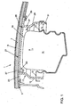
- Fig. 1 is shown in a roughly schematic side sectional view of a passenger-side instrument panel 1 for a motor vehicle. Below the instrument panel 1, an airbag assembly 3 is provided.
- the instrument panel has an instrument panel foundation support 5 with a foamed foam layer 7, on the upper side of which a slush skin 9 is provided.
- the airbag assembly 3 has a per se known airbag module 11, which is inserted via lateral mounting arms 13 in opposite mounting holes 15 of a firing channel wall 17 of the airbag assembly 3.
- the firing channel wall 17 surrounds the airbag module 11 in the manner of a frame and can be of rectangular cross-section by way of example.
- the firing channel wall 17 is embodied here by way of example as a separate insert component from the instrument panel base carrier 5.
- the firing channel wall 17 further defines a firing channel 19, with which an airbag unfolding from the airbag module 11 is guided in the direction of an airbag cover 21.
- the airbag cover 21 closes the firing channel 19 at the top and extends substantially flush with a laterally protruding from the firing channel wall 17 holding frame 23.
- the firing channel wall 17 is supported with its support frame 23 on a support shoulder 25 of the instrument panel base support 5, which is opposite to the base support 5 is stepped and limits a mounting opening of the base support 5.
- the holding frame 23 terminates approximately flush with the top of the base support 5.
- the firing channel wall 17 projects with a first wall portion 27 at right angles from the holding frame 23 against a firing direction 1 of the airbag module 11 downwards and merges into a tapering section 29.
- a second wall part 31 connects, which runs approximately parallel to the first wall part 27. The firing channel cross-section thus tapers in the direction of the airbag cover 21, whereby it is reduced in its surface area.
- the mounting holes 15 for suspending the airbag module 11 are according to the Fig. 1 provided on the second wall portion 31 with a larger shot channel cross-section.
- a mounting gap s 1 formed between the airbag module 11 and the second wall part 31 of the firing channel wall 17 is therefore made correspondingly large in order to ensure simple assembly and disassembly of the airbag module 11.
- the airbag module 11 is dimensioned such that its upper side protrudes into the first wall part 27 of the firing channel wall 17, in which the mounting gap s 2 is reduced. In the case of activation of the airbag assembly s 2 therefore reduces the risk that the unfolding airbag partially displaced in the larger mounting gap s 1 due to the reduced mounting gap.
- the integrated in the firing channel wall 17 airbag cover 21 is on one side via a film hinge section 33 with the Shot channel wall 17 connected.
- the film hinge section protrudes in accordance with Fig. 1 like a loop into the firing channel 19.
- the film hinge section 33 extends along an airbag cover edge side, while the remaining airbag cover edge sides are delimited by a predetermined tear line 35.
- the film hinge portion 33 defines an upwardly open, channel-shaped free space 37, which in the Fig. 1 to 3 is covered at the top by a cover 39.
- the cover 39 is integrally formed on the airbag cover 21 and is supported according to the Fig. 1 to 3 with its free end on the opposite upper-side bending edge of the film hinge portion 33 from.
- the cover 39 ensures that during a foaming process in which the foam layer 7 is applied to the base support 5, no foaming material can get into the space 37.
- In the channel-shaped free space 37 of the film hinge portion 33 also support walls may be arranged, on which the cover 39 can be supported.
- the frame-shaped shot channel wall 17 is manufactured separately from the base carrier 5 in a plastic injection molding process.
- the material of the firing channel wall is optimized according to the necessary concerns with respect to the elasticity.
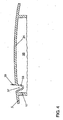
- the firing channel wall 17 with integrated airbag cover 21 is shown in its production position during plastic injection molding. Consequently, the lameilenIndia cover 39 is placed vertically upwards to allow a simple demolding movement of the injection molding tools not shown here and to avoid undercuts.
- the firing channel wall 17 is inserted, starting from the, the vehicle interior facing side of the instrument panel base support 5 in the mounting hole and supported with the support frame 23 on the support shoulder 25 of the base support 5.
- the foam layer 7 and the slush skin 9 are applied under pressure to the upper side of the base support 5.
- the support frame 23 can be connected, for example by ultrasonic welding with the support shoulder 25.
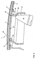
- the desired breaking line 35 is introduced into the instrument panel 1 by means of laser processing.
- a laser head 41 of a laser processing device is inserted into the firing channel 19 with still dismantled airbag module 11 and brought into contact with the firing channel inside for a stable tool guide.
- the laser head 41 projects partially into an annular mounting space 43 which is provided by the tapering section 29 and on the inside forms an undercut which is widened counter to the weft direction I.
- Fig. 2 Is the laser head 41 brought with its front side at a transition edge between the first wall portion 27 and the taper portion 29 in approach.
- a laser cut can be generated at a much steeper angle. Due to the steeper machining angle, the material thickness of the instrument panel to be overcome is reduced, as a result of which the energy input can also be reduced.
- the tool approach edge 45 between the first wall portion 27 and the taper portion 29 is positioned at a predetermined altitude, in which a process-technically favorable focus position of the laser beam results near a residual wall thickness.
- the airbag module 11 suspended in the firing channel wall 17 initially moves counter to the firing direction 1, so that the firing channel wall 17 is pulled apart like an accordion with its two wall parts 27, 31, thereby dampening the non-return movement.
- the firing channel wall 17 is compressed like an accordion.
- the deploying airbag of the airbag module 11 ruptures the airbag cover 11 about a hinge axis formed by the film hinge section 33. Because according to the The first embodiment of the space defined by the film hinge portion 33 free space 37 is foam-free, a smooth opening movement of the airbag cover 11 is ensured here.
- FIG. 5 is shown an airbag assembly according to the second comparative example, whose components and operation are identical to those of the first embodiment.
- first comparative example no additional cover element 39, which covers the free space 37 of the film hinge section 33, is integrated in the airbag cover 21.
- a filling element 47 is inserted into the free space 37 before the foaming process.
- the filling element 47 is in comparison to the foam layer 7 substantially without dimensional stability. The filling element 47 therefore does not affect the opening movement of the airbag cover 21, the hinge axis.
- FIG. 6 an airbag assembly according to the third comparative example is shown.
- the tapering section 29 is used with its upper, the airbag cover 21 facing end up to the support frame 23, namely omitting the first wall portion 27.
- the tapering section 29 therefore limited with its upper peripheral edge 48 directly an airbag passage opening ,
- the airbag cover surface is designed much smaller than the firing channel cross section of the second wall portion 31 of the firing channel wall 17. With the reduced airbag cover 21 can be reliably prevented a disc occupant contact.
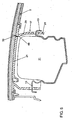
- FIG. 7 an airbag assembly according to the embodiment of the invention is shown.
- the mounting openings 15 for suspending the airbag module 11 are not provided in the second wall part 31 with an enlarged channel cross section, but in the first wall part 27 with a reduced cross section.
- the projecting through the mounting holes 15 side mounting arms 13 of the airbag module 11 are not supported directly on the opening edge of the mounting holes 15. Rather, the lateral mounting arms 13 are supported with angled support legs 49 on the outside of the tapered section 29.
- the tapering section 29 therefore forms in a double function on the outside an inclined deflection 51.
- the deflection surface 51 acts in an airbag deployment with the support legs 49 of the mounting arms 13 of the airbag module 11 together so that the firing channel wall 17 is pressed inwardly against the airbag module 11 by the above-mentioned non-return movement of the airbag module 11. This reduces the mounting gap s. In this way, it is reliably prevented that the deploying airbag is partially immersed in the mounting gap s, whereby the functionality of the airbag is ensured.
Landscapes
- Engineering & Computer Science (AREA)
- Mechanical Engineering (AREA)
- Physics & Mathematics (AREA)
- Optics & Photonics (AREA)
- Plasma & Fusion (AREA)
- Air Bags (AREA)
Description
Die Erfindung betrifft eine Airbaganordnung für ein Kraftfahrzeug nach dem Oberbegriff des Patentanspruches 1.The invention relates to an airbag arrangement for a motor vehicle according to the preamble of claim 1.
Eine derartige Airbaganordnung ist im Beifahrerbereich einer Instrumententafel des Kraftfahrzeuges vorgesehen oder anderen Fahrzeug-Innenverkleidungen mit vergleich-barem Aufbau.Such an airbag arrangement is provided in the passenger area of an instrument panel of the motor vehicle or other vehicle interior trim with comparable construction.
Aus der
Innerhalb des Schusskanals kann ein Airbagmoduls vorgesehen sein: Das Airbagmodul kann beispielsweise über seitliche Haken in der Schusskanalwand eingehängt sein. Für eine einfache Montage des Airbagmoduls ist ein ausreichend großer Montagespalt zwischen dem Airbagmodul und der Schusskanalwand vorgesehen.Within the firing channel, an airbag module may be provided. The airbag module may be suspended in the firing channel wall, for example via lateral hooks. For a simple installation of the airbag module, a sufficiently large mounting gap is provided between the airbag module and the firing channel wall.
Um nach einer Airbag-Aktivierung einen Scheiben- oder Insassenkontakt mit dem sich öffnenden Airbagdeckel zu vermeiden, ist dieser möglichst klein zu dimensionieren. Die Größe des Airbagdeckels wird bestimmt durch den Querschnitt des Schusskanals, in dem das Airbagmodul eingehängt ist.To avoid disc or occupant contact with the opening airbag cover after an airbag activation, this should be as small as possible. The size of the airbag cover is determined by the cross section of the firing channel in which the airbag module is mounted.
Wie aus der
Aus der
Aus der
Die Aufgabe der Erfindung besteht darin, eine Airbaganordnung für ein Kraftfahrzeug bereitzustellen, die in einfacher Fertigung mit einem Airbagdeckel reduzierter Größe herstellbar ist.The object of the invention is to provide an airbag assembly for a motor vehicle, which can be produced in a simple production with an airbag cover of reduced size.
Die Aufgabe ist durch die Merkmale des Patentanspruches 1 gelöst. Bevorzugte Weiterbildungen der Erfindung sind in den Unteransprüchen offenbart.The object is solved by the features of claim 1. Preferred embodiments of the invention are disclosed in the subclaims.
Gemäß der Erfindung verjüngt sich der Schusskanal mit seinem Schusskanalquerschnitt in Richtung auf den Airbagdeckel. Der Schusskanal wird demzufolge nicht geradlinig in Schussrichtung des Airbagmoduls an die Unterseite der Instrumententafel herangeführt. Vielmehr verjüngt sich der Schusskanal zumindest teilweise in der Schussrichtung des Airbagmodul, wodurch die Größe des Airbagdeckels reduziert ist. Demgegenüber verbleibt der Querschnitt des Schusskanales an seinem vom Alrbagdeckel entfernten Ende ausreichend groß, um eine einfache Airbagmodul-Montage zu erreichen.According to the invention, the firing channel tapers with its firing channel cross-section in the direction of the airbag cover. The firing channel is therefore not brought in a straight line in the firing direction of the airbag module to the underside of the instrument panel. Rather, the firing channel tapers at least partially in the weft direction of the airbag module, whereby the size of the airbag cover is reduced. In contrast, the cross section of the firing channel remains sufficiently large at its end remote from the bag cover to achieve a simple airbag module assembly.
Der Schusskanal kann bevorzugt zumindest einen Verjüngungsabschnitt aufweisen, dessen vom Airbagdeckel abgewandtes Ende in einen Schusskanalteil mit größerem Schusskanalquerschnitt übergeht, und dessen dem Airbagdeckel zugewandtes Ende in einen Schusskanalteil mit kleinerem Schusskanalquerschnitt übergeht. Für eine einfache Montage kann das Airbagmodul am Schusskanalteil mit größerem Querschnitt montiert werden, insbesondere in eine Montageöffnung eingehängt werden.The firing channel may preferably have at least one tapered section whose end remote from the airbag cover merges into a firing channel section with a larger firing channel cross section, and whose end facing the airbag cover merges into a firing channel section with a smaller firing channel cross section. For easy installation, the airbag module can be mounted on the firing channel part with a larger cross-section, in particular mounted in a mounting hole.
Der oben genannte Verjüngungsabschnitt des Schusskanales ist bevorzugt zwischen dem Montageabschnitt für das Airbagmodul und dem Airbagdeckel vorgesehen. Auf diese Weise ist die Schusskanalwand in Schussrichtung des Airbagmoduls mit reduzierter Steifigkeit gebildet. Eine solche Wandgeometrie ist im Hinblick auf einen Abbau von Kräften vorteilig, die bei der Airbag-Aktivierung vom Airbagmoduls über den Montageabschnitt in den Schusskanal eingeleitet werden. Beim Airbag-Schuss kann nämlich die Schusskanalwand an ihrem Verjüngungsabschnitt ziehharmonikaartig elastisch deformiert werden, wodurch die Krafteinleitung in die Instrumententafel nach erfolgter Airbag-Aktivierung reduziert ist.The above-mentioned taper portion of the weft channel is preferably provided between the mounting portion for the airbag module and the airbag cover. In this way, the firing channel wall is formed in the weft direction of the airbag module with reduced rigidity. Such a wall geometry is advantageous in terms of a reduction of forces that are introduced in the airbag activation of the airbag module via the mounting portion in the firing channel. Namely, in the airbag shot, the firing channel wall can be elastically deformed accordion-like at its taper portion, whereby the introduction of force into the instrument panel is reduced after the airbag activation.
In einer Ausführungsform der Erfindung kann der Schusskanaltell mit kleinerem Schusskanalquerschnitt unmittelbar als eine Randkante ausgebildet sein, die ohne Längserstreckung in der Airbag-Schussrichtung lediglich eine Airbag-Durchtrittsöffnung begrenzt. Auf diese Weise ist trotz reduziertem Airbagdeckel ein ausreichend großer Montagespalt zwischen dem Airbagmodul und der seitlich begrenzenden Schusskanalwand gewährleistet.In one embodiment of the invention, the weft channel with smaller shot channel cross-section can be formed directly as a peripheral edge, which limits only an airbag passage opening without longitudinal extension in the airbag weft direction. In this way, despite a reduced airbag cover, a sufficiently large mounting gap between the airbag module and the laterally limiting firing channel wall is ensured.
Fertigungstechnisch einfach kann die Schusskanalwand als ein separates Bauteil mit einem Grundträger einer Instrumententafel verbunden werden. Die Schusskanalwand kann hierzu einen Tragabschnitt, etwa einen Tragschenkel, aufweisen, mit dem die Schusskanalwand sich auf dem Instrumententafel-Grundträger abstützt.In terms of manufacturing technology, the firing channel wall can be connected as a separate component to a base carrier of an instrument panel. For this purpose, the firing channel wall can have a carrying section, for example a carrying leg, with which the firing channel wall is supported on the instrument panel base carrier.
Ein weiterer Aspekt der Erfindung betrifft die Ausbildung einer Sollreißlinie, die bekanntermaßen den Airbagdeckel teilweise umzieht. Die Sollreißlinie kann beispielhaft durch Materialschwächung mittels eines Fräsers oder einer Laservorrichtung eingearbeitet werden. Hierzu ist ein Werkzeugkopf in den Schusskanal einzuführen. Für eine stabile Werkzeugführung kann der Werkzeugkopf in Ansatz mit der Innenseite des Schusskanales gebracht werden.Another aspect of the invention relates to the formation of a predetermined tear line, which is known to partially pull the airbag cover. The predetermined tear line can be incorporated by way of example by material weakening by means of a milling cutter or a laser device. For this purpose, a tool head is inserted into the firing channel. For a stable tool guide, the tool head can be brought into contact with the inside of the weft channel.
Aufgrund der geometrischen Gegebenheiten ist der Werkzeugkopf während des Schneidvorganges in einer Schrägstellung, wodurch sich auch die Sollreißstelle trichterförmig nach außen ausweitet. Eine solche trichterförmig Aufreißebene ermöglicht einen größeren Freigang für den Airbag. Zudem kann sich der Airbagdeckel bei Beaufschlagung von Missbrauchskräften von außen In der Trichterkontur abstützen. Insbesondere bei einer Laserschwächung kann eine zu große Schrägstellung des Laserkopfes zu einem nachteilig erhöhten Energieeintrag führen, bei der eine Fokuslage des Laserkopfes nachteilig außerhalb einer Restwandstärke liegt.Due to the geometric conditions of the tool head during the cutting process in an inclined position, which also extends the predetermined breaking point funnel-shaped outward. Such a funnel-shaped tear-open plane allows greater clearance for the airbag. In addition, the airbag cover can be supported when exposed to abuse forces from the outside in the funnel contour. In particular, in the case of a laser weakening, an excessive inclination of the laser head can lead to a disadvantageously increased input of energy, in which a focal position of the laser head is disadvantageously outside a residual wall thickness.
Vor diesem Hintergrund kann der Schusskanal innenseitig eine Hinterschneidung aufweisen, die entgegen der Schussrichtung des Airbagmoduls nach außen hin abgestuft ist. Auf diese Weise ist ein Montagefreiraum für das Werkzeug, etwa den Laserkopf oder den Fräskopf, bereitgestellt. Dieser kann in den Montagefreiraum hinein verlagert werden und sich auf der Abstufung des Montagefreiraums abstützen. Mit dem zusätzlichen Montagefreiraum innerhalb des Schusskanals kann eine nahezu tangentiale Laserschwächung zwischen Schusskanal und Airbagdeckel mit einer geringen Schrägstellung des Werkzeuges erreicht werden. Durch die geringe Schrägstellung des Laserkopfes kann wiederum seine Fokuslage innerhalb des zu schwächenden Materials nahe der Restwandstärke gebracht werden, wodurch die Bearbeitungsqualität steigt.Against this background, the firing channel can have on the inside an undercut, which is stepped counter to the firing direction of the airbag module to the outside. In this way, a mounting space for the tool, such as the laser head or the milling head, provided. This can be moved into the mounting space inside and supported on the gradation of the mounting space. With the additional mounting space within the firing channel, a nearly tangential laser attenuation between the firing channel and the airbag cover can be achieved with a slight inclination of the tool. Due to the small inclination of the laser head, in turn, its focus position can be brought within the material to be weakened near the residual wall thickness, whereby the processing quality increases.
Bevorzugt kann die oben genannte Hinterschneidung für den Werkzeugansatz in Doppelfunktion gleichzeitig den Verjüngungsabschnitt des Schusskanals bilden.Preferably, the above-mentioned undercut for the tooling in dual function at the same time form the taper portion of the firing channel.
Für eine bauteilreduzierte Ausführung kann der Airbagdeckel materialseinheitlich und/oder einstückig, etwa als ein Kunststoffspritzgussteil, mit der Schusskanalwand verbunden sein. In diesem Fall kann der Airbagdeckel über einen integrierten schlaufenartig in den Schusskanal ragenden Filmscharnierabschnitt in die Schusskanalwand übergehen. Der Filmscharnierabschnitt kann sich im Wesentlichen über die gesamte Länge einer Randseite des Airbagdeckels erstrecken und einen nach oben offenen, rinnenförmigen Freiraum begrenzen. Die weiteren Randseiten des Airbagdeckels können dagegen von der bereits erwähnten Sollreißstelle umzogen sein.For a component-reduced design, the airbag cover may be connected to the firing channel wall in the same material and / or in one piece, for example as a plastic injection-molded part. In this case, the airbag cover can pass into the firing channel wall via an integral loop of film hinge which protrudes into the firing channel in the manner of a loop. The film hinge portion may extend substantially over the entire length of an edge side of the airbag cover and define an upwardly open, channel-shaped free space. The other edge sides of the airbag cover, however, can be moved from the already mentioned predetermined tear.
Um nach einer Airbag-Aktivierung ein kontrolliertes Aufbrechen des Airbagdeckels zu gewährleisten, ist es von Bedeutung, dass der Airbagdeckel leichtgängig um eine Scharnierachse des Filmscharnierabschnittes aufklappen kann. Bevorzugt ist daher der oben erwähnte, vom Filmscharnlerabschnitt begrenzte, rinnenförmige Freiraum nicht durch die oberseitig auf der Instrumententafel vorgesehene Schaumschicht gefüllt, sondern vielmehr von dieser abgetrennt. Die Schaumschicht wird nach erfolgter Montage des Schusskanals am Instrumententafel-Grundträger in einem, an sich bekannten Schäumungsvorgang auf die Oberseite des Grundträgers zusammen mit einer Slush-Haut aufgebracht.In order to ensure a controlled breaking of the airbag cover after an airbag activation, it is important that the airbag cover can easily open around a hinge axis of the film hinge section. Preferably, therefore, the above-mentioned, limited by Filmscharnlerabschnitt, trough-shaped space is not filled by the top of the dashboard provided foam layer, but rather separated from this. The foam layer is applied to the top of the base support along with a slush skin after the assembly of the firing channel on the instrument panel base support in a known per se foaming process.
Um während dieses Aufschäumvorganges den vom Filmscharnierabschnitt begrenzten Freiraum von der Schaumschicht abzutrennen, kann ein zusätzliches Abdeckelement vorgesehen sein, mit dem dieser Freiraum abgedeckt ist. Das Abdeckelement kann bevorzugt materialeinheitlich und/oder einstückig am Airbagdeckel integriert sein, insbesondere im Spritzgussverfahren dort angeformt werden.In order to separate the free space bounded by the film hinge section from the foam layer during this foaming process, an additional covering element can be provided, with which this clearance is covered. The cover can preferably integrally material and / or integrally integrated on the airbag cover, in particular be molded there by injection molding.
Alternativ zu dem Abdeckelement kann ein Füllelement im Wesentlichen ohne eigene Formstabilität, etwa ein Weichschauelement, vor dem Schäumungsvorgang in den Freiraum des Filmschamierabschnittes eingelegt werden. Das Füllelement verhindert einerseits während des Schäumvorganges ein Eindringen von Schaummaterial in den Freiraum. Andererseits ist das Füllelement ausreichend weich gestaltet, dass bei Airbag-Aktivierung der Airbagdäckel leichtgängig aufklappen kann. Neben dem Schäumungsverfahren ist alternativ auch eine Kaschierung möglich.As an alternative to the cover element, a filling element can be inserted into the free space of the film hinge section substantially without its own dimensional stability, for example a soft-viewing element, before the foaming process. The filling element prevents on the one hand during the foaming an intrusion of foam material in the free space. On the other hand, the filling element is designed sufficiently soft that can easily open when the airbag activation of the bag. In addition to the foaming process, lamination is also possible as an alternative.
Ein weiterer, nachfolgend beschriebener Aspekt der Erfindung betrifft den Montagespalt zwischen der Schusskanalwand und dem darin eingesetzten Airbagmodul. Der Montagespalt ist einerseits ausreichend groß zu dimensionieren, um eine einfache Montage bzw. Demontage des Airbagmoduls zu gewährleisten. Andererseits besteht bei einem zu großen Montagespalt die Gefahr, dass nach erfolgter Airbag-Auslösung sich der Airbag teilweise in den Montagespalt hinein entfaltet.Another, subsequently described aspect of the invention relates to the mounting gap between the firing channel wall and the airbag module inserted therein. On the one hand, the mounting gap has to be dimensioned large enough to ensure easy assembly and disassembly of the airbag module. On the other hand, if the mounting gap is too large, there is a risk that, after the airbag has deployed, the airbag will partially unfold into the mounting gap.
Vor diesem Hintergrund weist die erfindungsgemäße Airbaganordnung ein Betätigungselement auf, das bei einer Auslösung des Airbagmoduls die Schusskanalwand in Richtung auf das Airbagmodul drückt.Against this background, the airbag arrangement according to the invention has an actuating element which, when the airbag module is triggered, presses the firing channel wall in the direction of the airbag module.
Erfindungsgemäß ist das Betätigungselement in Doppelfunktion gleichzeitig das airbagmodulseitige Montageelement, mit dem das Airbagmodul in die Schusskanalwand eingehängt werden kann. Bei montiertem Airbagmodul kann das zumindest eine Montageelement durch eine korrespondierende Montageöffnung der Schusskanalwand ragen und mit einem abgewinkelten Ende auf einer außenseitigen Schrägfläche der Schusskanalwand abgestützt sein.According to the invention, the actuating element in a double function is at the same time the airbag module-side mounting element, with which the airbag module can be suspended in the firing channel wall. With the airbag module mounted, the at least one mounting element can protrude through a corresponding mounting opening of the firing channel wall and be supported with an angled end on an outside oblique surface of the firing channel wall.
Das Montageelement wirkt bei einer Airbag-Auslösung wie folgt mit der Schrägfläche der Schusskanalwand zusammen: Unmittelbar nach der Auslösung des Airbagmoduls erfolgt bekanntermaßen eine Rückschlag-Bewegung des Airbagmoduls entgegen der Schussrichtung. Bei der Rückschlag-Bewegung des Airbagmoduls drückt dessen Montageelement gegen die Schrägfläche der Schusskanalwand, die sich entgegen der Schusskanalrichtung schräg nach außen erstreckt. Die Schusskanalwand wird daher bei entsprechend elastischer Gestaltung nach innen abgelenkt. Durch diese Verformung der Schusskanalwand nach innen wird der das Airbagmodul umgebende Montagespalt reduziert, so dass der sich entfaltende Airbag nicht in den Montagespalt eintauchen kann.The mounting element interacts with the inclined surface of the firing channel wall in an airbag triggering as follows: Immediately after the triggering of the airbag module, it is known that a kickback movement of the airbag module takes place counter to the firing direction. During the non-return movement of the airbag module, its mounting element presses against the oblique surface of the firing channel wall, which extends obliquely outwards against the firing channel direction. The firing channel wall is therefore deflected in accordance with elastic design to the inside. As a result of this deformation of the firing channel wall inwards, the mounting gap surrounding the airbag module becomes reduced, so that the unfolding airbag can not dip into the mounting gap.
Die oben genannte Schrägfläche kann bevorzugt durch den oben erwähnten Verjüngungsabschnitt der Schusskanalwand bereitgestellt werden, der den Schusskanalquerschnitt in Richtung auf den Airbagdeckel verjüngt.The above inclined surface may preferably be provided by the above-mentioned taper portion of the shot channel wall, which tapers the shot channel cross section toward the air bag cover.
Nachfolgend sind drei nicht von der Erfindung umfasste Vergleichsbeispiele sowie ein Ausführungsbeispiel der Erfindung anhand der beigefügten Figuren gezeigt. Es zeigen:
- Fig. 1
- In einer schematischen Tellschnittdarstellung eine In der Instrumententafel eingebaute Airbaganordnung gemäß dem ersten Vergleichsbeispiel;
- Fig. 2
- in einer der
Fig. 1 entsprechenden Ansicht ein in den Schusskanal geführtes Werkzeug zur Bildung einer Sollreifttelle für den Airbagdeckel; - Fig. 3
- in einer Ansicht entsprechend der
Fig. 1 den Airbagdeckel in vergrößerter Darstellung; - Fig. 4
- die Schusskanalwand mit integriertem Airbagdeckel in Alleinstellung;
- Fig. 5
- in einer Detailschnittansicht eine Airbaganordnung gemäß dem zweiten Vergleichsbeispiel;
- Fig. 6
- in einer Ansicht entsprechend der
Fig. 1 eine Airbaganordnung gemäß dem dritten Vergleichsbeispiel; und - Fig. 7
- in einer Seitenschnittdarstellung entsprechend der
Fig. 1 eine Airbaganordnung gemäß dem Ausführungsbeispiel.
- Fig. 1
- In a schematic part-sectional view of a built-in instrument panel airbag assembly according to the first comparative example;
- Fig. 2
- in one of the
Fig. 1 corresponding view a run in the firing channel tool for forming a Sollreifentelle for the airbag cover; - Fig. 3
- in a view corresponding to
Fig. 1 the airbag cover in an enlarged view; - Fig. 4
- the firing channel wall with integrated airbag cover in isolation;
- Fig. 5
- in a detail sectional view of an airbag assembly according to the second comparative example;
- Fig. 6
- in a view corresponding to
Fig. 1 an airbag assembly according to the third comparative example; and - Fig. 7
- in a side sectional view according to the
Fig. 1 an airbag assembly according to the embodiment.
In der
Die Airbaganordnung 3 weist ein an sich bekanntes Airbagmodul 11 auf, das über seitliche Montagearme 13 in gegenüber liegende Montageöffnungen 15 einer Schusskanalwand 17 der Airbaganordnung 3 eingesetzt ist. Die Schusskanalwand 17 umzieht rahmenartig das Airbagmodul 11 und kann beispielhaft von rechteckförmigem Querschnitt sein. Die Schusskanalwand 17 ist hier beispielhaft als ein vom Instrumententafel-Grundträger 5 separates Einsatz-Bauteil ausgeführt. Die Schusskanalwand 17 begrenzt weiter einen Schusskanal 19, mit dem ein sich vom Airbagmodul 11 entfaltender Airbag in Richtung auf einen Airbagdeckel 21 geführt wird.The airbag assembly 3 has a per se known
Der Airbagdeckel 21 schließt den Schusskanal 19 nach oben hin und erstreckt sich im Wesentlichen flächenbündig mit einem seitlich von der Schusskanalwand 17 abragenden Halterahmen 23. Die Schusskanalwand 17 ist mit ihrem Halterahmen 23 auf einer Tragschulter 25 des Instrumententafel-Grundträgers 5 abgestützt, die gegenüber dem Grundträger 5 abgestuft ist und eine Montageöffnung des Grundträgers 5 begrenzt. Der Halterahmen 23 schließt dabei in etwa bündig mit der Oberseite des Grundträgers 5 ab.The airbag cover 21 closes the firing
Wie aus der
Die Montageöffnungen 15 zum Einhängen des Airbagmoduls 11 sind gemäß der
Wie aus der
Der Filmscharnierabschnitt 33 begrenzt einen nach oben offenen, rinnenförmigen Freiraum 37, der in den
Nachfolgend wird die Fertigung der Airbaganordnung 3 sowie deren Einbau in der Instrumententafel 1 beschrieben. So wird zunächst die rahmenförmige Schusskanalwand 17 separat vom Grundträger 5 in einem Kunststoffspritzgussverfahren hergestellt. Das Material der Schusskanalwand ist dabei entsprechend der notwendigen Belange mit Bezug auf die Elastizität optimiert.The production of the airbag assembly 3 and its installation in the instrument panel 1 will be described below. Thus, initially the frame-shaped
In der
Anschließend wird die Schusskanalwand 17 ausgehend von der, dem Fahrzeuginnenraum zugewandten Seite des Instrumententafel-Grundträgers 5 in dessen Montageöffnung eingesetzt und mit dem Halterahmen 23 auf der Tragschulter 25 des Grundträgers 5 abgestützt.Subsequently, the firing
In einem nachfolgenden Schäumungsvorgang wird unter Druck die Schaumschicht 7 sowie die Slush-Haut 9 auf die Oberseite des Grundträgers 5 aufgetragen. Um ein Durchdringen des flüssigen Schäumungsmaterials durch die Montageöffnung des Grundträgers 5 zu verhindern, kann der Halterahmen 23 beispielsweise durch Ultraschweißen mit der Tragschulter 25 verbunden werden.In a subsequent foaming process, the
In einem weiteren Arbeitsschritt wird mittels Laserbearbeitung die Sollreißllnie 35 In die Instrumententafel 1 eingebracht. Hierzu wird bei noch demontiertem Airbagmodul 11 ein Laserkopf 41 einer Laserbearbeitungsvorrichtung in den Schusskanal 19 eingeführt und für eine stabile Werkzeugführung in Ansatz mit der Schusskanal-Innenseite gebracht. Der Laserkopf 41 ragt dabei teilweise in einen ringförmigen Montageraum 43, der durch den Verjüngungsabschnitt 29 bereitgestellt ist und innenseitig eine entgegen der Schussrichtung I ausgeweitete Hinterschneidung bildet.In a further step, the desired
Gemäß der
Durch die parallel versetzte Lage der beiden Wandteil 27, 31 ist die Steifigkeit der Schusskanalwand 17 in der Schussrichtung I sowie in Gegenrichtung reduziert. D.h. dass die beim Airbag-Schuss auftretenden Kräfte zumindest teilweise von der Schusskanalwand 17 aufgenommen werden.Due to the parallel offset position of the two
Bekanntermaßen verlagert sich das in der Schusskanalwand 17 eingehängte Airbagmodul 11 nach erfolgter Airbag-Aktivierung in einer Rückschlagbewegung zunächst entgegen der Schussrichtung 1, so dass die Schusskanalwand 17 mit ihren beiden Wandteilen 27, 31 ziehharmonikaartig auseinander gezogen wird und dadurch die Rückschlagbewegung gedämpft wird.As is known, after the airbag activation has taken place, the
Bei einer folgenden Gegenbewegung des Airbagmoduls 11 in der Schussrichtung I wird demgegenüber die Schusskanalwand 17 ziehharmonikaartig zusammengedrückt.In a subsequent countermovement of the
Der sich entfaltende Airbag des Airbagmoduls 11 reißt den Airbagdeckel 11 um eine durch den Filmscharnierabschnitt 33 gebildete Scharnierachse auf. Da gemäß dem ersten Ausführungsbeispiel der vom Filmscharnierabschnitt 33 begrenzte Freiraum 37 schaumfrei ist, ist hier eine leichtgängige Öffnungsbewegung des Airbagdeckels 11 sichergestellt.The deploying airbag of the
In der
In der
In der
Die durch die Montageöffnungen 15 ragenden seitlichen Montagearme 13 des Airbagmoduls 11 sind dabei nicht unmittelbar auf den Öffnungsrand der Montageöffnungen 15 abgestützt. Vielmehr sind die seitlichen Montagearme 13 mit abgewinkelten Stützschenkeln 49 außenseitig auf dem Verjüngungsabschnitt 29 abgestützt. Der Verjüngungsabschnitt 29 bildet daher in Doppelfunktion außenseitig eine schräg gestellte Umlenkfläche 51.The projecting through the mounting
Die Umlenkfläche 51 wirkt bei einer Airbag-Auslösung mit den Stützschenkeln 49 der Montagearme 13 des Airbagmoduls 11 so zusammen, dass durch die oben erwähnte Rückschlagbewegung des Airbagmoduls 11 die Schusskanalwand 17 nach innen gegen das Airbagmodul 11 gedrückt wird. Dadurch reduziert sich der Montagespalt s. Auf diese Weise ist sicher verhindert, dass der sich entfaltende Airbag teilweise in den Montagespalt s eintaucht, wodurch die Funktionsfähigkeit des Airbags gewährleistet ist.The deflection surface 51 acts in an airbag deployment with the
- 11
- Instrumententafeldashboard
- 33
- AirbaganordnungAn air bag assembly
- 55
- Instrumententafel-GrundträgerPanel base support
- 77
- Schaumschichtfoam layer
- 99
- Slush-HautSlush skin
- 1111
- Airbagdeckelairbag cover
- 1313
- seitliche Montagearmelateral mounting arms
- 1515
- Montageöffnungenmounting holes
- 1717
- SchusskanalwandFiring channel wall
- 1919
- Schusskanalfiring channel
- 2121
- Airbagdeckelairbag cover
- 2323
- Halterahmenholding frame
- 2525
- Tragschultersupporting shoulder
- 2727
- erstes Wandteilfirst wall part
- 2929
- VerjüngungsäbschnittVerjüngungsäbschnitt
- 3131
- zweites Wandteilsecond wall part
- 3333
- FilmscharnierabschnittHinge section
- 3535
- SollreißlinieIntended tear line
- 3737
- Freiraumfree space
- 3939
- Abdeckelementcover
- 4141
- Laserkopflaser head
- 4343
- Montageraummounting space
- 4545
- Werkzeug-AnsatzkanteTool extension edge
- 4747
- Füllelementfiller
- 4848
- Randkanteedge
- 4949
- Stützschenkelsupport legs
- 5151
- Umlenkflächedeflection
- II
- Schussrichtungweft direction
- s1, s2.s 1, s 2 .
- Montagespaltmounting gap
Claims (17)
- Airbag assembly for a motor vehicle, with an airbag module (11) and with a shot-duct wall (17) delimiting a shot duct (19) which can be covered by an airbag cover (21), the shot duct (19) tapering at least partially with its shot-duct cross section in the direction of the airbag cover (21), the airbag assembly being assigned at least one actuating element (49) which, when the airbag module (11) is released, presses the shot-duct wall (17) towards the airbag module (11), characterized in that the actuating element (49) is an airbag module-side mounting element (13) for suspending the airbag module (11) in the shot-duct wall (17), and in that, when the airbag module (11) is released, the actuating element (49) presses the shot-duct wall (17) against the airbag module (11) from outside.
- Airbag assembly according to Claim 1, characterized in that the shot-duct wall (17) has at least one tapering portion (29), of which the end facing away from the airbag cover (21) merges into a shot-duct part (31) of larger shot-duct cross section.
- Airbag assembly according to Claim 2, characterized in that the tapering portion (29) merges at its end facing the airbag cover (21) into a shot-duct part (27) of smaller shot-duct cross section.
- Airbag assembly according to Claim 3, characterized in that the two shot-duct parts (27, 31) run parallel to one another.
- Airbag assembly according to one of Claims 2 to 4, characterized in that the shot-duct part (31) of larger cross section has a mounting portion (15) on which an airbag module (11) can be mounted.
- Airbag assembly according to one of Claims 3 to 5, characterized in that the shot-duct part (27) of smaller shot-duct cross section is directly a marginal edge (48) delimiting an airbag passage orifice, without longitudinal extent in an airbag shot direction (I).
- Airbag assembly according to one of the preceding claims, characterized in that the shot-duct wall (17) is connectable as a separate component to a basic carrier (5) of an instrument panel (1).
- Airbag assembly according to Claim 7, characterized in that the shot-duct wall (17) has a carrying portion (23), by means of which the shot-duct wall (17) is supported on the instrument panel basic carrier (5).
- Airbag assembly according to Claim 8, characterized in that the carrying portion (23) is designed as a carrying leg on the outside of the shot-duct wall (17).
- Airbag assembly according to one of the preceding claims, characterized in that the shot duct (19) has on the inside an undercut which provides a mounting free space (43) for a tool, in particular a laser head or milling head, for forming a predetermined tearing point (35) for the airbag cover (21).
- Airbag assembly particularly according to one of the preceding claims, characterized in that an airbag cover (21) is connected to the shot-duct wall (17) in a materially unitary manner and/or in one piece.
- Airbag assembly according to Claim 11, characterized in that the airbag cover (21) is connected to the shot-duct wall (17) via a film hinge portion (33) which projects particularly in a loop-like manner into the shot duct and which delimits an upwardly open channel-shaped free space (37).
- Airbag assembly according to Claim 12, characterized in that the free space (37) is covered by a covering element (39) which separates the free space (37) from a foam layer (7) covering the airbag cover (21).
- Airbag assembly according to Claim 13, characterized in that the covering element (39) is integrated on the airbag cover (21) in a materially unitary manner and/or in one piece.
- Airbag assembly according to Claim 12, characterized in that a filling element (47) essentially without specific dimensional stability, for example a soft foam element, is introduced into the free space (37) delimited by the film hinge portion (33).
- Airbag assembly according to one of the preceding claims, characterized in that the actuating element (49), for transmitting movement to the shot-duct wall (17), projects through a mounting orifice (15) of the shot-duct wall (17) and is supported on an outer deflecting surface (51) of the shot-duct wall (17).
- Airbag assembly according to Claim 16, characterized in that the deflecting surface (51) of the shot-duct wall (17) is provided by the tapering portion (29).
Applications Claiming Priority (1)
| Application Number | Priority Date | Filing Date | Title |
|---|---|---|---|
| DE102008021157A DE102008021157A1 (en) | 2008-04-28 | 2008-04-28 | Airbag arrangement for a motor vehicle |
Publications (3)
| Publication Number | Publication Date |
|---|---|
| EP2113428A2 EP2113428A2 (en) | 2009-11-04 |
| EP2113428A3 EP2113428A3 (en) | 2010-01-06 |
| EP2113428B1 true EP2113428B1 (en) | 2012-08-01 |
Family
ID=41090411
Family Applications (1)
| Application Number | Title | Priority Date | Filing Date |
|---|---|---|---|
| EP09005579A Active EP2113428B1 (en) | 2008-04-28 | 2009-04-21 | Airbag assembly for a motor vehicle |
Country Status (2)
| Country | Link |
|---|---|
| EP (1) | EP2113428B1 (en) |
| DE (1) | DE102008021157A1 (en) |
Cited By (1)
| Publication number | Priority date | Publication date | Assignee | Title |
|---|---|---|---|---|
| DE102013222117A1 (en) | 2013-05-31 | 2014-12-04 | Volkswagen Aktiengesellschaft | Vehicle interior trim, in particular for a passenger-side instrument panel region of a motor vehicle, and method for producing a vehicle interior trim |
Families Citing this family (5)
| Publication number | Priority date | Publication date | Assignee | Title |
|---|---|---|---|---|
| US9102298B2 (en) | 2013-08-02 | 2015-08-11 | Faurecia Interior Systems, Inc. | Foam-in-place interior panels having integrated airbag doors including substrates with airbag chute-door assemblies for motor vehicles |
| FR3014791B1 (en) * | 2013-12-12 | 2016-01-01 | Faurecia Interieur Ind | VEHICLE SAFETY SYSTEM |
| FR3015394B1 (en) * | 2013-12-19 | 2017-05-19 | Faurecia Interieur Ind | METHOD FOR MANUFACTURING A VEHICLE SAFETY SYSTEM |
| DE102015001103A1 (en) * | 2015-01-30 | 2016-08-04 | K.L. Kaschier- Und Laminier Gmbh | Composite material for an airbag cover |
| CN109050460B (en) * | 2018-09-27 | 2024-07-26 | 无锡市宏宇汽车配件制造有限公司 | Novel driving area safety enclosure |
Family Cites Families (8)
| Publication number | Priority date | Publication date | Assignee | Title |
|---|---|---|---|---|
| US5322324A (en) * | 1993-08-03 | 1994-06-21 | Morton International, Inc. | Cover for an inflatable air bag housing |
| DE29811739U1 (en) | 1998-07-01 | 1998-08-13 | Delphi Automotive Systems Deutschland GmbH, 42369 Wuppertal | Dashboard |
| DE19945022A1 (en) | 1998-09-19 | 2000-06-21 | Inova Gmbh Tech Entwicklungen | Laser processing system, especially for airbag parts, has devices for detecting residual material thickness from processing side and/or devices for application of foil or film workpieces |
| JP3321560B2 (en) * | 1998-11-16 | 2002-09-03 | 株式会社イノアックコーポレーション | Airbag door structure |
| DE10142598A1 (en) * | 2001-08-31 | 2003-04-10 | Opel Adam Ag | Passenger airbag module for dashboard of motor vehicles has ejector channel part fitted to dashboard, with exit slot of same size as dashboard exit, to provided space for accessories |
| US7434828B2 (en) * | 2005-03-22 | 2008-10-14 | Inoac Corporation | Molded member with foamed body |
| JP2007118688A (en) * | 2005-10-26 | 2007-05-17 | Takata Corp | Interior panel assembly and airbag device |
| US20080018081A1 (en) * | 2006-07-24 | 2008-01-24 | Hyundai Mobis Co., Ltd. | Air bag module for vehicles |
-
2008
- 2008-04-28 DE DE102008021157A patent/DE102008021157A1/en not_active Ceased
-
2009
- 2009-04-21 EP EP09005579A patent/EP2113428B1/en active Active
Cited By (1)
| Publication number | Priority date | Publication date | Assignee | Title |
|---|---|---|---|---|
| DE102013222117A1 (en) | 2013-05-31 | 2014-12-04 | Volkswagen Aktiengesellschaft | Vehicle interior trim, in particular for a passenger-side instrument panel region of a motor vehicle, and method for producing a vehicle interior trim |
Also Published As
| Publication number | Publication date |
|---|---|
| EP2113428A3 (en) | 2010-01-06 |
| EP2113428A2 (en) | 2009-11-04 |
| DE102008021157A1 (en) | 2009-10-29 |
Similar Documents
| Publication | Publication Date | Title |
|---|---|---|
| DE69411652T2 (en) | Rimless cover for airbag with stabilizing frame | |
| EP2113428B1 (en) | Airbag assembly for a motor vehicle | |
| DE102005010024B4 (en) | Vehicle door trim and method of making the same | |
| EP2006166B1 (en) | Airbag cover | |
| EP1698524B1 (en) | Vehicle side door cladding and method of manufacture for the same | |
| EP2113429A1 (en) | Interior furnishings with integrated airbag cover | |
| DE102005026712A1 (en) | Airbag device base module, airbag device therewith, production method and production tool for an airbag basic unit | |
| DE20023347U1 (en) | Airbag system integrated in an interior trim part for motor vehicles | |
| EP2006165A1 (en) | Interior lining with integrated airbag cover for a motor vehicle and method for its manufacture | |
| WO1999061288A1 (en) | Vehicle part with an airbag device and method for producing a vehicle part of this type | |
| DE19735438B4 (en) | Airbag cover for an occupant restraint system of a motor vehicle | |
| EP3514020B1 (en) | Air bag guiding device for guiding a vehicle airbag, airbag unit with such an airbag guide and internal cladding component and method for producing a corresponding internal cladding component, comprising such an airbag guide | |
| DE69919662T2 (en) | INTEGRATED CONFIGURATION OF A AIRBAG COVER | |
| DE10137824A1 (en) | Back seat passenger restraint system has side airbag module next to side of seat and covered by elastically deformable cover forming integral part of side member of back seat | |
| EP2059417B1 (en) | Airbag covering | |
| DE602004000891T2 (en) | Air bag cover | |
| DE102009058688B4 (en) | Airbag arrangement in a vehicle | |
| WO2008119690A1 (en) | Safety device for a motor vehicle | |
| DE102007053996B4 (en) | Instrument panel for a motor vehicle and airbag assembly for an instrument panel | |
| WO2016045775A1 (en) | Occupant restraining system for a vehicle | |
| EP2563620B1 (en) | Vehicle interior trim part and method for producing a vehicle interior trim part | |
| EP1716022B1 (en) | Airbag cover for an airbag in a motor vehicle | |
| WO2003104043A1 (en) | Interior trim for a motor vehicle, in particular a fascia | |
| DE19610861C2 (en) | Motor vehicle with shock absorber attachment of the deflection fitting | |
| WO2010060605A1 (en) | Vehicle equipment part having an airbag outlet cover |
Legal Events
| Date | Code | Title | Description |
|---|---|---|---|
| PUAI | Public reference made under article 153(3) epc to a published international application that has entered the european phase |
Free format text: ORIGINAL CODE: 0009012 |
|
| AK | Designated contracting states |
Kind code of ref document: A2 Designated state(s): AT BE BG CH CY CZ DE DK EE ES FI FR GB GR HR HU IE IS IT LI LT LU LV MC MK MT NL NO PL PT RO SE SI SK TR |
|
| PUAL | Search report despatched |
Free format text: ORIGINAL CODE: 0009013 |
|
| AK | Designated contracting states |
Kind code of ref document: A3 Designated state(s): AT BE BG CH CY CZ DE DK EE ES FI FR GB GR HR HU IE IS IT LI LT LU LV MC MK MT NL NO PL PT RO SE SI SK TR |
|
| 17P | Request for examination filed |
Effective date: 20100706 |
|
| 17Q | First examination report despatched |
Effective date: 20100816 |
|
| GRAP | Despatch of communication of intention to grant a patent |
Free format text: ORIGINAL CODE: EPIDOSNIGR1 |
|
| GRAS | Grant fee paid |
Free format text: ORIGINAL CODE: EPIDOSNIGR3 |
|
| GRAA | (expected) grant |
Free format text: ORIGINAL CODE: 0009210 |
|
| RAP1 | Party data changed (applicant data changed or rights of an application transferred) |
Owner name: VOLKSWAGEN AKTIENGESELLSCHAFT |
|
| AK | Designated contracting states |
Kind code of ref document: B1 Designated state(s): AT BE BG CH CY CZ DE DK EE ES FI FR GB GR HR HU IE IS IT LI LT LU LV MC MK MT NL NO PL PT RO SE SI SK TR |
|
| REG | Reference to a national code |
Ref country code: GB Ref legal event code: FG4D Free format text: NOT ENGLISH |
|
| REG | Reference to a national code |
Ref country code: AT Ref legal event code: REF Ref document number: 568487 Country of ref document: AT Kind code of ref document: T Effective date: 20120815 Ref country code: CH Ref legal event code: EP |
|
| REG | Reference to a national code |
Ref country code: IE Ref legal event code: FG4D Free format text: LANGUAGE OF EP DOCUMENT: GERMAN |
|
| REG | Reference to a national code |
Ref country code: DE Ref legal event code: R096 Ref document number: 502009004208 Country of ref document: DE Effective date: 20120927 |
|
| REG | Reference to a national code |
Ref country code: NL Ref legal event code: VDEP Effective date: 20120801 |
|
| REG | Reference to a national code |
Ref country code: LT Ref legal event code: MG4D Effective date: 20120808 |
|
| PG25 | Lapsed in a contracting state [announced via postgrant information from national office to epo] |
Ref country code: FI Free format text: LAPSE BECAUSE OF FAILURE TO SUBMIT A TRANSLATION OF THE DESCRIPTION OR TO PAY THE FEE WITHIN THE PRESCRIBED TIME-LIMIT Effective date: 20120801 Ref country code: LT Free format text: LAPSE BECAUSE OF FAILURE TO SUBMIT A TRANSLATION OF THE DESCRIPTION OR TO PAY THE FEE WITHIN THE PRESCRIBED TIME-LIMIT Effective date: 20120801 Ref country code: IS Free format text: LAPSE BECAUSE OF FAILURE TO SUBMIT A TRANSLATION OF THE DESCRIPTION OR TO PAY THE FEE WITHIN THE PRESCRIBED TIME-LIMIT Effective date: 20121201 Ref country code: HR Free format text: LAPSE BECAUSE OF FAILURE TO SUBMIT A TRANSLATION OF THE DESCRIPTION OR TO PAY THE FEE WITHIN THE PRESCRIBED TIME-LIMIT Effective date: 20120801 Ref country code: CY Free format text: LAPSE BECAUSE OF FAILURE TO SUBMIT A TRANSLATION OF THE DESCRIPTION OR TO PAY THE FEE WITHIN THE PRESCRIBED TIME-LIMIT Effective date: 20120801 Ref country code: NO Free format text: LAPSE BECAUSE OF FAILURE TO SUBMIT A TRANSLATION OF THE DESCRIPTION OR TO PAY THE FEE WITHIN THE PRESCRIBED TIME-LIMIT Effective date: 20121101 |
|
| PG25 | Lapsed in a contracting state [announced via postgrant information from national office to epo] |
Ref country code: PT Free format text: LAPSE BECAUSE OF FAILURE TO SUBMIT A TRANSLATION OF THE DESCRIPTION OR TO PAY THE FEE WITHIN THE PRESCRIBED TIME-LIMIT Effective date: 20121203 Ref country code: PL Free format text: LAPSE BECAUSE OF FAILURE TO SUBMIT A TRANSLATION OF THE DESCRIPTION OR TO PAY THE FEE WITHIN THE PRESCRIBED TIME-LIMIT Effective date: 20120801 Ref country code: GR Free format text: LAPSE BECAUSE OF FAILURE TO SUBMIT A TRANSLATION OF THE DESCRIPTION OR TO PAY THE FEE WITHIN THE PRESCRIBED TIME-LIMIT Effective date: 20121102 Ref country code: SI Free format text: LAPSE BECAUSE OF FAILURE TO SUBMIT A TRANSLATION OF THE DESCRIPTION OR TO PAY THE FEE WITHIN THE PRESCRIBED TIME-LIMIT Effective date: 20120801 Ref country code: SE Free format text: LAPSE BECAUSE OF FAILURE TO SUBMIT A TRANSLATION OF THE DESCRIPTION OR TO PAY THE FEE WITHIN THE PRESCRIBED TIME-LIMIT Effective date: 20120801 Ref country code: LV Free format text: LAPSE BECAUSE OF FAILURE TO SUBMIT A TRANSLATION OF THE DESCRIPTION OR TO PAY THE FEE WITHIN THE PRESCRIBED TIME-LIMIT Effective date: 20120801 |
|
| PG25 | Lapsed in a contracting state [announced via postgrant information from national office to epo] |
Ref country code: NL Free format text: LAPSE BECAUSE OF FAILURE TO SUBMIT A TRANSLATION OF THE DESCRIPTION OR TO PAY THE FEE WITHIN THE PRESCRIBED TIME-LIMIT Effective date: 20120801 |
|
| PG25 | Lapsed in a contracting state [announced via postgrant information from national office to epo] |
Ref country code: ES Free format text: LAPSE BECAUSE OF FAILURE TO SUBMIT A TRANSLATION OF THE DESCRIPTION OR TO PAY THE FEE WITHIN THE PRESCRIBED TIME-LIMIT Effective date: 20121112 Ref country code: DK Free format text: LAPSE BECAUSE OF FAILURE TO SUBMIT A TRANSLATION OF THE DESCRIPTION OR TO PAY THE FEE WITHIN THE PRESCRIBED TIME-LIMIT Effective date: 20120801 Ref country code: EE Free format text: LAPSE BECAUSE OF FAILURE TO SUBMIT A TRANSLATION OF THE DESCRIPTION OR TO PAY THE FEE WITHIN THE PRESCRIBED TIME-LIMIT Effective date: 20120801 Ref country code: RO Free format text: LAPSE BECAUSE OF FAILURE TO SUBMIT A TRANSLATION OF THE DESCRIPTION OR TO PAY THE FEE WITHIN THE PRESCRIBED TIME-LIMIT Effective date: 20120801 Ref country code: CZ Free format text: LAPSE BECAUSE OF FAILURE TO SUBMIT A TRANSLATION OF THE DESCRIPTION OR TO PAY THE FEE WITHIN THE PRESCRIBED TIME-LIMIT Effective date: 20120801 |
|
| PG25 | Lapsed in a contracting state [announced via postgrant information from national office to epo] |
Ref country code: SK Free format text: LAPSE BECAUSE OF FAILURE TO SUBMIT A TRANSLATION OF THE DESCRIPTION OR TO PAY THE FEE WITHIN THE PRESCRIBED TIME-LIMIT Effective date: 20120801 Ref country code: IT Free format text: LAPSE BECAUSE OF FAILURE TO SUBMIT A TRANSLATION OF THE DESCRIPTION OR TO PAY THE FEE WITHIN THE PRESCRIBED TIME-LIMIT Effective date: 20120801 |
|
| PLBE | No opposition filed within time limit |
Free format text: ORIGINAL CODE: 0009261 |
|
| STAA | Information on the status of an ep patent application or granted ep patent |
Free format text: STATUS: NO OPPOSITION FILED WITHIN TIME LIMIT |
|
| 26N | No opposition filed |
Effective date: 20130503 |
|
| PG25 | Lapsed in a contracting state [announced via postgrant information from national office to epo] |
Ref country code: BG Free format text: LAPSE BECAUSE OF FAILURE TO SUBMIT A TRANSLATION OF THE DESCRIPTION OR TO PAY THE FEE WITHIN THE PRESCRIBED TIME-LIMIT Effective date: 20121101 |
|
| REG | Reference to a national code |
Ref country code: DE Ref legal event code: R097 Ref document number: 502009004208 Country of ref document: DE Effective date: 20130503 |
|
| BERE | Be: lapsed |
Owner name: VOLKSWAGEN A.G. Effective date: 20130430 |
|
| PG25 | Lapsed in a contracting state [announced via postgrant information from national office to epo] |
Ref country code: MC Free format text: LAPSE BECAUSE OF FAILURE TO SUBMIT A TRANSLATION OF THE DESCRIPTION OR TO PAY THE FEE WITHIN THE PRESCRIBED TIME-LIMIT Effective date: 20120801 |
|
| REG | Reference to a national code |
Ref country code: CH Ref legal event code: PL |
|
| REG | Reference to a national code |
Ref country code: IE Ref legal event code: MM4A |
|
| PG25 | Lapsed in a contracting state [announced via postgrant information from national office to epo] |
Ref country code: BE Free format text: LAPSE BECAUSE OF NON-PAYMENT OF DUE FEES Effective date: 20130430 Ref country code: LI Free format text: LAPSE BECAUSE OF NON-PAYMENT OF DUE FEES Effective date: 20130430 Ref country code: CH Free format text: LAPSE BECAUSE OF NON-PAYMENT OF DUE FEES Effective date: 20130430 |
|
| PG25 | Lapsed in a contracting state [announced via postgrant information from national office to epo] |
Ref country code: IE Free format text: LAPSE BECAUSE OF NON-PAYMENT OF DUE FEES Effective date: 20130421 |
|
| PG25 | Lapsed in a contracting state [announced via postgrant information from national office to epo] |
Ref country code: MT Free format text: LAPSE BECAUSE OF FAILURE TO SUBMIT A TRANSLATION OF THE DESCRIPTION OR TO PAY THE FEE WITHIN THE PRESCRIBED TIME-LIMIT Effective date: 20120801 |
|
| REG | Reference to a national code |
Ref country code: AT Ref legal event code: MM01 Ref document number: 568487 Country of ref document: AT Kind code of ref document: T Effective date: 20140421 |
|
| PG25 | Lapsed in a contracting state [announced via postgrant information from national office to epo] |
Ref country code: TR Free format text: LAPSE BECAUSE OF FAILURE TO SUBMIT A TRANSLATION OF THE DESCRIPTION OR TO PAY THE FEE WITHIN THE PRESCRIBED TIME-LIMIT Effective date: 20120801 |
|
| PG25 | Lapsed in a contracting state [announced via postgrant information from national office to epo] |
Ref country code: MK Free format text: LAPSE BECAUSE OF FAILURE TO SUBMIT A TRANSLATION OF THE DESCRIPTION OR TO PAY THE FEE WITHIN THE PRESCRIBED TIME-LIMIT Effective date: 20120801 Ref country code: HU Free format text: LAPSE BECAUSE OF FAILURE TO SUBMIT A TRANSLATION OF THE DESCRIPTION OR TO PAY THE FEE WITHIN THE PRESCRIBED TIME-LIMIT; INVALID AB INITIO Effective date: 20090421 Ref country code: LU Free format text: LAPSE BECAUSE OF NON-PAYMENT OF DUE FEES Effective date: 20130421 |
|
| PG25 | Lapsed in a contracting state [announced via postgrant information from national office to epo] |
Ref country code: AT Free format text: LAPSE BECAUSE OF NON-PAYMENT OF DUE FEES Effective date: 20140421 |
|
| REG | Reference to a national code |
Ref country code: FR Ref legal event code: PLFP Year of fee payment: 8 |
|
| REG | Reference to a national code |
Ref country code: FR Ref legal event code: PLFP Year of fee payment: 9 |
|
| REG | Reference to a national code |
Ref country code: FR Ref legal event code: PLFP Year of fee payment: 10 |
|
| P01 | Opt-out of the competence of the unified patent court (upc) registered |
Effective date: 20230523 |
|
| PGFP | Annual fee paid to national office [announced via postgrant information from national office to epo] |
Ref country code: FR Payment date: 20230421 Year of fee payment: 15 Ref country code: DE Payment date: 20230430 Year of fee payment: 15 |
|
| PGFP | Annual fee paid to national office [announced via postgrant information from national office to epo] |
Ref country code: GB Payment date: 20230418 Year of fee payment: 15 |