EP1854681A2 - Air duct for motor vehicle - Google Patents
Air duct for motor vehicle Download PDFInfo
- Publication number
- EP1854681A2 EP1854681A2 EP20070009143 EP07009143A EP1854681A2 EP 1854681 A2 EP1854681 A2 EP 1854681A2 EP 20070009143 EP20070009143 EP 20070009143 EP 07009143 A EP07009143 A EP 07009143A EP 1854681 A2 EP1854681 A2 EP 1854681A2
- Authority
- EP
- European Patent Office
- Prior art keywords
- air duct
- wall
- seal
- wall parts
- wall part
- Prior art date
- Legal status (The legal status is an assumption and is not a legal conclusion. Google has not performed a legal analysis and makes no representation as to the accuracy of the status listed.)
- Withdrawn
Links
Images

Classifications
-
- B—PERFORMING OPERATIONS; TRANSPORTING
- B60—VEHICLES IN GENERAL
- B60R—VEHICLES, VEHICLE FITTINGS, OR VEHICLE PARTS, NOT OTHERWISE PROVIDED FOR
- B60R21/00—Arrangements or fittings on vehicles for protecting or preventing injuries to occupants or pedestrians in case of accidents or other traffic risks
- B60R21/34—Protecting non-occupants of a vehicle, e.g. pedestrians
-
- B—PERFORMING OPERATIONS; TRANSPORTING
- B60—VEHICLES IN GENERAL
- B60H—ARRANGEMENTS OF HEATING, COOLING, VENTILATING OR OTHER AIR-TREATING DEVICES SPECIALLY ADAPTED FOR PASSENGER OR GOODS SPACES OF VEHICLES
- B60H1/00—Heating, cooling or ventilating [HVAC] devices
- B60H1/00507—Details, e.g. mounting arrangements, desaeration devices
- B60H1/00557—Details of ducts or cables
- B60H1/00564—Details of ducts or cables of air ducts
-
- B—PERFORMING OPERATIONS; TRANSPORTING
- B60—VEHICLES IN GENERAL
- B60K—ARRANGEMENT OR MOUNTING OF PROPULSION UNITS OR OF TRANSMISSIONS IN VEHICLES; ARRANGEMENT OR MOUNTING OF PLURAL DIVERSE PRIME-MOVERS IN VEHICLES; AUXILIARY DRIVES FOR VEHICLES; INSTRUMENTATION OR DASHBOARDS FOR VEHICLES; ARRANGEMENTS IN CONNECTION WITH COOLING, AIR INTAKE, GAS EXHAUST OR FUEL SUPPLY OF PROPULSION UNITS IN VEHICLES
- B60K13/00—Arrangement in connection with combustion air intake or gas exhaust of propulsion units
- B60K13/02—Arrangement in connection with combustion air intake or gas exhaust of propulsion units concerning intake
-
- B—PERFORMING OPERATIONS; TRANSPORTING
- B60—VEHICLES IN GENERAL
- B60H—ARRANGEMENTS OF HEATING, COOLING, VENTILATING OR OTHER AIR-TREATING DEVICES SPECIALLY ADAPTED FOR PASSENGER OR GOODS SPACES OF VEHICLES
- B60H1/00—Heating, cooling or ventilating [HVAC] devices
- B60H1/00507—Details, e.g. mounting arrangements, desaeration devices
- B60H2001/00635—Air-tight sealing devices
-
- B—PERFORMING OPERATIONS; TRANSPORTING
- B60—VEHICLES IN GENERAL
- B60R—VEHICLES, VEHICLE FITTINGS, OR VEHICLE PARTS, NOT OTHERWISE PROVIDED FOR
- B60R21/00—Arrangements or fittings on vehicles for protecting or preventing injuries to occupants or pedestrians in case of accidents or other traffic risks
- B60R21/34—Protecting non-occupants of a vehicle, e.g. pedestrians
- B60R2021/343—Protecting non-occupants of a vehicle, e.g. pedestrians using deformable body panel, bodywork or components
-
- B—PERFORMING OPERATIONS; TRANSPORTING
- B60—VEHICLES IN GENERAL
- B60Y—INDEXING SCHEME RELATING TO ASPECTS CROSS-CUTTING VEHICLE TECHNOLOGY
- B60Y2306/00—Other features of vehicle sub-units
- B60Y2306/01—Reducing damages in case of crash, e.g. by improving battery protection
Definitions
- the invention relates to an air duct for a motor vehicle.
- the invention further relates to a method for producing such an air duct.
- the object of the invention is to provide an air duct that meets these requirements.
- an air duct for a motor vehicle with a wall surrounding a channel which is characterized in that the wall has a first wall part made of a harder material and a second wall part made of a softer material.
- the hard first wall part gives the air duct according to the invention the necessary stability and function for the function, while the soft second wall part may possibly deform sufficiently strong when the hood of the motor vehicle is pressed as a result of a collision with a pedestrian.
- the first wall part facing away from the hood of the motor vehicle lower wall part and the second wall part facing the hood upper wall part.
- the more stable lower wall part can be fixedly mounted in the engine compartment in this arrangement.
- first wall part of PP polypropylene
- second wall part of PE-LD low density polyethylene
- the two wall parts are advantageously sealed by a seal relative to each other, which simultaneously contributes to the attachment of the two wall parts together.
- This dual function of the seal makes otherwise required additional fastening measures largely unnecessary.
- the seal is arranged between lateral flanges of the wall parts.
- the seal has projections which engage in corresponding recesses of at least one flange.
- the seal surrounds lateral flanges of the wall parts.
- the invention also provides a method for producing an air duct according to the invention, which is characterized in that a seal is injected, which contributes to the attachment of the two wall parts together.
- a seal is injected, which contributes to the attachment of the two wall parts together.
- the seal is injected between lateral flanges of the wall parts.
- the seal is injected around lateral flanges of the wall parts.
- the first embodiment 10 of the air duct according to the invention consists essentially of a lower wall part 12 and an upper wall part 14, which together form a wall surrounding a channel 16, and a seal in the form of two sealing strips 18, 20.
- the lower wall portion 12 is made of a comparatively hard plastic, eg PP, the upper wall portion 14 of a comparatively soft plastic, e.g. PE-LD formed.
- a comparatively hard plastic e.g PP
- PE-LD comparatively soft plastic
- one of the wall parts locking lugs 22, which engage in matching locking receptacles 24 of the other wall part.
- the latching connections formed thereby facilitate handling in the manufacture of the air duct 10 described in more detail below.
- both wall parts 12, 14 have lateral flanges 26, 28 and 30, 32 with grooves 34, 36 and 38, 40, in which the sealing parts 18, 20 are inserted.
- the sealing parts 18, 20 extend substantially over the entire length of the air channel 10 and have a plurality of conical projections 42 which engage in corresponding recesses 44 of the flanges 26, 28, 30, 32.
- the projections 42 serve in particular for the relative fixing of the two wall parts 12, 14.
- the production of the air channel 10 takes place in a multi-component injection molding process.
- the two wall parts 12, 14 are injected in corresponding mold cavities made of different hard plastic.
- the two wall parts 12, 14 are then locked together and used as a loosely connected unit in another cavity.
- the sealing strips 18, 20 are injected into the grooves 34, 36, 38, 40, wherein also sealing material in the recesses 44 of the flanges 26, 28, 30, 32 is pressed. In this way, the conical projections 42 serving as fixing aid are formed.
- the sprayed seal not only has a sealing function, but also ensures the final attachment of the two wall parts 12, 14 to each other.
- the production of the air duct 10 may alternatively take place in a one-component process.
- the course of the one-component method does not differ significantly from the multi-component method.
- the finished air duct 10 is installed in the engine compartment of a motor vehicle, that the harder lower wall portion 12 facing away from the hood of the motor vehicle and the softer upper wall portion 14 of the hood is facing.
- FIG. 4 shows a further embodiment 10 'of the air duct according to the invention with a lower wall part 12' and an upper wall part 14 '. Also in this embodiment, the lower wall portion 12 'of a comparatively hard plastic and the upper wall portion 14' is formed of a relatively soft plastic.
- the sealing strips of which only one strip 18 'can be seen in FIG. 4, are not arranged between the flanges of the wall parts 12', 14 ', but embrace the flanges on the outside.
- the vertical height of the softer upper wall portion 14 ' is significantly greater than that of the hard lower wall portion 12'.
- the production takes place according to the same principle as in the first embodiment.
Landscapes
- Engineering & Computer Science (AREA)
- Mechanical Engineering (AREA)
- Physics & Mathematics (AREA)
- Thermal Sciences (AREA)
- Chemical & Material Sciences (AREA)
- Combustion & Propulsion (AREA)
- Transportation (AREA)
- Cooling, Air Intake And Gas Exhaust, And Fuel Tank Arrangements In Propulsion Units (AREA)
- Duct Arrangements (AREA)
- Air-Conditioning For Vehicles (AREA)
- Injection Moulding Of Plastics Or The Like (AREA)
Abstract
Description
Die Erfindung betrifft einen Luftkanal für ein Kraftfahrzeug. Die Erfindung betrifft ferner ein Verfahren zur Herstellung eines solchen Luftkanals.The invention relates to an air duct for a motor vehicle. The invention further relates to a method for producing such an air duct.
Im Zusammenhang mit neuen Bestimmungen zum Schutz von Fußgängern bei Verkehrsunfällen besteht die Forderung, daß die Motorhaube eines Kraftfahrzeugs in einem bestimmten Maß deformierbar sein muß. Um diese Forderung erfüllen zu können, muß gewährleistet sein, daß die Deformation nicht durch die im Motorraum vorhandenen Bauteile behindert wird. Dies gilt insbesondere für einen unmittelbar unter der Motorhaube angeordneten Luftkanal.In the context of new provisions for the protection of pedestrians in traffic accidents, there is a requirement that the hood of a motor vehicle must be deformed to a certain extent. To meet this requirement, it must be ensured that the deformation is not hindered by the components present in the engine compartment. This is especially true for an air duct located directly under the hood.
Aufgabe der Erfindung ist es, einen Luftkanal zu schaffen, der diesen Anforderungen genügt.The object of the invention is to provide an air duct that meets these requirements.
Gelöst wird die Aufgabe gemäß der Erfindung durch einen Luftkanal für ein Kraftfahrzeug mit einer einen Kanal umgebenden Wandung, der dadurch gekennzeichnet ist, daß die Wandung ein erstes Wandungsteil aus einem härteren Material und ein zweites Wandungsteil aus einem weicheren Material aufweist. Das harte erste Wandungsteil gibt dem erfindungsgemäßen Luftkanal die für die Funktion und die Handhabung notwendige Stabilität, während sich das weiche zweite Wandungsteil gegebenenfalls ausreichend stark verformen kann, wenn die Motorhaube des Kraftfahrzeugs infolge eines Zusammenstoßes mit einem Fußgänger eingedrückt wird.The object is achieved according to the invention by an air duct for a motor vehicle with a wall surrounding a channel, which is characterized in that the wall has a first wall part made of a harder material and a second wall part made of a softer material. The hard first wall part gives the air duct according to the invention the necessary stability and function for the function, while the soft second wall part may possibly deform sufficiently strong when the hood of the motor vehicle is pressed as a result of a collision with a pedestrian.
Bevorzugt ist - bezogen auf die Einbaulage im Kraftfahrzeug - das erste Wandungsteil ein der Motorhaube des Kraftfahrzeugs abgewandtes unteres Wandungsteil und das zweite Wandungsteil ein der Motorhaube zugewandtes oberes Wandungsteil. Das stabilere untere Wandungsteil kann bei dieser Anordnung fest im Motorraum angebracht werden.Preferably - based on the installation position in the motor vehicle - the first wall part facing away from the hood of the motor vehicle lower wall part and the second wall part facing the hood upper wall part. The more stable lower wall part can be fixedly mounted in the engine compartment in this arrangement.
Beispielsweise kann das erste Wandungsteil aus PP (Polypropylen) und das zweite Wandungsteil aus PE-LD (Polyethylen geringer Dichte) gebildet sein.For example, the first wall part of PP (polypropylene) and the second wall part of PE-LD (low density polyethylene) may be formed.
Die beiden Wandungsteile sind vorteilhaft durch eine Dichtung relativ zueinander abgedichtet, die gleichzeitig zur Befestigung der beiden Wandungsteile aneinander beiträgt. Diese Doppelfunktion der Dichtung macht ansonsten erforderliche zusätzliche Befestigungsmaßnahmen weitgehend überflüssig.The two wall parts are advantageously sealed by a seal relative to each other, which simultaneously contributes to the attachment of the two wall parts together. This dual function of the seal makes otherwise required additional fastening measures largely unnecessary.
Gemäß einer ersten bevorzugten Ausführungsform ist die Dichtung zwischen seitlichen Flanschen der Wandungsteile angeordnet. Vorzugsweise weist die Dichtung in diesem Fall Vorsprünge auf, die in entsprechende Ausnehmungen wenigstens eines Flansches eingreifen.According to a first preferred embodiment, the seal is arranged between lateral flanges of the wall parts. Preferably, in this case, the seal has projections which engage in corresponding recesses of at least one flange.
Gemäß einer zweiten bevorzugten Ausführungsform umgreift die Dichtung seitliche Flansche der Wandungsteile.According to a second preferred embodiment, the seal surrounds lateral flanges of the wall parts.
Die Erfindung schafft auch ein Verfahren zur Herstellung eines erfindungsgemäßen Luftkanals, das dadurch gekennzeichnet ist, daß eine Dichtung eingespritzt wird, die zur Befestigung der beiden Wandungsteile aneinander beiträgt. Somit können alle wesentlichen Bestandteile des Luftkanals, nämlich die Wandungsteile und die Dichtung, in einem Ein- oder Mehrkomponenten-Spritzgußverfahren hergestellt und zusammengefügt werden, ohne daß weitere Verfahrensschritte zur Verbindung der beiden Wandungsteile notwendig sind.The invention also provides a method for producing an air duct according to the invention, which is characterized in that a seal is injected, which contributes to the attachment of the two wall parts together. Thus, all the essential components of the air duct, namely the wall parts and the seal can be prepared and assembled in a one- or multi-component injection molding process, without further process steps for connecting the two wall parts are necessary.
Im Falle der ersten bevorzugten Ausführungsform wird die Dichtung zwischen seitlichen Flanschen der Wandungsteile eingespritzt.In the case of the first preferred embodiment, the seal is injected between lateral flanges of the wall parts.
Im Falle der zweiten bevorzugten Ausführungsform wird die Dichtung um seitliche Flansche der Wandungsteile gespritzt.In the case of the second preferred embodiment, the seal is injected around lateral flanges of the wall parts.
Weitere Merkmale und Vorteile der Erfindung ergeben sich aus der nachfolgenden Beschreibung und aus den beigefügten Zeichnungen, auf die Bezug genommen wird. In den Zeichnungen zeigen jeweils in perspektivischer Ansicht:
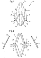
- Figur 1 eine erste Ausführungsform des erfindungsgemäßen Luftkanals in vereinfachter Darstellung;
- Figur 2 die wesentlichen Komponenten des Luftkanals aus Figur 1;
- Figur 3 eine vergrößerte Darstellung des Details X aus Figur 2; und
- Figur 4 eine zweite Ausführungsform des erfindungsgemäßen Luftkanals.
- Figure 1 shows a first embodiment of the air duct according to the invention in a simplified representation;
- Figure 2 shows the essential components of the air duct of Figure 1;
- Figure 3 is an enlarged view of the detail X of Figure 2; and
- Figure 4 shows a second embodiment of the air duct according to the invention.
Die in den Figuren 1 und 2 sehr vereinfacht dargestellte erste Ausführungsform 10 des erfindungsgemäßen Luftkanals besteht im wesentlichen aus einem unteren Wandungsteil 12 und einem oberen Wandungsteil 14, die zusammen eine einen Kanal 16 umgebende Wandung bilden, sowie einer Dichtung in Form von zwei Dichtungsleisten 18, 20. Das untere Wandungsteil 12 ist aus einem vergleichsweise harten Kunststoff, z.B. PP, das obere Wandungsteil 14 aus einem vergleichsweise weichen Kunststoff, z.B. PE-LD, gebildet. Wie in der Detailansicht der Figur 3 zu erkennen ist, weist eines der Wandungsteile Rastnasen 22 auf, die in passende Rastaufnahmen 24 des anderen Wandungsteils eingreifen. Die dadurch gebildeten Rastverbindungen erleichtern die Handhabung bei der weiter unten noch genauer beschriebenen Fertigung des Luftkanals 10.The
Wie aus Figur 2 hervorgeht, weisen beide Wandungsteile 12, 14 seitliche Flansche 26, 28 bzw. 30, 32 mit Nuten 34, 36 bzw. 38, 40 auf, in die die Dichtungsteile 18, 20 eingefügt sind. Die Dichtungsteile 18, 20 erstrecken sich im wesentlichen über die gesamte Länge des Luftkanals 10 und weisen mehrere kegelförmige Vorsprünge 42 auf, die in entsprechende Ausnehmungen 44 der Flansche 26, 28, 30, 32 eingreifen. Die Vorsprünge 42 dienen insbesondere zur relativen Fixierung der beiden Wandungsteile 12, 14.As is apparent from Figure 2, both
Die Herstellung des Luftkanals 10 erfolgt in einem Mehrkomponenten-Spritzgußverfahren. Zunächst werden die beiden Wandungsteile 12, 14 in entsprechenden Formwerkzeugkavitäten aus unterschiedlich hartem Kunststoff gespritzt. Die beiden Wandungsteile 12, 14 werden dann miteinander verrastet und als lose verbundene Einheit in eine weitere Kavität eingesetzt. Nun werden die Dichtungsleisten 18, 20 in die Nuten 34, 36, 38, 40 eingespritzt, wobei auch Dichtmaterial in die Ausnehmungen 44 der Flansche 26, 28, 30, 32 gepreßt wird. Auf diese Weise entstehen die als Fixierhilfe dienenden kegelförmigen Vorsprünge 42.The production of the
Die gespritzte Dichtung hat nicht nur eine Dichtfunktion, sondern sorgt auch für die endgültige Befestigung der beiden Wandungsteile 12, 14 aneinander.The sprayed seal not only has a sealing function, but also ensures the final attachment of the two
Die Herstellung des Luftkanals 10 kann alternativ in einem Einkomponentenverfahren erfolgen. Der Ablauf des Einkomponentenverfahrens unterscheidet sich nicht wesentlich vom Mehrkomponentenverfahren.The production of the
Der fertige Luftkanal 10 wird so in den Motorraum eines Kraftfahrzeugs eingebaut, daß das härtere untere Wandungsteil 12 der Motorhaube des Kraftfahrzeugs abgewandt und das weichere obere Wandungsteil 14 der Motorhaube zugewandt ist. Die Befestigung des Luftkanals 10 im Motorraum erfolgt über das stabilere, untere Wandungsteil 12.The finished
In Figur 4 ist eine weitere Ausführungsform 10' des erfindungsgemäßen Luftkanals mit einem unteren Wandungsteil 12' und einem oberen Wandungsteil 14' gezeigt. Auch bei dieser Ausführungsform ist das untere Wandungsteil 12' aus einem vergleichsweise harten Kunststoff und das obere Wandungsteil 14' aus einem vergleichsweise weichen Kunststoff gebildet.FIG. 4 shows a further embodiment 10 'of the air duct according to the invention with a lower wall part 12' and an upper wall part 14 '. Also in this embodiment, the lower wall portion 12 'of a comparatively hard plastic and the upper wall portion 14' is formed of a relatively soft plastic.
Der wesentliche Unterschied zur ersten Ausführungsform besteht darin, daß die Dichtungsleisten, von denen in Figur 4 nur eine Leiste 18' zu sehen ist, nicht zwischen den Flanschen der Wandungsteile 12', 14' angeordnet sind, sondern die Flansche außen umgreifen. Außerdem ist die vertikale Höhe des weicheren oberen Wandungsteils 14' deutlich größer als die des harten unteren Wandungsteils 12'.The essential difference from the first embodiment is that the sealing strips, of which only one strip 18 'can be seen in FIG. 4, are not arranged between the flanges of the wall parts 12', 14 ', but embrace the flanges on the outside. In addition, the vertical height of the softer upper wall portion 14 'is significantly greater than that of the hard lower wall portion 12'.
Die Herstellung erfolgt nach dem gleichen Prinzip wie bei der ersten Ausführungsform.The production takes place according to the same principle as in the first embodiment.
Claims (14)
Applications Claiming Priority (1)
| Application Number | Priority Date | Filing Date | Title |
|---|---|---|---|
| DE200610021386 DE102006021386A1 (en) | 2006-05-08 | 2006-05-08 | Air duct for a motor vehicle |
Publications (2)
| Publication Number | Publication Date |
|---|---|
| EP1854681A2 true EP1854681A2 (en) | 2007-11-14 |
| EP1854681A3 EP1854681A3 (en) | 2008-11-05 |
Family
ID=38337677
Family Applications (1)
| Application Number | Title | Priority Date | Filing Date |
|---|---|---|---|
| EP20070009143 Withdrawn EP1854681A3 (en) | 2006-05-08 | 2007-05-07 | Air duct for motor vehicle |
Country Status (2)
| Country | Link |
|---|---|
| EP (1) | EP1854681A3 (en) |
| DE (1) | DE102006021386A1 (en) |
Cited By (5)
| Publication number | Priority date | Publication date | Assignee | Title |
|---|---|---|---|---|
| WO2013144480A1 (en) * | 2012-03-27 | 2013-10-03 | Peugeot Citroen Automobiles Sa | Cabin air supply duct |
| FR3017569A3 (en) * | 2014-02-14 | 2015-08-21 | Renault Sa | DEFORMABLE AIR CONDUIT |
| WO2015150657A1 (en) * | 2014-04-03 | 2015-10-08 | Renault S.A.S | Motor vehicle comprising a partly flexible turbocompressor air outlet duct |
| DE102018109710A1 (en) | 2018-04-23 | 2019-10-24 | Dr. Ing. H.C. F. Porsche Aktiengesellschaft | Multi-part air duct in a motor vehicle and method for producing such an air duct |
| US10710427B2 (en) * | 2018-10-08 | 2020-07-14 | Thor Tech, Inc. | High flow rate ductwork for a recreational vehicle |
Families Citing this family (3)
| Publication number | Priority date | Publication date | Assignee | Title |
|---|---|---|---|---|
| DE102014010836B4 (en) * | 2014-07-24 | 2018-12-27 | Mann+Hummel Gmbh | Fluid pipe of a fluid line of a motor vehicle, motor vehicle and internal combustion engine with at least one fluid pipe |
| JP7152887B2 (en) * | 2018-07-03 | 2022-10-13 | 株式会社イノアックコーポレーション | duct |
| DE102019206852A1 (en) | 2019-05-10 | 2020-11-12 | Volkswagen Aktiengesellschaft | Air duct device and motor vehicle |
Citations (5)
| Publication number | Priority date | Publication date | Assignee | Title |
|---|---|---|---|---|
| US20040169401A1 (en) * | 2001-04-27 | 2004-09-02 | Jean-Michel Laborie | Structuring air duct |
| US20050225121A1 (en) * | 2004-04-12 | 2005-10-13 | Lear Corporation | Air duct assembly |
| US6973724B1 (en) * | 1999-07-23 | 2005-12-13 | Valeo | Method for making a tubular element and resulting tubular element |
| US20060040605A1 (en) * | 2004-08-17 | 2006-02-23 | Hyundai Mobis Co., Ltd. | Instrument panel integrated defroster duct |
| EP1810855A1 (en) * | 2006-01-18 | 2007-07-25 | Behr GmbH & Co. KG | Air outlet, in particular for a vehicle ventilation system |
Family Cites Families (9)
| Publication number | Priority date | Publication date | Assignee | Title |
|---|---|---|---|---|
| DE29611394U1 (en) * | 1996-07-01 | 1996-08-14 | Volkswagen Ag, 38440 Wolfsburg | Flow channel for an air duct system |
| DE10257072A1 (en) * | 2002-12-06 | 2004-06-24 | Mann + Hummel Gmbh | Component for installation at a short distance under the outer body skin of a motor vehicle in the pedestrian impact area |
| JP4117548B2 (en) * | 2003-01-30 | 2008-07-16 | 株式会社イノアックコーポレーション | Duct for vehicle |
| JP4243713B2 (en) * | 2003-03-18 | 2009-03-25 | 株式会社イノアックコーポレーション | Duct for vehicle |
| US20070006986A1 (en) * | 2003-10-08 | 2007-01-11 | Martin Derleth | Component, especially a hybid carrier for a vehicle, and method for the production of said type of component, and use of said type of component |
| DE102004007283A1 (en) * | 2004-02-14 | 2005-09-01 | Daimlerchrysler Ag | Housing for air conditioning system in vehicle has a crush construction to minimise injury to persons especially pedestrians falling onto the engine cover |
| DE102004032597A1 (en) * | 2004-07-06 | 2006-02-16 | Volkswagen Ag | bonnet |
| JP4581612B2 (en) * | 2004-10-08 | 2010-11-17 | マツダ株式会社 | Support structure for intercooler cooling duct of vehicle |
| DE102004054274A1 (en) * | 2004-11-09 | 2006-05-11 | Mann + Hummel Gmbh | Intake system for the internal combustion engine of a vehicle |
-
2006
- 2006-05-08 DE DE200610021386 patent/DE102006021386A1/en not_active Withdrawn
-
2007
- 2007-05-07 EP EP20070009143 patent/EP1854681A3/en not_active Withdrawn
Patent Citations (5)
| Publication number | Priority date | Publication date | Assignee | Title |
|---|---|---|---|---|
| US6973724B1 (en) * | 1999-07-23 | 2005-12-13 | Valeo | Method for making a tubular element and resulting tubular element |
| US20040169401A1 (en) * | 2001-04-27 | 2004-09-02 | Jean-Michel Laborie | Structuring air duct |
| US20050225121A1 (en) * | 2004-04-12 | 2005-10-13 | Lear Corporation | Air duct assembly |
| US20060040605A1 (en) * | 2004-08-17 | 2006-02-23 | Hyundai Mobis Co., Ltd. | Instrument panel integrated defroster duct |
| EP1810855A1 (en) * | 2006-01-18 | 2007-07-25 | Behr GmbH & Co. KG | Air outlet, in particular for a vehicle ventilation system |
Cited By (9)
| Publication number | Priority date | Publication date | Assignee | Title |
|---|---|---|---|---|
| WO2013144480A1 (en) * | 2012-03-27 | 2013-10-03 | Peugeot Citroen Automobiles Sa | Cabin air supply duct |
| FR2988648A1 (en) * | 2012-03-27 | 2013-10-04 | Peugeot Citroen Automobiles Sa | CONDUIT OF CAR AIR SUPPLY |
| FR3017569A3 (en) * | 2014-02-14 | 2015-08-21 | Renault Sa | DEFORMABLE AIR CONDUIT |
| WO2015150657A1 (en) * | 2014-04-03 | 2015-10-08 | Renault S.A.S | Motor vehicle comprising a partly flexible turbocompressor air outlet duct |
| FR3019511A1 (en) * | 2014-04-03 | 2015-10-09 | Renault Sa | "AUTOMOTIVE VEHICLE COMPRISING A SOFT PARTLY TURBOCHARGER AIR OUTPUT DUCT" |
| DE102018109710A1 (en) | 2018-04-23 | 2019-10-24 | Dr. Ing. H.C. F. Porsche Aktiengesellschaft | Multi-part air duct in a motor vehicle and method for producing such an air duct |
| DE102018109710B4 (en) | 2018-04-23 | 2022-10-20 | Dr. Ing. H.C. F. Porsche Aktiengesellschaft | Multi-part air duct in a motor vehicle and method for producing such an air duct |
| US10710427B2 (en) * | 2018-10-08 | 2020-07-14 | Thor Tech, Inc. | High flow rate ductwork for a recreational vehicle |
| US11318810B2 (en) | 2018-10-08 | 2022-05-03 | Thor Tech, Inc. | High flow rate ductwork for a recreational vehicle |
Also Published As
| Publication number | Publication date |
|---|---|
| EP1854681A3 (en) | 2008-11-05 |
| DE102006021386A1 (en) | 2007-11-15 |
Similar Documents
| Publication | Publication Date | Title |
|---|---|---|
| EP1854681A2 (en) | Air duct for motor vehicle | |
| DE19926997C2 (en) | Pressure relief valve and method for its production | |
| EP2000277B1 (en) | Venting device for a motor vehicle and method and moulding tool for manufacturing of venting device | |
| DE69910175T2 (en) | SOUNDPROOF MAT WITH SHAPED FASTENING ELEMENT | |
| DE10117278A1 (en) | Plastic molding for use in a vehicle and method of manufacturing the same | |
| WO2016198217A1 (en) | Profiled strip, system and method for producing a profiled strip | |
| DE112006002513T5 (en) | Interior interior part of a work vehicle and method of manufacturing the same | |
| DE102007062758A1 (en) | Molding process, molded product and instrument panel | |
| DE102004062331B4 (en) | Heat shield and method for its production | |
| DE102018213487A1 (en) | Hybrid component and method for producing a hybrid component | |
| DE102010025137A1 (en) | Polyurethane-mold parts manufacturing method for use in interior components of vehicle, involves foaming lightweight core with compact load-bearing polyurethane system for enabling cohesive connection with material of fixing pins | |
| DE10334273A1 (en) | Method for producing a sound insulating compound element, in particular, for motor vehicles involves joint compression of a heavy plasticized material and an open-pore elastic absorber material | |
| DE102006058546A1 (en) | Airbag flap manufacturing method for passenger seat of vehicle, involves bending upward and downward shafts, which are formed at lower surface of airbag flap, in accordance with assembly angle of airbag module | |
| EP1298034B1 (en) | Roof part , especially internal lining for a vehicle roof , and method of its production | |
| DE102015114238A1 (en) | Connection system and method for attaching a component to a vehicle body | |
| DE2826258A1 (en) | METHOD OF MANUFACTURING A SUN VISOR | |
| WO2005016624A1 (en) | Hybrid component and associated production method | |
| EP2563620B1 (en) | Vehicle interior trim part and method for producing a vehicle interior trim part | |
| DE19752786A1 (en) | Inbuilt glove box compartment, having soft interior surface and harder exterior | |
| EP2756975B1 (en) | Lamella, method for mounting a lamella, injection mould and method for producing a component of a lamella | |
| DE102011084498A1 (en) | Method for producing a frame for an engine cooling fan of a motor vehicle | |
| DE102009005993A1 (en) | Airbag module and method for its production | |
| DE10052003B4 (en) | Ventilation flap assembly for motor vehicles, method for producing such ventilation flap assemblies and mold for performing such a method | |
| WO2008119706A1 (en) | Method for the production of a sealing assembly, in particular for a motor vehicle, having a sealing element and a support, and such a sealing assembly | |
| DE102021111776A1 (en) | BLIND MOUNTING FASTENING SYSTEM |
Legal Events
| Date | Code | Title | Description |
|---|---|---|---|
| PUAI | Public reference made under article 153(3) epc to a published international application that has entered the european phase |
Free format text: ORIGINAL CODE: 0009012 |
|
| AK | Designated contracting states |
Kind code of ref document: A2 Designated state(s): AT BE BG CH CY CZ DE DK EE ES FI FR GB GR HU IE IS IT LI LT LU LV MC MT NL PL PT RO SE SI SK TR |
|
| AX | Request for extension of the european patent |
Extension state: AL BA HR MK YU |
|
| RAP1 | Party data changed (applicant data changed or rights of an application transferred) |
Owner name: TRW AUTOMOTIVE ELECTRONICS & COMPONENTS GMBH |
|
| PUAL | Search report despatched |
Free format text: ORIGINAL CODE: 0009013 |
|
| AK | Designated contracting states |
Kind code of ref document: A3 Designated state(s): AT BE BG CH CY CZ DE DK EE ES FI FR GB GR HU IE IS IT LI LT LU LV MC MT NL PL PT RO SE SI SK TR |
|
| AX | Request for extension of the european patent |
Extension state: AL BA HR MK RS |
|
| 17P | Request for examination filed |
Effective date: 20090408 |
|
| AKX | Designation fees paid |
Designated state(s): AT BE BG CH CY CZ DE DK EE ES FI FR GB GR HU IE IS IT LI LT LU LV MC MT NL PL PT RO SE SI SK TR |
|
| 17Q | First examination report despatched |
Effective date: 20100324 |
|
| STAA | Information on the status of an ep patent application or granted ep patent |
Free format text: STATUS: THE APPLICATION IS DEEMED TO BE WITHDRAWN |
|
| 18D | Application deemed to be withdrawn |
Effective date: 20111005 |