EP2563261B1 - Robotervorrichtung für minimal invasive chirurgie - Google Patents
Robotervorrichtung für minimal invasive chirurgie Download PDFInfo
- Publication number
- EP2563261B1 EP2563261B1 EP11723661.2A EP11723661A EP2563261B1 EP 2563261 B1 EP2563261 B1 EP 2563261B1 EP 11723661 A EP11723661 A EP 11723661A EP 2563261 B1 EP2563261 B1 EP 2563261B1
- Authority
- EP
- European Patent Office
- Prior art keywords
- arm
- robotic arm
- proximal
- introducer body
- robotic
- Prior art date
- Legal status (The legal status is an assumption and is not a legal conclusion. Google has not performed a legal analysis and makes no representation as to the accuracy of the status listed.)
- Not-in-force
Links
- 238000002324 minimally invasive surgery Methods 0.000 title claims description 5
- 210000001503 joint Anatomy 0.000 claims description 73
- 230000033001 locomotion Effects 0.000 claims description 38
- 230000005540 biological transmission Effects 0.000 claims description 33
- 230000007246 mechanism Effects 0.000 claims description 32
- 238000002357 laparoscopic surgery Methods 0.000 claims description 13
- 238000000034 method Methods 0.000 description 27
- 238000003780 insertion Methods 0.000 description 20
- 230000037431 insertion Effects 0.000 description 20
- 238000001356 surgical procedure Methods 0.000 description 18
- 230000008901 benefit Effects 0.000 description 8
- 238000013459 approach Methods 0.000 description 6
- 230000008878 coupling Effects 0.000 description 6
- 238000010168 coupling process Methods 0.000 description 6
- 238000005859 coupling reaction Methods 0.000 description 6
- 210000000683 abdominal cavity Anatomy 0.000 description 5
- 210000000245 forearm Anatomy 0.000 description 5
- 230000009467 reduction Effects 0.000 description 4
- 230000003187 abdominal effect Effects 0.000 description 3
- 239000012636 effector Substances 0.000 description 3
- 230000008447 perception Effects 0.000 description 3
- 238000012084 abdominal surgery Methods 0.000 description 2
- 229940030225 antihemorrhagics Drugs 0.000 description 2
- 230000000295 complement effect Effects 0.000 description 2
- 230000000694 effects Effects 0.000 description 2
- 239000012530 fluid Substances 0.000 description 2
- 230000000025 haemostatic effect Effects 0.000 description 2
- 230000014759 maintenance of location Effects 0.000 description 2
- 230000009347 mechanical transmission Effects 0.000 description 2
- 210000000707 wrist Anatomy 0.000 description 2
- 208000032544 Cicatrix Diseases 0.000 description 1
- 241000270923 Hesperostipa comata Species 0.000 description 1
- 208000008589 Obesity Diseases 0.000 description 1
- 235000019892 Stellar Nutrition 0.000 description 1
- 210000001015 abdomen Anatomy 0.000 description 1
- 230000001154 acute effect Effects 0.000 description 1
- 239000000853 adhesive Substances 0.000 description 1
- 230000001070 adhesive effect Effects 0.000 description 1
- 238000004873 anchoring Methods 0.000 description 1
- 230000000712 assembly Effects 0.000 description 1
- 238000000429 assembly Methods 0.000 description 1
- 238000007681 bariatric surgery Methods 0.000 description 1
- 210000000746 body region Anatomy 0.000 description 1
- 230000008859 change Effects 0.000 description 1
- 238000002192 cholecystectomy Methods 0.000 description 1
- 230000006835 compression Effects 0.000 description 1
- 238000007906 compression Methods 0.000 description 1
- 238000010276 construction Methods 0.000 description 1
- 230000001419 dependent effect Effects 0.000 description 1
- 210000002310 elbow joint Anatomy 0.000 description 1
- 238000005516 engineering process Methods 0.000 description 1
- 230000006870 function Effects 0.000 description 1
- 210000004247 hand Anatomy 0.000 description 1
- 230000003116 impacting effect Effects 0.000 description 1
- 230000006872 improvement Effects 0.000 description 1
- 208000015181 infectious disease Diseases 0.000 description 1
- 230000001404 mediated effect Effects 0.000 description 1
- 235000020824 obesity Nutrition 0.000 description 1
- 230000001575 pathological effect Effects 0.000 description 1
- 230000036316 preload Effects 0.000 description 1
- 238000011084 recovery Methods 0.000 description 1
- 238000011160 research Methods 0.000 description 1
- 230000000452 restraining effect Effects 0.000 description 1
- 238000002432 robotic surgery Methods 0.000 description 1
- 231100000241 scar Toxicity 0.000 description 1
- 230000037387 scars Effects 0.000 description 1
- 238000013519 translation Methods 0.000 description 1
- 238000010396 two-hybrid screening Methods 0.000 description 1
Images




Classifications
-
- A—HUMAN NECESSITIES
- A61—MEDICAL OR VETERINARY SCIENCE; HYGIENE
- A61B—DIAGNOSIS; SURGERY; IDENTIFICATION
- A61B34/00—Computer-aided surgery; Manipulators or robots specially adapted for use in surgery
- A61B34/30—Surgical robots
-
- A—HUMAN NECESSITIES
- A61—MEDICAL OR VETERINARY SCIENCE; HYGIENE
- A61B—DIAGNOSIS; SURGERY; IDENTIFICATION
- A61B1/00—Instruments for performing medical examinations of the interior of cavities or tubes of the body by visual or photographical inspection, e.g. endoscopes; Illuminating arrangements therefor
- A61B1/313—Instruments for performing medical examinations of the interior of cavities or tubes of the body by visual or photographical inspection, e.g. endoscopes; Illuminating arrangements therefor for introducing through surgical openings, e.g. laparoscopes
-
- A—HUMAN NECESSITIES
- A61—MEDICAL OR VETERINARY SCIENCE; HYGIENE
- A61B—DIAGNOSIS; SURGERY; IDENTIFICATION
- A61B17/00—Surgical instruments, devices or methods
-
- B—PERFORMING OPERATIONS; TRANSPORTING
- B25—HAND TOOLS; PORTABLE POWER-DRIVEN TOOLS; MANIPULATORS
- B25J—MANIPULATORS; CHAMBERS PROVIDED WITH MANIPULATION DEVICES
- B25J18/00—Arms
-
- A—HUMAN NECESSITIES
- A61—MEDICAL OR VETERINARY SCIENCE; HYGIENE
- A61B—DIAGNOSIS; SURGERY; IDENTIFICATION
- A61B17/00—Surgical instruments, devices or methods
- A61B17/28—Surgical forceps
- A61B17/29—Forceps for use in minimally invasive surgery
- A61B2017/2901—Details of shaft
- A61B2017/2906—Multiple forceps
-
- A—HUMAN NECESSITIES
- A61—MEDICAL OR VETERINARY SCIENCE; HYGIENE
- A61B—DIAGNOSIS; SURGERY; IDENTIFICATION
- A61B34/00—Computer-aided surgery; Manipulators or robots specially adapted for use in surgery
- A61B34/30—Surgical robots
- A61B2034/305—Details of wrist mechanisms at distal ends of robotic arms
-
- Y—GENERAL TAGGING OF NEW TECHNOLOGICAL DEVELOPMENTS; GENERAL TAGGING OF CROSS-SECTIONAL TECHNOLOGIES SPANNING OVER SEVERAL SECTIONS OF THE IPC; TECHNICAL SUBJECTS COVERED BY FORMER USPC CROSS-REFERENCE ART COLLECTIONS [XRACs] AND DIGESTS
- Y10—TECHNICAL SUBJECTS COVERED BY FORMER USPC
- Y10T—TECHNICAL SUBJECTS COVERED BY FORMER US CLASSIFICATION
- Y10T74/00—Machine element or mechanism
- Y10T74/19—Gearing
- Y10T74/1987—Rotary bodies
- Y10T74/19893—Sectional
- Y10T74/19907—Sound deadening
-
- Y—GENERAL TAGGING OF NEW TECHNOLOGICAL DEVELOPMENTS; GENERAL TAGGING OF CROSS-SECTIONAL TECHNOLOGIES SPANNING OVER SEVERAL SECTIONS OF THE IPC; TECHNICAL SUBJECTS COVERED BY FORMER USPC CROSS-REFERENCE ART COLLECTIONS [XRACs] AND DIGESTS
- Y10—TECHNICAL SUBJECTS COVERED BY FORMER USPC
- Y10T—TECHNICAL SUBJECTS COVERED BY FORMER US CLASSIFICATION
- Y10T74/00—Machine element or mechanism
- Y10T74/20—Control lever and linkage systems
- Y10T74/20207—Multiple controlling elements for single controlled element
- Y10T74/20305—Robotic arm
-
- Y—GENERAL TAGGING OF NEW TECHNOLOGICAL DEVELOPMENTS; GENERAL TAGGING OF CROSS-SECTIONAL TECHNOLOGIES SPANNING OVER SEVERAL SECTIONS OF THE IPC; TECHNICAL SUBJECTS COVERED BY FORMER USPC CROSS-REFERENCE ART COLLECTIONS [XRACs] AND DIGESTS
- Y10—TECHNICAL SUBJECTS COVERED BY FORMER USPC
- Y10T—TECHNICAL SUBJECTS COVERED BY FORMER US CLASSIFICATION
- Y10T74/00—Machine element or mechanism
- Y10T74/20—Control lever and linkage systems
- Y10T74/20207—Multiple controlling elements for single controlled element
- Y10T74/20305—Robotic arm
- Y10T74/20329—Joint between elements
- Y10T74/20335—Wrist
Definitions
- the present invention refers to a robotic apparatus for minimally invasive surgery (hereinafter referred to as mini-invasive for the sake of simplicity), in particular laparoscopic surgery.
- surgeon In the conventional surgery procedures, or open surgery, the surgeon generally performs a very long incision. After this, the surgeon intervenes on the part of interest manually or using manually actuated instruments. Thus, the surgeon has the following advantages:
- the robot should pass through natural lumen or through a single access port, the dimensions thereof should necessarily be minimum thus implying the use of motors of smaller dimensions and consequently having low power. Therefore, the NOTES approach is not capable of guaranteeing the performance of the Da Vinci system in terms of motion speed of the instrument and tractive force.
- the latter aspect is also related to the lack of a stable rigid support for the operating arms capable of allowing exerting considerable amounts of force into the manipulation for surgery tasks.
- US patent application No. US 2008/0110958 discloses a surgical stapling device for clamping and stapling tissues and for dispensing a fluid, such as an adhesive, onto the tissue during surgical procedures.
- This device is provided with a differential system which allows only a rotational movement of the joints that are connected to the gear system.
- the known systems do not achieve an optimal compromise among dexterity, power and degrees of freedom on one hand and mini-invasiveness (also with the possibility of a single access port) on the other.
- the systems that allow operating in minimum invasiveness conditions with a single access port or through a natural orifice do not allow achieving the stability and power required for abdominal surgery.
- one of the problems associated to the abovementioned drawbacks is that of obtaining a satisfactory rigidity of the kinematic chain of the robotic arms actuable from outside and a reduction of the relative mechanical clearances, and at the same time providing an effective on board actuation of the distal joints of the robotic arm.
- the technical drawback addressed and resolved by the present invention is to provide a robotic apparatus for laparoscopic operations capable of allowing overcoming the previously mentioned drawbacks with reference to the prior art.
- the present invention provides some relevant advantages.
- the main advantage lies in the fact that it provides a differential mechanism which is particularly efficient and small in size, suited for the transmission of motion in any miniaturized system which receives or is adapted to receive means for driving a flexural joint and a torsional joint serially arranged, given that it can be interposed between such drive means and said joints.
- a robotic apparatus for laparoscopic surgery is indicated in its entirety with 100.
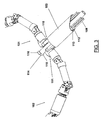
- the apparatus 100 is represented in an exemplifying configuration which provides for a first and a second robotic arm, respectively indicated with 101 and 102, each having a plurality of articulated joints arranged longitudinally along the arm according to a serial structure.
- each arm 101, 102 has six degrees of freedom.
- the distal end portion (with respect to the surgeon) of each robotic arm 101, 102 may be equipped with surgical instruments, such as for example forceps 109, or with sensors, such as cameras or biometric sensors.
- the apparatus comprises a serial arm 101 and two hybrid parallel/serial structure arms respectively indicated with 201 and 202.
- the apparatus 100 also comprises a support body 103, or introducer, having a cylindrical-shaped tubular structure in its entirety analogous to and compatible with that of a trochar.
- the support body 103 has a symmetrical longitudinal axis indicated with X in Figure 1 .
- the support body 103 is thus adapted to serve as an introducer for the arms 101 and 102 into the body of the patient, allowing the passage of both through it.
- the apparatus 100 further comprises a stereoscopic vision system 104, schematically represented in Figure 1 .
- a stereoscopic vision system 104 may be associated to one of the arms 101 or 102 or introduced through the support body 103 with other means.
- the introducer body 103 is conceived to allow the introduction of the robotic arms of the apparatus 100 into the body of the patient.
- FIGS. 2A to 2I thus show, schematically and in sequence, how each of the robotic arms 101 and 102 is inserted, during a laparoscopic surgery, through the introducer body 103.
- the first arm 101 is arranged longitudinally in the introducer body 103 in a rectilinear alignment configuration of the joints thereof.
- such engaging means comprise a longitudinal face 112 projecting from a first basic proximal portion 110 of the arm 101 and adapted to slide in a respective groove 113 provided in the inner wall of the support body 103.
- proximal joints of the arm 101 are actuated (according to the methods to be described hereinafter) so as to allow a substantially 90 degrees rotation of the most proximal joint outwards relative to the longitudinal axis of the introducer body 103.
- the second arm 102 is thus introduced, according to methods similar to those described above regarding the first arm.
- each robotic arm 101, 102 has a first basic proximal portion 110 adapted to be slidably coupled with the inner wall of the introducer body 103.
- each robotic arm 101, 102 has a second proximal portion 111, arranged distally with respect to the first proximal portion and associated to the abovementioned plurality of articulated joints and in turn articulated to the basic portion 110 so as to be able to rotate by about 90 degrees with respect to the latter, i.e. with respect to the longitudinal axis X of the introducer body 103.
- Such "folding" of the arm may be either passive or externally actuated, for example through cable actuation systems or other mechanical transmission means of per se known type.
- each arm is formed with a locking seat 117, better observable in Figure 5A and whose role will be clarified shortly.
- the overall structure of the apparatus 100 is such that both arms 101 and 102 can be simultaneously inserted through the introducer body 103 and housed, during use, therein at the basic proximal portion 110 thereof.
- transmission cables 108 intended to transmit motion to the most proximal joints (shoulder) of the arms 101 and 102 were represented purely by way of example; their role shall be explained hereinafter.
- the apparatus 100 also comprises a locking element 114, or pin, which is adapted to be inserted longitudinally through the introducer body 103 centrally between the two arms 101 and 102 for locking the latter on the introducer body.
- the locking element 114 bears, at the longitudinal end thereof arranged distally during use, two transverse shaped projections, respectively indicated with 115 and 116, arranged on diametrically opposite sides and each adapted to be inserted in a respective locking seat 117 of a respective arm 101, 102.
- the locking element 114 has a tubular structure, i.e. a longitudinal interior lumen, indicated with 118 in Figure 5A .
- the locking element 114 is introduced between the two arms, at an arrangement in which the projections 115, 116 are orthogonal to the transverse direction of extension of the second proximal portions 111.
- the locking element 114 once entirely introduced through the body 103, is rotated so as to couple such projections 115, 116 within the respective seats 117, where they are fittingly restrained, snap restrained or restrained through other means analogous retention means.
- the locking element 114 integral with the introducer body 103, the most proximal part of each arm 101, 102 is firmly locked on the introducer body 103.
- the locking element 114 may be connected to an external rigid support, for example a motor which makes it slide and rotate by 90°.
- the previously described locking means allow locking the arms firmly in position after introduction thereof, providing a considerable mechanical stability thereto.
- the arms form a single body with the introducer body 103.
- the central locking element 114 contributes to stiffening the assembly.
- the described arrangement allows obtaining a stable support for the operating arms though operating through a single lumen (for example the belly-button) or access port.
- a single lumen for example the belly-button
- the robotic arms can exert considerable amounts of forces and thus be capable of performing any manipulating task required for surgery purposes.
- the apparatus of the invention may exert considerable forces and obtain a satisfactory dexterity.
- the apparatus obtains an effective bimanuality though it can operate through a single lumen or access port.
- FIGS. 5A and 5B also show how two lateral lumens 119 and 120 in the introducer body 103 remain available with locking completed.
- the described arrangement guarantees a safe removal of the lock.
- the locking element 114 is made rigid and it can be manoeuvred from outside, the risks related to the impossibility of folding the arms after completing the operation are minimum.
- Figure 6 shows a variation of the previously described locking means, in which the overall construction - and in particular the arrangement of the projections 115, 116 and of the relative seats 117 - is not axial-symmetric.
- the overall arrangement is such that, once locked on the introducer body 103, the second proximal portions 111 of the two arms 101 and 102 have incident longitudinal axes according to an acute angle ⁇ . which is also the relative angle according to which the two projections 115, 116 and obviously the respective seats 117 are arranged.
- the serial structure arm 101 has six degrees of freedom, associated to an equivalent number of rotary joints and preferably distributed as follows:
- the mobility and final dexterity of the arm 101 are obtained with an alternation of torsional and flexural joints arranged longitudinally in sequence along the arm.
- a further opening/closing degree of freedom can be obtained at the level of the distal instrument 109, as schematically shown with an arrow in Figure 7 .
- the first two joints 1, 2 will be defined “proximal” and the other four joints 3-6 will be defined “distal” for the sake of simplicity.
- the first two joints 1 and 2 can be intended as associated to the degrees of freedom of a shoulder, the third joint 3 intended as associated to a degree of freedom for folding an elbow and the last three joints 4-6 intended as associated to the three degrees of freedom of a spherical wrist arranged at a "forearm”.
- the first two proximal joints 1-2 are actuated from outside through special transmission means, while the other four joints are actuated through local motor means.
- Figures 8A and 8B refer to a preferred embodiment of means for transmitting motion from external actuators 80 and 90 (schematically represented in Figure 8A and per se known) to the proximal joints 1 and 2.
- the transmission means are based on a bevel gear.
- the two external actuators 80 and 90 are each connected to a respective first or second rotating drive shaft 8, 9 arranged at the beginning of the kinematic chain of the arm.
- Each drive shaft 8, 9 is housed in a respective first or second sleeve 11, 12, in turn made integral with the introducer body 103 after insertion into the latter.
- Such fastening of the sleeves 11, 12 to the introducer body 103 can be obtained through known fastening means applied between the drive body 80, 90 and the introducer body 103.
- Each drive shaft 8, 9 traverses an external casing portion of the arm 101, indicated with 10 and associated to the two joints 1 and 2, and it is removably coupled thereto through roller bearings or equivalent connection means.
- the casing portion 10 is also integrally joined to the two sleeves 11 and 12.
- the base of the robotic arm 101 at an operating position, is rigidly and integrally anchored to the introducer body 103. Therefore, in this embodiment a locking different from that described with reference to Figures 3 and 4A-6 is provided for.
- the transmission means described herein also comprise a first and a second bevel gear, respectively 13 and 15, each integrally joined to a respective drive shaft 8, 9.
- the first bevel gear 13 transmits motion to a shaft 14 which is extended along the longitudinal axis Y and which, through a further distal bevel gear 16 coupled with a corresponding further component of the joint 2, provides the motion to the latter.
- the second bevel gear 15 transmits motion to a hollow shaft 151 which provides the movement to the joint 1.
- the longitudinal shaft 14 which rotates within the hollow shaft 151 extends coaxially into the hollow shaft 151. Therefore, the movement of the second drive shaft 9 also causes the movement to the second joint 2.
- An independent movement of the first and second joint 1 and 2 through a suitable combination of the movements of the drive shafts 8 and 9, not described further hereinafter given that they are known to a man skilled in the art, can also be obtained.
- the proposed transmission device (which could be subject to a separate and independent protection) is based on a pair of drive shafts 8, 9 each coupled through bevel gears 13, 15 or equivalent means to a further shaft 14, 151 substantially orthogonal thereto, the shafts of this second pair being substantially orthogonal to the respective drive shafts 8, 9 and also being coaxial with respect to each other.
- Figure 9 shows the apparatus 100, highlighting the relative arrangement of the two arms 101 and 102, particularly regarding the portions of the first two proximal joints 1 and 2 and according to the preferred embodiment thereof described last with reference to Figures 8A and 8B .
- the two arms 101 and 102 can be inserted into the introducer body 103 one at a time.
- each arm is supported by two cables 61 and 62, each connected to a respective sleeve 11, 12.
- the hollow shafts 11 and 12 are also introduced through the introducer body 103 and the two cables 61 and 62 connected to each arm are pulled from outside, together with the whole arm so as to introduce the sleeves 11 and 12 into the respective seats within the casing 10.
- the robotic arms 101, 102 are formed with a first and a second proximal portion, the latter indicated with 121 in this case, which is arranged, during use, substantially orthogonal to the longitudinal axis X of the introducer body 103.
- Second variation for transmitting motion from external actuators to the proximal joints of the serial robotic arm
- the external actuation of the "shoulder" joints 1 and 2 provides for the use of respective translating shafts instead of rotating shafts, as shown in Figure 11 .
- the transmission of motion to each of the joints 1 and 2 is obtained through a respective endless screw-toothed wheel mechanism.
- the transmission means comprise, for each joint, a translating drive shaft 800 which traverses the casing 10 of the arm 101 and has a helical thread 27 at the distal end thereof. Thread 27 is mechanically coupled with a toothed wheel 28 housed within the casing 10 and in turn adapted to transmit motion to the corresponding degree of freedom.
- the transmission means considered in this case also comprise an idler wheel 29, arranged on the opposite side of the translating shaft 800 with respect to the toothed wheel 28.
- Such idler wheel 29 allows bearing the radial stresses on the drive shaft 800, due to the endless screw-toothed wheel coupling, which can be critical especially given the small dimensions of the mechanism.
- the insertion of the drive shaft 800 through the casing 10 and between the wheels 28 and 29 can be carried out through an initial rotation thereof associated to an advancement equivalent to the propeller pitch of the thread 27. This allows introducing the shaft without actuating the corresponding degree of freedom. Subsequently, the translation movement of the shaft 800 will allow controlling the desired rotation of the joints 1 and 2.
- the described transmission mechanism is represented coupled to an inner transmission of the motion obtained through cables 30, where a respective driving pulley 31 of each of them is integral with the respective toothed wheel 28.
- translating shaft transmission means allow obtaining a configuration of the system like that shown in Figure 9 , through an insertion and locking system similar to that described regarding the rotating shaft actuation mechanism and shown in Figures 10A and 10B .
- the proposed solution (which could be subject to a separate and independent protection) is based on the use of a translating shaft for each joint, coupled with the joint through a gear transmission mechanism or equivalent transmission mechanism and associated cable elements or equivalent elements.
- the following is a description of another embodiment of the means for transmitting motion from external actuators to the first three proximal joints 1, 2 and 3 of the arm 101, 102 based on a cable transmission mechanism.
- the abovementioned cable transmission means provide for a particular arrangement of idler pulleys within the casing of the arm with the aim of allowing the cables for actuating the joints 2 and 3 to pass beyond the first torsional joint 1.
- idler pulleys are positioned radially at a different distance from the axis of the torsional joint 1.
- the joints 2 and 3 are actuated through a total of four cables, two for each one of them i.e. for each degree of freedom. As mentioned above, the four cables should pass through the first joint 1 and two of them also through the second joint 2.
- a first cable 17 is passed through a first idler pulley 18 - or first return pulley - positioned on a fixed shaft 19 (i.e. not rotatable with the joint 1) coaxial with the casing of the arm - such main casing/body of the arm is indicated in such case with 22 - and thus with the axis Y of the arm.
- the first pulley 18 is arranged with the rotation axis thereof transverse and thus orthogonal to the axis Y of the fixed shaft 19.
- the cable 17 passes through a second idler pulley 20 - or a second return pulley - positioned on the fixed shaft 19 coaxially with respect thereto.
- the path of the cable 17 proceeds towards a third idler pulley 21 or third return pulley - also arranged with transverse axis orthogonal to the fixed shaft 19 and integral with the external rotating casing 22 of the arm.
- Figures 12 and 13 show further pulleys, besides the ones described, which are suitable for the passage of the other three cables through the joint according to the methods similar to those described above.
- the proposed transmission mechanism can also be associated to the above described embodiment with rotating shafts for actuating the first two joints and used for transmitting motion to the subsequent joints and also to the embodiment with translating shafts also for transmitting motion to the first joints.
- the described mechanism allows actuating cables of several joints downstream of a joint arranged with the axis parallel to the initial longitudinal extension of the cables and in a small space, in that the axis of the idler pulleys is arranged radially relative to the abovementioned joint.
- An idler system like the one described above which in the most general definition thereof is based on a plurality of idler pulleys arranged in sequence and wherein each pulley has an axis orthogonal to that of the adjacent pulley, may actually also be applied even in sectors different from the one considered herein.
- the described arrangement can be applied in any actuator device - even different from the articulated arm portion considered in this case - equipped with a torsional degree of freedom and a flexural degree of freedom.
- such actuator device comprises:
- the abovementioned cable pre-stretching device is adapted to be housed in a small space such as within the proximal part of the arm (i.e. the abovementioned "shoulder").
- the pre-stretching device For each transmission cable, the pre-stretching device provides for the use of two pulleys coupled to each other through a mechanism which allows a unidirectional rotation between the two pulleys.
- a first stretching pulley 23 which is mechanically integral with a shaft 25 and a second stretching pulley 24 free to rotate on the shaft 25 is provided for each cable in Figure 14 .
- the two grooved wheels 26 and 27 are shaped so as to form a mechanical coupling with the shaft 25 which counters a rotation in a direction of the respective pulley, while it leaves the rotation free in the other direction.
- the first wheel 26 has an external saw-toothed profile, which is engaged with a corresponding internal step profile of the second wheel 27, allowing a stepping rotation in one direction (with the teeth sliding on the crests of the steps) and preventing rotation in the opposite direction due to the fact that the teeth abut against the shoulders of the steps.
- the cable can be pre-stretched by rotating the pulley in the free direction of rotation, until the desired preload is reached.
- the counter-rotation of the pulley is hindered by the coupling between the grooved wheels 26 and 27.
- the two or more arms partly actuated by cables can be arranged as shown in Figure 15 according to the general architecture of the apparatus of Figure 1 and with the first method for locking the arms described above.
- each robotic arm 101, 102 of the apparatus 100 of Figure 1 are moved through on-board drive means.
- on-board drive means Such on board actuation is accomplished through miniaturized motors, preferably electrical motors, brushless DC motors in the present example.
- the proposed solution consists in a particular differential mechanism which allows reducing the overall space necessary for housing the two joints 5, 6 and allows housing the motors along the axis of the aforementioned "forearm".
- Such differential mechanism comprises a first and a second assembly of three gear wheels preferably of the conical type, each assembly being respectively indicated with 340 and 350, which are coupled to form the differential by using a train of three further gear wheels preferably straight-cut gear wheels arranged in transverse sequence and respectively indicated with 34 and 35 for the two lateral wheels and with 36 for the central wheel.
- the first assembly of wheels of the conical type 340 comprises three wheels coupled to form a substantially C-shaped structure, and in particular a first and a second wheel 341 and 343 which have incident rotation axes.
- the wheel 341 has a rotation axis parallel to the longitudinal axis of the forearm, while the axis of the wheel 343 rotates around the axis W of a shaft 360, thus forming the degree of freedom 5 of figure 7 .
- a third conical wheel 342 is interposed between the first two for coupling thereof and it is arranged with a rotation axis substantially orthogonal to that of the wheel 341.
- a symmetric arrangement is provided for the second assembly 350.
- the intermediate conical wheels 342 and 352 of the two assemblies are idle on the intermediate shaft 360 of axis W.
- the two lateral wheels 34 and 35 of the aforementioned train of wheels are respectively integral with the first conical wheel 343 of the first assembly 340 and with an analogous first conical wheel 353 of the second assembly 350.
- the central wheel 36 is instead integral with the distal end, indicated with 37, of the robotic arm.
- the conical wheel 341 of the first assembly 340 is instead integral with a drive axis of drive means 38 and a conical wheel 351 of the second assembly 350 is integral with other drive means 39.
- the end of the robotic arm has a so-called pitch (rotation around axis W) and roll (rotation around axis U) degree of rotation depending on whether the drive means 38 and 39 rotate in the same direction of rotation (pitch) or in the opposite direction (roll).
- pitch rotation around axis W
- roll rotation around axis U
- the desired roll and pitch combination can be obtained through a suitable combination of the drive means 38 and 39.
- the joints 4, 5 and 6 thus have incident axes.
- the reduction ratio between the wheels 341 and 342 is greater than 1 and it is equal to the reduction ratio between the wheels 343 and 342. This allows a rotation around the axis w of the shaft 360 greater than 90° without the wheel 343 impacting against the wheel 341.
- differential mechanism described beforehand can also be subject of an independent protection, i.e. independent from the application to a robotic arm.
- differential mechanism is suitable for motion transmission in any system receiving or adapted to receive means for driving a flexural joint and a torsional joint arranged serially, given that it can be interposed between such drive means and said joints.
- the transmission means comprise a first and a second assembly of three gear wheels, preferably of the conical type, and a train of three further gear wheels, preferably straight-cut gear wheels, which couple said first and second assembly to form a differential mechanism.
- the gear wheels of each of the first and second assembly are arranged to form a substantially C-shaped structure, adjacent wheels having mutually orthogonal rotation axes, wherein two wheels have a rotation axis substantially parallel to the axis of the torsional joint and the third intermediate wheel has a rotation axis substantially parallel to or coinciding with the axis of the flexural joint.
- the joint 3 of the so-called "elbow” - which rotates a distal part 41 of the arm (i.e. the forearm) relative to a proximal part 410 - provides for that the rotation shaft 42 extended according to the transverse axis K previously introduced be made as two distinct longitudinal portions 421 and 422.
- the motion is transmitted by a local drive wheel 43 to the axis K of the joint through a coupling of the conical wheels 430 at a right angle associated to the abovementioned two parts 421 and 422 of the shaft 42.
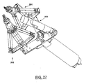
- each of the parallel/serial arms 201, 202 the proximal joints 1-3 of the serial embodiment described above are replaced by a parallel structure 44 which allows a distal part 45 of the arm to have three translational degrees of freedom.
- proximal points actuated by respective drive motors (for example brushless DC motors) positioned outside the apparatus 100, as illustrated further in detail shortly hereinafter.
- proximal articulation points comprise three respective hinges, one of which indicated by way of example with 46. The latter allow the rotation of an equivalent number of corresponding proximal segments 471 with respect to a base 450 of the parallel structure from which each of the proximal segments 471 depart.
- the distal portion 45 translates along three axis orthogonal to each other.
- Each of the proximal segments 471 is then in turn articulated, at a distal end thereof, to a respective distal segment 472, the latter being articulated, at the other end, to the aforementioned distal portion 45.
- the distal portion 45 also has other three rotational degrees of freedom positioned orthogonally with respect to each other, besides the translational ones mentioned above.
- the actuation of the aforementioned three rotational degrees of freedom may either be performed using motors arranged on the distal segments directly or with an equivalent number of motors arranged outside.
- motors arranged outside the power is transmitted to the segments through a cable actuation, the cables sliding along the axes of the parallel structure.
- the actuation of the tool 109 can be transmitted along the arm through a cable and a sheath 48, represented by way of example in the figures considered in this case.
- the combination of the six degrees of freedom allows the tool 109 positioned at the tip to reach the areas the surgeon is operating on, both in terms of position and angle.
- Figure 20 shows - in further detail - the actuation of the articulation points 46 of the present embodiment, in an operative configuration of the robotic arm.
- actuation occurs through motors outside the body of the patient and an associated cable transmission.
- the external motors actuate drive pulleys 49 through respective axes, the pulleys - by means of cables 50 - controlling the degrees of freedom.
- cables 50 are routed into the introducer body 103.
- a series of idler and return pulleys 51 guide the cables 50 towards the opening and coupling mechanisms of the arm and towards the respective joints to be actuated within the robotic arm.
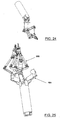
- the robotic arm 201 provides for a first and a second proximal portion, the latter indicated in this case with 131 and which is arranged, during use, substantially orthogonal to the longitudinal axis X of an introducer body 603 which will be described hereinafter.
- an introducer body 603 modified with respect to the one described previously with reference to the serial structure of the arms will be used.
- Such introducer body 603 is inserted into the abdominal cavity of the patient, exemplified with a curved line L in Figures 22A and 22B .
- the introducer body 603 has an operating channel which allows the passage of the surgical arms and the auxiliary instruments. Guides for facilitating the insertion of the surgical arms can be formed on the walls of such operating channel.
- a front incision means 620 whose function is to create an opening for the insertion of the introducer body 603 or facilitate insertion thereof in cases where the opening was already present can be associated, and in particular removably associated, to the introducer body 603 described above.
- the incision means can open to allow the insertion of the arms or be removed directly, as shown in Figure 22C .
- the introducer body also has locking means, intended for reference and rigid positioning of the arms, which are indicated in their entirety with 608 and better shown in Figure 22D .
- locking means 608 comprise a plurality of elongated elements, typically in form of a rod indicated with 609, housed at the inner walls of the introducer body 603 and extended longitudinally parallel to the latter and thus to the longitudinal axis X of the introducer body.
- Each rod 609 bears, at a distal end thereof, a lateral hooking element or projection 610, so as to form a substantially L-shaped configuration of the rod.
- the rods 609 slide along and rotate around a longitudinal axis thereof substantially parallel to the longitudinal axis X of the introducer body, so that the hooking elements 610 can be translated and rotated outwards with respect to the introducer body 603 and not hinder the insertion of the arms through them.
- the element 610 for hooking the corresponding pair can be rotated once again and receded so as to engage them in special seats 611 formed on the proximal portion 131 of the arm, firmly restraining it to the introducer body 603.
- the rods 609 are thus locked on the introducer body 603 after hooking the corresponding arm, so as to complete the retention of said arm on the introducer body 603.
- the introducer body 603 can then be constrained to an external structure capable of orienting and holding it at the desired position.
- an arm 201, 202 can be inserted one at a time, as shown in Figures 23A and 23B .
- the arm 201 has a particular configuration for aligning the relative joints adapted to reduce the overall dimensions and hence facilitate insertion into the introducer body 603, shown in said figure.
- the guides possibly present on the walls of the introducer body facilitate such insertion.
- the substantial difference between the device 103 of Figure 1 and the device 603 considered in this case lies in the fact that the introducer 103 has a common hooking system for all robotic arms. This implies that replacing a robotic arm requires removing all of them. However, it has an advantage lying in the fact that it is easy to construct and hence less expensive and more practical.
- the introducer 603 may replace each arm without necessarily requiring removing the other arms (which can thus continue operating without being influenced by the replacement). This is due to the fact that each robotic arm has its own anchoring system, independent from the others.
- a third arm comprising a vision system 104 is inserted besides the two arms in hybrid configuration.
- the arm dedicated to the vision system not only reveals lesser problems in terms of forces to be transmitted and accuracy of the movements but it can also have a lower number of degrees of freedom with respect to the robotic arms expressly studied for performing surgery.
- a free operating channel is present within the introducer 603 for possibly allowing the use of complementary surgical instruments.
- the configuration described above allows replacing the arms (for example to change the characteristics of the tool) regardless of the presence or absence of other components of the apparatus.
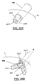
- the introducer body still indicated with 603, further comprises, at the distal end thereof, a structure that can be deployed in a substantially flower-like manner, i.e. three projections 605 rotatably connected on the basic body along the circumference thereof and selectively actuable to pass the introducer body 603 from a minimum overall dimension configuration shown in Figure 26A , wherein such projections are enclosed on the basic body, to a deployed configuration shown in Figure 26B , wherein the projections are rotated outwards.
- This second configuration is adapted to allow the introduction of one or more hybrid arms into the abdominal cavity.
- the hybrid parallel/serial solution for the structure of the robotic arm has the advantage of a greater rigidity of the system, a reduction of the mechanical clearances and the possibility of allowing providing cable actuation more easily.
- the hybrid solution allows providing an actuation system in which one or more motors are positioned outside the robot and the patient in an easier manner. This is due to the fact that taking the power from the motors to the distal degrees of freedom requires traversing a smaller number of joints of the kinematic chain of the robot.
- the robotic arms are actuated through mechanical transmission means such as for example cables, rotational or translational axes as described above.
- mechanical transmission means such as for example cables, rotational or translational axes as described above.
- a particular technical solution can also provide for the use of pipes with pressurized fluids for the actuation of particular movements, such as for example opening and closing forceps or other instruments.
- the apparatus of the invention is preferably applied in the abdominal district surgery.
- a possible specific application of the proposed system is represented by bariatric surgery for curing pathological obesity.
Landscapes
- Health & Medical Sciences (AREA)
- Life Sciences & Earth Sciences (AREA)
- Engineering & Computer Science (AREA)
- Surgery (AREA)
- General Health & Medical Sciences (AREA)
- Heart & Thoracic Surgery (AREA)
- Medical Informatics (AREA)
- Molecular Biology (AREA)
- Animal Behavior & Ethology (AREA)
- Nuclear Medicine, Radiotherapy & Molecular Imaging (AREA)
- Public Health (AREA)
- Veterinary Medicine (AREA)
- Biomedical Technology (AREA)
- Robotics (AREA)
- Physics & Mathematics (AREA)
- Optics & Photonics (AREA)
- Pathology (AREA)
- Radiology & Medical Imaging (AREA)
- Biophysics (AREA)
- Mechanical Engineering (AREA)
- Manipulator (AREA)
Claims (20)
- Roboterarm (101, 102; 201; 202), speziell geeignet für minimal invasive chirurgische Operationen, insbesondere laparoskopische Chirurgie, enthaltend ein Torsionsgelenk (6) und ein Biegegelenk (5), die seriell angeordnet sind, wobei die Gelenke (5, 6) jeweilige Freiheitsgrade für den Arm bereitstellen, wobei- der Roboterarm Antriebseinrichtungen (38, 39) aufnimmt oder geeignet ist, Antriebseinrichtungen (38, 39) aufzunehmen, für die Biege- (5) und Torsionsgelenke (6),- der Roboterarm ferner Transmissionseinrichtungen (340, 350, 34 - 36) enthält, die zwischen den Antriebseinrichtungen (38, 39) und den Gelenken (5, 6) platziert sind,wobei der Roboterarm dadurch gekennzeichnet ist, dass die Transmissionseinrichtungen eine erste (340) und eine zweite Baugruppe (350) von drei Zahnrädern, vorzugsweise des konischen Typs, und einen Zug von drei zusätzlichen Zahnrädern (34 - 36), vorzugsweise gerade geschnittene Zahnräder, enthalten, die die erste (340) und zweite Baugruppe (350) koppeln, um einen Differentialmechanismus zu bilden.
- Roboterarm (101, 102; 201; 202) nach dem vorhergehenden Anspruch, wobei die Zahnräder jeder der ersten (340) und zweiten Baugruppe (350) angeordnet sind, um eine im Wesentlichen C-förmige Struktur zu bilden, wobei benachbarte Räder gegenseitig orthogonale Drehachsen haben, wobei ein Seitenrad (343, 353) jeder Baugruppe eine Drehachse im Wesentlichen parallel zu einer Achse (U) des Torsionsgelenks (6) hat und ein Zwischenrad (342, 352) jeder Baugruppe eine Drehachse im Wesentlichen parallel zu oder zusammenfallend mit einer Achse (W) des Biegegelenks (5) hat.
- Roboterarm (101, 102) nach Anspruch 1 oder 2, wobei die drei Räder (34 - 36) des Zuges seriell angeordnet sind.
- Roboterarm (101, 102; 201, 202) nach einem der vorhergehenden Ansprüche, ausgestattet mit einer Mehrzahl von Artikulationsgelenken (1 - 6), die seriell angeordnet sind.
- Roboterarm (201, 202) nach einem der Ansprüche 1 bis 3, enthaltend in einer proximalen Relation zu dem Differentialmechanismus:- eine proximale Basis (450),- einen distalen Teil (45), der in einer Mehrzahl von Freiheitsgraden relativ zu der proximalen Basis (450) betätigbar ist, und- eine Mehrzahl von artikulierten Segmenten (471, 472), die parallel zwischen der proximalen Basis (450) und dem distalen Teil (45) angeordnet sind, wobei jedes der Segmente an der Basis (450) an seinem proximalen Ende und an dem distalen Teil (45) an seinem distalen Ende angelenkt ist und ferner mit einer Zwischenartikulation versehen ist, wobei- die Gesamtanordnung so ist, dass der distale Teil (45) mit drei Translationsfreiheitsgraden bezüglich der proximalen Basis (450) versehen ist.
- Roboterarm (201, 202) nach Anspruch 5, wobei die artikulierten Segmente (471, 472) drei sind.
- Roboterarm (201, 202) nach Anspruch 5 oder 6, wobei die artikulierten Segmente (471, 472) an der Artikulation an der proximalen Basis (450) betätigt werden oder betätigbar sind.
- Roboterarm (201, 202) nach einem der Ansprüche 5 bis 7, wobei der distale Teil (45) ferner mit drei Rotationsfreiheitsgraden bezüglich der parallelen Struktur versehen ist, die durch die artikulierten Segmente (471, 472) gebildet ist.
- Roboterarm (101, 102; 201, 202) nach einem der vorhergehenden Ansprüche, enthaltend ein operatives Werkzeug (109), das distal angeordnet ist.
- Roboterarm (101, 102; 201; 202) nach dem vorhergehenden Anspruch, wobei das operative Werkzeug mit einem zusätzlichen Freiheitsgrad versehen ist.
- Robotervorrichtung (100) zur minimal invasiven chirurgischen Operation, insbesondere laparoskopische Chirurgie, enthaltend:- einen Roboterarm (101, 102; 201, 202) gemäß einem der vorhergehenden Ansprüche,- einen Einführkörper (103; 603), um durch die Haut des Patienten eingeführt zu werden, um einen Zugangsport zu dem Chirurgieort bereit zu stellen, wobei der Einführkörper (103; 603) mit einer internen länglichen Leitung ausgebildet ist, die eine proximale Einlasssektion und eine distale Auslasssektion hat und geeignet ist, den Durchgang des artikulierten Arms (101, 201) durch den Einführkörper (103; 603) zu gestatten, und- Verriegelungseinrichtungen (115, 117; 608), um einen proximalen Teil (111; 121; 131) des artikulierten Arms (101, 201) integral mit dem Einführkörper (103; 603) zu machen.
- Vorrichtung (100) nach dem vorherigen Anspruch, enthaltend Frontschnitteinrichtungen (620), die eingesetzt oder beweglich einsetzbar sind in den Einführkörper (603) und geeignet sind, um zu helfen, den Körper in den Patienten einzusetzen.
- Vorrichtung (100) nach Anspruch 11 oder 12, wobei die Verriegelungseinrichtungen ein Verriegelungselement (114; 609) enthalten, das in die längliche Leitung des Einführkörpers (103; 603) einsetzbar ist, wobei das Verriegelungselement (114; 609) in der Lage ist, mit dem Einführkörper (103; 603) und einem proximalen Teil (111; 131) des Arms (101) integral gemacht zu werden.
- Vorrichtung (100) nach dem vorherigen Anspruch, wobei das Verriegelungselement (114; 609) eine längliche Form hat.
- Vorrichtung (100) nach Anspruch 13 oder 14, wobei das Verriegelungselement (114; 609) mit wenigstens einem Seitenvorsprung (115; 610) ausgebildet ist und der artikulierte Arm (101; 201) einen entsprechenden Sitz zum Aufnehmen des Seitenvorsprungs (115; 610) hat.
- Vorrichtung (100) nach dem vorherigen Anspruch, wobei der Seitenvorsprung ein einhakender Zahn (610) ist.
- Vorrichtung (100) nach einem der Ansprüche 11 bis 16, wobei die Gesamtanaordnung so ist, dass, wenn das Verriegelungselement (114) in den Einführkörper (103) eingesetzt ist, zwei längliche Seitendurchgänge (119, 120) innerhalb des Körpers an der Außenseite des Verriegelungselements (114) definiert sind.
- Vorrichtung (100) nach einem der Ansprüche 13 bis 17, enthaltend Einrichtungen zum Betreiben des Verriegelungselements (114; 609) in einer linearen und/oder Drehbewegung, im Gebrauch angeordnet an der Außenseite des Einführkörpers (103; 603).
- Vorrichtung (100) nach einem der Ansprüche 11 bis 18, wobei die Verriegelungseinrichtungen (608) ein Paar von verriegelnden länglichen Stäben (609) für den oder jeden Roboter-arm (201, 202) enthalten.
- Vorrichtung (100) nach dem vorherigen Anspruch, wobei die Stäbe (609) in Längsrichtung parallel längs der Peripherie des Einführkörpers (603) angeordnet sind.
Applications Claiming Priority (2)
| Application Number | Priority Date | Filing Date | Title |
|---|---|---|---|
| ITFI2010A000075A IT1399603B1 (it) | 2010-04-26 | 2010-04-26 | Apparato robotico per interventi di chirurgia minimamente invasiva |
| PCT/IB2011/051772 WO2011135503A1 (en) | 2010-04-26 | 2011-04-22 | Robotic apparatus for minimally invasive surgery |
Publications (2)
| Publication Number | Publication Date |
|---|---|
| EP2563261A1 EP2563261A1 (de) | 2013-03-06 |
| EP2563261B1 true EP2563261B1 (de) | 2014-06-11 |
Family
ID=43033143
Family Applications (1)
| Application Number | Title | Priority Date | Filing Date |
|---|---|---|---|
| EP11723661.2A Not-in-force EP2563261B1 (de) | 2010-04-26 | 2011-04-22 | Robotervorrichtung für minimal invasive chirurgie |
Country Status (5)
| Country | Link |
|---|---|
| US (1) | US9028468B2 (de) |
| EP (1) | EP2563261B1 (de) |
| KR (1) | KR20130094721A (de) |
| IT (1) | IT1399603B1 (de) |
| WO (1) | WO2011135503A1 (de) |
Cited By (4)
| Publication number | Priority date | Publication date | Assignee | Title |
|---|---|---|---|---|
| EP3021779A4 (de) * | 2013-07-17 | 2017-08-23 | Board of Regents of the University of Nebraska | Robotische chirurgische vorrichtungen, systeme und entsprechende verfahren |
| US11595242B2 (en) | 2011-07-11 | 2023-02-28 | Board Of Regents Of The University Of Nebraska | Robotic surgical devices, systems and related methods |
| US11633253B2 (en) | 2013-03-15 | 2023-04-25 | Virtual Incision Corporation | Robotic surgical devices, systems, and related methods |
| US12527636B2 (en) | 2012-06-22 | 2026-01-20 | Board Of Regents Of The University Of Nebraska | Local control robotic surgical devices and related methods |
Families Citing this family (526)
| Publication number | Priority date | Publication date | Assignee | Title |
|---|---|---|---|---|
| US9060770B2 (en) | 2003-05-20 | 2015-06-23 | Ethicon Endo-Surgery, Inc. | Robotically-driven surgical instrument with E-beam driver |
| US20070084897A1 (en) | 2003-05-20 | 2007-04-19 | Shelton Frederick E Iv | Articulating surgical stapling instrument incorporating a two-piece e-beam firing mechanism |
| US7960935B2 (en) | 2003-07-08 | 2011-06-14 | The Board Of Regents Of The University Of Nebraska | Robotic devices with agent delivery components and related methods |
| US11890012B2 (en) | 2004-07-28 | 2024-02-06 | Cilag Gmbh International | Staple cartridge comprising cartridge body and attached support |
| US9072535B2 (en) | 2011-05-27 | 2015-07-07 | Ethicon Endo-Surgery, Inc. | Surgical stapling instruments with rotatable staple deployment arrangements |
| US11484312B2 (en) | 2005-08-31 | 2022-11-01 | Cilag Gmbh International | Staple cartridge comprising a staple driver arrangement |
| US7934630B2 (en) | 2005-08-31 | 2011-05-03 | Ethicon Endo-Surgery, Inc. | Staple cartridges for forming staples having differing formed staple heights |
| US7669746B2 (en) | 2005-08-31 | 2010-03-02 | Ethicon Endo-Surgery, Inc. | Staple cartridges for forming staples having differing formed staple heights |
| US11246590B2 (en) | 2005-08-31 | 2022-02-15 | Cilag Gmbh International | Staple cartridge including staple drivers having different unfired heights |
| US10159482B2 (en) | 2005-08-31 | 2018-12-25 | Ethicon Llc | Fastener cartridge assembly comprising a fixed anvil and different staple heights |
| US20070106317A1 (en) | 2005-11-09 | 2007-05-10 | Shelton Frederick E Iv | Hydraulically and electrically actuated articulation joints for surgical instruments |
| US8820603B2 (en) | 2006-01-31 | 2014-09-02 | Ethicon Endo-Surgery, Inc. | Accessing data stored in a memory of a surgical instrument |
| US20110295295A1 (en) | 2006-01-31 | 2011-12-01 | Ethicon Endo-Surgery, Inc. | Robotically-controlled surgical instrument having recording capabilities |
| US7845537B2 (en) | 2006-01-31 | 2010-12-07 | Ethicon Endo-Surgery, Inc. | Surgical instrument having recording capabilities |
| US11278279B2 (en) | 2006-01-31 | 2022-03-22 | Cilag Gmbh International | Surgical instrument assembly |
| US11793518B2 (en) | 2006-01-31 | 2023-10-24 | Cilag Gmbh International | Powered surgical instruments with firing system lockout arrangements |
| US8186555B2 (en) | 2006-01-31 | 2012-05-29 | Ethicon Endo-Surgery, Inc. | Motor-driven surgical cutting and fastening instrument with mechanical closure system |
| US8708213B2 (en) | 2006-01-31 | 2014-04-29 | Ethicon Endo-Surgery, Inc. | Surgical instrument having a feedback system |
| US7753904B2 (en) | 2006-01-31 | 2010-07-13 | Ethicon Endo-Surgery, Inc. | Endoscopic surgical instrument with a handle that can articulate with respect to the shaft |
| US20120292367A1 (en) | 2006-01-31 | 2012-11-22 | Ethicon Endo-Surgery, Inc. | Robotically-controlled end effector |
| US8219178B2 (en) | 2007-02-16 | 2012-07-10 | Catholic Healthcare West | Method and system for performing invasive medical procedures using a surgical robot |
| US10357184B2 (en) | 2012-06-21 | 2019-07-23 | Globus Medical, Inc. | Surgical tool systems and method |
| US10653497B2 (en) | 2006-02-16 | 2020-05-19 | Globus Medical, Inc. | Surgical tool systems and methods |
| US10893912B2 (en) | 2006-02-16 | 2021-01-19 | Globus Medical Inc. | Surgical tool systems and methods |
| US8992422B2 (en) | 2006-03-23 | 2015-03-31 | Ethicon Endo-Surgery, Inc. | Robotically-controlled endoscopic accessory channel |
| US9579088B2 (en) | 2007-02-20 | 2017-02-28 | Board Of Regents Of The University Of Nebraska | Methods, systems, and devices for surgical visualization and device manipulation |
| US8679096B2 (en) | 2007-06-21 | 2014-03-25 | Board Of Regents Of The University Of Nebraska | Multifunctional operational component for robotic devices |
| CA3068216C (en) | 2006-06-22 | 2023-03-07 | Board Of Regents Of The University Of Nebraska | Magnetically coupleable robotic devices and related methods |
| US10568652B2 (en) | 2006-09-29 | 2020-02-25 | Ethicon Llc | Surgical staples having attached drivers of different heights and stapling instruments for deploying the same |
| US11980366B2 (en) | 2006-10-03 | 2024-05-14 | Cilag Gmbh International | Surgical instrument |
| US8684253B2 (en) | 2007-01-10 | 2014-04-01 | Ethicon Endo-Surgery, Inc. | Surgical instrument with wireless communication between a control unit of a robotic system and remote sensor |
| US11291441B2 (en) | 2007-01-10 | 2022-04-05 | Cilag Gmbh International | Surgical instrument with wireless communication between control unit and remote sensor |
| US8840603B2 (en) | 2007-01-10 | 2014-09-23 | Ethicon Endo-Surgery, Inc. | Surgical instrument with wireless communication between control unit and sensor transponders |
| US8827133B2 (en) | 2007-01-11 | 2014-09-09 | Ethicon Endo-Surgery, Inc. | Surgical stapling device having supports for a flexible drive mechanism |
| US7673782B2 (en) | 2007-03-15 | 2010-03-09 | Ethicon Endo-Surgery, Inc. | Surgical stapling instrument having a releasable buttress material |
| US11564682B2 (en) | 2007-06-04 | 2023-01-31 | Cilag Gmbh International | Surgical stapler device |
| US8931682B2 (en) | 2007-06-04 | 2015-01-13 | Ethicon Endo-Surgery, Inc. | Robotically-controlled shaft based rotary drive systems for surgical instruments |
| US7753245B2 (en) | 2007-06-22 | 2010-07-13 | Ethicon Endo-Surgery, Inc. | Surgical stapling instruments |
| US11849941B2 (en) | 2007-06-29 | 2023-12-26 | Cilag Gmbh International | Staple cartridge having staple cavities extending at a transverse angle relative to a longitudinal cartridge axis |
| EP3078344B1 (de) | 2007-07-12 | 2020-02-26 | Board of Regents of the University of Nebraska | Betätigung in robotischen vorrichtungen |
| JP2010536435A (ja) | 2007-08-15 | 2010-12-02 | ボード オブ リージェンツ オブ ザ ユニバーシティ オブ ネブラスカ | 医療用膨張、取り付けおよび送達装置、ならびに関連する方法 |
| EP2178456B1 (de) | 2007-08-15 | 2018-10-31 | Board of Regents of the University of Nebraska | Modulare und kooperative medizinische system |
| US8636736B2 (en) | 2008-02-14 | 2014-01-28 | Ethicon Endo-Surgery, Inc. | Motorized surgical cutting and fastening instrument |
| US7819298B2 (en) | 2008-02-14 | 2010-10-26 | Ethicon Endo-Surgery, Inc. | Surgical stapling apparatus with control features operable with one hand |
| US8573465B2 (en) | 2008-02-14 | 2013-11-05 | Ethicon Endo-Surgery, Inc. | Robotically-controlled surgical end effector system with rotary actuated closure systems |
| BRPI0901282A2 (pt) | 2008-02-14 | 2009-11-17 | Ethicon Endo Surgery Inc | instrumento cirúrgico de corte e fixação dotado de eletrodos de rf |
| US11986183B2 (en) | 2008-02-14 | 2024-05-21 | Cilag Gmbh International | Surgical cutting and fastening instrument comprising a plurality of sensors to measure an electrical parameter |
| US7866527B2 (en) | 2008-02-14 | 2011-01-11 | Ethicon Endo-Surgery, Inc. | Surgical stapling apparatus with interlockable firing system |
| US9179912B2 (en) | 2008-02-14 | 2015-11-10 | Ethicon Endo-Surgery, Inc. | Robotically-controlled motorized surgical cutting and fastening instrument |
| US20130153641A1 (en) | 2008-02-15 | 2013-06-20 | Ethicon Endo-Surgery, Inc. | Releasable layer of material and surgical end effector having the same |
| US9386983B2 (en) | 2008-09-23 | 2016-07-12 | Ethicon Endo-Surgery, Llc | Robotically-controlled motorized surgical instrument |
| US9005230B2 (en) | 2008-09-23 | 2015-04-14 | Ethicon Endo-Surgery, Inc. | Motorized surgical instrument |
| US11648005B2 (en) | 2008-09-23 | 2023-05-16 | Cilag Gmbh International | Robotically-controlled motorized surgical instrument with an end effector |
| US8210411B2 (en) | 2008-09-23 | 2012-07-03 | Ethicon Endo-Surgery, Inc. | Motor-driven surgical cutting instrument |
| US8608045B2 (en) | 2008-10-10 | 2013-12-17 | Ethicon Endo-Sugery, Inc. | Powered surgical cutting and stapling apparatus with manually retractable firing system |
| EP2512754A4 (de) | 2009-12-17 | 2016-11-30 | Univ Nebraska | Modulare und kooperative medizinische vorrichtungen sowie entsprechende systeme und verfahren |
| US8220688B2 (en) | 2009-12-24 | 2012-07-17 | Ethicon Endo-Surgery, Inc. | Motor-driven surgical cutting instrument with electric actuator directional control assembly |
| CA2804176A1 (en) | 2010-08-06 | 2013-02-05 | Board Of Regents Of The University Of Nebraska | Methods and systems for handling or delivering materials for natural orifice surgery |
| US11298125B2 (en) | 2010-09-30 | 2022-04-12 | Cilag Gmbh International | Tissue stapler having a thickness compensator |
| US10945731B2 (en) | 2010-09-30 | 2021-03-16 | Ethicon Llc | Tissue thickness compensator comprising controlled release and expansion |
| US9629814B2 (en) | 2010-09-30 | 2017-04-25 | Ethicon Endo-Surgery, Llc | Tissue thickness compensator configured to redistribute compressive forces |
| US12213666B2 (en) | 2010-09-30 | 2025-02-04 | Cilag Gmbh International | Tissue thickness compensator comprising layers |
| US8746535B2 (en) | 2010-09-30 | 2014-06-10 | Ethicon Endo-Surgery, Inc. | Tissue thickness compensator comprising detachable portions |
| US11812965B2 (en) | 2010-09-30 | 2023-11-14 | Cilag Gmbh International | Layer of material for a surgical end effector |
| US10405854B2 (en) | 2010-09-30 | 2019-09-10 | Ethicon Llc | Surgical stapling cartridge with layer retention features |
| US9839420B2 (en) | 2010-09-30 | 2017-12-12 | Ethicon Llc | Tissue thickness compensator comprising at least one medicament |
| US9386988B2 (en) | 2010-09-30 | 2016-07-12 | Ethicon End-Surgery, LLC | Retainer assembly including a tissue thickness compensator |
| US11925354B2 (en) | 2010-09-30 | 2024-03-12 | Cilag Gmbh International | Staple cartridge comprising staples positioned within a compressible portion thereof |
| US8695866B2 (en) | 2010-10-01 | 2014-04-15 | Ethicon Endo-Surgery, Inc. | Surgical instrument having a power control circuit |
| WO2012131660A1 (en) | 2011-04-01 | 2012-10-04 | Ecole Polytechnique Federale De Lausanne (Epfl) | Robotic system for spinal and other surgeries |
| BR112013027794B1 (pt) | 2011-04-29 | 2020-12-15 | Ethicon Endo-Surgery, Inc | Conjunto de cartucho de grampos |
| US11207064B2 (en) | 2011-05-27 | 2021-12-28 | Cilag Gmbh International | Automated end effector component reloading system for use with a robotic system |
| ITFI20110114A1 (it) | 2011-05-31 | 2012-12-01 | Scuola Superiore Di Studi Universit Arie Di Perfe | Piattaforma robotica per chirurgia mininvasiva |
| EP2717796B1 (de) | 2011-06-10 | 2020-02-26 | Board of Regents of the University of Nebraska | In vivo gefässabdichtender endeffektor |
| EP3730031A1 (de) * | 2011-10-03 | 2020-10-28 | Board of Regents of the University of Nebraska | Robotische chirurgische vorrichtungen und systeme |
| WO2013106569A2 (en) | 2012-01-10 | 2013-07-18 | Board Of Regents Of The University Of Nebraska | Methods, systems, and devices for surgical access and insertion |
| RU2014143258A (ru) | 2012-03-28 | 2016-05-20 | Этикон Эндо-Серджери, Инк. | Компенсатор толщины ткани, содержащий множество слоев |
| JP6105041B2 (ja) | 2012-03-28 | 2017-03-29 | エシコン・エンド−サージェリィ・インコーポレイテッドEthicon Endo−Surgery,Inc. | 低圧環境を画定するカプセルを含む組織厚コンペンセーター |
| EP2844181B1 (de) | 2012-05-01 | 2021-03-10 | Board of Regents of the University of Nebraska | Robotische einzelstandortvorrichtung sowie entsprechende systeme |
| US9737364B2 (en) | 2012-05-14 | 2017-08-22 | Vanderbilt University | Local magnetic actuation of surgical devices |
| US9101358B2 (en) | 2012-06-15 | 2015-08-11 | Ethicon Endo-Surgery, Inc. | Articulatable surgical instrument comprising a firing drive |
| US12472008B2 (en) | 2012-06-21 | 2025-11-18 | Globus Medical, Inc. | Robotic fluoroscopic navigation |
| US12220120B2 (en) | 2012-06-21 | 2025-02-11 | Globus Medical, Inc. | Surgical robotic system with retractor |
| US11399900B2 (en) | 2012-06-21 | 2022-08-02 | Globus Medical, Inc. | Robotic systems providing co-registration using natural fiducials and related methods |
| US12465433B2 (en) | 2012-06-21 | 2025-11-11 | Globus Medical Inc. | Methods of adjusting a virtual implant and related surgical navigation systems |
| US11253327B2 (en) | 2012-06-21 | 2022-02-22 | Globus Medical, Inc. | Systems and methods for automatically changing an end-effector on a surgical robot |
| US12004905B2 (en) | 2012-06-21 | 2024-06-11 | Globus Medical, Inc. | Medical imaging systems using robotic actuators and related methods |
| US11857266B2 (en) | 2012-06-21 | 2024-01-02 | Globus Medical, Inc. | System for a surveillance marker in robotic-assisted surgery |
| US10231791B2 (en) | 2012-06-21 | 2019-03-19 | Globus Medical, Inc. | Infrared signal based position recognition system for use with a robot-assisted surgery |
| US12262954B2 (en) | 2012-06-21 | 2025-04-01 | Globus Medical, Inc. | Surgical robotic automation with tracking markers |
| US11298196B2 (en) | 2012-06-21 | 2022-04-12 | Globus Medical Inc. | Surgical robotic automation with tracking markers and controlled tool advancement |
| US11793570B2 (en) | 2012-06-21 | 2023-10-24 | Globus Medical Inc. | Surgical robotic automation with tracking markers |
| US11864745B2 (en) | 2012-06-21 | 2024-01-09 | Globus Medical, Inc. | Surgical robotic system with retractor |
| US11864839B2 (en) | 2012-06-21 | 2024-01-09 | Globus Medical Inc. | Methods of adjusting a virtual implant and related surgical navigation systems |
| US20150032164A1 (en) | 2012-06-21 | 2015-01-29 | Globus Medical, Inc. | Methods for Performing Invasive Medical Procedures Using a Surgical Robot |
| US10624710B2 (en) | 2012-06-21 | 2020-04-21 | Globus Medical, Inc. | System and method for measuring depth of instrumentation |
| US12446981B2 (en) | 2012-06-21 | 2025-10-21 | Globus Medical, Inc. | System and method for surgical tool insertion using multiaxis force and moment feedback |
| US12329593B2 (en) | 2012-06-21 | 2025-06-17 | Globus Medical, Inc. | Surgical robotic automation with tracking markers |
| US10136954B2 (en) | 2012-06-21 | 2018-11-27 | Globus Medical, Inc. | Surgical tool systems and method |
| US11607149B2 (en) | 2012-06-21 | 2023-03-21 | Globus Medical Inc. | Surgical tool systems and method |
| US12310683B2 (en) | 2012-06-21 | 2025-05-27 | Globus Medical, Inc. | Surgical tool systems and method |
| US11395706B2 (en) | 2012-06-21 | 2022-07-26 | Globus Medical Inc. | Surgical robot platform |
| US10350013B2 (en) | 2012-06-21 | 2019-07-16 | Globus Medical, Inc. | Surgical tool systems and methods |
| WO2013192598A1 (en) | 2012-06-21 | 2013-12-27 | Excelsius Surgical, L.L.C. | Surgical robot platform |
| US11116576B2 (en) | 2012-06-21 | 2021-09-14 | Globus Medical Inc. | Dynamic reference arrays and methods of use |
| US11974822B2 (en) | 2012-06-21 | 2024-05-07 | Globus Medical Inc. | Method for a surveillance marker in robotic-assisted surgery |
| US11857149B2 (en) | 2012-06-21 | 2024-01-02 | Globus Medical, Inc. | Surgical robotic systems with target trajectory deviation monitoring and related methods |
| US11317971B2 (en) | 2012-06-21 | 2022-05-03 | Globus Medical, Inc. | Systems and methods related to robotic guidance in surgery |
| US11045267B2 (en) | 2012-06-21 | 2021-06-29 | Globus Medical, Inc. | Surgical robotic automation with tracking markers |
| US10758315B2 (en) | 2012-06-21 | 2020-09-01 | Globus Medical Inc. | Method and system for improving 2D-3D registration convergence |
| US12594001B2 (en) | 2012-06-21 | 2026-04-07 | Globus Medical, Inc. | Apparatus for recording probe movement |
| BR112014032776B1 (pt) | 2012-06-28 | 2021-09-08 | Ethicon Endo-Surgery, Inc | Sistema de instrumento cirúrgico e kit cirúrgico para uso com um sistema de instrumento cirúrgico |
| US12383267B2 (en) | 2012-06-28 | 2025-08-12 | Cilag Gmbh International | Robotically powered surgical device with manually-actuatable reversing system |
| US9289256B2 (en) | 2012-06-28 | 2016-03-22 | Ethicon Endo-Surgery, Llc | Surgical end effectors having angled tissue-contacting surfaces |
| US20140001231A1 (en) | 2012-06-28 | 2014-01-02 | Ethicon Endo-Surgery, Inc. | Firing system lockout arrangements for surgical instruments |
| US9649111B2 (en) | 2012-06-28 | 2017-05-16 | Ethicon Endo-Surgery, Llc | Replaceable clip cartridge for a clip applier |
| US20140005678A1 (en) | 2012-06-28 | 2014-01-02 | Ethicon Endo-Surgery, Inc. | Rotary drive arrangements for surgical instruments |
| US9770305B2 (en) | 2012-08-08 | 2017-09-26 | Board Of Regents Of The University Of Nebraska | Robotic surgical devices, systems, and related methods |
| US12295680B2 (en) * | 2012-08-08 | 2025-05-13 | Board Of Regents Of The University Of Nebraska | Robotic surgical devices, systems and related methods |
| CA2880622C (en) | 2012-08-08 | 2021-01-12 | Board Of Regents Of The University Of Nebraska | Robotic surgical devices, systems and related methods |
| US9700310B2 (en) | 2013-08-23 | 2017-07-11 | Ethicon Llc | Firing member retraction devices for powered surgical instruments |
| US9610068B2 (en) | 2012-08-29 | 2017-04-04 | Boston Scientific Scimed, Inc. | Articulation joint with bending member |
| US9826904B2 (en) | 2012-09-14 | 2017-11-28 | Vanderbilt University | System and method for detecting tissue surface properties |
| US10485409B2 (en) | 2013-01-17 | 2019-11-26 | Vanderbilt University | Real-time pose and magnetic force detection for wireless magnetic capsule |
| MX368026B (es) | 2013-03-01 | 2019-09-12 | Ethicon Endo Surgery Inc | Instrumento quirúrgico articulable con vías conductoras para la comunicación de la señal. |
| MX364729B (es) | 2013-03-01 | 2019-05-06 | Ethicon Endo Surgery Inc | Instrumento quirúrgico con una parada suave. |
| US9743987B2 (en) | 2013-03-14 | 2017-08-29 | Board Of Regents Of The University Of Nebraska | Methods, systems, and devices relating to robotic surgical devices, end effectors, and controllers |
| CA2906672C (en) | 2013-03-14 | 2022-03-15 | Board Of Regents Of The University Of Nebraska | Methods, systems, and devices relating to force control surgical systems |
| US9629629B2 (en) | 2013-03-14 | 2017-04-25 | Ethicon Endo-Surgey, LLC | Control systems for surgical instruments |
| BR112015026109B1 (pt) | 2013-04-16 | 2022-02-22 | Ethicon Endo-Surgery, Inc | Instrumento cirúrgico |
| US9649110B2 (en) | 2013-04-16 | 2017-05-16 | Ethicon Llc | Surgical instrument comprising a closing drive and a firing drive operated from the same rotatable output |
| JP6416260B2 (ja) | 2013-08-23 | 2018-10-31 | エシコン エルエルシー | 動力付き外科用器具のための発射部材後退装置 |
| US9283048B2 (en) | 2013-10-04 | 2016-03-15 | KB Medical SA | Apparatus and systems for precise guidance of surgical tools |
| US9295522B2 (en) * | 2013-11-08 | 2016-03-29 | Covidien Lp | Medical device adapter with wrist mechanism |
| KR101469493B1 (ko) * | 2013-12-03 | 2014-12-05 | 한국과학기술연구원 | 차동 기어 특성을 이용한 로봇 핑거 구동 모듈 및 이를 포함하는 로봇 핸드 |
| US10220522B2 (en) | 2013-12-12 | 2019-03-05 | Covidien Lp | Gear train assemblies for robotic surgical systems |
| EP3094272B1 (de) | 2014-01-15 | 2021-04-21 | KB Medical SA | Gekerbte vorrichtung zur führung eines einfügbaren instruments entlang einer achse während einer wirbelsäulenoperation |
| US10039605B2 (en) | 2014-02-11 | 2018-08-07 | Globus Medical, Inc. | Sterile handle for controlling a robotic surgical system from a sterile field |
| GB2523831B (en) * | 2014-03-07 | 2020-09-30 | Cmr Surgical Ltd | Surgical arm |
| JP7150413B2 (ja) * | 2014-03-17 | 2022-10-11 | インテュイティブ サージカル オペレーションズ, インコーポレイテッド | 多関節アームにおける分離クラッチ操作のためのシステム及び方法 |
| BR112016021943B1 (pt) | 2014-03-26 | 2022-06-14 | Ethicon Endo-Surgery, Llc | Instrumento cirúrgico para uso por um operador em um procedimento cirúrgico |
| US12232723B2 (en) | 2014-03-26 | 2025-02-25 | Cilag Gmbh International | Systems and methods for controlling a segmented circuit |
| US9690362B2 (en) | 2014-03-26 | 2017-06-27 | Ethicon Llc | Surgical instrument control circuit having a safety processor |
| US9743929B2 (en) | 2014-03-26 | 2017-08-29 | Ethicon Llc | Modular powered surgical instrument with detachable shaft assemblies |
| JP6636452B2 (ja) | 2014-04-16 | 2020-01-29 | エシコン エルエルシーEthicon LLC | 異なる構成を有する延在部を含む締結具カートリッジ |
| BR112016023825B1 (pt) | 2014-04-16 | 2022-08-02 | Ethicon Endo-Surgery, Llc | Cartucho de grampos para uso com um grampeador cirúrgico e cartucho de grampos para uso com um instrumento cirúrgico |
| US10426476B2 (en) | 2014-09-26 | 2019-10-01 | Ethicon Llc | Circular fastener cartridges for applying radially expandable fastener lines |
| US20150297225A1 (en) | 2014-04-16 | 2015-10-22 | Ethicon Endo-Surgery, Inc. | Fastener cartridges including extensions having different configurations |
| BR112016023807B1 (pt) | 2014-04-16 | 2022-07-12 | Ethicon Endo-Surgery, Llc | Conjunto de cartucho de prendedores para uso com um instrumento cirúrgico |
| US11090123B2 (en) | 2014-04-22 | 2021-08-17 | Bio-Medical Engineering (HK) Limited | Robotic devices and systems for performing single incision procedures and natural orifice translumenal endoscopic surgical procedures, and methods of configuring robotic devices and systems |
| US20220378535A1 (en) * | 2014-04-22 | 2022-12-01 | Bio-Medical Engineering (HK) Limited | Surgical arm system with internally drive gear assemblies |
| US11801099B2 (en) * | 2014-04-22 | 2023-10-31 | Bio-Medical Engineering (HK) Limited | Robotic devices and systems for performing single incision procedures and natural orifice translumenal endoscopic surgical procedures, and methods of configuring robotic devices and systems |
| US10555785B2 (en) * | 2014-04-22 | 2020-02-11 | Bio-Medical Engineering (HK) Limited | Surgical arm system with internally driven gear assemblies |
| US9724168B2 (en) * | 2014-04-22 | 2017-08-08 | Bio-Medical Engineering (HK) Limited | Robotic devices and systems for performing single incision procedures and natural orifice translumenal endoscopic surgical procedures, and methods of configuring robotic devices and systems |
| US11154368B2 (en) * | 2014-04-22 | 2021-10-26 | Bio-Medical Engineering (HK) Limited | Port assembly for use with robotic devices and systems to perform single incision procedures and natural orifice translumenal endoscopic surgical procedures |
| US9855108B2 (en) * | 2014-04-22 | 2018-01-02 | Bio-Medical Engineering (HK) Limited | Robotic devices and systems for performing single incision procedures and natural orifice translumenal endoscopic surgical procedures, and methods of configuring robotic devices and systems |
| US20220008149A1 (en) * | 2014-04-22 | 2022-01-13 | Bio-Medical Engineering (HK) Limited | Port assembly for use with robotic devices and systems to perform single incision procedures and natural orifice translumenal endoscopic surgical procedures |
| US9827058B1 (en) * | 2016-11-01 | 2017-11-28 | Bio-Medical Engineering (HK) Limited | Surgical robotic devices and systems for use in performing minimally invasive and natural orifice transluminal endoscopic surgical actions |
| US9895200B2 (en) | 2014-04-22 | 2018-02-20 | Bio-Medical Engineering (HK) Limited | Robotic devices and systems for performing single incision procedures and natural orifice translumenal endoscopic surgical procedures, and methods of configuring robotic devices and systems |
| EP3134006B1 (de) * | 2014-04-22 | 2020-02-12 | Bio-Medical Engineering (HK) Limited | Chirurgische, robotische einfachzugriffsvorrichtungen und -systeme |
| US10500008B2 (en) * | 2014-04-22 | 2019-12-10 | Bio-Medical Engineering (HK) Limited | Surgical arm system with internally driven gear assemblies |
| CN106659537B (zh) | 2014-04-24 | 2019-06-11 | Kb医疗公司 | 结合机器人手术系统使用的手术器械固持器 |
| KR101584766B1 (ko) * | 2014-04-24 | 2016-01-12 | 주식회사 리브스메드 | 수술용 인스트루먼트 |
| EP4295801A3 (de) * | 2014-05-05 | 2024-03-20 | Vicarious Surgical Inc. | Chirurgische virtual-reality-vorrichtung |
| US10357257B2 (en) | 2014-07-14 | 2019-07-23 | KB Medical SA | Anti-skid surgical instrument for use in preparing holes in bone tissue |
| US10111679B2 (en) | 2014-09-05 | 2018-10-30 | Ethicon Llc | Circuitry and sensors for powered medical device |
| BR112017004361B1 (pt) | 2014-09-05 | 2023-04-11 | Ethicon Llc | Sistema eletrônico para um instrumento cirúrgico |
| US11311294B2 (en) | 2014-09-05 | 2022-04-26 | Cilag Gmbh International | Powered medical device including measurement of closure state of jaws |
| CN107205623A (zh) | 2014-09-09 | 2017-09-26 | 范德比尔特大学 | 用于低资源地区中的胃癌筛查的喷液式胶囊内窥镜和方法 |
| EP3191009B1 (de) | 2014-09-12 | 2021-03-31 | Board of Regents of the University of Nebraska | Schnelllösbare endeffektoren sowie entsprechende systeme |
| US10105142B2 (en) | 2014-09-18 | 2018-10-23 | Ethicon Llc | Surgical stapler with plurality of cutting elements |
| US11523821B2 (en) | 2014-09-26 | 2022-12-13 | Cilag Gmbh International | Method for creating a flexible staple line |
| US9924944B2 (en) | 2014-10-16 | 2018-03-27 | Ethicon Llc | Staple cartridge comprising an adjunct material |
| US10517594B2 (en) | 2014-10-29 | 2019-12-31 | Ethicon Llc | Cartridge assemblies for surgical staplers |
| US11141153B2 (en) | 2014-10-29 | 2021-10-12 | Cilag Gmbh International | Staple cartridges comprising driver arrangements |
| US9844376B2 (en) | 2014-11-06 | 2017-12-19 | Ethicon Llc | Staple cartridge comprising a releasable adjunct material |
| WO2016077478A1 (en) * | 2014-11-11 | 2016-05-19 | Board Of Regents Of The University Of Nebraska | Robotic device with compact joint design and related systems and methods |
| WO2016087539A2 (en) | 2014-12-02 | 2016-06-09 | KB Medical SA | Robot assisted volume removal during surgery |
| US10736636B2 (en) | 2014-12-10 | 2020-08-11 | Ethicon Llc | Articulatable surgical instrument system |
| US9844375B2 (en) | 2014-12-18 | 2017-12-19 | Ethicon Llc | Drive arrangements for articulatable surgical instruments |
| US9968355B2 (en) | 2014-12-18 | 2018-05-15 | Ethicon Llc | Surgical instruments with articulatable end effectors and improved firing beam support arrangements |
| US9844374B2 (en) | 2014-12-18 | 2017-12-19 | Ethicon Llc | Surgical instrument systems comprising an articulatable end effector and means for adjusting the firing stroke of a firing member |
| BR112017012996B1 (pt) | 2014-12-18 | 2022-11-08 | Ethicon Llc | Instrumento cirúrgico com uma bigorna que é seletivamente móvel sobre um eixo geométrico imóvel distinto em relação a um cartucho de grampos |
| US10085748B2 (en) | 2014-12-18 | 2018-10-02 | Ethicon Llc | Locking arrangements for detachable shaft assemblies with articulatable surgical end effectors |
| US9987000B2 (en) | 2014-12-18 | 2018-06-05 | Ethicon Llc | Surgical instrument assembly comprising a flexible articulation system |
| DE102015100694A1 (de) * | 2015-01-19 | 2016-07-21 | Technische Universität Darmstadt | Teleoperationssystem mit intrinsischem haptischen Feedback durch dynamische Kennlinienanpassung für Greifkraft und Endeffektorkoordinaten |
| US10013808B2 (en) | 2015-02-03 | 2018-07-03 | Globus Medical, Inc. | Surgeon head-mounted display apparatuses |
| US10555782B2 (en) | 2015-02-18 | 2020-02-11 | Globus Medical, Inc. | Systems and methods for performing minimally invasive spinal surgery with a robotic surgical system using a percutaneous technique |
| US11154301B2 (en) | 2015-02-27 | 2021-10-26 | Cilag Gmbh International | Modular stapling assembly |
| US9993248B2 (en) | 2015-03-06 | 2018-06-12 | Ethicon Endo-Surgery, Llc | Smart sensors with local signal processing |
| US10441279B2 (en) | 2015-03-06 | 2019-10-15 | Ethicon Llc | Multiple level thresholds to modify operation of powered surgical instruments |
| US10052044B2 (en) | 2015-03-06 | 2018-08-21 | Ethicon Llc | Time dependent evaluation of sensor data to determine stability, creep, and viscoelastic elements of measures |
| US9808246B2 (en) | 2015-03-06 | 2017-11-07 | Ethicon Endo-Surgery, Llc | Method of operating a powered surgical instrument |
| JP2020121162A (ja) | 2015-03-06 | 2020-08-13 | エシコン エルエルシーEthicon LLC | 測定の安定性要素、クリープ要素、及び粘弾性要素を決定するためのセンサデータの時間依存性評価 |
| US10390825B2 (en) | 2015-03-31 | 2019-08-27 | Ethicon Llc | Surgical instrument with progressive rotary drive systems |
| WO2016164824A1 (en) | 2015-04-09 | 2016-10-13 | Auris Surgical Robotics, Inc. | Surgical system with configurable rail-mounted mechanical arms |
| WO2016169361A1 (en) * | 2015-04-22 | 2016-10-27 | Bio-Medical Engineering (HK) Limited | Robotic devices and systems for performing single incision procedures and natural orifice translumenal endoscopic surgical procedures, and methods of configuring robotic devices and systems |
| WO2016169360A1 (en) * | 2015-04-22 | 2016-10-27 | Bio-Medical Engineering (HK) Limited | Robotic devices and systems for performing single incision procedures and natural orifice translumenal endoscopic surgical procedures, and methods of configuring robotic devices and systems |
| KR102371052B1 (ko) | 2015-05-04 | 2022-03-10 | 큐렉소 주식회사 | 수술로봇 |
| EP3851062A1 (de) | 2015-05-11 | 2021-07-21 | Covidien LP | Kopplung einer instrumentenantriebseinheit und eines robotischen chirurgischen instruments |
| GB2538497B (en) | 2015-05-14 | 2020-10-28 | Cmr Surgical Ltd | Torque sensing in a surgical robotic wrist |
| CN107787207B (zh) | 2015-06-19 | 2021-05-25 | 柯惠Lp公司 | 利用双向耦接控制机器人手术器械 |
| GB2540756B (en) * | 2015-07-22 | 2021-03-31 | Cmr Surgical Ltd | Gear packaging for robot arms |
| GB2541369B (en) * | 2015-07-22 | 2021-03-31 | Cmr Surgical Ltd | Drive mechanisms for robot arms |
| US10926404B2 (en) | 2015-07-22 | 2021-02-23 | Cmr Surgical Limited | Gear packaging for robot arms |
| GB201512966D0 (en) | 2015-07-22 | 2015-09-02 | Cambridge Medical Robotics Ltd | Drive arrangements for robot arms |
| GB2540757B (en) * | 2015-07-22 | 2021-03-31 | Cmr Surgical Ltd | Torque sensors |
| US10646298B2 (en) | 2015-07-31 | 2020-05-12 | Globus Medical, Inc. | Robot arm and methods of use |
| US10058394B2 (en) | 2015-07-31 | 2018-08-28 | Globus Medical, Inc. | Robot arm and methods of use |
| CN108472030B (zh) * | 2015-08-03 | 2021-06-18 | 内布拉斯加大学董事会 | 机器人手术装置系统及相关方法 |
| US10080615B2 (en) | 2015-08-12 | 2018-09-25 | Globus Medical, Inc. | Devices and methods for temporary mounting of parts to bone |
| WO2017037127A1 (en) | 2015-08-31 | 2017-03-09 | KB Medical SA | Robotic surgical systems and methods |
| US10034716B2 (en) | 2015-09-14 | 2018-07-31 | Globus Medical, Inc. | Surgical robotic systems and methods thereof |
| US10035269B2 (en) * | 2015-09-16 | 2018-07-31 | The Boeing Company | Enhanced robotic teaching tool |
| US10238386B2 (en) | 2015-09-23 | 2019-03-26 | Ethicon Llc | Surgical stapler having motor control based on an electrical parameter related to a motor current |
| US10105139B2 (en) | 2015-09-23 | 2018-10-23 | Ethicon Llc | Surgical stapler having downstream current-based motor control |
| US10299878B2 (en) | 2015-09-25 | 2019-05-28 | Ethicon Llc | Implantable adjunct systems for determining adjunct skew |
| US11890015B2 (en) | 2015-09-30 | 2024-02-06 | Cilag Gmbh International | Compressible adjunct with crossing spacer fibers |
| US11690623B2 (en) | 2015-09-30 | 2023-07-04 | Cilag Gmbh International | Method for applying an implantable layer to a fastener cartridge |
| US10736633B2 (en) | 2015-09-30 | 2020-08-11 | Ethicon Llc | Compressible adjunct with looping members |
| US9771092B2 (en) | 2015-10-13 | 2017-09-26 | Globus Medical, Inc. | Stabilizer wheel assembly and methods of use |
| US10292704B2 (en) | 2015-12-30 | 2019-05-21 | Ethicon Llc | Mechanisms for compensating for battery pack failure in powered surgical instruments |
| US10265068B2 (en) | 2015-12-30 | 2019-04-23 | Ethicon Llc | Surgical instruments with separable motors and motor control circuits |
| US11058378B2 (en) | 2016-02-03 | 2021-07-13 | Globus Medical, Inc. | Portable medical imaging system |
| US11883217B2 (en) | 2016-02-03 | 2024-01-30 | Globus Medical, Inc. | Portable medical imaging system and method |
| US10842453B2 (en) | 2016-02-03 | 2020-11-24 | Globus Medical, Inc. | Portable medical imaging system |
| US10448910B2 (en) | 2016-02-03 | 2019-10-22 | Globus Medical, Inc. | Portable medical imaging system |
| US10117632B2 (en) | 2016-02-03 | 2018-11-06 | Globus Medical, Inc. | Portable medical imaging system with beam scanning collimator |
| BR112018016098B1 (pt) | 2016-02-09 | 2023-02-23 | Ethicon Llc | Instrumento cirúrgico |
| US11213293B2 (en) | 2016-02-09 | 2022-01-04 | Cilag Gmbh International | Articulatable surgical instruments with single articulation link arrangements |
| US10448948B2 (en) | 2016-02-12 | 2019-10-22 | Ethicon Llc | Mechanisms for compensating for drivetrain failure in powered surgical instruments |
| US11224426B2 (en) | 2016-02-12 | 2022-01-18 | Cilag Gmbh International | Mechanisms for compensating for drivetrain failure in powered surgical instruments |
| US10866119B2 (en) | 2016-03-14 | 2020-12-15 | Globus Medical, Inc. | Metal detector for detecting insertion of a surgical device into a hollow tube |
| EP3241518B1 (de) | 2016-04-11 | 2024-10-23 | Globus Medical, Inc | Systeme für chirurgische werkzeuge |
| US10426467B2 (en) | 2016-04-15 | 2019-10-01 | Ethicon Llc | Surgical instrument with detection sensors |
| US10828028B2 (en) | 2016-04-15 | 2020-11-10 | Ethicon Llc | Surgical instrument with multiple program responses during a firing motion |
| US10492783B2 (en) | 2016-04-15 | 2019-12-03 | Ethicon, Llc | Surgical instrument with improved stop/start control during a firing motion |
| US11607239B2 (en) | 2016-04-15 | 2023-03-21 | Cilag Gmbh International | Systems and methods for controlling a surgical stapling and cutting instrument |
| US10357247B2 (en) | 2016-04-15 | 2019-07-23 | Ethicon Llc | Surgical instrument with multiple program responses during a firing motion |
| US20170296173A1 (en) | 2016-04-18 | 2017-10-19 | Ethicon Endo-Surgery, Llc | Method for operating a surgical instrument |
| US11317917B2 (en) | 2016-04-18 | 2022-05-03 | Cilag Gmbh International | Surgical stapling system comprising a lockable firing assembly |
| US10433840B2 (en) | 2016-04-18 | 2019-10-08 | Ethicon Llc | Surgical instrument comprising a replaceable cartridge jaw |
| US10751136B2 (en) * | 2016-05-18 | 2020-08-25 | Virtual Incision Corporation | Robotic surgical devices, systems and related methods |
| JP6959944B2 (ja) | 2016-05-26 | 2021-11-05 | コヴィディエン リミテッド パートナーシップ | ロボット外科手術アセンブリ |
| US10500000B2 (en) | 2016-08-16 | 2019-12-10 | Ethicon Llc | Surgical tool with manual control of end effector jaws |
| CN110248614B (zh) | 2016-08-25 | 2023-04-18 | 内布拉斯加大学董事会 | 快速释放工具耦接器以及相关系统和方法 |
| WO2018045036A1 (en) | 2016-08-30 | 2018-03-08 | Board Of Regents Of The University Of Nebraska | Robotic device with compact joint design and an additional degree of freedom and related systems and methods |
| CN106420059B (zh) * | 2016-08-31 | 2019-03-15 | 北京术锐技术有限公司 | 一种驱动输入前置的柔性手术工具系统 |
| WO2018041158A1 (zh) | 2016-08-31 | 2018-03-08 | 北京术锐技术有限公司 | 一种驱动输入前置的柔性手术工具系统 |
| CN107485415A (zh) * | 2016-11-01 | 2017-12-19 | 香港生物医学工程有限公司 | 用于执行经自然腔道内窥镜手术的外科系统 |
| CN106999251B (zh) * | 2016-11-01 | 2019-07-09 | 香港生物医学工程有限公司 | 用于执行微创和经自然腔道内镜外科动作的外科机器人装置和系统 |
| WO2018098319A1 (en) | 2016-11-22 | 2018-05-31 | Board Of Regents Of The University Of Nebraska | Improved gross positioning device and related systems and methods |
| WO2018102430A1 (en) | 2016-11-29 | 2018-06-07 | Virtual Incision Corporation | User controller with user presence detection and related systems and methods |
| WO2018112199A1 (en) | 2016-12-14 | 2018-06-21 | Virtual Incision Corporation | Releasable attachment device for coupling to medical devices and related systems and methods |
| US20180168625A1 (en) | 2016-12-21 | 2018-06-21 | Ethicon Endo-Surgery, Llc | Surgical stapling instruments with smart staple cartridges |
| US11419606B2 (en) | 2016-12-21 | 2022-08-23 | Cilag Gmbh International | Shaft assembly comprising a clutch configured to adapt the output of a rotary firing member to two different systems |
| JP7010956B2 (ja) | 2016-12-21 | 2022-01-26 | エシコン エルエルシー | 組織をステープル留めする方法 |
| CN110114014B (zh) | 2016-12-21 | 2022-08-09 | 爱惜康有限责任公司 | 包括端部执行器闭锁件和击发组件闭锁件的外科器械系统 |
| JP7010957B2 (ja) | 2016-12-21 | 2022-01-26 | エシコン エルエルシー | ロックアウトを備えるシャフトアセンブリ |
| US10675026B2 (en) | 2016-12-21 | 2020-06-09 | Ethicon Llc | Methods of stapling tissue |
| CN110114003A (zh) | 2016-12-21 | 2019-08-09 | 爱惜康有限责任公司 | 外科缝合系统 |
| US10918385B2 (en) | 2016-12-21 | 2021-02-16 | Ethicon Llc | Surgical system comprising a firing member rotatable into an articulation state to articulate an end effector of the surgical system |
| US10639035B2 (en) | 2016-12-21 | 2020-05-05 | Ethicon Llc | Surgical stapling instruments and replaceable tool assemblies thereof |
| US10603036B2 (en) | 2016-12-21 | 2020-03-31 | Ethicon Llc | Articulatable surgical instrument with independent pivotable linkage distal of an articulation lock |
| US20180168615A1 (en) | 2016-12-21 | 2018-06-21 | Ethicon Endo-Surgery, Llc | Method of deforming staples from two different types of staple cartridges with the same surgical stapling instrument |
| US10588630B2 (en) | 2016-12-21 | 2020-03-17 | Ethicon Llc | Surgical tool assemblies with closure stroke reduction features |
| JP6983893B2 (ja) | 2016-12-21 | 2021-12-17 | エシコン エルエルシーEthicon LLC | 外科用エンドエフェクタ及び交換式ツールアセンブリのためのロックアウト構成 |
| EP3360502A3 (de) | 2017-01-18 | 2018-10-31 | KB Medical SA | Robotische navigation von robotischen chirurgischen systemen |
| US10799308B2 (en) | 2017-02-09 | 2020-10-13 | Vicarious Surgical Inc. | Virtual reality surgical tools system |
| US11071594B2 (en) | 2017-03-16 | 2021-07-27 | KB Medical SA | Robotic navigation of robotic surgical systems |
| WO2018209518A1 (en) * | 2017-05-15 | 2018-11-22 | Bio-Medical Engineering (HK) Limited | Systems, devices, and methods for performing surgical actions via externally driven driving assemblies |
| US10881399B2 (en) | 2017-06-20 | 2021-01-05 | Ethicon Llc | Techniques for adaptive control of motor velocity of a surgical stapling and cutting instrument |
| US10307170B2 (en) | 2017-06-20 | 2019-06-04 | Ethicon Llc | Method for closed loop control of motor velocity of a surgical stapling and cutting instrument |
| US11382638B2 (en) | 2017-06-20 | 2022-07-12 | Cilag Gmbh International | Closed loop feedback control of motor velocity of a surgical stapling and cutting instrument based on measured time over a specified displacement distance |
| US11653914B2 (en) | 2017-06-20 | 2023-05-23 | Cilag Gmbh International | Systems and methods for controlling motor velocity of a surgical stapling and cutting instrument according to articulation angle of end effector |
| US10779820B2 (en) | 2017-06-20 | 2020-09-22 | Ethicon Llc | Systems and methods for controlling motor speed according to user input for a surgical instrument |
| US11517325B2 (en) | 2017-06-20 | 2022-12-06 | Cilag Gmbh International | Closed loop feedback control of motor velocity of a surgical stapling and cutting instrument based on measured displacement distance traveled over a specified time interval |
| US10993716B2 (en) | 2017-06-27 | 2021-05-04 | Ethicon Llc | Surgical anvil arrangements |
| US11266405B2 (en) | 2017-06-27 | 2022-03-08 | Cilag Gmbh International | Surgical anvil manufacturing methods |
| US11324503B2 (en) | 2017-06-27 | 2022-05-10 | Cilag Gmbh International | Surgical firing member arrangements |
| US11484310B2 (en) | 2017-06-28 | 2022-11-01 | Cilag Gmbh International | Surgical instrument comprising a shaft including a closure tube profile |
| US10765427B2 (en) | 2017-06-28 | 2020-09-08 | Ethicon Llc | Method for articulating a surgical instrument |
| EP3420947B1 (de) | 2017-06-28 | 2022-05-25 | Cilag GmbH International | Chirurgisches instrument mit selektiv betätigbaren drehbaren kupplern |
| US20190000459A1 (en) | 2017-06-28 | 2019-01-03 | Ethicon Llc | Surgical instruments with jaws constrained to pivot about an axis upon contact with a closure member that is parked in close proximity to the pivot axis |
| BR112019027065B1 (pt) | 2017-06-28 | 2023-12-26 | Ethicon Llc | Instrumento cirúrgico e sistema cirúrgico |
| US11564686B2 (en) | 2017-06-28 | 2023-01-31 | Cilag Gmbh International | Surgical shaft assemblies with flexible interfaces |
| USD906355S1 (en) | 2017-06-28 | 2020-12-29 | Ethicon Llc | Display screen or portion thereof with a graphical user interface for a surgical instrument |
| US10932772B2 (en) | 2017-06-29 | 2021-03-02 | Ethicon Llc | Methods for closed loop velocity control for robotic surgical instrument |
| US11135015B2 (en) | 2017-07-21 | 2021-10-05 | Globus Medical, Inc. | Robot surgical platform |
| US11974742B2 (en) | 2017-08-03 | 2024-05-07 | Cilag Gmbh International | Surgical system comprising an articulation bailout |
| US11304695B2 (en) | 2017-08-03 | 2022-04-19 | Cilag Gmbh International | Surgical system shaft interconnection |
| US11944300B2 (en) | 2017-08-03 | 2024-04-02 | Cilag Gmbh International | Method for operating a surgical system bailout |
| US11471155B2 (en) | 2017-08-03 | 2022-10-18 | Cilag Gmbh International | Surgical system bailout |
| JP2020533061A (ja) | 2017-09-06 | 2020-11-19 | コヴィディエン リミテッド パートナーシップ | 手術ロボットの境界スケーリング |
| AU2018330433A1 (en) | 2017-09-08 | 2020-03-19 | Covidien Lp | Energy disconnect for robotic surgical assemblies |
| US11583342B2 (en) | 2017-09-14 | 2023-02-21 | Vicarious Surgical Inc. | Virtual reality surgical camera system |
| EP3687370B1 (de) * | 2017-09-27 | 2024-11-20 | Virtual Incision Corporation | Robotische chirurgische vorrichtungen mit verfolgungskameratechnologie und verwandte systeme |
| US10743872B2 (en) | 2017-09-29 | 2020-08-18 | Ethicon Llc | System and methods for controlling a display of a surgical instrument |
| US11122965B2 (en) | 2017-10-09 | 2021-09-21 | Vanderbilt University | Robotic capsule system with magnetic actuation and localization |
| US11134944B2 (en) | 2017-10-30 | 2021-10-05 | Cilag Gmbh International | Surgical stapler knife motion controls |
| US10842490B2 (en) | 2017-10-31 | 2020-11-24 | Ethicon Llc | Cartridge body design with force reduction based on firing completion |
| US11382666B2 (en) | 2017-11-09 | 2022-07-12 | Globus Medical Inc. | Methods providing bend plans for surgical rods and related controllers and computer program products |
| US11794338B2 (en) | 2017-11-09 | 2023-10-24 | Globus Medical Inc. | Robotic rod benders and related mechanical and motor housings |
| US12544109B2 (en) | 2017-11-09 | 2026-02-10 | Globus Medical, Inc. | Robotic rod benders and related mechanical and motor housings |
| JP6778242B2 (ja) | 2017-11-09 | 2020-10-28 | グローバス メディカル インコーポレイティッド | 手術用ロッドを曲げるための手術用ロボットシステム、および関連する方法および装置 |
| US11134862B2 (en) | 2017-11-10 | 2021-10-05 | Globus Medical, Inc. | Methods of selecting surgical implants and related devices |
| US10779826B2 (en) | 2017-12-15 | 2020-09-22 | Ethicon Llc | Methods of operating surgical end effectors |
| US10835330B2 (en) | 2017-12-19 | 2020-11-17 | Ethicon Llc | Method for determining the position of a rotatable jaw of a surgical instrument attachment assembly |
| US12336705B2 (en) | 2017-12-21 | 2025-06-24 | Cilag Gmbh International | Continuous use self-propelled stapling instrument |
| US11311290B2 (en) | 2017-12-21 | 2022-04-26 | Cilag Gmbh International | Surgical instrument comprising an end effector dampener |
| US11364027B2 (en) | 2017-12-21 | 2022-06-21 | Cilag Gmbh International | Surgical instrument comprising speed control |
| US10507070B2 (en) * | 2017-12-28 | 2019-12-17 | Ifeanyi Ugochuku | Single port multi-instrument surgical robot |
| CN107972017A (zh) * | 2017-12-29 | 2018-05-01 | 勃肯特(天津)机器人技术有限公司 | 六轴串并混联机器人 |
| WO2019136360A1 (en) | 2018-01-05 | 2019-07-11 | Board Of Regents Of The University Of Nebraska | Single-arm robotic device with compact joint design and related systems and methods |
| US12193774B2 (en) | 2018-01-09 | 2025-01-14 | Covidien Lp | Sterile interface module for robotic surgical assemblies |
| EP3737325B1 (de) | 2018-01-10 | 2025-06-18 | Covidien LP | Robotische chirurgische anordnungen und adapteranordnungen dafür |
| WO2019143459A1 (en) | 2018-01-17 | 2019-07-25 | Auris Health, Inc. | Surgical platform with adjustable arm supports |
| US20190254753A1 (en) | 2018-02-19 | 2019-08-22 | Globus Medical, Inc. | Augmented reality navigation systems for use with robotic surgical systems and methods of their use |
| CN111902097A (zh) | 2018-03-29 | 2020-11-06 | 柯惠Lp公司 | 机器人手术系统和器械驱动组件 |
| US10573023B2 (en) | 2018-04-09 | 2020-02-25 | Globus Medical, Inc. | Predictive visualization of medical imaging scanner component movement |
| USD883351S1 (en) * | 2018-05-10 | 2020-05-05 | Robotiq Inc. | Robotic end effector |
| US12103180B2 (en) | 2018-05-13 | 2024-10-01 | Robotiq Inc. | Robotic gripper |
| CN118116572A (zh) * | 2018-05-18 | 2024-05-31 | 科林达斯公司 | 用于机器人介入过程的远程通信和控制系统 |
| EP3826566B1 (de) | 2018-07-26 | 2024-11-20 | Covidien LP | Chirurgische robotische systeme |
| CN209790012U (zh) * | 2018-07-31 | 2019-12-17 | 深圳市精锋医疗科技有限公司 | 可调节操作臂的从操作设备组件及手术机器人 |
| US11291440B2 (en) | 2018-08-20 | 2022-04-05 | Cilag Gmbh International | Method for operating a powered articulatable surgical instrument |
| US11324501B2 (en) | 2018-08-20 | 2022-05-10 | Cilag Gmbh International | Surgical stapling devices with improved closure members |
| US20200054321A1 (en) | 2018-08-20 | 2020-02-20 | Ethicon Llc | Surgical instruments with progressive jaw closure arrangements |
| US11207065B2 (en) | 2018-08-20 | 2021-12-28 | Cilag Gmbh International | Method for fabricating surgical stapler anvils |
| USD887469S1 (en) * | 2018-10-02 | 2020-06-16 | Teleflex Medical Incorporated | Camera assembly |
| US11337742B2 (en) | 2018-11-05 | 2022-05-24 | Globus Medical Inc | Compliant orthopedic driver |
| US11278360B2 (en) | 2018-11-16 | 2022-03-22 | Globus Medical, Inc. | End-effectors for surgical robotic systems having sealed optical components |
| US11602402B2 (en) | 2018-12-04 | 2023-03-14 | Globus Medical, Inc. | Drill guide fixtures, cranial insertion fixtures, and related methods and robotic systems |
| US11744655B2 (en) | 2018-12-04 | 2023-09-05 | Globus Medical, Inc. | Drill guide fixtures, cranial insertion fixtures, and related methods and robotic systems |
| CN114302665B (zh) * | 2019-01-07 | 2025-12-19 | 虚拟切割有限公司 | 机器人辅助手术系统以及相关装置和方法 |
| CN109770966B (zh) * | 2019-01-23 | 2021-11-09 | 吉林大学 | 一种多自由度集成一体化的单孔腔镜手术器械 |
| WO2020172394A1 (en) * | 2019-02-22 | 2020-08-27 | Auris Health, Inc. | Surgical platform with motorized arms for adjustable arm supports |
| US10945904B2 (en) | 2019-03-08 | 2021-03-16 | Auris Health, Inc. | Tilt mechanisms for medical systems and applications |
| US11918313B2 (en) | 2019-03-15 | 2024-03-05 | Globus Medical Inc. | Active end effectors for surgical robots |
| US11317978B2 (en) | 2019-03-22 | 2022-05-03 | Globus Medical, Inc. | System for neuronavigation registration and robotic trajectory guidance, robotic surgery, and related methods and devices |
| US20200297357A1 (en) | 2019-03-22 | 2020-09-24 | Globus Medical, Inc. | System for neuronavigation registration and robotic trajectory guidance, robotic surgery, and related methods and devices |
| US11571265B2 (en) | 2019-03-22 | 2023-02-07 | Globus Medical Inc. | System for neuronavigation registration and robotic trajectory guidance, robotic surgery, and related methods and devices |
| US11382549B2 (en) | 2019-03-22 | 2022-07-12 | Globus Medical, Inc. | System for neuronavigation registration and robotic trajectory guidance, and related methods and devices |
| US11806084B2 (en) | 2019-03-22 | 2023-11-07 | Globus Medical, Inc. | System for neuronavigation registration and robotic trajectory guidance, and related methods and devices |
| US11419616B2 (en) | 2019-03-22 | 2022-08-23 | Globus Medical, Inc. | System for neuronavigation registration and robotic trajectory guidance, robotic surgery, and related methods and devices |
| US11696761B2 (en) | 2019-03-25 | 2023-07-11 | Cilag Gmbh International | Firing drive arrangements for surgical systems |
| US11903581B2 (en) | 2019-04-30 | 2024-02-20 | Cilag Gmbh International | Methods for stapling tissue using a surgical instrument |
| US11253254B2 (en) | 2019-04-30 | 2022-02-22 | Cilag Gmbh International | Shaft rotation actuator on a surgical instrument |
| US11426251B2 (en) | 2019-04-30 | 2022-08-30 | Cilag Gmbh International | Articulation directional lights on a surgical instrument |
| US11471157B2 (en) | 2019-04-30 | 2022-10-18 | Cilag Gmbh International | Articulation control mapping for a surgical instrument |
| US11648009B2 (en) | 2019-04-30 | 2023-05-16 | Cilag Gmbh International | Rotatable jaw tip for a surgical instrument |
| US11432816B2 (en) | 2019-04-30 | 2022-09-06 | Cilag Gmbh International | Articulation pin for a surgical instrument |
| US11452528B2 (en) | 2019-04-30 | 2022-09-27 | Cilag Gmbh International | Articulation actuators for a surgical instrument |
| US11045179B2 (en) | 2019-05-20 | 2021-06-29 | Global Medical Inc | Robot-mounted retractor system |
| US11684434B2 (en) | 2019-06-28 | 2023-06-27 | Cilag Gmbh International | Surgical RFID assemblies for instrument operational setting control |
| US11298127B2 (en) | 2019-06-28 | 2022-04-12 | Cilag GmbH Interational | Surgical stapling system having a lockout mechanism for an incompatible cartridge |
| US11638587B2 (en) | 2019-06-28 | 2023-05-02 | Cilag Gmbh International | RFID identification systems for surgical instruments |
| US12004740B2 (en) | 2019-06-28 | 2024-06-11 | Cilag Gmbh International | Surgical stapling system having an information decryption protocol |
| US11478241B2 (en) | 2019-06-28 | 2022-10-25 | Cilag Gmbh International | Staple cartridge including projections |
| US11426167B2 (en) | 2019-06-28 | 2022-08-30 | Cilag Gmbh International | Mechanisms for proper anvil attachment surgical stapling head assembly |
| US11361176B2 (en) | 2019-06-28 | 2022-06-14 | Cilag Gmbh International | Surgical RFID assemblies for compatibility detection |
| US11523822B2 (en) | 2019-06-28 | 2022-12-13 | Cilag Gmbh International | Battery pack including a circuit interrupter |
| US11627959B2 (en) | 2019-06-28 | 2023-04-18 | Cilag Gmbh International | Surgical instruments including manual and powered system lockouts |
| US11291451B2 (en) | 2019-06-28 | 2022-04-05 | Cilag Gmbh International | Surgical instrument with battery compatibility verification functionality |
| US11298132B2 (en) | 2019-06-28 | 2022-04-12 | Cilag GmbH Inlernational | Staple cartridge including a honeycomb extension |
| US11660163B2 (en) | 2019-06-28 | 2023-05-30 | Cilag Gmbh International | Surgical system with RFID tags for updating motor assembly parameters |
| US11464601B2 (en) | 2019-06-28 | 2022-10-11 | Cilag Gmbh International | Surgical instrument comprising an RFID system for tracking a movable component |
| US11553971B2 (en) | 2019-06-28 | 2023-01-17 | Cilag Gmbh International | Surgical RFID assemblies for display and communication |
| US11853835B2 (en) | 2019-06-28 | 2023-12-26 | Cilag Gmbh International | RFID identification systems for surgical instruments |
| US11497492B2 (en) | 2019-06-28 | 2022-11-15 | Cilag Gmbh International | Surgical instrument including an articulation lock |
| US11771419B2 (en) | 2019-06-28 | 2023-10-03 | Cilag Gmbh International | Packaging for a replaceable component of a surgical stapling system |
| US11350938B2 (en) | 2019-06-28 | 2022-06-07 | Cilag Gmbh International | Surgical instrument comprising an aligned rfid sensor |
| US11399837B2 (en) | 2019-06-28 | 2022-08-02 | Cilag Gmbh International | Mechanisms for motor control adjustments of a motorized surgical instrument |
| US11376098B2 (en) | 2019-06-28 | 2022-07-05 | Cilag Gmbh International | Surgical instrument system comprising an RFID system |
| US11628023B2 (en) | 2019-07-10 | 2023-04-18 | Globus Medical, Inc. | Robotic navigational system for interbody implants |
| EP4005519B1 (de) * | 2019-07-26 | 2025-09-10 | Iucf-Hyu (Industry-University Cooperation Foundation Hanyang University) | Magnetisches antriebssystem zum steuern der bewegungen eines mikroroboters |
| CN110403696B (zh) * | 2019-08-30 | 2024-08-30 | 山东威高手术机器人有限公司 | 具有平衡结构的器械机械臂 |
| US11571171B2 (en) | 2019-09-24 | 2023-02-07 | Globus Medical, Inc. | Compound curve cable chain |
| US12396692B2 (en) | 2019-09-24 | 2025-08-26 | Globus Medical, Inc. | Compound curve cable chain |
| US12408929B2 (en) | 2019-09-27 | 2025-09-09 | Globus Medical, Inc. | Systems and methods for navigating a pin guide driver |
| US11864857B2 (en) | 2019-09-27 | 2024-01-09 | Globus Medical, Inc. | Surgical robot with passive end effector |
| US11890066B2 (en) | 2019-09-30 | 2024-02-06 | Globus Medical, Inc | Surgical robot with passive end effector |
| US11426178B2 (en) | 2019-09-27 | 2022-08-30 | Globus Medical Inc. | Systems and methods for navigating a pin guide driver |
| US12329391B2 (en) | 2019-09-27 | 2025-06-17 | Globus Medical, Inc. | Systems and methods for robot-assisted knee arthroplasty surgery |
| US11510684B2 (en) | 2019-10-14 | 2022-11-29 | Globus Medical, Inc. | Rotary motion passive end effector for surgical robots in orthopedic surgeries |
| CN110558929A (zh) * | 2019-10-14 | 2019-12-13 | 北京仙进机器人有限公司 | 一种手持式单臂多自由度腹腔镜 |
| US12220176B2 (en) | 2019-12-10 | 2025-02-11 | Globus Medical, Inc. | Extended reality instrument interaction zone for navigated robotic |
| US11992373B2 (en) | 2019-12-10 | 2024-05-28 | Globus Medical, Inc | Augmented reality headset with varied opacity for navigated robotic surgery |
| US12133772B2 (en) | 2019-12-10 | 2024-11-05 | Globus Medical, Inc. | Augmented reality headset for navigated robotic surgery |
| US12064189B2 (en) | 2019-12-13 | 2024-08-20 | Globus Medical, Inc. | Navigated instrument for use in robotic guided surgery |
| US11291447B2 (en) | 2019-12-19 | 2022-04-05 | Cilag Gmbh International | Stapling instrument comprising independent jaw closing and staple firing systems |
| US11464512B2 (en) | 2019-12-19 | 2022-10-11 | Cilag Gmbh International | Staple cartridge comprising a curved deck surface |
| US11701111B2 (en) | 2019-12-19 | 2023-07-18 | Cilag Gmbh International | Method for operating a surgical stapling instrument |
| US11911032B2 (en) | 2019-12-19 | 2024-02-27 | Cilag Gmbh International | Staple cartridge comprising a seating cam |
| US11529139B2 (en) | 2019-12-19 | 2022-12-20 | Cilag Gmbh International | Motor driven surgical instrument |
| US11844520B2 (en) | 2019-12-19 | 2023-12-19 | Cilag Gmbh International | Staple cartridge comprising driver retention members |
| US11446029B2 (en) | 2019-12-19 | 2022-09-20 | Cilag Gmbh International | Staple cartridge comprising projections extending from a curved deck surface |
| US11529137B2 (en) | 2019-12-19 | 2022-12-20 | Cilag Gmbh International | Staple cartridge comprising driver retention members |
| US11304696B2 (en) * | 2019-12-19 | 2022-04-19 | Cilag Gmbh International | Surgical instrument comprising a powered articulation system |
| US11576672B2 (en) | 2019-12-19 | 2023-02-14 | Cilag Gmbh International | Surgical instrument comprising a closure system including a closure member and an opening member driven by a drive screw |
| US12035913B2 (en) | 2019-12-19 | 2024-07-16 | Cilag Gmbh International | Staple cartridge comprising a deployable knife |
| US11504122B2 (en) | 2019-12-19 | 2022-11-22 | Cilag Gmbh International | Surgical instrument comprising a nested firing member |
| US11559304B2 (en) | 2019-12-19 | 2023-01-24 | Cilag Gmbh International | Surgical instrument comprising a rapid closure mechanism |
| US11607219B2 (en) | 2019-12-19 | 2023-03-21 | Cilag Gmbh International | Staple cartridge comprising a detachable tissue cutting knife |
| CN111012504B (zh) * | 2019-12-23 | 2023-09-15 | 山东中科先进技术有限公司 | 一种绳驱动关节解耦机构 |
| US11382699B2 (en) | 2020-02-10 | 2022-07-12 | Globus Medical Inc. | Extended reality visualization of optical tool tracking volume for computer assisted navigation in surgery |
| US12414752B2 (en) | 2020-02-17 | 2025-09-16 | Globus Medical, Inc. | System and method of determining optimal 3-dimensional position and orientation of imaging device for imaging patient bones |
| US11207150B2 (en) | 2020-02-19 | 2021-12-28 | Globus Medical, Inc. | Displaying a virtual model of a planned instrument attachment to ensure correct selection of physical instrument attachment |
| USD1039578S1 (en) * | 2020-04-19 | 2024-08-20 | Tata Consultancy Services Limited | Robot gripper |
| EP3900661A1 (de) * | 2020-04-23 | 2021-10-27 | Microsure B.V. | Chirurgisches robotersystem mit strebenanordnung |
| US11253216B2 (en) | 2020-04-28 | 2022-02-22 | Globus Medical Inc. | Fixtures for fluoroscopic imaging systems and related navigation systems and methods |
| US11153555B1 (en) | 2020-05-08 | 2021-10-19 | Globus Medical Inc. | Extended reality headset camera system for computer assisted navigation in surgery |
| US11510750B2 (en) | 2020-05-08 | 2022-11-29 | Globus Medical, Inc. | Leveraging two-dimensional digital imaging and communication in medicine imagery in three-dimensional extended reality applications |
| US11382700B2 (en) | 2020-05-08 | 2022-07-12 | Globus Medical Inc. | Extended reality headset tool tracking and control |
| USD974560S1 (en) | 2020-06-02 | 2023-01-03 | Cilag Gmbh International | Staple cartridge |
| USD967421S1 (en) | 2020-06-02 | 2022-10-18 | Cilag Gmbh International | Staple cartridge |
| USD975278S1 (en) | 2020-06-02 | 2023-01-10 | Cilag Gmbh International | Staple cartridge |
| USD975850S1 (en) | 2020-06-02 | 2023-01-17 | Cilag Gmbh International | Staple cartridge |
| USD975851S1 (en) | 2020-06-02 | 2023-01-17 | Cilag Gmbh International | Staple cartridge |
| USD966512S1 (en) | 2020-06-02 | 2022-10-11 | Cilag Gmbh International | Staple cartridge |
| USD976401S1 (en) | 2020-06-02 | 2023-01-24 | Cilag Gmbh International | Staple cartridge |
| US12070276B2 (en) | 2020-06-09 | 2024-08-27 | Globus Medical Inc. | Surgical object tracking in visible light via fiducial seeding and synthetic image registration |
| US11317973B2 (en) | 2020-06-09 | 2022-05-03 | Globus Medical, Inc. | Camera tracking bar for computer assisted navigation during surgery |
| US11382713B2 (en) | 2020-06-16 | 2022-07-12 | Globus Medical, Inc. | Navigated surgical system with eye to XR headset display calibration |
| JP2023532977A (ja) | 2020-07-06 | 2023-08-01 | バーチャル インシジョン コーポレイション | 外科用ロボット位置決めシステム並びに関連する装置及び方法 |
| US11877807B2 (en) | 2020-07-10 | 2024-01-23 | Globus Medical, Inc | Instruments for navigated orthopedic surgeries |
| CN111887995B (zh) * | 2020-07-13 | 2023-01-10 | 南京航空航天大学 | 一种小创口单孔手术机器人 |
| US11793588B2 (en) | 2020-07-23 | 2023-10-24 | Globus Medical, Inc. | Sterile draping of robotic arms |
| US12220126B2 (en) | 2020-07-28 | 2025-02-11 | Cilag Gmbh International | Surgical instruments with double pivot articulation joint arrangements |
| US11737831B2 (en) | 2020-09-02 | 2023-08-29 | Globus Medical Inc. | Surgical object tracking template generation for computer assisted navigation during surgical procedure |
| US11523785B2 (en) | 2020-09-24 | 2022-12-13 | Globus Medical, Inc. | Increased cone beam computed tomography volume length without requiring stitching or longitudinal C-arm movement |
| US11911112B2 (en) | 2020-10-27 | 2024-02-27 | Globus Medical, Inc. | Robotic navigational system |
| US12076091B2 (en) | 2020-10-27 | 2024-09-03 | Globus Medical, Inc. | Robotic navigational system |
| WO2022094000A1 (en) * | 2020-10-28 | 2022-05-05 | Vicarious Surgical Inc. | Laparoscopic surgical robotic system with internal degrees of freedom of articulation |
| US11931025B2 (en) | 2020-10-29 | 2024-03-19 | Cilag Gmbh International | Surgical instrument comprising a releasable closure drive lock |
| US12053175B2 (en) | 2020-10-29 | 2024-08-06 | Cilag Gmbh International | Surgical instrument comprising a stowed closure actuator stop |
| USD1013170S1 (en) | 2020-10-29 | 2024-01-30 | Cilag Gmbh International | Surgical instrument assembly |
| USD980425S1 (en) | 2020-10-29 | 2023-03-07 | Cilag Gmbh International | Surgical instrument assembly |
| US11717289B2 (en) | 2020-10-29 | 2023-08-08 | Cilag Gmbh International | Surgical instrument comprising an indicator which indicates that an articulation drive is actuatable |
| US11779330B2 (en) | 2020-10-29 | 2023-10-10 | Cilag Gmbh International | Surgical instrument comprising a jaw alignment system |
| US11896217B2 (en) | 2020-10-29 | 2024-02-13 | Cilag Gmbh International | Surgical instrument comprising an articulation lock |
| US11534259B2 (en) | 2020-10-29 | 2022-12-27 | Cilag Gmbh International | Surgical instrument comprising an articulation indicator |
| US11844518B2 (en) | 2020-10-29 | 2023-12-19 | Cilag Gmbh International | Method for operating a surgical instrument |
| US11517390B2 (en) | 2020-10-29 | 2022-12-06 | Cilag Gmbh International | Surgical instrument comprising a limited travel switch |
| US11617577B2 (en) | 2020-10-29 | 2023-04-04 | Cilag Gmbh International | Surgical instrument comprising a sensor configured to sense whether an articulation drive of the surgical instrument is actuatable |
| US11452526B2 (en) | 2020-10-29 | 2022-09-27 | Cilag Gmbh International | Surgical instrument comprising a staged voltage regulation start-up system |
| US11941814B2 (en) | 2020-11-04 | 2024-03-26 | Globus Medical Inc. | Auto segmentation using 2-D images taken during 3-D imaging spin |
| US11717350B2 (en) | 2020-11-24 | 2023-08-08 | Globus Medical Inc. | Methods for robotic assistance and navigation in spinal surgery and related systems |
| US11678882B2 (en) | 2020-12-02 | 2023-06-20 | Cilag Gmbh International | Surgical instruments with interactive features to remedy incidental sled movements |
| US11737751B2 (en) | 2020-12-02 | 2023-08-29 | Cilag Gmbh International | Devices and methods of managing energy dissipated within sterile barriers of surgical instrument housings |
| US11744581B2 (en) | 2020-12-02 | 2023-09-05 | Cilag Gmbh International | Powered surgical instruments with multi-phase tissue treatment |
| US11653920B2 (en) | 2020-12-02 | 2023-05-23 | Cilag Gmbh International | Powered surgical instruments with communication interfaces through sterile barrier |
| US11653915B2 (en) | 2020-12-02 | 2023-05-23 | Cilag Gmbh International | Surgical instruments with sled location detection and adjustment features |
| US11627960B2 (en) | 2020-12-02 | 2023-04-18 | Cilag Gmbh International | Powered surgical instruments with smart reload with separately attachable exteriorly mounted wiring connections |
| US11944296B2 (en) | 2020-12-02 | 2024-04-02 | Cilag Gmbh International | Powered surgical instruments with external connectors |
| US11890010B2 (en) | 2020-12-02 | 2024-02-06 | Cllag GmbH International | Dual-sided reinforced reload for surgical instruments |
| US11849943B2 (en) | 2020-12-02 | 2023-12-26 | Cilag Gmbh International | Surgical instrument with cartridge release mechanisms |
| US12471982B2 (en) | 2020-12-02 | 2025-11-18 | Cilag Gmbh International | Method for tissue treatment by surgical instrument |
| US12070286B2 (en) | 2021-01-08 | 2024-08-27 | Globus Medical, Inc | System and method for ligament balancing with robotic assistance |
| US11701113B2 (en) | 2021-02-26 | 2023-07-18 | Cilag Gmbh International | Stapling instrument comprising a separate power antenna and a data transfer antenna |
| US11696757B2 (en) | 2021-02-26 | 2023-07-11 | Cilag Gmbh International | Monitoring of internal systems to detect and track cartridge motion status |
| US11723657B2 (en) | 2021-02-26 | 2023-08-15 | Cilag Gmbh International | Adjustable communication based on available bandwidth and power capacity |
| US11812964B2 (en) | 2021-02-26 | 2023-11-14 | Cilag Gmbh International | Staple cartridge comprising a power management circuit |
| US11744583B2 (en) | 2021-02-26 | 2023-09-05 | Cilag Gmbh International | Distal communication array to tune frequency of RF systems |
| US11950779B2 (en) | 2021-02-26 | 2024-04-09 | Cilag Gmbh International | Method of powering and communicating with a staple cartridge |
| US11751869B2 (en) | 2021-02-26 | 2023-09-12 | Cilag Gmbh International | Monitoring of multiple sensors over time to detect moving characteristics of tissue |
| US12108951B2 (en) | 2021-02-26 | 2024-10-08 | Cilag Gmbh International | Staple cartridge comprising a sensing array and a temperature control system |
| US11749877B2 (en) | 2021-02-26 | 2023-09-05 | Cilag Gmbh International | Stapling instrument comprising a signal antenna |
| US12324580B2 (en) | 2021-02-26 | 2025-06-10 | Cilag Gmbh International | Method of powering and communicating with a staple cartridge |
| US11925349B2 (en) | 2021-02-26 | 2024-03-12 | Cilag Gmbh International | Adjustment to transfer parameters to improve available power |
| US11730473B2 (en) | 2021-02-26 | 2023-08-22 | Cilag Gmbh International | Monitoring of manufacturing life-cycle |
| US11950777B2 (en) | 2021-02-26 | 2024-04-09 | Cilag Gmbh International | Staple cartridge comprising an information access control system |
| US11980362B2 (en) | 2021-02-26 | 2024-05-14 | Cilag Gmbh International | Surgical instrument system comprising a power transfer coil |
| US11793514B2 (en) | 2021-02-26 | 2023-10-24 | Cilag Gmbh International | Staple cartridge comprising sensor array which may be embedded in cartridge body |
| US11826042B2 (en) | 2021-03-22 | 2023-11-28 | Cilag Gmbh International | Surgical instrument comprising a firing drive including a selectable leverage mechanism |
| US11737749B2 (en) | 2021-03-22 | 2023-08-29 | Cilag Gmbh International | Surgical stapling instrument comprising a retraction system |
| US11759202B2 (en) | 2021-03-22 | 2023-09-19 | Cilag Gmbh International | Staple cartridge comprising an implantable layer |
| US11717291B2 (en) | 2021-03-22 | 2023-08-08 | Cilag Gmbh International | Staple cartridge comprising staples configured to apply different tissue compression |
| US11806011B2 (en) | 2021-03-22 | 2023-11-07 | Cilag Gmbh International | Stapling instrument comprising tissue compression systems |
| US11723658B2 (en) | 2021-03-22 | 2023-08-15 | Cilag Gmbh International | Staple cartridge comprising a firing lockout |
| US11826012B2 (en) | 2021-03-22 | 2023-11-28 | Cilag Gmbh International | Stapling instrument comprising a pulsed motor-driven firing rack |
| US11786239B2 (en) | 2021-03-24 | 2023-10-17 | Cilag Gmbh International | Surgical instrument articulation joint arrangements comprising multiple moving linkage features |
| US11744603B2 (en) | 2021-03-24 | 2023-09-05 | Cilag Gmbh International | Multi-axis pivot joints for surgical instruments and methods for manufacturing same |
| US11896218B2 (en) | 2021-03-24 | 2024-02-13 | Cilag Gmbh International | Method of using a powered stapling device |
| US11849945B2 (en) | 2021-03-24 | 2023-12-26 | Cilag Gmbh International | Rotary-driven surgical stapling assembly comprising eccentrically driven firing member |
| US11896219B2 (en) | 2021-03-24 | 2024-02-13 | Cilag Gmbh International | Mating features between drivers and underside of a cartridge deck |
| US12102323B2 (en) | 2021-03-24 | 2024-10-01 | Cilag Gmbh International | Rotary-driven surgical stapling assembly comprising a floatable component |
| US11793516B2 (en) | 2021-03-24 | 2023-10-24 | Cilag Gmbh International | Surgical staple cartridge comprising longitudinal support beam |
| US11832816B2 (en) | 2021-03-24 | 2023-12-05 | Cilag Gmbh International | Surgical stapling assembly comprising nonplanar staples and planar staples |
| US11944336B2 (en) | 2021-03-24 | 2024-04-02 | Cilag Gmbh International | Joint arrangements for multi-planar alignment and support of operational drive shafts in articulatable surgical instruments |
| US11849944B2 (en) | 2021-03-24 | 2023-12-26 | Cilag Gmbh International | Drivers for fastener cartridge assemblies having rotary drive screws |
| US11903582B2 (en) | 2021-03-24 | 2024-02-20 | Cilag Gmbh International | Leveraging surfaces for cartridge installation |
| US11786243B2 (en) | 2021-03-24 | 2023-10-17 | Cilag Gmbh International | Firing members having flexible portions for adapting to a load during a surgical firing stroke |
| US11857183B2 (en) | 2021-03-24 | 2024-01-02 | Cilag Gmbh International | Stapling assembly components having metal substrates and plastic bodies |
| US12150728B2 (en) | 2021-04-14 | 2024-11-26 | Globus Medical, Inc. | End effector for a surgical robot |
| US12178523B2 (en) | 2021-04-19 | 2024-12-31 | Globus Medical, Inc. | Computer assisted surgical navigation system for spine procedures |
| US20220378425A1 (en) | 2021-05-28 | 2022-12-01 | Cilag Gmbh International | Stapling instrument comprising a control system that controls a firing stroke length |
| US12458454B2 (en) | 2021-06-21 | 2025-11-04 | Globus Medical, Inc. | Gravity compensation of end effector arm for robotic surgical system |
| US11857273B2 (en) | 2021-07-06 | 2024-01-02 | Globus Medical, Inc. | Ultrasonic robotic surgical navigation |
| US12484969B2 (en) | 2021-07-06 | 2025-12-02 | Globdus Medical Inc. | Ultrasonic robotic surgical navigation |
| US11246668B1 (en) * | 2021-07-16 | 2022-02-15 | Yijiahe (Singapore) Pte. Ltd. | Minimally invasive surgical tool with asymmetric gear assembly |
| US11439444B1 (en) | 2021-07-22 | 2022-09-13 | Globus Medical, Inc. | Screw tower and rod reduction tool |
| US12201375B2 (en) | 2021-09-16 | 2025-01-21 | Globus Medical Inc. | Extended reality systems for visualizing and controlling operating room equipment |
| US12184636B2 (en) | 2021-10-04 | 2024-12-31 | Globus Medical, Inc. | Validating credential keys based on combinations of credential value strings and input order strings |
| US12238087B2 (en) | 2021-10-04 | 2025-02-25 | Globus Medical, Inc. | Validating credential keys based on combinations of credential value strings and input order strings |
| US11957337B2 (en) | 2021-10-18 | 2024-04-16 | Cilag Gmbh International | Surgical stapling assembly with offset ramped drive surfaces |
| US12239317B2 (en) | 2021-10-18 | 2025-03-04 | Cilag Gmbh International | Anvil comprising an arrangement of forming pockets proximal to tissue stop |
| US11877745B2 (en) | 2021-10-18 | 2024-01-23 | Cilag Gmbh International | Surgical stapling assembly having longitudinally-repeating staple leg clusters |
| US11980363B2 (en) | 2021-10-18 | 2024-05-14 | Cilag Gmbh International | Row-to-row staple array variations |
| US12602775B2 (en) | 2021-10-20 | 2026-04-14 | Globus Medical Inc. | Interpolation of medical images |
| US12432790B2 (en) | 2021-10-28 | 2025-09-30 | Cilag Gmbh International | Method and device for transmitting UART communications over a security short range wireless communication |
| US11937816B2 (en) | 2021-10-28 | 2024-03-26 | Cilag Gmbh International | Electrical lead arrangements for surgical instruments |
| US12089841B2 (en) | 2021-10-28 | 2024-09-17 | Cilag CmbH International | Staple cartridge identification systems |
| US20230165639A1 (en) | 2021-12-01 | 2023-06-01 | Globus Medical, Inc. | Extended reality systems with three-dimensional visualizations of medical image scan slices |
| US11911115B2 (en) | 2021-12-20 | 2024-02-27 | Globus Medical Inc. | Flat panel registration fixture and method of using same |
| US12544146B2 (en) | 2022-02-11 | 2026-02-10 | Globus Medical, Inc. | Apparatus and method for removing circular trackers attached to a tracking array |
| CN114474146B (zh) * | 2022-03-02 | 2024-07-19 | 中南大学 | 七自由度主操作手机械臂 |
| US12103480B2 (en) | 2022-03-18 | 2024-10-01 | Globus Medical Inc. | Omni-wheel cable pusher |
| US12048493B2 (en) | 2022-03-31 | 2024-07-30 | Globus Medical, Inc. | Camera tracking system identifying phantom markers during computer assisted surgery navigation |
| CN114601563B (zh) * | 2022-04-12 | 2024-09-10 | 山东威高手术机器人有限公司 | 一种手术系统从手机械臂被动部分的结构 |
| US12394086B2 (en) | 2022-05-10 | 2025-08-19 | Globus Medical, Inc. | Accuracy check and automatic calibration of tracked instruments |
| US12161427B2 (en) | 2022-06-08 | 2024-12-10 | Globus Medical, Inc. | Surgical navigation system with flat panel registration fixture |
| US12226169B2 (en) | 2022-07-15 | 2025-02-18 | Globus Medical, Inc. | Registration of 3D and 2D images for surgical navigation and robotic guidance without using radiopaque fiducials in the images |
| US20240020840A1 (en) | 2022-07-15 | 2024-01-18 | Globus Medical, Inc. | REGISTRATION OF 3D and 2D IMAGES FOR SURGICAL NAVIGATION AND ROBOTIC GUIDANCE WITHOUT USING RADIOPAQUE FIDUCIALS IN THE IMAGES |
| US12318150B2 (en) | 2022-10-11 | 2025-06-03 | Globus Medical Inc. | Camera tracking system for computer assisted surgery navigation |
| US12502220B2 (en) | 2022-11-15 | 2025-12-23 | Globus Medical, Inc. | Machine learning system for spinal surgeries |
Family Cites Families (22)
| Publication number | Priority date | Publication date | Assignee | Title |
|---|---|---|---|---|
| US3469470A (en) * | 1967-10-24 | 1969-09-30 | Electrolux Corp | Noise reduction of gear train |
| JPH01500770A (ja) * | 1986-08-11 | 1989-03-16 | ナイト‐メキヤダイン リミテツド | 差動歯車装置 |
| US5355743A (en) * | 1991-12-19 | 1994-10-18 | The University Of Texas At Austin | Robot and robot actuator module therefor |
| US6963792B1 (en) * | 1992-01-21 | 2005-11-08 | Sri International | Surgical method |
| US5397323A (en) * | 1992-10-30 | 1995-03-14 | International Business Machines Corporation | Remote center-of-motion robot for surgery |
| US6394998B1 (en) * | 1999-01-22 | 2002-05-28 | Intuitive Surgical, Inc. | Surgical tools for use in minimally invasive telesurgical applications |
| US8004229B2 (en) * | 2005-05-19 | 2011-08-23 | Intuitive Surgical Operations, Inc. | Software center and highly configurable robotic systems for surgery and other uses |
| JP3806273B2 (ja) * | 1999-09-17 | 2006-08-09 | 株式会社ジェイテクト | 四自由度パラレルロボット |
| CA2475239C (en) * | 2002-02-06 | 2008-07-29 | The Johns Hopkins University | Remote center of motion robotic system and method |
| US7331967B2 (en) * | 2002-09-09 | 2008-02-19 | Hansen Medical, Inc. | Surgical instrument coupling mechanism |
| DE10330604A1 (de) * | 2003-04-01 | 2004-10-28 | Tuebingen Scientific Surgical Products Gmbh | Chirurgisches Instrument |
| US9261172B2 (en) * | 2004-09-30 | 2016-02-16 | Intuitive Surgical Operations, Inc. | Multi-ply strap drive trains for surgical robotic arms |
| EP1815950A1 (de) * | 2006-02-03 | 2007-08-08 | The European Atomic Energy Community (EURATOM), represented by the European Commission | Chirurgisches Robotersystem zur Durchführung minimal-invasiver medizinischer Operationen |
| CN104688327B (zh) * | 2006-06-13 | 2017-06-09 | 直观外科手术操作公司 | 微创手术系统 |
| JP4654165B2 (ja) * | 2006-08-08 | 2011-03-16 | テルモ株式会社 | 作業機構及びマニピュレータ |
| US7721930B2 (en) * | 2006-11-10 | 2010-05-25 | Thicon Endo-Surgery, Inc. | Disposable cartridge with adhesive for use with a stapling device |
| JP5090045B2 (ja) * | 2007-04-03 | 2012-12-05 | テルモ株式会社 | マニピュレータ及びその制御方法 |
| EP3111854B1 (de) * | 2007-09-21 | 2021-01-20 | Covidien LP | Chirurgische vorrichtung |
| WO2009042130A2 (en) * | 2007-09-24 | 2009-04-02 | Surgivision, Inc. | Mri-guided medical interventional systems and methods |
| US9186221B2 (en) * | 2008-07-16 | 2015-11-17 | Intuitive Surgical Operations Inc. | Backend mechanism for four-cable wrist |
| JP4659098B2 (ja) * | 2009-02-13 | 2011-03-30 | ファナック株式会社 | 3自由度を有する姿勢変更機構を備えたパラレルリンクロボット |
| CN102059697B (zh) * | 2009-11-18 | 2013-12-11 | 鸿富锦精密工业(深圳)有限公司 | 平移支链及使用该平移支链的并联机器人 |
-
2010
- 2010-04-26 IT ITFI2010A000075A patent/IT1399603B1/it active
-
2011
- 2011-04-22 US US13/642,509 patent/US9028468B2/en not_active Expired - Fee Related
- 2011-04-22 KR KR1020127030697A patent/KR20130094721A/ko not_active Withdrawn
- 2011-04-22 EP EP11723661.2A patent/EP2563261B1/de not_active Not-in-force
- 2011-04-22 WO PCT/IB2011/051772 patent/WO2011135503A1/en not_active Ceased
Cited By (4)
| Publication number | Priority date | Publication date | Assignee | Title |
|---|---|---|---|---|
| US11595242B2 (en) | 2011-07-11 | 2023-02-28 | Board Of Regents Of The University Of Nebraska | Robotic surgical devices, systems and related methods |
| US12527636B2 (en) | 2012-06-22 | 2026-01-20 | Board Of Regents Of The University Of Nebraska | Local control robotic surgical devices and related methods |
| US11633253B2 (en) | 2013-03-15 | 2023-04-25 | Virtual Incision Corporation | Robotic surgical devices, systems, and related methods |
| EP3021779A4 (de) * | 2013-07-17 | 2017-08-23 | Board of Regents of the University of Nebraska | Robotische chirurgische vorrichtungen, systeme und entsprechende verfahren |
Also Published As
| Publication number | Publication date |
|---|---|
| KR20130094721A (ko) | 2013-08-26 |
| US9028468B2 (en) | 2015-05-12 |
| ITFI20100075A1 (it) | 2011-10-27 |
| US20130131695A1 (en) | 2013-05-23 |
| IT1399603B1 (it) | 2013-04-26 |
| EP2563261A1 (de) | 2013-03-06 |
| WO2011135503A1 (en) | 2011-11-03 |
Similar Documents
| Publication | Publication Date | Title |
|---|---|---|
| US9028468B2 (en) | Robotic apparatus for minimally invasive surgery | |
| EP3903715B1 (de) | Flexibles chirurgisches werkzeugsystem | |
| KR101427330B1 (ko) | 차동 부재 | |
| EP3539501B1 (de) | Flexibles chirurgisches instrumentensystem | |
| EP2442735B1 (de) | Verbesserte vorrichtung für gemischte endoskopische und laparoskopische chirurgie | |
| JP6710199B2 (ja) | クイックリリースエンドエフェクターおよび関連するシステムおよび方法 | |
| JP2021007774A (ja) | 回転入力を直線出力に変換するための、外科手術器具のためのアダプター | |
| EP3508162B1 (de) | Flexibles chirurgisches instrumentensystem | |
| US20190231330A1 (en) | Flexible surgical instrument system | |
| US20110202070A1 (en) | Endoluminal robotic system | |
| US11439474B2 (en) | Surgical tools with opposing translating gears | |
| JP7726546B2 (ja) | 多関節型手術用装置 | |
| JP2012521811A (ja) | 統合されたカメラおよび照明を伴うカニューレ | |
| CN116407215B (zh) | 一种穿戴式多自由度可弯曲的手术器械 | |
| EP3508152B1 (de) | Sterilisierbares flexibles chirurgisches instrumentensystem | |
| JP2025111750A (ja) | 手術用インストルメントのエンドツール | |
| RU2541829C1 (ru) | Привод для инструмента эндоскопического хирургического аппарата | |
| ITFI20100076A1 (it) | Apparato robotico per interventi di chirurgia minimamente invasiva | |
| ITFI20100077A1 (it) | Apparato robotico per interventi di chirurgia minimamente invasiva |
Legal Events
| Date | Code | Title | Description |
|---|---|---|---|
| PUAI | Public reference made under article 153(3) epc to a published international application that has entered the european phase |
Free format text: ORIGINAL CODE: 0009012 |
|
| 17P | Request for examination filed |
Effective date: 20121120 |
|
| AK | Designated contracting states |
Kind code of ref document: A1 Designated state(s): AL AT BE BG CH CY CZ DE DK EE ES FI FR GB GR HR HU IE IS IT LI LT LU LV MC MK MT NL NO PL PT RO RS SE SI SK SM TR |
|
| RIN1 | Information on inventor provided before grant (corrected) |
Inventor name: DARIO, PAOLO Inventor name: MENCIASSI, ARIANNA Inventor name: VALDASTRI, PIETRO Inventor name: QUAGLIA, CLAUDIO Inventor name: SCARFOGLIERO, UMBERTO Inventor name: PICCIGALLO, MARCO Inventor name: TOGNARELLI, SELENE |
|
| DAX | Request for extension of the european patent (deleted) | ||
| GRAP | Despatch of communication of intention to grant a patent |
Free format text: ORIGINAL CODE: EPIDOSNIGR1 |
|
| INTG | Intention to grant announced |
Effective date: 20131115 |
|
| GRAS | Grant fee paid |
Free format text: ORIGINAL CODE: EPIDOSNIGR3 |
|
| GRAA | (expected) grant |
Free format text: ORIGINAL CODE: 0009210 |
|
| AK | Designated contracting states |
Kind code of ref document: B1 Designated state(s): AL AT BE BG CH CY CZ DE DK EE ES FI FR GB GR HR HU IE IS IT LI LT LU LV MC MK MT NL NO PL PT RO RS SE SI SK SM TR |
|
| REG | Reference to a national code |
Ref country code: GB Ref legal event code: FG4D |
|
| REG | Reference to a national code |
Ref country code: CH Ref legal event code: EP |
|
| REG | Reference to a national code |
Ref country code: IE Ref legal event code: FG4D |
|
| REG | Reference to a national code |
Ref country code: AT Ref legal event code: REF Ref document number: 671834 Country of ref document: AT Kind code of ref document: T Effective date: 20140715 |
|
| REG | Reference to a national code |
Ref country code: DE Ref legal event code: R096 Ref document number: 602011007628 Country of ref document: DE Effective date: 20140724 |
|
| PG25 | Lapsed in a contracting state [announced via postgrant information from national office to epo] |
Ref country code: GR Free format text: LAPSE BECAUSE OF FAILURE TO SUBMIT A TRANSLATION OF THE DESCRIPTION OR TO PAY THE FEE WITHIN THE PRESCRIBED TIME-LIMIT Effective date: 20140912 Ref country code: FI Free format text: LAPSE BECAUSE OF FAILURE TO SUBMIT A TRANSLATION OF THE DESCRIPTION OR TO PAY THE FEE WITHIN THE PRESCRIBED TIME-LIMIT Effective date: 20140611 Ref country code: LT Free format text: LAPSE BECAUSE OF FAILURE TO SUBMIT A TRANSLATION OF THE DESCRIPTION OR TO PAY THE FEE WITHIN THE PRESCRIBED TIME-LIMIT Effective date: 20140611 Ref country code: NO Free format text: LAPSE BECAUSE OF FAILURE TO SUBMIT A TRANSLATION OF THE DESCRIPTION OR TO PAY THE FEE WITHIN THE PRESCRIBED TIME-LIMIT Effective date: 20140911 |
|
| REG | Reference to a national code |
Ref country code: NL Ref legal event code: VDEP Effective date: 20140611 |
|
| REG | Reference to a national code |
Ref country code: AT Ref legal event code: MK05 Ref document number: 671834 Country of ref document: AT Kind code of ref document: T Effective date: 20140611 |
|
| REG | Reference to a national code |
Ref country code: LT Ref legal event code: MG4D |
|
| PG25 | Lapsed in a contracting state [announced via postgrant information from national office to epo] |
Ref country code: SE Free format text: LAPSE BECAUSE OF FAILURE TO SUBMIT A TRANSLATION OF THE DESCRIPTION OR TO PAY THE FEE WITHIN THE PRESCRIBED TIME-LIMIT Effective date: 20140611 Ref country code: RS Free format text: LAPSE BECAUSE OF FAILURE TO SUBMIT A TRANSLATION OF THE DESCRIPTION OR TO PAY THE FEE WITHIN THE PRESCRIBED TIME-LIMIT Effective date: 20140611 Ref country code: HR Free format text: LAPSE BECAUSE OF FAILURE TO SUBMIT A TRANSLATION OF THE DESCRIPTION OR TO PAY THE FEE WITHIN THE PRESCRIBED TIME-LIMIT Effective date: 20140611 Ref country code: LV Free format text: LAPSE BECAUSE OF FAILURE TO SUBMIT A TRANSLATION OF THE DESCRIPTION OR TO PAY THE FEE WITHIN THE PRESCRIBED TIME-LIMIT Effective date: 20140611 |
|
| PG25 | Lapsed in a contracting state [announced via postgrant information from national office to epo] |
Ref country code: RO Free format text: LAPSE BECAUSE OF FAILURE TO SUBMIT A TRANSLATION OF THE DESCRIPTION OR TO PAY THE FEE WITHIN THE PRESCRIBED TIME-LIMIT Effective date: 20140611 Ref country code: SK Free format text: LAPSE BECAUSE OF FAILURE TO SUBMIT A TRANSLATION OF THE DESCRIPTION OR TO PAY THE FEE WITHIN THE PRESCRIBED TIME-LIMIT Effective date: 20140611 Ref country code: ES Free format text: LAPSE BECAUSE OF FAILURE TO SUBMIT A TRANSLATION OF THE DESCRIPTION OR TO PAY THE FEE WITHIN THE PRESCRIBED TIME-LIMIT Effective date: 20140611 Ref country code: CZ Free format text: LAPSE BECAUSE OF FAILURE TO SUBMIT A TRANSLATION OF THE DESCRIPTION OR TO PAY THE FEE WITHIN THE PRESCRIBED TIME-LIMIT Effective date: 20140611 Ref country code: PT Free format text: LAPSE BECAUSE OF FAILURE TO SUBMIT A TRANSLATION OF THE DESCRIPTION OR TO PAY THE FEE WITHIN THE PRESCRIBED TIME-LIMIT Effective date: 20141013 Ref country code: EE Free format text: LAPSE BECAUSE OF FAILURE TO SUBMIT A TRANSLATION OF THE DESCRIPTION OR TO PAY THE FEE WITHIN THE PRESCRIBED TIME-LIMIT Effective date: 20140611 |
|
| PG25 | Lapsed in a contracting state [announced via postgrant information from national office to epo] |
Ref country code: NL Free format text: LAPSE BECAUSE OF FAILURE TO SUBMIT A TRANSLATION OF THE DESCRIPTION OR TO PAY THE FEE WITHIN THE PRESCRIBED TIME-LIMIT Effective date: 20140611 Ref country code: PL Free format text: LAPSE BECAUSE OF FAILURE TO SUBMIT A TRANSLATION OF THE DESCRIPTION OR TO PAY THE FEE WITHIN THE PRESCRIBED TIME-LIMIT Effective date: 20140611 Ref country code: IS Free format text: LAPSE BECAUSE OF FAILURE TO SUBMIT A TRANSLATION OF THE DESCRIPTION OR TO PAY THE FEE WITHIN THE PRESCRIBED TIME-LIMIT Effective date: 20141011 Ref country code: AT Free format text: LAPSE BECAUSE OF FAILURE TO SUBMIT A TRANSLATION OF THE DESCRIPTION OR TO PAY THE FEE WITHIN THE PRESCRIBED TIME-LIMIT Effective date: 20140611 |
|
| REG | Reference to a national code |
Ref country code: DE Ref legal event code: R097 Ref document number: 602011007628 Country of ref document: DE |
|
| PLBE | No opposition filed within time limit |
Free format text: ORIGINAL CODE: 0009261 |
|
| STAA | Information on the status of an ep patent application or granted ep patent |
Free format text: STATUS: NO OPPOSITION FILED WITHIN TIME LIMIT |
|
| PG25 | Lapsed in a contracting state [announced via postgrant information from national office to epo] |
Ref country code: IT Free format text: LAPSE BECAUSE OF FAILURE TO SUBMIT A TRANSLATION OF THE DESCRIPTION OR TO PAY THE FEE WITHIN THE PRESCRIBED TIME-LIMIT Effective date: 20140611 Ref country code: DK Free format text: LAPSE BECAUSE OF FAILURE TO SUBMIT A TRANSLATION OF THE DESCRIPTION OR TO PAY THE FEE WITHIN THE PRESCRIBED TIME-LIMIT Effective date: 20140611 |
|
| 26N | No opposition filed |
Effective date: 20150312 |
|
| REG | Reference to a national code |
Ref country code: DE Ref legal event code: R097 Ref document number: 602011007628 Country of ref document: DE Effective date: 20150312 |
|
| PG25 | Lapsed in a contracting state [announced via postgrant information from national office to epo] |
Ref country code: BE Free format text: LAPSE BECAUSE OF FAILURE TO SUBMIT A TRANSLATION OF THE DESCRIPTION OR TO PAY THE FEE WITHIN THE PRESCRIBED TIME-LIMIT Effective date: 20140611 |
|
| PG25 | Lapsed in a contracting state [announced via postgrant information from national office to epo] |
Ref country code: SI Free format text: LAPSE BECAUSE OF FAILURE TO SUBMIT A TRANSLATION OF THE DESCRIPTION OR TO PAY THE FEE WITHIN THE PRESCRIBED TIME-LIMIT Effective date: 20140611 |
|
| PG25 | Lapsed in a contracting state [announced via postgrant information from national office to epo] |
Ref country code: LU Free format text: LAPSE BECAUSE OF FAILURE TO SUBMIT A TRANSLATION OF THE DESCRIPTION OR TO PAY THE FEE WITHIN THE PRESCRIBED TIME-LIMIT Effective date: 20150422 Ref country code: MC Free format text: LAPSE BECAUSE OF FAILURE TO SUBMIT A TRANSLATION OF THE DESCRIPTION OR TO PAY THE FEE WITHIN THE PRESCRIBED TIME-LIMIT Effective date: 20140611 |
|
| REG | Reference to a national code |
Ref country code: CH Ref legal event code: PL |
|
| REG | Reference to a national code |
Ref country code: IE Ref legal event code: MM4A |
|
| PG25 | Lapsed in a contracting state [announced via postgrant information from national office to epo] |
Ref country code: LI Free format text: LAPSE BECAUSE OF NON-PAYMENT OF DUE FEES Effective date: 20150430 Ref country code: CH Free format text: LAPSE BECAUSE OF NON-PAYMENT OF DUE FEES Effective date: 20150430 |
|
| PG25 | Lapsed in a contracting state [announced via postgrant information from national office to epo] |
Ref country code: IE Free format text: LAPSE BECAUSE OF NON-PAYMENT OF DUE FEES Effective date: 20150422 |
|
| REG | Reference to a national code |
Ref country code: FR Ref legal event code: PLFP Year of fee payment: 6 |
|
| PG25 | Lapsed in a contracting state [announced via postgrant information from national office to epo] |
Ref country code: MT Free format text: LAPSE BECAUSE OF FAILURE TO SUBMIT A TRANSLATION OF THE DESCRIPTION OR TO PAY THE FEE WITHIN THE PRESCRIBED TIME-LIMIT Effective date: 20140611 |
|
| REG | Reference to a national code |
Ref country code: FR Ref legal event code: PLFP Year of fee payment: 7 |
|
| PG25 | Lapsed in a contracting state [announced via postgrant information from national office to epo] |
Ref country code: SM Free format text: LAPSE BECAUSE OF FAILURE TO SUBMIT A TRANSLATION OF THE DESCRIPTION OR TO PAY THE FEE WITHIN THE PRESCRIBED TIME-LIMIT Effective date: 20140611 Ref country code: HU Free format text: LAPSE BECAUSE OF FAILURE TO SUBMIT A TRANSLATION OF THE DESCRIPTION OR TO PAY THE FEE WITHIN THE PRESCRIBED TIME-LIMIT; INVALID AB INITIO Effective date: 20110422 Ref country code: BG Free format text: LAPSE BECAUSE OF FAILURE TO SUBMIT A TRANSLATION OF THE DESCRIPTION OR TO PAY THE FEE WITHIN THE PRESCRIBED TIME-LIMIT Effective date: 20140611 |
|
| PG25 | Lapsed in a contracting state [announced via postgrant information from national office to epo] |
Ref country code: CY Free format text: LAPSE BECAUSE OF FAILURE TO SUBMIT A TRANSLATION OF THE DESCRIPTION OR TO PAY THE FEE WITHIN THE PRESCRIBED TIME-LIMIT Effective date: 20140611 |
|
| PGFP | Annual fee paid to national office [announced via postgrant information from national office to epo] |
Ref country code: GB Payment date: 20170419 Year of fee payment: 7 Ref country code: DE Payment date: 20170419 Year of fee payment: 7 Ref country code: FR Payment date: 20170419 Year of fee payment: 7 |
|
| PG25 | Lapsed in a contracting state [announced via postgrant information from national office to epo] |
Ref country code: TR Free format text: LAPSE BECAUSE OF FAILURE TO SUBMIT A TRANSLATION OF THE DESCRIPTION OR TO PAY THE FEE WITHIN THE PRESCRIBED TIME-LIMIT Effective date: 20140611 |
|
| PG25 | Lapsed in a contracting state [announced via postgrant information from national office to epo] |
Ref country code: MK Free format text: LAPSE BECAUSE OF FAILURE TO SUBMIT A TRANSLATION OF THE DESCRIPTION OR TO PAY THE FEE WITHIN THE PRESCRIBED TIME-LIMIT Effective date: 20140611 |
|
| PG25 | Lapsed in a contracting state [announced via postgrant information from national office to epo] |
Ref country code: AL Free format text: LAPSE BECAUSE OF FAILURE TO SUBMIT A TRANSLATION OF THE DESCRIPTION OR TO PAY THE FEE WITHIN THE PRESCRIBED TIME-LIMIT Effective date: 20140611 |
|
| REG | Reference to a national code |
Ref country code: DE Ref legal event code: R119 Ref document number: 602011007628 Country of ref document: DE |
|
| GBPC | Gb: european patent ceased through non-payment of renewal fee |
Effective date: 20180422 |
|
| PG25 | Lapsed in a contracting state [announced via postgrant information from national office to epo] |
Ref country code: DE Free format text: LAPSE BECAUSE OF NON-PAYMENT OF DUE FEES Effective date: 20181101 |
|
| PG25 | Lapsed in a contracting state [announced via postgrant information from national office to epo] |
Ref country code: GB Free format text: LAPSE BECAUSE OF NON-PAYMENT OF DUE FEES Effective date: 20180422 |
|
| PG25 | Lapsed in a contracting state [announced via postgrant information from national office to epo] |
Ref country code: FR Free format text: LAPSE BECAUSE OF NON-PAYMENT OF DUE FEES Effective date: 20180430 |