EP2562491B1 - Kühlsystem und Verfahren zum Betreiben eines Kühlsystems - Google Patents
Kühlsystem und Verfahren zum Betreiben eines Kühlsystems Download PDFInfo
- Publication number
- EP2562491B1 EP2562491B1 EP11178644.8A EP11178644A EP2562491B1 EP 2562491 B1 EP2562491 B1 EP 2562491B1 EP 11178644 A EP11178644 A EP 11178644A EP 2562491 B1 EP2562491 B1 EP 2562491B1
- Authority
- EP
- European Patent Office
- Prior art keywords
- refrigerant
- air
- pressure
- receiver
- mixture
- Prior art date
- Legal status (The legal status is an assumption and is not a legal conclusion. Google has not performed a legal analysis and makes no representation as to the accuracy of the status listed.)
- Active
Links
- 239000003507 refrigerant Substances 0.000 title claims description 66
- 238000000034 method Methods 0.000 title claims description 23
- 238000005057 refrigeration Methods 0.000 title claims description 19
- 239000000203 mixture Substances 0.000 claims description 52
- 239000002360 explosive Substances 0.000 claims description 19
- 230000007613 environmental effect Effects 0.000 claims description 3
- 239000002826 coolant Substances 0.000 description 12
- 238000011010 flushing procedure Methods 0.000 description 12
- 238000013459 approach Methods 0.000 description 3
- 230000001960 triggered effect Effects 0.000 description 3
- 230000008878 coupling Effects 0.000 description 2
- 238000010168 coupling process Methods 0.000 description 2
- 238000005859 coupling reaction Methods 0.000 description 2
- 238000010438 heat treatment Methods 0.000 description 2
- 238000013022 venting Methods 0.000 description 2
- 230000032683 aging Effects 0.000 description 1
- 238000004378 air conditioning Methods 0.000 description 1
- 230000000694 effects Effects 0.000 description 1
- 238000005516 engineering process Methods 0.000 description 1
- 238000004880 explosion Methods 0.000 description 1
- 239000012530 fluid Substances 0.000 description 1
- 239000007788 liquid Substances 0.000 description 1
- 230000001050 lubricating effect Effects 0.000 description 1
- 238000012423 maintenance Methods 0.000 description 1
- 230000001681 protective effect Effects 0.000 description 1
- 239000007787 solid Substances 0.000 description 1
- 238000012546 transfer Methods 0.000 description 1
- 238000010792 warming Methods 0.000 description 1
Images
Classifications
-
- F—MECHANICAL ENGINEERING; LIGHTING; HEATING; WEAPONS; BLASTING
- F25—REFRIGERATION OR COOLING; COMBINED HEATING AND REFRIGERATION SYSTEMS; HEAT PUMP SYSTEMS; MANUFACTURE OR STORAGE OF ICE; LIQUEFACTION SOLIDIFICATION OF GASES
- F25B—REFRIGERATION MACHINES, PLANTS OR SYSTEMS; COMBINED HEATING AND REFRIGERATION SYSTEMS; HEAT PUMP SYSTEMS
- F25B45/00—Arrangements for charging or discharging refrigerant
-
- F—MECHANICAL ENGINEERING; LIGHTING; HEATING; WEAPONS; BLASTING
- F25—REFRIGERATION OR COOLING; COMBINED HEATING AND REFRIGERATION SYSTEMS; HEAT PUMP SYSTEMS; MANUFACTURE OR STORAGE OF ICE; LIQUEFACTION SOLIDIFICATION OF GASES
- F25B—REFRIGERATION MACHINES, PLANTS OR SYSTEMS; COMBINED HEATING AND REFRIGERATION SYSTEMS; HEAT PUMP SYSTEMS
- F25B2345/00—Details for charging or discharging refrigerants; Service stations therefor
- F25B2345/001—Charging refrigerant to a cycle
-
- F—MECHANICAL ENGINEERING; LIGHTING; HEATING; WEAPONS; BLASTING
- F25—REFRIGERATION OR COOLING; COMBINED HEATING AND REFRIGERATION SYSTEMS; HEAT PUMP SYSTEMS; MANUFACTURE OR STORAGE OF ICE; LIQUEFACTION SOLIDIFICATION OF GASES
- F25B—REFRIGERATION MACHINES, PLANTS OR SYSTEMS; COMBINED HEATING AND REFRIGERATION SYSTEMS; HEAT PUMP SYSTEMS
- F25B2345/00—Details for charging or discharging refrigerants; Service stations therefor
- F25B2345/002—Collecting refrigerant from a cycle
-
- F—MECHANICAL ENGINEERING; LIGHTING; HEATING; WEAPONS; BLASTING
- F25—REFRIGERATION OR COOLING; COMBINED HEATING AND REFRIGERATION SYSTEMS; HEAT PUMP SYSTEMS; MANUFACTURE OR STORAGE OF ICE; LIQUEFACTION SOLIDIFICATION OF GASES
- F25B—REFRIGERATION MACHINES, PLANTS OR SYSTEMS; COMBINED HEATING AND REFRIGERATION SYSTEMS; HEAT PUMP SYSTEMS
- F25B2400/00—General features or devices for refrigeration machines, plants or systems, combined heating and refrigeration systems or heat-pump systems, i.e. not limited to a particular subgroup of F25B
- F25B2400/12—Inflammable refrigerants
- F25B2400/121—Inflammable refrigerants using R1234
Definitions
- the invention is directed to a refrigeration filling system and method of safely filling a refrigeration system by avoiding explosive conditions within the refrigeration system.
- EP 2136164 A1 , WO 2006/066580 A1 and US 4285206 a disclose a system to fill refrigerant into a refrigeration system for non-flammable refrigerants.
- JP 11023115 A relates to a method for operating a refrigeration cycle while avoiding explosive conditions.
- no method for filling explosive refrigerant into a refrigeration system is disclosed.
- EP 2525205 A1 is a prior art under Article 54(3) EPC. This document relates to a method for operating a refrigeration cycle while avoiding explosive conditions by issuing an alarm.
- R134a L,t,t,2-tetrafluoroethane
- GWP Global Warming Potential
- a substitute coolant which is known as R1234yf and which has a permissible low GWP value has been developed, which, unfortunately, is inflammable.
- the service stations used for the filling, emptying and flushing of the new inflammable coolant must therefore fulfill the ATEX Directive 94I9IEU concerning equipment and protective systems intended for use in potentially explosive atmospheres or inflammable atmospheres.
- This EU directive in short ATEX, implies that the service station used for the filling and emptying of A/C systems, especially mobile A/C systems in vehicles, must comply with considerable technical requirements when the inflammable coolant is to be added to the A/C system, or when service is performed on the A/C systems containing the inflammable coolant.
- a zone 2 is classified as an area in which, normally, no inflammable atmosphere is present - only in case of an accident, and then only briefly. Tone 2 is the lowest area classification according to ATEX.
- a gasket is normally tight, but may become leaky because of wear and/or ageing. Therefore, according to ATEX, a zone 2 atmosphere will by definition be present around the gasket.
- the coolant When maintenance is performed on A/c systems, the coolant is evacuated from the A/C system prior to service or repair. The evacuation is normally performed by suction.
- the service systems When performing service and/or repair on A/c systems operating with an inflammable coolant, the service systems must therefore be suitable for use in a zone 2 environment according to ATEX. In other words, zone 2 requirements should be fulfilled at least inside the service station.
- flushing kits have been used for this, said kits being supplied to the service stations as "add-ons" for mounting between the A/c system and the service station during the flushing process.
- the flushing kit is mounted between the mobile A/C system and the service station.
- this flushing kit The primary purpose of this flushing kit is to catch all the coolant which is flushed through the A/C system from the service station in liquid form, as well as the oil and any solids or particulates which are entrained by the flushing flow of the coolant. After collection, it is then the task of the service station to empty the coolant from the accumulator of the flushing kit in gas form, thereby leaving the oil in the accumulator.
- Prior aft service stations for mobile for NC systems usually contain their own suction accumulator, a heated suction accumulator, which basically has the same function as these flushing accumulators in the flushing kits- they are just smaller, since they are not intended to receive any large amounts of coolant and also just smaller amounts of oilwhen a normal service is carried out on a mobile A/c system, i.e. when the A/C system is only to be emptied.
- this flushing kit will have to comply with the special requirements in ATEX, which also apply to the service station, since a zone2 will be present around every connection, i.e. also around the connections between the external flushing kit and the service station.
- a filling system for transferring refrigerant to a refrigeration system comprises a receiver for collecting a refrigerant-air-mixture, a pressure sensor for measuring the pressure in the receiver, a temperature sensor for measuring the temperature of the refrigerant-air-mixture in the receiver, and a control unit which is configured to determine based on the pressure and the temperature measured by the pressure sensor and the temperature sensor the saturation pressure of the refrigerant and the air pressure of the refrigerant-air-mixture within the receiver and to stop the operation of the filling system or, alternatively, to stop the operation of the filling system and to issue an alarm if the air pressure of the refrigerant-air-mixture within the receiver exceeds the saturation pressure of the refrigerant by more than a predetermined margin.
- the operation of the filling system is stopped or, alternatively, the operation of the filling system is stopped and an alarm is issued if the change of the air pressure of the refrigerant-air-mixture within the receiver as a function of time exceeds a predetermined margin.
- a fast change of the air pressure of the refrigerant-air-mixture is a reliable indicator for a leak or another problem in the system and a state in which the ratio of air in the refrigerant-air-mixture approaches an explosive state may be detected early and reliably.
- the flammability area of a typical refrigerant as e.g. RI234yf is 6,2 - L2,3o/o in the air.
- the gas-pressure in a typical refrigeration system is usually between 4 bar and 15 bar.
- the air-pressure must be between 60,5 bar and 107 bar in order to provide an explosive refrigerant-air-mixture.
- determining the air pressure of the refrigerant-air-mixture within the receiver includes the steps of determining the total pressure within the receiver, determining the refrigerant pressure within the receiver and determining the air pressure of the refrigerant-air-mixture from the total pressure and the refrigerant pressure. This provides a convenient and reliable method for determining the air pressure of the refrigerant-air-mixture which is easy to implement.
- the total pressure within the receiver is determined by means of a pressure sensor. This provides the easiest way for determining the pressure within the receiver.
- the refrigerant pressure is determined by measuring the temperature of the refrigerant-air-mixture. Measuring the temperature of the refrigerant-air-mixture provides an easy and reliable method for determining the refrigerant pressure in the refrigerant-air-mixture.
- the operation of the filling system is stopped if the air pressure of the refrigerant-air-mixture within the receiver exceeds the saturation pressure of the refrigerant by more than a predetermined first margin.
- This provides additional safety as the operation is stopped before the air pressure of the refrigerant-air-mixture reaches a value at which the refrigerant-air-mixture becomes explosive.
- By releasing air from the receiver the air pressure within the receiver may be reduced in order to avoid that the air-pressure increases to the explosive region.
- an alarm is issued if the air pressure of the refrigerant-air-mixture within the receiver exceeds the saturation pressure of the refrigerant by more than a predetermined second margin. This provides additional safety as an operator is notified when the refrigerant-air-mixture approaches an explosive state.
- the first margin is smaller than the second margin.
- the first margin is 1,0 bar.
- a margin of 1,0 bar above the saturation pressure of the refrigerant has been identified as suitable for switching off the system in order to avoid that the refrigerant-air-mixture reaches a value at which the refrigerant-air-mixture becomes explosive without unnecessarily shutting down the system to many times.
- the second margin is 1,7 bar.
- a distance of 0,7 bar between the first margin and the second margin has been proven as very suitable for triggering an alarm if necessary without causing a to large number of false alarms.
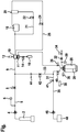
- An external pressure bottle 2 filled with a fluid refrigerant to be supplied to the refrigeration unit 48 is connected by means of a system inlet (low pressure) coupling 4 to a charging hose 5 of the filling system.
- the charging hose 5 is provided with an inlet pressure sensor 6 which is configured to measure the pressure of the refrigerant supplied by the external pressure bottle 2 to the inlet hose 5.
- the opposing end of the inlet hose 5 is connected by means of a switchable inlet valve I to an inlet line 9 which supplies the refrigerant delivered by the external pressure bottle 2 to a heated suction accumulator 10.
- the heated suction accumulator 10 is configured to heat the refrigerant, if necessary, in order to ensure that all the refrigerant is vaporized.
- a heated suction accumulator pressure sensor L2 is located at the heated suction accumulator 10 in order to measure the pressure of the refrigerant collected within the heated suction accumulator 10.
- An oil drain valve 14 and an oil drain 16 are serially connected to the bottom of the heated suction accumulator 10 in order to drain oil, which has been separated from the refrigerant within the heated suction accumulator 10 and collected at the bottom of the heated suction accumulator 10.
- An outlet side of the heated suction accumulator 10 is fluidly connected to a low pressure inlet of a compressor 18, the compressor 18 being configured for compressing the refrigerant to an increased pressure level.
- a high pressure outlet side of the compressor 18 provides pressurized refrigerant and is fluidly connected to an oil separator 20 which is configured for separating oil, which is used for lubricating the compressor 20 and a portion of which is added to the refrigerant in the compressor 18, from the refrigerant.
- the oil separated by the oil separator 20 is delivered via an oil return line 21 and an oil return valve 22 back to the inlet side of the compressor 18 in order to avoid that the compressor 18 runs out of oil after some time of operation.
- the compressor 18 running out of oil could result in a jamming and/or even serious damage of the compressor 18.
- the refrigerant leaving the oil separator 20 flows through a high pressure line 25 comprising a compressor outlet valve 24 to a heating coil 11, which is arranged within the heated suction accumulator 10 in order to transfer heat from the high pressurized, high temperature refrigerant leaving the compressor 18 to the low pressure refrigerant before it flows into the compressor 18, in order to ensure that only vaporized refrigerant enters into the compressor 18, as it has been described before.
- the refrigerant is delivered via a receiver inlet valve 26 into a receiver 28 of the system.
- the receiver 28 is provided with an receiver temperature sensor 36, which is configured for measuring the temperature of the refrigerant collected within the receiver 28.
- the receiver 28 is further provided with a receiver pressure sensor 30, which is configured for measuring the pressure of the refrigerant collected within the receiver 28.
- An orifice 32 and a venting valve 34 which are fluidly connected to the receiver 28, allow to vent the receiver 28 by dispensing excessive gas/air from the receiver 28 to the environment.
- the receiver 28 is further provided with a receiver outlet line 29 comprising a receiver outlet valve 40 allowing to extract pressurized refrigerant from the receiver 28.
- the receiver outlet line 29 branches into a system outlet line 31, which is fluidly connected to an refrigeration unit 48 by means of a system outlet valve 41, an outlet hose 35 and a high pressure outlet coupling 46, and a refrigerant return line 33 fluidly connecting the receiver outlet line 29 to the inlet side of the heated suction accumulator 10.
- the refrigerant return line 33 comprises a switchable refrigerant return valve 42, which allows to control the flow of refrigerant through the refrigerant return line 33, and a one-way-valve 44, which inhibits an undesired flow of refrigerant from the inlet line 9 to the receiver outlet line 29.
- the pressure and the temperature of the refrigerant-air-mixture collected within the receiver 28 are measured by means of the receiver pressure sensor 30 and the receiver temperature sensor 36, respectively.
- the system is stopped and an alarm is triggered if the change of the air pressure of the refrigerant-air-mixture within the receiver 38 over time exceeds a predetermined margin.
- a fast change of the air pressure of the refrigerant-air-mixture is a reliable indicator for a leak or another problem in the system, and a state in which the ratio of air in the refrigerant-air-mixture approaches an explosive state may be detected early and reliably.
- Countermeasures and/or additional safety measures may be triggered by the control unit 38 in order to avoid an ignition and/or explosion of the refrigerant-air-mixture.
- These countermeasures and/or safety measures may include to vent the receiver 28 by dispensing excessive gas/air from the receiver 28 to the environment via the venting valve 34 in order to reduce the pressure within the receiver 28, to switch off all electrical device in the environment of the system and/or to fill the environment of the system with an inflammable gas.
- margins of 1,0 bar and L,7 bar above the saturation pressure which provide a large safety margin
- margins of different margins which are considered as being appropriate in the special situation, may be used.
- the selection of the margins may e.g. depend on the type of refrigerant used, the typical environmental conditions and the actual safety requirements.
Landscapes
- Engineering & Computer Science (AREA)
- Physics & Mathematics (AREA)
- Mechanical Engineering (AREA)
- Thermal Sciences (AREA)
- General Engineering & Computer Science (AREA)
- Air-Conditioning For Vehicles (AREA)
- Measuring Fluid Pressure (AREA)
- Air Conditioning Control Device (AREA)
Claims (10)
- Verfahren zum Vermeiden explosiver Bedingungen, wenn ein Füllsystem betrieben wird, das konfiguriert ist, ein Kältemittel zu einem Kühlsystem (48) zu überführen, wobei das Füllsystem einen Empfänger (28) zum Sammeln eines Kältemittel-Luft-Gemisches umfasst,
wobei das Verfahren die Schritte umfasst:- Bestimmen des Sättigungsdrucks des Kältemittels bei den tatsächlichen Umweltbedingungen;- Bestimmen des Luftdrucks des Kältemittel-Luft-Gemisches im Empfänger (28);wobei das Verfahren dadurch gekennzeichnet ist, dass es den Schritt umfasst:- Stoppen des Betriebs des Füllsystems oder alternativ Stoppen des Betriebs des Füllsystems und Ausgeben eines Alarms, falls der Luftdruck des Kältemittel-Luft-Gemisches im Empfänger (28) den Sättigungsdruck des Kältemittels um mehr als eine vorbestimmte Spanne übersteigt oder falls die Änderung des Luftdrucks des Kältemittel-Luft-Gemisches im Empfänger (28) im Laufe der Zeit eine vorbestimmte Spanne übersteigt. - Verfahren nach Anspruch 1, wobei der Schritt zum Bestimmen des Sättigungsdrucks des Kältemittels den Schritt zum Bestimmen der Temperatur des Kältemittels enthält.
- Verfahren nach Anspruch 1 oder 2, wobei der Schritt zum Bestimmen des Luftdrucks des Kältemittel-Luft-Gemisches im Empfänger (28) die Schritte enthält:- Bestimmen des Gesamtdrucks im Empfänger (28);- Bestimmen des Kältemitteldrucks im Empfänger (28);- Bestimmen des Luftdrucks des Kältemittel-Luft-Gemisches aus dem Gesamtdruck und dem Kältemitteldruck.
- Verfahren nach Anspruch 3, wobei der Gesamtdruck im Empfänger (28) mit Hilfe eines Drucksensors (30) bestimmt wird.
- Verfahren nach Anspruch 3 oder 4, wobei der Kältemitteldruck durch Messen der Temperatur des Kältemittel-Luft-Gemisches bestimmt wird.
- Verfahren nach einem der vorstehenden Ansprüche, wobei der Betrieb des Kühlsystems (48) gestoppt wird, falls der Luftdruck des Kältemittel-Luft-Gemisches im Empfänger (28) den Sättigungsdruck des Kältemittels um mehr als eine erste Spanne übersteigt, und ein Alarm ausgegeben wird, falls der Luftdruck des Kältemittel-Luft-Gemisches im Empfänger (28) den Sättigungsdruck des Kältemittels um mehr als eine zweite Spanne übersteigt.
- Verfahren nach Anspruch 6, wobei die erste Spanne kleiner ist als die zweite Spanne.
- Verfahren nach Anspruch 6 oder 7, wobei die erste Spanne 1,0 Bar ist.
- Verfahren nach einem der vorstehenden Ansprüche, wobei die zweite Spanne 1,7 Bar ist.
- Füllsystem zum Vermeiden explosiver Bedingungen beim Überführen von Kältemittel zu einem Kühlsystem (48), das Füllsystem umfassend einen Empfänger (28) zum Sammeln eines Kältemittel-Luft-Gemisches, einen Drucksensor (30) zum Messen des Drucks im Empfänger (28), einen Temperatursensor (36) zum Messen der Temperatur des Kältemittel-Luft-Gemisches im Empfänger (28) und eine Steuereinheit (38), die konfiguriert ist, basierend auf dem Druck, der vom Drucksensor (30) gemessen wird, und der Temperatur, die vom Temperatursensor (36) gemessen wird, den Sättigungsdruck des Kältemittels und den Luftdruck des Kältemittel-Luft-Gemisches im Empfänger (28) zu bestimmen;
dadurch gekennzeichnet, dass die Steuereinheit (38) konfiguriert ist,
den Betrieb des Füllsystems zu stoppen oder alternativ den Betrieb des Füllsystem zu stoppen und einen Alarm auszugeben, falls der Luftdruck des Kältemittel-Luft-Gemisches im Empfänger (28) den Sättigungsdruck des Kältemittels um mehr als eine vorbestimmte Spanne übersteigt oder falls die Änderung des Luftdrucks des Kältemittel-Luft-Gemisches im Empfänger im Laufe der Zeit eine vorbestimmte Spanne übersteigt.
Priority Applications (3)
| Application Number | Priority Date | Filing Date | Title |
|---|---|---|---|
| EP11178644.8A EP2562491B1 (de) | 2011-08-24 | 2011-08-24 | Kühlsystem und Verfahren zum Betreiben eines Kühlsystems |
| CN201210301785.7A CN102954638B (zh) | 2011-08-24 | 2012-08-23 | 制冷系统以及操作制冷系统的方法 |
| US13/593,751 US8955342B2 (en) | 2011-08-24 | 2012-08-24 | Refrigeration system and method of operating a refrigeration system |
Applications Claiming Priority (1)
| Application Number | Priority Date | Filing Date | Title |
|---|---|---|---|
| EP11178644.8A EP2562491B1 (de) | 2011-08-24 | 2011-08-24 | Kühlsystem und Verfahren zum Betreiben eines Kühlsystems |
Publications (2)
| Publication Number | Publication Date |
|---|---|
| EP2562491A1 EP2562491A1 (de) | 2013-02-27 |
| EP2562491B1 true EP2562491B1 (de) | 2019-05-01 |
Family
ID=44785254
Family Applications (1)
| Application Number | Title | Priority Date | Filing Date |
|---|---|---|---|
| EP11178644.8A Active EP2562491B1 (de) | 2011-08-24 | 2011-08-24 | Kühlsystem und Verfahren zum Betreiben eines Kühlsystems |
Country Status (3)
| Country | Link |
|---|---|
| US (1) | US8955342B2 (de) |
| EP (1) | EP2562491B1 (de) |
| CN (1) | CN102954638B (de) |
Families Citing this family (6)
| Publication number | Priority date | Publication date | Assignee | Title |
|---|---|---|---|---|
| US9857111B2 (en) * | 2013-12-04 | 2018-01-02 | Bosch Automotive Service Solutions Inc. | Method and apparatus for recovering refrigerant from an air conditioning system |
| CN106796068A (zh) * | 2014-04-24 | 2017-05-31 | 罗伯特·博世有限公司 | 用于向空调线路内注入油的系统和方法 |
| US11248825B2 (en) * | 2017-08-30 | 2022-02-15 | Bosch Automotive Service Solutions Inc. | Tank temperature probe with positional sensor |
| DE102017120384B4 (de) * | 2017-09-05 | 2023-03-16 | Fft Produktionssysteme Gmbh & Co. Kg | Befüllvorrichtung zum Befüllen von Klimaanlagen mit CO2 |
| CN107701058B (zh) * | 2017-10-30 | 2019-07-09 | 广东坚朗五金制品股份有限公司 | 卡锁机构及推拉门密封组件 |
| JP6746742B1 (ja) * | 2019-03-15 | 2020-08-26 | 三菱重工サーマルシステムズ株式会社 | 車両用空調システムおよび車両用空調システムの制御方法 |
Citations (1)
| Publication number | Priority date | Publication date | Assignee | Title |
|---|---|---|---|---|
| EP2525205A1 (de) * | 2011-05-17 | 2012-11-21 | Service Solutions U.S. LLC | Druckabfallleckage-Prüfverfahren und Vorrichtung |
Family Cites Families (21)
| Publication number | Priority date | Publication date | Assignee | Title |
|---|---|---|---|---|
| US4285206A (en) * | 1979-02-05 | 1981-08-25 | Draf Tool Co., Inc. | Automatic refrigerant recovery, purification and recharge apparatus |
| US4805416A (en) * | 1987-11-04 | 1989-02-21 | Kent-Moore Corporation | Refrigerant recovery, purification and recharging system |
| US5063749A (en) * | 1989-09-11 | 1991-11-12 | Kent-Moore Corporation | Refrigerant handling system with air purge and multiple refrigerant capabilities |
| US5005369A (en) * | 1989-09-11 | 1991-04-09 | Kent-Moore Corporation | Refrigerant purification with automatic air purge |
| US5347823A (en) * | 1990-04-06 | 1994-09-20 | Alsenz Richard H | Refrigeration system utilizing an enthalpy expansion jet compressor |
| US5289693A (en) * | 1993-01-22 | 1994-03-01 | Major Thomas O | Refrigerant recovery and purification apparatus with telecommunication monitoring facilitation device |
| US5285647B1 (en) * | 1993-03-08 | 1999-02-23 | Spx Corp | Refrigerant handling system with air purge and multiple refrigerant capabilities |
| EP0787958A4 (de) * | 1994-10-25 | 1998-09-09 | Daikin Ind Ltd | Klimaanlage und verfahren zur steuerung desses waschvorganges |
| CN1169771A (zh) * | 1994-10-25 | 1998-01-07 | 大金工业株式会社 | 空调机及其清洗运转控制方法 |
| US5802860A (en) * | 1997-04-25 | 1998-09-08 | Tyler Refrigeration Corporation | Refrigeration system |
| JPH1123115A (ja) * | 1997-06-30 | 1999-01-26 | Denso Corp | 冷凍サイクル |
| US6862894B1 (en) * | 2004-02-04 | 2005-03-08 | Donald R. Miles | Adaptive auxiliary condensing device and method |
| WO2005078364A1 (ja) * | 2004-02-17 | 2005-08-25 | Matsushita Electric Industrial Co., Ltd. | 可燃性冷媒処理装置及び処理方法 |
| JP4354881B2 (ja) * | 2004-06-23 | 2009-10-28 | 三菱電機エンジニアリング株式会社 | 冷媒充填装置 |
| EP1795831B1 (de) * | 2004-09-30 | 2014-02-12 | Mayekawa Mfg. Co., Ltd. | Ammoniak/co2-kühlsystem |
| DK176740B1 (da) * | 2004-12-14 | 2009-05-25 | Agramkow Fluid Systems As | Fremgangsmåde og anlæg til kölemiddelpåfyldning på et köleanlæg |
| ES2728954T3 (es) * | 2005-10-25 | 2019-10-29 | Mitsubishi Electric Corp | Aparato acondicionador de aire, método de llenado de refrigerante en aparato de acondicionador de aire, método para evaluar el estado de llenado de refrigerante en aparato de acondicionador de aire y método de llenado de refrigerante/limpieza de tuberías para aparato acondicionador de aire |
| JP5324749B2 (ja) * | 2006-09-11 | 2013-10-23 | ダイキン工業株式会社 | 冷凍装置 |
| JP5332093B2 (ja) * | 2006-09-11 | 2013-11-06 | ダイキン工業株式会社 | 冷凍装置 |
| JP4225357B2 (ja) * | 2007-04-13 | 2009-02-18 | ダイキン工業株式会社 | 冷媒充填装置、冷凍装置及び冷媒充填方法 |
| US20130032220A1 (en) * | 2010-01-22 | 2013-02-07 | Louis Cording | System and a method for the flushing of air condition systems |
-
2011
- 2011-08-24 EP EP11178644.8A patent/EP2562491B1/de active Active
-
2012
- 2012-08-23 CN CN201210301785.7A patent/CN102954638B/zh active Active
- 2012-08-24 US US13/593,751 patent/US8955342B2/en active Active
Patent Citations (1)
| Publication number | Priority date | Publication date | Assignee | Title |
|---|---|---|---|---|
| EP2525205A1 (de) * | 2011-05-17 | 2012-11-21 | Service Solutions U.S. LLC | Druckabfallleckage-Prüfverfahren und Vorrichtung |
Also Published As
| Publication number | Publication date |
|---|---|
| US20130047637A1 (en) | 2013-02-28 |
| US8955342B2 (en) | 2015-02-17 |
| CN102954638A (zh) | 2013-03-06 |
| CN102954638B (zh) | 2017-03-01 |
| EP2562491A1 (de) | 2013-02-27 |
Similar Documents
| Publication | Publication Date | Title |
|---|---|---|
| EP2562491B1 (de) | Kühlsystem und Verfahren zum Betreiben eines Kühlsystems | |
| EP2526354B1 (de) | System und verfahren zum spülen von klimaanlagensystemen | |
| CN101558271B (zh) | 用于空调的泄漏检查的空调维护设备 | |
| EP3543048B1 (de) | Verfahren zur identifizierung und betätigung von luftspülung im sicheren modus | |
| CN106016867A (zh) | 一种冷媒充注方法、冷媒充注系统及空调器 | |
| CN102725155A (zh) | 用于维护汽车空调装置的方法和用于该方法的维修设备 | |
| CN104567158B (zh) | 控制制冷机系统中制冷液泄漏量的系统及方法 | |
| CN103673398B (zh) | 压缩机回油系统及压缩机的回油状态检测方法 | |
| US20010025496A1 (en) | Filling device for motor vehicle air-conditioning systems | |
| US20090235673A1 (en) | Detection of refrigerant release in co2 refrigerant systems | |
| CN201432658Y (zh) | 安全预警状态下的制动和紧急制动系统 | |
| WO2005066556A1 (en) | Refrigerant system pressure control for storage and transportation | |
| CN106091500B (zh) | 一种安全储液罐装置及采用其的空调 | |
| US9835392B2 (en) | Method for preventing and detecting coolant discharges from complex hydraulic systems | |
| CN206073526U (zh) | 一种安全储液罐装置及采用其的空调 | |
| US9447998B2 (en) | Method and apparatus for improving the charge accuracy of a refrigerant recovery unit | |
| CN113623907A (zh) | 空调制冷剂回收及充注系统及其控制方法 | |
| CN110926073A (zh) | 监测压缩制冷系统运行中工质的状态的装置和方法 | |
| EP3162598B1 (de) | Station zur rückgewinnung- und aufladung eines kältemittels einer kraftfahrzeugklimaanlage mit erkennung von nichtkondensierbarem gas, und verfahren dafür | |
| KR101523227B1 (ko) | 가스를 매개체로 하는 반도체 제조공정설비용 온도 제어시스템의 냉매 누출 점검시스템 및 이를 이용한 냉매 누출 점검방법 | |
| RU115772U1 (ru) | Система приема, хранения и отпуска нефти и нефтепродуктов | |
| JP2017210873A (ja) | 防爆型冷凍機、これを含む冷凍装置 | |
| US20120011863A1 (en) | Methods of servicing mobile air conditioning systems | |
| EP2802828A2 (de) | Verfahren zum betrieb einer kältemittelrückgewinnungs- und nachfüllvorrichtung | |
| WO2023103111A1 (zh) | 一种集成控制阀和冷媒充注机 |
Legal Events
| Date | Code | Title | Description |
|---|---|---|---|
| PUAI | Public reference made under article 153(3) epc to a published international application that has entered the european phase |
Free format text: ORIGINAL CODE: 0009012 |
|
| AK | Designated contracting states |
Kind code of ref document: A1 Designated state(s): AL AT BE BG CH CY CZ DE DK EE ES FI FR GB GR HR HU IE IS IT LI LT LU LV MC MK MT NL NO PL PT RO RS SE SI SK SM TR |
|
| AX | Request for extension of the european patent |
Extension state: BA ME |
|
| 17P | Request for examination filed |
Effective date: 20130827 |
|
| RBV | Designated contracting states (corrected) |
Designated state(s): AL AT BE BG CH CY CZ DE DK EE ES FI FR GB GR HR HU IE IS IT LI LT LU LV MC MK MT NL NO PL PT RO RS SE SI SK SM TR |
|
| RAP1 | Party data changed (applicant data changed or rights of an application transferred) |
Owner name: MAHLE INTERNATIONAL GMBH |
|
| STAA | Information on the status of an ep patent application or granted ep patent |
Free format text: STATUS: EXAMINATION IS IN PROGRESS |
|
| 17Q | First examination report despatched |
Effective date: 20180406 |
|
| GRAP | Despatch of communication of intention to grant a patent |
Free format text: ORIGINAL CODE: EPIDOSNIGR1 |
|
| STAA | Information on the status of an ep patent application or granted ep patent |
Free format text: STATUS: GRANT OF PATENT IS INTENDED |
|
| INTG | Intention to grant announced |
Effective date: 20181121 |
|
| GRAJ | Information related to disapproval of communication of intention to grant by the applicant or resumption of examination proceedings by the epo deleted |
Free format text: ORIGINAL CODE: EPIDOSDIGR1 |
|
| STAA | Information on the status of an ep patent application or granted ep patent |
Free format text: STATUS: EXAMINATION IS IN PROGRESS |
|
| GRAP | Despatch of communication of intention to grant a patent |
Free format text: ORIGINAL CODE: EPIDOSNIGR1 |
|
| STAA | Information on the status of an ep patent application or granted ep patent |
Free format text: STATUS: GRANT OF PATENT IS INTENDED |
|
| INTC | Intention to grant announced (deleted) | ||
| INTG | Intention to grant announced |
Effective date: 20190214 |
|
| GRAS | Grant fee paid |
Free format text: ORIGINAL CODE: EPIDOSNIGR3 |
|
| GRAA | (expected) grant |
Free format text: ORIGINAL CODE: 0009210 |
|
| STAA | Information on the status of an ep patent application or granted ep patent |
Free format text: STATUS: THE PATENT HAS BEEN GRANTED |
|
| AK | Designated contracting states |
Kind code of ref document: B1 Designated state(s): AL AT BE BG CH CY CZ DE DK EE ES FI FR GB GR HR HU IE IS IT LI LT LU LV MC MK MT NL NO PL PT RO RS SE SI SK SM TR |
|
| REG | Reference to a national code |
Ref country code: GB Ref legal event code: FG4D |
|
| REG | Reference to a national code |
Ref country code: CH Ref legal event code: EP Ref country code: AT Ref legal event code: REF Ref document number: 1127478 Country of ref document: AT Kind code of ref document: T Effective date: 20190515 |
|
| REG | Reference to a national code |
Ref country code: DE Ref legal event code: R096 Ref document number: 602011058453 Country of ref document: DE |
|
| REG | Reference to a national code |
Ref country code: IE Ref legal event code: FG4D |
|
| REG | Reference to a national code |
Ref country code: NL Ref legal event code: MP Effective date: 20190501 |
|
| REG | Reference to a national code |
Ref country code: LT Ref legal event code: MG4D |
|
| PG25 | Lapsed in a contracting state [announced via postgrant information from national office to epo] |
Ref country code: HR Free format text: LAPSE BECAUSE OF FAILURE TO SUBMIT A TRANSLATION OF THE DESCRIPTION OR TO PAY THE FEE WITHIN THE PRESCRIBED TIME-LIMIT Effective date: 20190501 Ref country code: NO Free format text: LAPSE BECAUSE OF FAILURE TO SUBMIT A TRANSLATION OF THE DESCRIPTION OR TO PAY THE FEE WITHIN THE PRESCRIBED TIME-LIMIT Effective date: 20190801 Ref country code: SE Free format text: LAPSE BECAUSE OF FAILURE TO SUBMIT A TRANSLATION OF THE DESCRIPTION OR TO PAY THE FEE WITHIN THE PRESCRIBED TIME-LIMIT Effective date: 20190501 Ref country code: FI Free format text: LAPSE BECAUSE OF FAILURE TO SUBMIT A TRANSLATION OF THE DESCRIPTION OR TO PAY THE FEE WITHIN THE PRESCRIBED TIME-LIMIT Effective date: 20190501 Ref country code: AL Free format text: LAPSE BECAUSE OF FAILURE TO SUBMIT A TRANSLATION OF THE DESCRIPTION OR TO PAY THE FEE WITHIN THE PRESCRIBED TIME-LIMIT Effective date: 20190501 Ref country code: PT Free format text: LAPSE BECAUSE OF FAILURE TO SUBMIT A TRANSLATION OF THE DESCRIPTION OR TO PAY THE FEE WITHIN THE PRESCRIBED TIME-LIMIT Effective date: 20190901 Ref country code: NL Free format text: LAPSE BECAUSE OF FAILURE TO SUBMIT A TRANSLATION OF THE DESCRIPTION OR TO PAY THE FEE WITHIN THE PRESCRIBED TIME-LIMIT Effective date: 20190501 Ref country code: ES Free format text: LAPSE BECAUSE OF FAILURE TO SUBMIT A TRANSLATION OF THE DESCRIPTION OR TO PAY THE FEE WITHIN THE PRESCRIBED TIME-LIMIT Effective date: 20190501 Ref country code: LT Free format text: LAPSE BECAUSE OF FAILURE TO SUBMIT A TRANSLATION OF THE DESCRIPTION OR TO PAY THE FEE WITHIN THE PRESCRIBED TIME-LIMIT Effective date: 20190501 |
|
| PG25 | Lapsed in a contracting state [announced via postgrant information from national office to epo] |
Ref country code: BG Free format text: LAPSE BECAUSE OF FAILURE TO SUBMIT A TRANSLATION OF THE DESCRIPTION OR TO PAY THE FEE WITHIN THE PRESCRIBED TIME-LIMIT Effective date: 20190801 Ref country code: RS Free format text: LAPSE BECAUSE OF FAILURE TO SUBMIT A TRANSLATION OF THE DESCRIPTION OR TO PAY THE FEE WITHIN THE PRESCRIBED TIME-LIMIT Effective date: 20190501 Ref country code: GR Free format text: LAPSE BECAUSE OF FAILURE TO SUBMIT A TRANSLATION OF THE DESCRIPTION OR TO PAY THE FEE WITHIN THE PRESCRIBED TIME-LIMIT Effective date: 20190802 Ref country code: LV Free format text: LAPSE BECAUSE OF FAILURE TO SUBMIT A TRANSLATION OF THE DESCRIPTION OR TO PAY THE FEE WITHIN THE PRESCRIBED TIME-LIMIT Effective date: 20190501 |
|
| REG | Reference to a national code |
Ref country code: AT Ref legal event code: MK05 Ref document number: 1127478 Country of ref document: AT Kind code of ref document: T Effective date: 20190501 |
|
| PG25 | Lapsed in a contracting state [announced via postgrant information from national office to epo] |
Ref country code: IS Free format text: LAPSE BECAUSE OF FAILURE TO SUBMIT A TRANSLATION OF THE DESCRIPTION OR TO PAY THE FEE WITHIN THE PRESCRIBED TIME-LIMIT Effective date: 20190901 |
|
| PG25 | Lapsed in a contracting state [announced via postgrant information from national office to epo] |
Ref country code: DK Free format text: LAPSE BECAUSE OF FAILURE TO SUBMIT A TRANSLATION OF THE DESCRIPTION OR TO PAY THE FEE WITHIN THE PRESCRIBED TIME-LIMIT Effective date: 20190501 Ref country code: AT Free format text: LAPSE BECAUSE OF FAILURE TO SUBMIT A TRANSLATION OF THE DESCRIPTION OR TO PAY THE FEE WITHIN THE PRESCRIBED TIME-LIMIT Effective date: 20190501 Ref country code: CZ Free format text: LAPSE BECAUSE OF FAILURE TO SUBMIT A TRANSLATION OF THE DESCRIPTION OR TO PAY THE FEE WITHIN THE PRESCRIBED TIME-LIMIT Effective date: 20190501 Ref country code: RO Free format text: LAPSE BECAUSE OF FAILURE TO SUBMIT A TRANSLATION OF THE DESCRIPTION OR TO PAY THE FEE WITHIN THE PRESCRIBED TIME-LIMIT Effective date: 20190501 Ref country code: EE Free format text: LAPSE BECAUSE OF FAILURE TO SUBMIT A TRANSLATION OF THE DESCRIPTION OR TO PAY THE FEE WITHIN THE PRESCRIBED TIME-LIMIT Effective date: 20190501 Ref country code: SK Free format text: LAPSE BECAUSE OF FAILURE TO SUBMIT A TRANSLATION OF THE DESCRIPTION OR TO PAY THE FEE WITHIN THE PRESCRIBED TIME-LIMIT Effective date: 20190501 |
|
| REG | Reference to a national code |
Ref country code: DE Ref legal event code: R097 Ref document number: 602011058453 Country of ref document: DE |
|
| PG25 | Lapsed in a contracting state [announced via postgrant information from national office to epo] |
Ref country code: SM Free format text: LAPSE BECAUSE OF FAILURE TO SUBMIT A TRANSLATION OF THE DESCRIPTION OR TO PAY THE FEE WITHIN THE PRESCRIBED TIME-LIMIT Effective date: 20190501 Ref country code: IT Free format text: LAPSE BECAUSE OF FAILURE TO SUBMIT A TRANSLATION OF THE DESCRIPTION OR TO PAY THE FEE WITHIN THE PRESCRIBED TIME-LIMIT Effective date: 20190501 |
|
| PLBE | No opposition filed within time limit |
Free format text: ORIGINAL CODE: 0009261 |
|
| STAA | Information on the status of an ep patent application or granted ep patent |
Free format text: STATUS: NO OPPOSITION FILED WITHIN TIME LIMIT |
|
| PG25 | Lapsed in a contracting state [announced via postgrant information from national office to epo] |
Ref country code: TR Free format text: LAPSE BECAUSE OF FAILURE TO SUBMIT A TRANSLATION OF THE DESCRIPTION OR TO PAY THE FEE WITHIN THE PRESCRIBED TIME-LIMIT Effective date: 20190501 |
|
| 26N | No opposition filed |
Effective date: 20200204 |
|
| GBPC | Gb: european patent ceased through non-payment of renewal fee |
Effective date: 20190824 |
|
| PG25 | Lapsed in a contracting state [announced via postgrant information from national office to epo] |
Ref country code: PL Free format text: LAPSE BECAUSE OF FAILURE TO SUBMIT A TRANSLATION OF THE DESCRIPTION OR TO PAY THE FEE WITHIN THE PRESCRIBED TIME-LIMIT Effective date: 20190501 |
|
| PG25 | Lapsed in a contracting state [announced via postgrant information from national office to epo] |
Ref country code: LU Free format text: LAPSE BECAUSE OF NON-PAYMENT OF DUE FEES Effective date: 20190824 Ref country code: SI Free format text: LAPSE BECAUSE OF FAILURE TO SUBMIT A TRANSLATION OF THE DESCRIPTION OR TO PAY THE FEE WITHIN THE PRESCRIBED TIME-LIMIT Effective date: 20190501 Ref country code: LI Free format text: LAPSE BECAUSE OF NON-PAYMENT OF DUE FEES Effective date: 20190831 Ref country code: CH Free format text: LAPSE BECAUSE OF NON-PAYMENT OF DUE FEES Effective date: 20190831 Ref country code: MC Free format text: LAPSE BECAUSE OF FAILURE TO SUBMIT A TRANSLATION OF THE DESCRIPTION OR TO PAY THE FEE WITHIN THE PRESCRIBED TIME-LIMIT Effective date: 20190501 |
|
| REG | Reference to a national code |
Ref country code: BE Ref legal event code: MM Effective date: 20190831 |
|
| PG25 | Lapsed in a contracting state [announced via postgrant information from national office to epo] |
Ref country code: IE Free format text: LAPSE BECAUSE OF NON-PAYMENT OF DUE FEES Effective date: 20190824 Ref country code: FR Free format text: LAPSE BECAUSE OF NON-PAYMENT OF DUE FEES Effective date: 20190831 |
|
| PG25 | Lapsed in a contracting state [announced via postgrant information from national office to epo] |
Ref country code: BE Free format text: LAPSE BECAUSE OF NON-PAYMENT OF DUE FEES Effective date: 20190831 Ref country code: GB Free format text: LAPSE BECAUSE OF NON-PAYMENT OF DUE FEES Effective date: 20190824 |
|
| PG25 | Lapsed in a contracting state [announced via postgrant information from national office to epo] |
Ref country code: CY Free format text: LAPSE BECAUSE OF FAILURE TO SUBMIT A TRANSLATION OF THE DESCRIPTION OR TO PAY THE FEE WITHIN THE PRESCRIBED TIME-LIMIT Effective date: 20190501 |
|
| PG25 | Lapsed in a contracting state [announced via postgrant information from national office to epo] |
Ref country code: HU Free format text: LAPSE BECAUSE OF FAILURE TO SUBMIT A TRANSLATION OF THE DESCRIPTION OR TO PAY THE FEE WITHIN THE PRESCRIBED TIME-LIMIT; INVALID AB INITIO Effective date: 20110824 Ref country code: MT Free format text: LAPSE BECAUSE OF FAILURE TO SUBMIT A TRANSLATION OF THE DESCRIPTION OR TO PAY THE FEE WITHIN THE PRESCRIBED TIME-LIMIT Effective date: 20190501 |
|
| PG25 | Lapsed in a contracting state [announced via postgrant information from national office to epo] |
Ref country code: MK Free format text: LAPSE BECAUSE OF FAILURE TO SUBMIT A TRANSLATION OF THE DESCRIPTION OR TO PAY THE FEE WITHIN THE PRESCRIBED TIME-LIMIT Effective date: 20190501 |
|
| PGFP | Annual fee paid to national office [announced via postgrant information from national office to epo] |
Ref country code: DE Payment date: 20230821 Year of fee payment: 13 |