EP2562371B1 - Système de prédiction d'émissions pour système de génération de puissance - Google Patents
Système de prédiction d'émissions pour système de génération de puissance Download PDFInfo
- Publication number
- EP2562371B1 EP2562371B1 EP12181227.5A EP12181227A EP2562371B1 EP 2562371 B1 EP2562371 B1 EP 2562371B1 EP 12181227 A EP12181227 A EP 12181227A EP 2562371 B1 EP2562371 B1 EP 2562371B1
- Authority
- EP
- European Patent Office
- Prior art keywords
- emissions
- steam
- power generation
- operational
- temperature
- Prior art date
- Legal status (The legal status is an assumption and is not a legal conclusion. Google has not performed a legal analysis and makes no representation as to the accuracy of the status listed.)
- Active
Links
- 238000010248 power generation Methods 0.000 title claims description 63
- 238000011084 recovery Methods 0.000 claims description 3
- 239000007789 gas Substances 0.000 description 45
- 238000000034 method Methods 0.000 description 36
- 230000008569 process Effects 0.000 description 27
- MWUXSHHQAYIFBG-UHFFFAOYSA-N Nitric oxide Chemical compound O=[N] MWUXSHHQAYIFBG-UHFFFAOYSA-N 0.000 description 12
- 230000001052 transient effect Effects 0.000 description 12
- 238000004590 computer program Methods 0.000 description 10
- 238000010586 diagram Methods 0.000 description 10
- 230000000694 effects Effects 0.000 description 10
- 230000006870 function Effects 0.000 description 7
- 239000000126 substance Substances 0.000 description 5
- UGFAIRIUMAVXCW-UHFFFAOYSA-N Carbon monoxide Chemical compound [O+]#[C-] UGFAIRIUMAVXCW-UHFFFAOYSA-N 0.000 description 4
- 238000004519 manufacturing process Methods 0.000 description 4
- 229910002091 carbon monoxide Inorganic materials 0.000 description 3
- 238000004891 communication Methods 0.000 description 3
- 230000003247 decreasing effect Effects 0.000 description 3
- 230000003287 optical effect Effects 0.000 description 3
- 230000008646 thermal stress Effects 0.000 description 3
- 230000015572 biosynthetic process Effects 0.000 description 2
- 229930195733 hydrocarbon Natural products 0.000 description 2
- 150000002430 hydrocarbons Chemical class 0.000 description 2
- 239000000463 material Substances 0.000 description 2
- 229910052751 metal Inorganic materials 0.000 description 2
- 239000002184 metal Substances 0.000 description 2
- 239000013307 optical fiber Substances 0.000 description 2
- 238000012545 processing Methods 0.000 description 2
- 239000004215 Carbon black (E152) Substances 0.000 description 1
- 230000009286 beneficial effect Effects 0.000 description 1
- 230000008901 benefit Effects 0.000 description 1
- 230000005540 biological transmission Effects 0.000 description 1
- 238000013461 design Methods 0.000 description 1
- 230000006866 deterioration Effects 0.000 description 1
- 230000007613 environmental effect Effects 0.000 description 1
- 239000012530 fluid Substances 0.000 description 1
- 230000006872 improvement Effects 0.000 description 1
- 238000012544 monitoring process Methods 0.000 description 1
- 230000000644 propagated effect Effects 0.000 description 1
- 230000001105 regulatory effect Effects 0.000 description 1
- 230000004044 response Effects 0.000 description 1
- 239000004065 semiconductor Substances 0.000 description 1
- 230000035882 stress Effects 0.000 description 1
- 238000012546 transfer Methods 0.000 description 1
- XLYOFNOQVPJJNP-UHFFFAOYSA-N water Substances O XLYOFNOQVPJJNP-UHFFFAOYSA-N 0.000 description 1
Images

Classifications
-
- F—MECHANICAL ENGINEERING; LIGHTING; HEATING; WEAPONS; BLASTING
- F22—STEAM GENERATION
- F22B—METHODS OF STEAM GENERATION; STEAM BOILERS
- F22B1/00—Methods of steam generation characterised by form of heating method
- F22B1/02—Methods of steam generation characterised by form of heating method by exploitation of the heat content of hot heat carriers
- F22B1/18—Methods of steam generation characterised by form of heating method by exploitation of the heat content of hot heat carriers the heat carrier being a hot gas, e.g. waste gas such as exhaust gas of internal-combustion engines
- F22B1/1807—Methods of steam generation characterised by form of heating method by exploitation of the heat content of hot heat carriers the heat carrier being a hot gas, e.g. waste gas such as exhaust gas of internal-combustion engines using the exhaust gases of combustion engines
- F22B1/1815—Methods of steam generation characterised by form of heating method by exploitation of the heat content of hot heat carriers the heat carrier being a hot gas, e.g. waste gas such as exhaust gas of internal-combustion engines using the exhaust gases of combustion engines using the exhaust gases of gas-turbines
-
- F—MECHANICAL ENGINEERING; LIGHTING; HEATING; WEAPONS; BLASTING
- F01—MACHINES OR ENGINES IN GENERAL; ENGINE PLANTS IN GENERAL; STEAM ENGINES
- F01K—STEAM ENGINE PLANTS; STEAM ACCUMULATORS; ENGINE PLANTS NOT OTHERWISE PROVIDED FOR; ENGINES USING SPECIAL WORKING FLUIDS OR CYCLES
- F01K23/00—Plants characterised by more than one engine delivering power external to the plant, the engines being driven by different fluids
- F01K23/02—Plants characterised by more than one engine delivering power external to the plant, the engines being driven by different fluids the engine cycles being thermally coupled
- F01K23/06—Plants characterised by more than one engine delivering power external to the plant, the engines being driven by different fluids the engine cycles being thermally coupled combustion heat from one cycle heating the fluid in another cycle
- F01K23/10—Plants characterised by more than one engine delivering power external to the plant, the engines being driven by different fluids the engine cycles being thermally coupled combustion heat from one cycle heating the fluid in another cycle with exhaust fluid of one cycle heating the fluid in another cycle
- F01K23/101—Regulating means specially adapted therefor
-
- F—MECHANICAL ENGINEERING; LIGHTING; HEATING; WEAPONS; BLASTING
- F01—MACHINES OR ENGINES IN GENERAL; ENGINE PLANTS IN GENERAL; STEAM ENGINES
- F01K—STEAM ENGINE PLANTS; STEAM ACCUMULATORS; ENGINE PLANTS NOT OTHERWISE PROVIDED FOR; ENGINES USING SPECIAL WORKING FLUIDS OR CYCLES
- F01K7/00—Steam engine plants characterised by the use of specific types of engine; Plants or engines characterised by their use of special steam systems, cycles or processes; Control means specially adapted for such systems, cycles or processes; Use of withdrawn or exhaust steam for feed-water heating
-
- F—MECHANICAL ENGINEERING; LIGHTING; HEATING; WEAPONS; BLASTING
- F22—STEAM GENERATION
- F22B—METHODS OF STEAM GENERATION; STEAM BOILERS
- F22B35/00—Control systems for steam boilers
- F22B35/007—Control systems for waste heat boilers
-
- F—MECHANICAL ENGINEERING; LIGHTING; HEATING; WEAPONS; BLASTING
- F22—STEAM GENERATION
- F22B—METHODS OF STEAM GENERATION; STEAM BOILERS
- F22B35/00—Control systems for steam boilers
- F22B35/18—Applications of computers to steam boiler control
-
- Y—GENERAL TAGGING OF NEW TECHNOLOGICAL DEVELOPMENTS; GENERAL TAGGING OF CROSS-SECTIONAL TECHNOLOGIES SPANNING OVER SEVERAL SECTIONS OF THE IPC; TECHNICAL SUBJECTS COVERED BY FORMER USPC CROSS-REFERENCE ART COLLECTIONS [XRACs] AND DIGESTS
- Y02—TECHNOLOGIES OR APPLICATIONS FOR MITIGATION OR ADAPTATION AGAINST CLIMATE CHANGE
- Y02E—REDUCTION OF GREENHOUSE GAS [GHG] EMISSIONS, RELATED TO ENERGY GENERATION, TRANSMISSION OR DISTRIBUTION
- Y02E20/00—Combustion technologies with mitigation potential
- Y02E20/16—Combined cycle power plant [CCPP], or combined cycle gas turbine [CCGT]
Definitions
- the subject matter disclosed herein relates to power plant systems and, more particularly, to systems for emissions sensitive transient state operation of a combined-cycle power plant system.
- emissions i.e. Carbon Monoxide (CO), hydrocarbons (UHC), Nitrogen Oxide (NOx) etc.
- CO Carbon Monoxide
- UHC hydrocarbons
- NOx Nitrogen Oxide
- a significant quantity of these emissions may be generated during states of transient operation (e.g. start-up, shutdown, etc.), where operational steam temperatures are restricted and components of the power plant system may operate with decreased loads.
- a temperature of the steam supplied to the steam turbine during startup or other transient operation may be controlled by adjusting an operating parameter of the system (e.g., the gas turbine load, gas turbine exhaust temperature, etc.).
- an operating parameter of the system e.g., the gas turbine load, gas turbine exhaust temperature, etc.
- the allowable operational steam temperature which may be supplied to the steam turbine is restricted to a temperature range which may be limited by the temperature of the steam turbine components.
- the steam temperatures within this allowable range are held close to the temperature of the system components so as to prevent against component binding and the formation of thermal stresses.
- current power plant systems consider a number of factors (e.g. effect on start-up and/or cool-down time, material effects on components, etc.). However, these systems are blind to emissions variances which may exist within the allowable steam temperature range. As such, emissions effects are not considered when adjusting operating parameters, such as the gas turbine load, to attain an operational steam temperature for transient state operation.
- JP 3672339 discloses a combined cycle system in which an initial temperature of a steam turbine component just before an increase in rotation speed is determined and said metal temperature is stored in a memory. Based upon said stored value, a lowered exhaust temperature for the gas turbine is set for generating a stem temperature in accordance with the steam turbine first stage shell inner metal temperature. This temperature is maintained for a holding time and subsequently ramped up. It is further taught that the environmental standards as to emissions shall be met. JP 3666036 generally describes providing a starting schedule considering requirements as to thermal stress and NOx exhaust rate limitation.
- a system for decreasing the emissions of a power plant system as set forth in the claims is disclosed. Further, a program product useful for operating the system and a combined cycle power generation system incorporating the system for decreasing the emissions are disclosed.
- a first aspect of the invention provides a system as defined by appended independent claim 1, the system inter alia including: at least one computing device adapted to adjust a temperature of an operational steam in a power generation system by performing actions comprising: obtaining operational data about components of a steam turbine in the power generation system, the operational data including: a temperature of the components and a set of current ambient conditions at the power generation system; determining an allowable operational steam temperature range for the steam turbine based upon the operational data; generating emissions predictions for a set of temperatures within the allowable steam temperature range; and adjusting the temperature of the operational steam based upon the emissions predictions.
- a second aspect of the invention provides a program product stored on a computer readable medium as defined by appended independent claim 9, the program product, when executed by at least one computing device, performs inter alia the following: obtains operational data about components of a steam turbine in a power generation system, the operational data including: a temperature of the components and a set of current ambient conditions at the power generation system; determines an allowable operational steam temperature range for the steam turbine based upon the operational data; generates emissions predictions for a set of temperatures within the allowable steam temperature range; and adjusts the temperature of an operational steam in the power generation system based upon the emissions predictions.
- a third aspect of the invention provides a combined cycle power generation system including: a gas turbine; a heat recovery steam generator (HRSG) operatively connected to the gas turbine; a steam turbine operatively connected to the HRSG; a generator operatively connected to at least one of the gas turbine or the steam turbine; and a system according to the first aspect, the system inter alia comprising at least one computing device communicatively connected to at least one of the gas turbine, the steam turbine and the HRSG, the at least one computing device adapted to adjust a temperature of an operational steam in the power generation system by performing actions comprising: obtaining operational data about components of the steam turbine, the operational data including: a temperature of the components and a set of current ambient conditions at the power generation system; determining an allowable operational steam temperature range for the steam turbine based upon the operational data; generating emissions predictions for a set of temperatures within the allowable steam temperature range; and adjusting the temperature of the operational steam based upon the emissions predictions.
- HRSG heat recovery steam generator
- aspects of the invention provide for systems configured to decrease the emissions of a power plant system during transient state operation. These systems predict the available improvement and/or deterioration of emissions outputs available within the allowable steam temperature matching range, and factor these effects into the steam temperature matching decision.
- Transient state operation of some power generation systems may include regulation and incremental adjustment of an operational steam temperature. This regulation and/or adjustment must keep the steam temperature within a certain range of the temperature of the system components to avoid the formation of thermal stresses.
- system operating parameters e.g., gas turbine load, gas turbine exhaust temperature, etc.
- power generation systems consider the effects on system efficiency and component material limits.
- current systems do not factor or consider emissions effects into the selection of an operational steam temperature and/or the resulting gas turbine operating condition. This lack of emissions consideration during the temperature matching process may increase the emissions output of the power generation system.
- inventions of the current invention provide for a system which predicts and considers the effects on emissions totals of a set of operational steam temperatures and corresponding gas turbine operating parameters/conditions within the allowable temperature matching range.
- the system includes a computing device which is communicatively connected to a database/memory/storage system and at least one sensor.
- the computing device is configured to identify an allowable steam temperature matching range for the power generation system based upon the temperature of the system components. Once the range has been identified, the computing device considers the gas turbine operating condition(s) necessary to achieve the various temperatures within the range, and predicts the effects that these condition(s) will have on emissions totals. As the effects on emissions of various steam temperatures are determined and factored into the matching decision, a temperature match may be made which reduces transient state emissions totals and overall plant emissions totals.
- control system described herein may be embodied as a system(s), method(s), operator display (s) or computer program product(s), e.g., as part of a power plant system, a power generation system, a turbine system, etc.
- embodiments of the present invention may take the form of an entirely hardware embodiment, an entirely software embodiment (including firmware, resident software, micro-code, etc.) or an embodiment combining software and hardware aspects that may all generally be referred to herein as a "circuit,” “module,” “network” or “system.”
- the present invention may take the form of a computer program product embodied in any tangible medium of expression having computer-usable program code embodied in the medium.
- the computer-useable or computer-readable medium may be, for example but not limited to, an electronic, magnetic, optical, electromagnetic, infrared, or semiconductor system, apparatus, or device. More specific examples (a non-exhaustive list) of the computer-readable medium would include the following: an electrical connection having one or more wires, a portable computer diskette, a hard disk, a random access memory (RAM), a read-only memory (ROM), an erasable programmable read-only memory (EPROM or Flash memory), an optical fiber, a portable compact disc read-only memory (CD-ROM), an optical storage device, a transmission media such as those supporting the Internet or an intranet, or a magnetic storage device.
- the computer-usable or computer-readable medium could even be paper or another suitable medium upon which the program is printed, as the program can be electronically captured, via, for instance, optical scanning of the paper or other medium, then compiled, interpreted, or otherwise processed in a suitable manner, if necessary, and then stored in a computer memory.
- a computer-usable or computer-readable medium may be any medium that can contain, store, communicate, or transport the program for use by or in connection with the instruction execution system, apparatus, or device.
- the computer-usable medium may include a propagated data signal with the computer-usable program code embodied therewith, either in baseband or as part of a carrier wave.
- the computer usable program code may be transmitted using any appropriate medium, including but not limited to wireless, wireline, optical fiber cable, RF, etc.
- Computer program code for carrying out operations of the present invention may be written in any combination of one or more programming languages, including an object oriented programming language such as Java, Smalltalk, C++ or the like and conventional procedural programming languages, such as the "C" programming language or similar programming languages.
- the program code may execute entirely on the user's computer, partly on the user's computer, as a stand-alone software package, partly on the user's computer and partly on a remote computer or entirely on the remote computer or server.
- the remote computer may be connected to the user's computer through any type of network, including a local area network (LAN) or a wide area network (WAN), or the connection may be made to an external computer (for example, through the Internet using an Internet Service Provider).
- LAN local area network
- WAN wide area network
- Internet Service Provider for example, AT&T, MCI, Sprint, EarthLink, MSN, GTE, etc.
- These computer program instructions may also be stored in a computer-readable medium that can direct a computer or other programmable data processing apparatus to function in a particular manner, such that the instructions stored in the computer-readable medium produce an article of manufacture including instruction means which implement the function/act specified in the block diagram block or blocks.
- the computer program instructions may also be loaded onto a computer or other programmable data processing apparatus to cause a series of operational steps to be performed on the computer or other programmable apparatus to produce a computer implemented process such that the instructions which execute on the computer or other programmable apparatus provide processes for implementing the functions/acts specified in the flowchart and/or block diagram block or blocks.
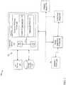
- FIG. 1 an illustrative environment 100 including an emissions prediction system 107 is shown according to embodiments of the invention.
- Environment 100 includes a computer infrastructure 102 that can perform the various processes described herein.
- computer infrastructure 102 is shown including computing device 110 which includes emissions prediction system 107, which enables computing device 110 to manage emissions sensitive transient state operation of a power generation system 140 by performing the process steps of the disclosure.
- emissions prediction system 107 has the beneficial effect of enabling computing device 110 to perform, among other things, the emissions sensitive control operations described herein. It is understood that some of the various components shown in FIG. 1 can be implemented independently, combined, and/or stored in memory for one or more separate computing devices that are included in computing device 110. Further, it is understood that some of the components and/or functionality may not be implemented, or additional schemas and/or functionality may be included as part of emissions prediction system 107.
- Computing device 110 is shown including a memory 112, a processor unit (PU) 114, an input/output (I/O) interface 116, and a bus 118. Further, computing device 110 is shown in communication with an external I/O device/resource 120 and a storage system 122.
- PU 114 executes computer program code, such as emissions prediction system 107, that is stored in memory 112 and/or storage system 122. While executing computer program code, PU 114 can read and/or write data, such as graphical user interface 130 and/or operational data 134, to/from memory 112, storage system 122, and/or I/O interface 116.
- Bus 118 provides a communications link between each of the components in computing device 110.
- I/O device 120 can comprise any device that enables a user to interact with computing device 110 or any device that enables computing device 110 to communicate with one or more other computing devices.
- Input/output devices (including but not limited to keyboards, displays, pointing devices, etc.) can be coupled to the system either directly or through intervening I/O controllers.
- environment 100 includes at least one component sensor 142, optionally includes at least one emissions sensor 144 and includes at least one ambient sensor 146 communicatively connected to power generation system 140 and computing device 110 (e.g., via wireless or hard-wired means).
- Component sensor 142, emissions sensor 144 and ambient sensor 146 may include any number of sensors as is known, including a thermometer, a barometer, a humidity sensing device, gas turbine instruments, steam turbine instruments, etc.
- computing device 110 and/or emissions prediction system 107 may be disposed upon or within power generation system 140.
- computing device 110 can comprise any general purpose computing article of manufacture capable of executing computer program code installed by a user (e.g., a personal computer, server, handheld device, etc.). However, it is understood that computing device 110 is only representative of various possible equivalent computing devices that may perform the various process steps of the disclosure. To this extent, in other embodiments, computing device 110 can comprise any specific purpose computing article of manufacture comprising hardware and/or computer program code for performing specific functions, any computing article of manufacture that comprises a combination of specific purpose and general purpose hardware/software, or the like. In each case, the program code and hardware can be created using standard programming and engineering techniques, respectively. In one embodiment, computing device 110 may be/include a distributed control system. In another embodiment, computing device 110 may be integral to a gas turbine. In another embodiment, computing device 110 may be a part of power generation system 140.
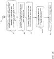
- emission prediction system 107 is initiated on computing device 110 to begin emissions sensitive steam temperature matching for transient state operation of power generation system 140. That is, either an automatic/scheduled adjustment to the operational steam temperature of power generation system 140, a condition dictated adjustment to the operational steam temperature of power generation system 140 or a manual/user-commanded adjustment of the steam temperature may be performed by computing device 110.
- computing device 110 obtains operational data for at least one component of power generation system 140. Operational data may be obtained from at least one of: memory 112, storage system 122, component sensor 142, emissions sensor 144 and/or ambient sensor 146.
- Operational data may include a temperature of the at least one component, a temperature of a steam turbine in power generation system 140, a set of system specifications for power generation system 140, a set of current ambient conditions at the power generation system 140, steam turbine stress, steam turbine expansion, steam turbine clearances etc.
- computing device 110 connects with memory 112 and/or storage system 122, to access prediction reference data (e.g. a look-up table, a pre-generated curve, steam turbine design basis, etc.), to determine the allowable steam temperature range based upon the operational data obtained from power generation system 140.
- prediction reference data e.g. a look-up table, a pre-generated curve, steam turbine design basis, etc.
- computing device 110 predicts emissions generation values for various steam temperatures and optionally corresponding gas turbine operating condition(s) within a selected gas turbine load or other operating parameter range.
- the range of the selected gas turbine operating condition(s) including but not necessarily limited to the determined allowable steam temperature range.
- computing device 110 and/or PU 114 may access any of: an emissions look-up table, a pre-generated emissions curve and/or stored emissions data.
- Computing device 110 and/or PU 114 may compare the allowable steam temperature, corresponding gas turbine operating parameter(s) range and/or operational data to data points in any of the emissions look-up table, the pre-generated emissions curve and/or stored data to generate emissions predictions for a set of temperatures and/or corresponding gas turbine operating parameter(s) ranges.
- the corresponding gas turbine operating parameter(s) ranges including but not limited to the allowable operational steam temperature range.
- Computing device 110 and/or PU 114 may input operational data and the allowable steam temperature range and/or a given temperature within the allowable steam temperature range into memory 112 and/or storage system 122 to obtain/generate emissions predictions for a set of temperatures within the allowable operational steam temperature range.
- computing device 110 displays the emissions predictions for the set of steam temperatures and/or corresponding gas turbine operating condition(s) within the allowable steam temperature range on a graphical user interface 130.
- computing device 110 may display the emissions predictions as a set of curves.
- computing device 110 may display the emissions predictions as a set of data points within a table.
- graphical user interface 130 may include other power generation system 140 or turbine parameters as would be valuable for operator guidance in system and/or power plant operation.
- a user selects and/or is prompted to select an emissions sensitive operational steam temperature and/or gas turbine operating condition, and, in response to a user selection, computing device 110 adjusts the gas turbine operating parameter(s) to substantially attain the emissions sensitive operational steam temperature and/or selected gas turbine operating condition.
- computing device 110 determines an emissions sensitive operational steam temperature for the power generation system. In one embodiment, computing device 110 determines the emissions sensitive operational steam temperature by accessing an emissions prediction reference data set on memory 112 and/or storage system 122. Computing device 110 compares the data points in the emissions prediction reference data set to the obtained operational data and the determined allowable operational steam temperature range.
- computing device 110 may compare emissions predictions for a set of operational steam temperatures to determine an emissions sensitive operational steam temperature. In any event, following P4B, in process P5B, computing device 110 adjusts the gas turbine operating parameter(s) to substantially attain the determined emissions sensitive operational steam temperature. In one embodiment, computing device 110 may automatically adjust the gas turbine operating parameter(s). In another embodiment, computing device 110 may prompt and await user approval before adjusting the gas turbine operating parameter(s). In any event, following either of P5A or P5B, in process P6, an operational steam flow is either introduced to the steam turbine or an already existing operational steam flow to the steam turbine is altered. The new or altered operational steam flow is introduced at a temperature substantially equivalent to the emissions sensitive temperature.
- computing device 110 monitors emissions generation and operational steam temperature of power generation system 140 via component sensor 142, emissions sensor 144, and ambient sensor 146.
- Component sensor 142, emissions sensor 144 and ambient sensor 146 may be disposed upon, within or in fluid communication with power generation system 140. It is understood that component sensor 142, emissions sensor 144 and ambient sensor 146 may comprise any number of similar or varied sensors (e.g. pressure sensor, temperature sensor, humidity sensor, etc.).
- Component sensor 142, emissions sensor 144 and ambient sensor 146 may record/read operational data (e.g. component temperature, atmospheric temperature, barometric pressure, humidity, etc.) and/or emissions data (e.g.
- computing device 110 updates any of memory 112, storage system 122 and/or power system data 134 based upon readings by any of component sensor 142, emissions sensor 144 and ambient sensor 146. In one embodiment, these real-time readings are used to update operational data 134 and existing emissions predictions. These readings are saved in any of memory 112 and storage system 122 to enhance future emissions predictions by computing device 110. In one embodiment, these readings are factored into future emissions predictions by computing device 110.
- computing device 110 analyzes the emissions readings (e.g., determining an accuracy of the emissions predictions, monitoring emissions levels, etc.). In one embodiment, computing device 110 continues to predict emissions and adjust the operational steam temperature and corresponding gas turbine operating parameter(s) to substantially minimize emissions.
- computing device 110 displays the real time emissions values obtained from sensor 142 and/or sensor 144 on graphical user interface 130.
- the real time emissions values may be displayed comparatively with the emissions predictions on graphical user interface 130.
- the real time emissions values may be factored into the emissions predictions to display updated emissions predictions on graphical user interface 130.
- a user monitors the real time emissions values and adjusted/updated emissions prediction values within the allowable operational steam temperature range on the graphical user interface 130. The user adjusts the operational steam temperature to attain an emissions sensitive operational steam temperature.
- computing device 110 may automatically maintain an emissions sensitive operational steam temperature. Following P10, in process P11, the emissions prediction system 107 is stopped.
- each block in the flowchart or block diagrams may represent a module, segment, or portion of code, which comprises one or more executable instructions for implementing the specified logical function(s).
- the functions noted in the block may occur out of the order noted in the FIGURES. For example, two blocks shown in succession may, in fact, be executed substantially concurrently, or the blocks may sometimes be executed in the reverse order, depending upon the functionality involved.
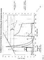
- UI 400 includes Steam Temperature curve (T S ), Gas turbine exhaust temperature curve (T G ), Emissions substance curve 1 (E1), Emissions substance curve 2 (E2), and Emissions substance curve 3 (E3).
- each emissions curve, E1, E2, and/or E3 may represent the predicted parts per million generation of a respective substance (Carbon monoxide, hydrocarbon, etc.) across a range of operating conditions.
- the predicted parts per million generation of a substance may be represented across a range of YO to Y10 parts per million.
- the emissions flow rate across a range of operating conditions may be displayed.
- E1, E2, and E3 are shown with respect to a range of gas turbine loads X0 through X10 and a range of Steam Turbine Component Temperatures Z0 through Z10.
- user interface 400 may include a graphically defined allowable steam temperature range R1 and a graphically defined allowable gas turbine load range R2.
- R1 and R2 may be calculated by computing device 110 and/or retrieved from a database.
- user interface 400 may include an Optimum Emissions Temperature Match (OETM) indicator, the OETM indicator for notifying a user/operator as to the load range of an emissions sensitive operational steam temperature.
- the operator may select the OETM indicator on user interface 400 to adjust the operational steam temperature. It is understood that user interface 400 is only an exemplary embodiment of the invention, other forms, formats and/or styles of user interfaces may be included as is known in the art.
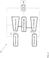
- Combined-cycle power plant 500 may include, for example, a gas turbine 580 operably connected to a generator 570.
- Generator 570 and gas turbine 580 may be mechanically coupled by a shaft 515, which may transfer energy between a gas turbine 580 and generator 570.
- a heat exchanger 586 operably connected to gas turbine 580 and a steam turbine 592.
- Heat exchanger 586 may be fluidly connected to both gas turbine 580 and steam turbine 592 via conventional conduits (numbering omitted).
- Heat exchanger 586 may be a conventional heat recovery steam generator (HRSG), such as those used in conventional combined-cycle power systems.
- HRSG heat recovery steam generator
- HRSG 586 may use hot exhaust from gas turbine 580, combined with a water supply, to create steam which is fed to steam turbine 592.
- Steam turbine 592 may optionally be coupled to a second generator system 570 (via a second shaft 515). Any of generator system 570, gas turbine 580, HRSG 586, and steam turbine 592 may be operably connected to emissions prediction system 107 via computing device 110 of FIG. 1 or other embodiments described herein. It is understood that generators 570 and shafts 515 may be of any size or type known in the art and may differ depending upon their application or the system to which they are connected. Common numbering of the generators and shafts is for clarity and does not necessarily suggest these generators or shafts are identical.
- Generator system 570 and second shaft 515 may operate substantially similarly to generator system 570 and shaft 515 described above.
- emissions prediction system 107 may be used, via computing device 110 to operate either or both of steam turbine 592 and gas turbine 580.
- a single-shaft combined-cycle power plant 600 may include a single generator 570 coupled to both gas turbine 580 and steam turbine 592 via a single shaft 515.
- Gas turbine 580 and steam turbine 592 may be operably connected to emissions prediction system 107 via computing device 110 of FIG. 1 or other embodiments described herein.
- the emissions prediction system of the present disclosure is not limited to any one power generation system, combined cycle power generation system, turbine or other system, and may be used with other power systems. Additionally, the system of the present invention may be used with other systems not described herein that may benefit from the emissions sensitive transient operation provided by the emission prediction system described herein.
- various systems and components are described as “obtaining” and/or “transferring” data (e.g., operational data, component temperatures, system specifications, etc.). It is understood that the corresponding data can be obtained using any solution.
- the corresponding system/component can generate and/or be used to generate the data, retrieve the data from one or more data stores or sensors (e.g., a database), receive the data from another system/component, and/or the like.
- the data is not generated by the particular system/component, it is understood that another system/component can be implemented apart from the system/component shown, which generates the data and provides it to the system/component and/or stores the data for access by the system/component.
Landscapes
- Engineering & Computer Science (AREA)
- Chemical & Material Sciences (AREA)
- Combustion & Propulsion (AREA)
- Mechanical Engineering (AREA)
- General Engineering & Computer Science (AREA)
- Physics & Mathematics (AREA)
- Thermal Sciences (AREA)
- Life Sciences & Earth Sciences (AREA)
- Sustainable Development (AREA)
- Sustainable Energy (AREA)
- Engine Equipment That Uses Special Cycles (AREA)
- Control Of Turbines (AREA)
Claims (13)
- Système comprenant :
au moins un dispositif informatique (102, 110, 114) conçu pour commander un système de production d'électricité (140, 500, 600) pour ajuster une température d'une vapeur opérationnelle dans le système de production d'électricité (140, 500, 600), le système comprenant des moyens d'obtenir des données opérationnelles (134), y compris une température des composants d'une turbine à vapeur (592) dans le système de production d'électricité et un ensemble de conditions ambiantes courantes, le système commandant le système de production d'électricité pour ajuster une température de vapeur opérationnelle par réalisation d'actions comprenant :l'obtention de données opérationnelles (134) en provenance des moyens d'obtenir des données opérationnelles (134), y compris des données opérationnelles concernant des composants d'une turbine à vapeur (592) dans le système de production d'électricité (140, 500, 600), les données opérationnelles (134) incluant une température des composants et un ensemble de conditions ambiantes courantes au niveau du système de production d'électricité (140, 500, 600) ;les moyens d'obtenir des données opérationnelles (134) incluant au moins un capteur de composant (142) et un capteur ambiant (146) et les actions comprenant l'obtention les données opérationnelles (134) en provenance desdits capteurs (142, 146),la détermination d'une plage de températures de vapeur opérationnelle admissibles (R1) pour la turbine à vapeur (592) sur la base des données opérationnelles (134) ;la génération de prédictions d'émissions (E1, E2, E3, OETM) pour un ensemble de températures à l'intérieur de la plage de températures de vapeur admissibles (R1) ; etla commande du système de production d'électricité pour ajuster la température de la vapeur opérationnelle sur la base des prédictions d'émissions (E1, E2, E3, OETM). - Système selon la revendication 1, dans lequel l'ajustement de la température de la vapeur opérationnelle inclut l'ajustement d'un paramètre de fonctionnement sur une turbine à gaz (580) dans le système de production d'électricité (140, 500, 600).
- Système selon la revendication 1 ou 2, dans lequel l'au moins un dispositif informatique (102, 110, 114) est en outre conçu pour afficher les prédictions d'émissions (E1, E2, E3, OETM) pour l'ensemble de températures à l'intérieur de la plage de températures de vapeur admissibles (R1) sur une interface utilisateur (130, 400).
- Système selon la revendication 3, dans lequel l'ajustement de la température de la vapeur opérationnelle inclut en outre :l'invitation d'un utilisateur à sélectionner ou à approuver une température de vapeur opérationnelle sensible aux émissions par l'intermédiaire de l'interface utilisateur (130, 400) ;la réception de la sélection ou de l'approbation de la température de vapeur opérationnelle sensible aux émissions provenant de l'utilisateur par l'intermédiaire de l'interface utilisateur (130, 400) ; etl'ajustement de la température de la vapeur opérationnelle afin d'atteindre sensiblement la température de vapeur opérationnelle sensible aux émissions.
- Système selon n'importe quelle revendication précédente, comprenant en outre un ensemble de capteurs d'émissions (142, 144, 146) connectés de manière communicante à l'au moins un dispositif informatique (102, 110, 114) et en communication fluidique avec le système de production d'électricité (140, 500, 600), l'ensemble de capteurs d'émissions (142, 144, 146) étant configuré pour surveiller des émissions du système de production d'électricité (140, 500, 600).
- Système selon la revendication 5, comprenant en outre une base de données (112, 122) connectée de manière communicante à l'ensemble de capteurs d'émissions (142, 144, 146) et au dispositif informatique (102, 110, 114), la base de données (112, 122) étant configurée pour stocker des mesures effectuées par les capteurs d'émissions (142, 144, 146).
- Système selon n'importe quelle revendication précédente, dans lequel l'ajustement de la température de la vapeur opérationnelle inclut en outre :la détermination d'une température de vapeur opérationnelle optimale (OETM) pour réduire les émissions sur la base des prédictions d'émissions (E1, E2, E3, OETM) ; etl'ajustement d'une charge sur une turbine à gaz (580) dans le système de production d'électricité (140, 500, 600) afin d'atteindre la température de vapeur opérationnelle optimale (OETM) déterminée.
- Système selon l'une quelconque des revendications précédentes, dans lequel le dispositif informatique (110) surveille la génération d'émissions et la température de vapeur opérationnelle du système de production d'électricité (140) par l'intermédiaire d'un capteur de composant (142), d'un capteur d'émissions (144) et d'un capteur ambiant (146).
- Produit programme stocké sur un support lisible par ordinateur (112, 122), qui, lorsqu'il est exécuté par au moins un dispositif informatique (102, 110, 114) d'un système selon l'une des revendications 1-8 pour commander un système de production d'électricité, le système comprenant des moyens d'obtenir des données opérationnelles (134), y compris une température des composants d'une turbine à vapeur (592) dans le système de production d'électricité et un ensemble de conditions ambiantes courantes, configure le système pour:obtenir des données opérationnelles (134) incluant des données opérationnelles concernant des composants d'une turbine à vapeur (592) dans un système de production d'électricité (140, 500, 600), les données opérationnelles (134) incluant une température des composants et un ensemble de conditions ambiantes courantes au niveau du système de production d'électricité (140, 500, 600);obtenir les données opérationnelles (134) en provenance d'un capteur de composant (142) et d'un capteur ambiant (146),déterminer une plage de températures de vapeur opérationnelle admissibles (R1) pour la turbine à vapeur (592) sur la base des données opérationnelles (134) ;générer des prédictions d'émissions (E1, E2, E3, OETM) pour un ensemble de températures à l'intérieur de la plage de températures de vapeur admissibles (R1) ; etcommander le système de production d'électricité pour ajuster la température d'une vapeur opérationnelle dans le système de production d'électricité (140, 500, 600) sur la base des prédictions d'émissions (E1, E2, E3, OETM).
- Système de production d'électricité à cycle combiné (140, 500, 600) comprenant :une turbine à gaz (580) ;un générateur de vapeur à récupération de chaleur (HRSG) (586) fonctionnellement raccordé à la turbine à gaz (580) ;une turbine à vapeur (592) fonctionnellement raccordée au HRSG (586) ;une génératrice (570) fonctionnellement raccordée à au moins une de la turbine à gaz (580) et de la turbine à vapeur (592) ; etun système selon l'une quelconque des revendications précédentes 1-8, dans lequel le système de production d'électricité est le système de production d'électricité à cycle combiné (140, 500, 600).
- Système de production d'électricité à cycle combiné selon la revendication précédente, dans lequel l'ajustement de la température de la vapeur opérationnelle inclut l'ajustement d'un paramètre de fonctionnement sur une turbine à gaz (580) dans le système de production d'électricité (140, 500, 600).
- Système de production d'électricité à cycle combiné (140, 500, 600) selon l'une quelconque des revendications précédentes revendiquant un système de production d'électricité à cycle combiné, dans lequel l'au moins un dispositif informatique (102, 110, 114) est en outre conçu pour afficher les prédictions d'émissions (E1, E2, E3, OETM) pour l'ensemble de températures à l'intérieur de la plage de températures de vapeur admissibles (R1) sur une interface utilisateur (130, 140).
- Système de production d'électricité à cycle combiné (140, 500, 600) selon la revendication précédente, dans lequel l'ajustement de la température de la vapeur opérationnelle inclut en outre :l'invitation d'un utilisateur à sélectionner ou à approuver une température de vapeur opérationnelle sensible aux émissions par l'intermédiaire de l'interface utilisateur (130, 400) ;la réception de la sélection ou de l'approbation de la température de vapeur opérationnelle sensible aux émissions provenant de l'utilisateur par l'intermédiaire de l'interface utilisateur (130, 400) ; etl'ajustement de la température de la vapeur opérationnelle afin d'atteindre sensiblement la température de vapeur opérationnelle sensible aux émissions.
Applications Claiming Priority (1)
| Application Number | Priority Date | Filing Date | Title |
|---|---|---|---|
| US13/214,915 US8567175B2 (en) | 2011-08-22 | 2011-08-22 | Emissions prediction system for power generation system |
Publications (3)
| Publication Number | Publication Date |
|---|---|
| EP2562371A2 EP2562371A2 (fr) | 2013-02-27 |
| EP2562371A3 EP2562371A3 (fr) | 2017-06-21 |
| EP2562371B1 true EP2562371B1 (fr) | 2020-03-11 |
Family
ID=47225918
Family Applications (1)
| Application Number | Title | Priority Date | Filing Date |
|---|---|---|---|
| EP12181227.5A Active EP2562371B1 (fr) | 2011-08-22 | 2012-08-21 | Système de prédiction d'émissions pour système de génération de puissance |
Country Status (5)
| Country | Link |
|---|---|
| US (1) | US8567175B2 (fr) |
| EP (1) | EP2562371B1 (fr) |
| JP (1) | JP6118048B2 (fr) |
| CN (1) | CN102955980B (fr) |
| BR (1) | BR102012020957A8 (fr) |
Families Citing this family (3)
| Publication number | Priority date | Publication date | Assignee | Title |
|---|---|---|---|---|
| US20150121888A1 (en) * | 2013-11-05 | 2015-05-07 | General Electric Company | Gas turbine online wash control |
| US9581086B2 (en) * | 2013-12-20 | 2017-02-28 | General Electric Company | Turbine operational flexibility |
| JP6266361B2 (ja) * | 2014-01-27 | 2018-01-24 | 三菱重工業株式会社 | 燃料供給装置、燃焼器、ガスタービン、及び燃料供給方法 |
Family Cites Families (14)
| Publication number | Priority date | Publication date | Assignee | Title |
|---|---|---|---|---|
| JPS5954711A (ja) * | 1982-09-24 | 1984-03-29 | Toshiba Corp | コンバインドサイクルタービンプラントの蒸気噴射制御装置 |
| US4473536A (en) * | 1982-12-27 | 1984-09-25 | General Electric Company | Catalytic pollution control system for gas turbine exhaust |
| JPS61104107A (ja) * | 1984-10-25 | 1986-05-22 | Hitachi Ltd | 発電プラントのNOx制御方法 |
| JPH0713472B2 (ja) * | 1985-01-25 | 1995-02-15 | 株式会社日立製作所 | タービンの運転制御方法、および複合サイクル原動機プラント |
| JPS64326A (en) * | 1987-06-23 | 1989-01-05 | Hitachi Ltd | Nox abating type gas turbine plant |
| JP3672339B2 (ja) * | 1994-05-16 | 2005-07-20 | 株式会社東芝 | 一軸型コンバインドサイクルプラントの起動方法及び起動装置 |
| JP3666036B2 (ja) * | 1994-11-04 | 2005-06-29 | 株式会社日立製作所 | 火力発電プラント起動制御システム及び起動制御方法 |
| US6644011B2 (en) * | 2000-03-24 | 2003-11-11 | Cheng Power Systems, Inc. | Advanced Cheng Combined Cycle |
| JP3858267B2 (ja) * | 2002-06-14 | 2006-12-13 | マツダ株式会社 | 排気浄化装置 |
| DE10310954A1 (de) * | 2003-03-13 | 2004-09-23 | Robert Bosch Gmbh | Verfahren zur Diagnose eines NOx-Sensors |
| US6978620B2 (en) | 2004-02-09 | 2005-12-27 | General Electric Company | Start-up method for power plant |
| US7756591B2 (en) * | 2006-04-25 | 2010-07-13 | Pegasus Technologies, Inc. | System for optimizing oxygen in a boiler |
| US8042340B2 (en) * | 2007-09-19 | 2011-10-25 | General Electric Company | Method and system for modulating the modified wobbe index of a fuel |
| US8352148B2 (en) | 2008-05-21 | 2013-01-08 | General Electric Company | System for controlling input profiles of combined cycle power generation system |
-
2011
- 2011-08-22 US US13/214,915 patent/US8567175B2/en active Active
-
2012
- 2012-08-17 JP JP2012180698A patent/JP6118048B2/ja active Active
- 2012-08-21 EP EP12181227.5A patent/EP2562371B1/fr active Active
- 2012-08-21 BR BR102012020957A patent/BR102012020957A8/pt not_active IP Right Cessation
- 2012-08-22 CN CN201210300122.3A patent/CN102955980B/zh not_active Expired - Fee Related
Non-Patent Citations (1)
| Title |
|---|
| None * |
Also Published As
| Publication number | Publication date |
|---|---|
| EP2562371A3 (fr) | 2017-06-21 |
| JP6118048B2 (ja) | 2017-04-19 |
| US8567175B2 (en) | 2013-10-29 |
| US20130047615A1 (en) | 2013-02-28 |
| JP2013044329A (ja) | 2013-03-04 |
| CN102955980A (zh) | 2013-03-06 |
| EP2562371A2 (fr) | 2013-02-27 |
| CN102955980B (zh) | 2018-05-25 |
| BR102012020957A8 (pt) | 2021-08-03 |
| BR102012020957A2 (pt) | 2013-11-12 |
Similar Documents
| Publication | Publication Date | Title |
|---|---|---|
| Tsoutsanis et al. | Dynamic performance simulation and control of gas turbines used for hybrid gas/wind energy applications | |
| US20140244055A1 (en) | Systems and methods for use in adapting the operation of a gas turbine | |
| EP2256320B1 (fr) | Systèmes et procédés de contrôle de débit de carburant sur un composant de turbine | |
| JP2009008078A (ja) | マルチ缶型燃焼器に対して燃焼ダイナミックス調整アルゴリズムを用いるためのシステム及び方法 | |
| JP2005284388A (ja) | プラントの運転スケジュール最適化方法および最適化システム | |
| EP2599971B1 (fr) | Systèmes de génération de vapeur et procédés pour commander leur fonctionnement | |
| JP2009008077A (ja) | マルチ缶型燃焼器に対して燃焼ダイナミックス調整アルゴリズムを用いるためのシステム及び方法 | |
| JP6037448B2 (ja) | 蒸気タービン発電プラント | |
| EP3064746B1 (fr) | Systèmes et procédés de fonctionnement d'un système de turbine à faibles températures ambiantes | |
| US10006315B2 (en) | System and method for improved control of a combined cycle power plant | |
| EP2562371B1 (fr) | Système de prédiction d'émissions pour système de génération de puissance | |
| US20180284748A1 (en) | Control systems and methods for controlling power systems based on operational reliabilities and operational anomalies | |
| JP2014196715A (ja) | 蒸気タービン発電プラント | |
| JPWO2015193979A1 (ja) | 多軸可変速ガスタービン装置およびその制御方法 | |
| US20110146288A1 (en) | Method of controlling a fuel flow to a turbomachine | |
| US9639071B2 (en) | Method and system for combustion mode transfer for a gas turbine engine | |
| JP2016023604A (ja) | 温度推定装置、燃焼器、ガスタービン、温度推定方法及びプログラム | |
| EP3121392B1 (fr) | Dispositif de commande de démarrage et procédé de commande de démarrage pour centrale électrique | |
| Zaccaria et al. | Adaptive control of microgas turbine for engine degradation compensation | |
| EP2339127A2 (fr) | Procédé de démarrage d'une turbomachine | |
| US9500136B2 (en) | Systems and methods for generating variable ramp rates for turbomachinery | |
| JP2007138856A (ja) | 蒸気タービンプラントの起動スケジュール予測システムおよび予測方法、ならびに予測用プログラムおよび該プログラムを格納した記録媒体 | |
| Tsai et al. | Adaptive control of a nonlinear fuel cell-gas turbine balance of plant simulation facility | |
| US8925319B2 (en) | Steam flow control system | |
| US9464534B2 (en) | Turbine purge flow control system and related method of operation |
Legal Events
| Date | Code | Title | Description |
|---|---|---|---|
| PUAI | Public reference made under article 153(3) epc to a published international application that has entered the european phase |
Free format text: ORIGINAL CODE: 0009012 |
|
| AK | Designated contracting states |
Kind code of ref document: A2 Designated state(s): AL AT BE BG CH CY CZ DE DK EE ES FI FR GB GR HR HU IE IS IT LI LT LU LV MC MK MT NL NO PL PT RO RS SE SI SK SM TR |
|
| AX | Request for extension of the european patent |
Extension state: BA ME |
|
| PUAL | Search report despatched |
Free format text: ORIGINAL CODE: 0009013 |
|
| AK | Designated contracting states |
Kind code of ref document: A3 Designated state(s): AL AT BE BG CH CY CZ DE DK EE ES FI FR GB GR HR HU IE IS IT LI LT LU LV MC MK MT NL NO PL PT RO RS SE SI SK SM TR |
|
| AX | Request for extension of the european patent |
Extension state: BA ME |
|
| RIC1 | Information provided on ipc code assigned before grant |
Ipc: G05B 13/04 20060101ALI20170518BHEP Ipc: F22B 35/00 20060101ALI20170518BHEP Ipc: F22B 35/18 20060101ALI20170518BHEP Ipc: F01K 23/10 20060101ALI20170518BHEP Ipc: F01K 7/00 20060101AFI20170518BHEP Ipc: F22B 1/18 20060101ALI20170518BHEP |
|
| STAA | Information on the status of an ep patent application or granted ep patent |
Free format text: STATUS: REQUEST FOR EXAMINATION WAS MADE |
|
| 17P | Request for examination filed |
Effective date: 20171221 |
|
| RBV | Designated contracting states (corrected) |
Designated state(s): AL AT BE BG CH CY CZ DE DK EE ES FI FR GB GR HR HU IE IS IT LI LT LU LV MC MK MT NL NO PL PT RO RS SE SI SK SM TR |
|
| GRAP | Despatch of communication of intention to grant a patent |
Free format text: ORIGINAL CODE: EPIDOSNIGR1 |
|
| STAA | Information on the status of an ep patent application or granted ep patent |
Free format text: STATUS: GRANT OF PATENT IS INTENDED |
|
| INTG | Intention to grant announced |
Effective date: 20190417 |
|
| GRAJ | Information related to disapproval of communication of intention to grant by the applicant or resumption of examination proceedings by the epo deleted |
Free format text: ORIGINAL CODE: EPIDOSDIGR1 |
|
| STAA | Information on the status of an ep patent application or granted ep patent |
Free format text: STATUS: REQUEST FOR EXAMINATION WAS MADE |
|
| INTC | Intention to grant announced (deleted) | ||
| GRAS | Grant fee paid |
Free format text: ORIGINAL CODE: EPIDOSNIGR3 |
|
| STAA | Information on the status of an ep patent application or granted ep patent |
Free format text: STATUS: GRANT OF PATENT IS INTENDED |
|
| GRAP | Despatch of communication of intention to grant a patent |
Free format text: ORIGINAL CODE: EPIDOSNIGR1 |
|
| INTG | Intention to grant announced |
Effective date: 20191015 |
|
| GRAA | (expected) grant |
Free format text: ORIGINAL CODE: 0009210 |
|
| STAA | Information on the status of an ep patent application or granted ep patent |
Free format text: STATUS: THE PATENT HAS BEEN GRANTED |
|
| AK | Designated contracting states |
Kind code of ref document: B1 Designated state(s): AL AT BE BG CH CY CZ DE DK EE ES FI FR GB GR HR HU IE IS IT LI LT LU LV MC MK MT NL NO PL PT RO RS SE SI SK SM TR |
|
| REG | Reference to a national code |
Ref country code: GB Ref legal event code: FG4D |
|
| REG | Reference to a national code |
Ref country code: CH Ref legal event code: EP |
|
| REG | Reference to a national code |
Ref country code: AT Ref legal event code: REF Ref document number: 1243388 Country of ref document: AT Kind code of ref document: T Effective date: 20200315 |
|
| REG | Reference to a national code |
Ref country code: IE Ref legal event code: FG4D |
|
| REG | Reference to a national code |
Ref country code: DE Ref legal event code: R096 Ref document number: 602012068357 Country of ref document: DE |
|
| PG25 | Lapsed in a contracting state [announced via postgrant information from national office to epo] |
Ref country code: NO Free format text: LAPSE BECAUSE OF FAILURE TO SUBMIT A TRANSLATION OF THE DESCRIPTION OR TO PAY THE FEE WITHIN THE PRESCRIBED TIME-LIMIT Effective date: 20200611 Ref country code: RS Free format text: LAPSE BECAUSE OF FAILURE TO SUBMIT A TRANSLATION OF THE DESCRIPTION OR TO PAY THE FEE WITHIN THE PRESCRIBED TIME-LIMIT Effective date: 20200311 Ref country code: FI Free format text: LAPSE BECAUSE OF FAILURE TO SUBMIT A TRANSLATION OF THE DESCRIPTION OR TO PAY THE FEE WITHIN THE PRESCRIBED TIME-LIMIT Effective date: 20200311 |
|
| REG | Reference to a national code |
Ref country code: NL Ref legal event code: MP Effective date: 20200311 |
|
| PG25 | Lapsed in a contracting state [announced via postgrant information from national office to epo] |
Ref country code: GR Free format text: LAPSE BECAUSE OF FAILURE TO SUBMIT A TRANSLATION OF THE DESCRIPTION OR TO PAY THE FEE WITHIN THE PRESCRIBED TIME-LIMIT Effective date: 20200612 Ref country code: HR Free format text: LAPSE BECAUSE OF FAILURE TO SUBMIT A TRANSLATION OF THE DESCRIPTION OR TO PAY THE FEE WITHIN THE PRESCRIBED TIME-LIMIT Effective date: 20200311 Ref country code: LV Free format text: LAPSE BECAUSE OF FAILURE TO SUBMIT A TRANSLATION OF THE DESCRIPTION OR TO PAY THE FEE WITHIN THE PRESCRIBED TIME-LIMIT Effective date: 20200311 Ref country code: SE Free format text: LAPSE BECAUSE OF FAILURE TO SUBMIT A TRANSLATION OF THE DESCRIPTION OR TO PAY THE FEE WITHIN THE PRESCRIBED TIME-LIMIT Effective date: 20200311 Ref country code: BG Free format text: LAPSE BECAUSE OF FAILURE TO SUBMIT A TRANSLATION OF THE DESCRIPTION OR TO PAY THE FEE WITHIN THE PRESCRIBED TIME-LIMIT Effective date: 20200611 |
|
| REG | Reference to a national code |
Ref country code: LT Ref legal event code: MG4D |
|
| PG25 | Lapsed in a contracting state [announced via postgrant information from national office to epo] |
Ref country code: NL Free format text: LAPSE BECAUSE OF FAILURE TO SUBMIT A TRANSLATION OF THE DESCRIPTION OR TO PAY THE FEE WITHIN THE PRESCRIBED TIME-LIMIT Effective date: 20200311 |
|
| PG25 | Lapsed in a contracting state [announced via postgrant information from national office to epo] |
Ref country code: LT Free format text: LAPSE BECAUSE OF FAILURE TO SUBMIT A TRANSLATION OF THE DESCRIPTION OR TO PAY THE FEE WITHIN THE PRESCRIBED TIME-LIMIT Effective date: 20200311 Ref country code: CZ Free format text: LAPSE BECAUSE OF FAILURE TO SUBMIT A TRANSLATION OF THE DESCRIPTION OR TO PAY THE FEE WITHIN THE PRESCRIBED TIME-LIMIT Effective date: 20200311 Ref country code: RO Free format text: LAPSE BECAUSE OF FAILURE TO SUBMIT A TRANSLATION OF THE DESCRIPTION OR TO PAY THE FEE WITHIN THE PRESCRIBED TIME-LIMIT Effective date: 20200311 Ref country code: SK Free format text: LAPSE BECAUSE OF FAILURE TO SUBMIT A TRANSLATION OF THE DESCRIPTION OR TO PAY THE FEE WITHIN THE PRESCRIBED TIME-LIMIT Effective date: 20200311 Ref country code: EE Free format text: LAPSE BECAUSE OF FAILURE TO SUBMIT A TRANSLATION OF THE DESCRIPTION OR TO PAY THE FEE WITHIN THE PRESCRIBED TIME-LIMIT Effective date: 20200311 Ref country code: SM Free format text: LAPSE BECAUSE OF FAILURE TO SUBMIT A TRANSLATION OF THE DESCRIPTION OR TO PAY THE FEE WITHIN THE PRESCRIBED TIME-LIMIT Effective date: 20200311 Ref country code: PT Free format text: LAPSE BECAUSE OF FAILURE TO SUBMIT A TRANSLATION OF THE DESCRIPTION OR TO PAY THE FEE WITHIN THE PRESCRIBED TIME-LIMIT Effective date: 20200805 Ref country code: IS Free format text: LAPSE BECAUSE OF FAILURE TO SUBMIT A TRANSLATION OF THE DESCRIPTION OR TO PAY THE FEE WITHIN THE PRESCRIBED TIME-LIMIT Effective date: 20200711 |
|
| REG | Reference to a national code |
Ref country code: AT Ref legal event code: MK05 Ref document number: 1243388 Country of ref document: AT Kind code of ref document: T Effective date: 20200311 |
|
| REG | Reference to a national code |
Ref country code: DE Ref legal event code: R097 Ref document number: 602012068357 Country of ref document: DE |
|
| PLBE | No opposition filed within time limit |
Free format text: ORIGINAL CODE: 0009261 |
|
| STAA | Information on the status of an ep patent application or granted ep patent |
Free format text: STATUS: NO OPPOSITION FILED WITHIN TIME LIMIT |
|
| PG25 | Lapsed in a contracting state [announced via postgrant information from national office to epo] |
Ref country code: IT Free format text: LAPSE BECAUSE OF FAILURE TO SUBMIT A TRANSLATION OF THE DESCRIPTION OR TO PAY THE FEE WITHIN THE PRESCRIBED TIME-LIMIT Effective date: 20200311 Ref country code: ES Free format text: LAPSE BECAUSE OF FAILURE TO SUBMIT A TRANSLATION OF THE DESCRIPTION OR TO PAY THE FEE WITHIN THE PRESCRIBED TIME-LIMIT Effective date: 20200311 Ref country code: AT Free format text: LAPSE BECAUSE OF FAILURE TO SUBMIT A TRANSLATION OF THE DESCRIPTION OR TO PAY THE FEE WITHIN THE PRESCRIBED TIME-LIMIT Effective date: 20200311 Ref country code: DK Free format text: LAPSE BECAUSE OF FAILURE TO SUBMIT A TRANSLATION OF THE DESCRIPTION OR TO PAY THE FEE WITHIN THE PRESCRIBED TIME-LIMIT Effective date: 20200311 |
|
| 26N | No opposition filed |
Effective date: 20201214 |
|
| PG25 | Lapsed in a contracting state [announced via postgrant information from national office to epo] |
Ref country code: SI Free format text: LAPSE BECAUSE OF FAILURE TO SUBMIT A TRANSLATION OF THE DESCRIPTION OR TO PAY THE FEE WITHIN THE PRESCRIBED TIME-LIMIT Effective date: 20200311 Ref country code: PL Free format text: LAPSE BECAUSE OF FAILURE TO SUBMIT A TRANSLATION OF THE DESCRIPTION OR TO PAY THE FEE WITHIN THE PRESCRIBED TIME-LIMIT Effective date: 20200311 |
|
| PG25 | Lapsed in a contracting state [announced via postgrant information from national office to epo] |
Ref country code: MC Free format text: LAPSE BECAUSE OF FAILURE TO SUBMIT A TRANSLATION OF THE DESCRIPTION OR TO PAY THE FEE WITHIN THE PRESCRIBED TIME-LIMIT Effective date: 20200311 |
|
| REG | Reference to a national code |
Ref country code: CH Ref legal event code: PL |
|
| GBPC | Gb: european patent ceased through non-payment of renewal fee |
Effective date: 20200821 |
|
| PG25 | Lapsed in a contracting state [announced via postgrant information from national office to epo] |
Ref country code: CH Free format text: LAPSE BECAUSE OF NON-PAYMENT OF DUE FEES Effective date: 20200831 Ref country code: LI Free format text: LAPSE BECAUSE OF NON-PAYMENT OF DUE FEES Effective date: 20200831 Ref country code: LU Free format text: LAPSE BECAUSE OF NON-PAYMENT OF DUE FEES Effective date: 20200821 |
|
| REG | Reference to a national code |
Ref country code: BE Ref legal event code: MM Effective date: 20200831 |
|
| PG25 | Lapsed in a contracting state [announced via postgrant information from national office to epo] |
Ref country code: FR Free format text: LAPSE BECAUSE OF NON-PAYMENT OF DUE FEES Effective date: 20200831 |
|
| PG25 | Lapsed in a contracting state [announced via postgrant information from national office to epo] |
Ref country code: BE Free format text: LAPSE BECAUSE OF NON-PAYMENT OF DUE FEES Effective date: 20200831 Ref country code: GB Free format text: LAPSE BECAUSE OF NON-PAYMENT OF DUE FEES Effective date: 20200821 Ref country code: IE Free format text: LAPSE BECAUSE OF NON-PAYMENT OF DUE FEES Effective date: 20200821 |
|
| PG25 | Lapsed in a contracting state [announced via postgrant information from national office to epo] |
Ref country code: TR Free format text: LAPSE BECAUSE OF FAILURE TO SUBMIT A TRANSLATION OF THE DESCRIPTION OR TO PAY THE FEE WITHIN THE PRESCRIBED TIME-LIMIT Effective date: 20200311 Ref country code: MT Free format text: LAPSE BECAUSE OF FAILURE TO SUBMIT A TRANSLATION OF THE DESCRIPTION OR TO PAY THE FEE WITHIN THE PRESCRIBED TIME-LIMIT Effective date: 20200311 Ref country code: CY Free format text: LAPSE BECAUSE OF FAILURE TO SUBMIT A TRANSLATION OF THE DESCRIPTION OR TO PAY THE FEE WITHIN THE PRESCRIBED TIME-LIMIT Effective date: 20200311 |
|
| PG25 | Lapsed in a contracting state [announced via postgrant information from national office to epo] |
Ref country code: MK Free format text: LAPSE BECAUSE OF FAILURE TO SUBMIT A TRANSLATION OF THE DESCRIPTION OR TO PAY THE FEE WITHIN THE PRESCRIBED TIME-LIMIT Effective date: 20200311 Ref country code: AL Free format text: LAPSE BECAUSE OF FAILURE TO SUBMIT A TRANSLATION OF THE DESCRIPTION OR TO PAY THE FEE WITHIN THE PRESCRIBED TIME-LIMIT Effective date: 20200311 |
|
| REG | Reference to a national code |
Ref country code: DE Ref legal event code: R082 Ref document number: 602012068357 Country of ref document: DE Ref country code: DE Ref legal event code: R081 Ref document number: 602012068357 Country of ref document: DE Owner name: GENERAL ELECTRIC TECHNOLOGY GMBH, CH Free format text: FORMER OWNER: GENERAL ELECTRIC COMPANY, SCHENECTADY, NY, US |
|
| PGFP | Annual fee paid to national office [announced via postgrant information from national office to epo] |
Ref country code: DE Payment date: 20230720 Year of fee payment: 12 |