EP2561602B1 - Drillvorrichtung zum simultanen drehen mehrerer elektrischer stableiter zur herstellung einer stator- oder rotorwicklung für eine elektromaschine und extraktoranordnung zur kooperation mit dieser drillvorrichtung - Google Patents
Drillvorrichtung zum simultanen drehen mehrerer elektrischer stableiter zur herstellung einer stator- oder rotorwicklung für eine elektromaschine und extraktoranordnung zur kooperation mit dieser drillvorrichtung Download PDFInfo
- Publication number
- EP2561602B1 EP2561602B1 EP10726316.2A EP10726316A EP2561602B1 EP 2561602 B1 EP2561602 B1 EP 2561602B1 EP 10726316 A EP10726316 A EP 10726316A EP 2561602 B1 EP2561602 B1 EP 2561602B1
- Authority
- EP
- European Patent Office
- Prior art keywords
- channel
- groove
- twisting device
- array
- twisting
- Prior art date
- Legal status (The legal status is an assumption and is not a legal conclusion. Google has not performed a legal analysis and makes no representation as to the accuracy of the status listed.)
- Active
Links
Images



Classifications
-
- H—ELECTRICITY
- H02—GENERATION; CONVERSION OR DISTRIBUTION OF ELECTRIC POWER
- H02K—DYNAMO-ELECTRIC MACHINES
- H02K15/00—Processes or apparatus specially adapted for manufacturing, assembling, maintaining or repairing of dynamo-electric machines
- H02K15/04—Processes or apparatus specially adapted for manufacturing, assembling, maintaining or repairing of dynamo-electric machines of windings prior to their mounting into the machines
- H02K15/043—Processes or apparatus specially adapted for manufacturing, assembling, maintaining or repairing of dynamo-electric machines of windings prior to their mounting into the machines winding flat conductive wires or sheets
- H02K15/0431—Concentrated windings
-
- H—ELECTRICITY
- H02—GENERATION; CONVERSION OR DISTRIBUTION OF ELECTRIC POWER
- H02K—DYNAMO-ELECTRIC MACHINES
- H02K15/00—Processes or apparatus specially adapted for manufacturing, assembling, maintaining or repairing of dynamo-electric machines
- H02K15/04—Processes or apparatus specially adapted for manufacturing, assembling, maintaining or repairing of dynamo-electric machines of windings prior to their mounting into the machines
- H02K15/0414—Processes or apparatus specially adapted for manufacturing, assembling, maintaining or repairing of dynamo-electric machines of windings prior to their mounting into the machines the windings consisting of separate elements, e.g. bars, segments or half coils
- H02K15/0421—Processes or apparatus specially adapted for manufacturing, assembling, maintaining or repairing of dynamo-electric machines of windings prior to their mounting into the machines the windings consisting of separate elements, e.g. bars, segments or half coils and consisting of single conductors, e.g. hairpins
- H02K15/0428—Processes or apparatus for simultaneously twisting two or more hairpins
-
- G—PHYSICS
- G06—COMPUTING OR CALCULATING; COUNTING
- G06Q—INFORMATION AND COMMUNICATION TECHNOLOGY [ICT] SPECIALLY ADAPTED FOR ADMINISTRATIVE, COMMERCIAL, FINANCIAL, MANAGERIAL OR SUPERVISORY PURPOSES; SYSTEMS OR METHODS SPECIALLY ADAPTED FOR ADMINISTRATIVE, COMMERCIAL, FINANCIAL, MANAGERIAL OR SUPERVISORY PURPOSES, NOT OTHERWISE PROVIDED FOR
- G06Q50/00—Information and communication technology [ICT] specially adapted for implementation of business processes of specific business sectors, e.g. utilities or tourism
- G06Q50/04—Manufacturing
-
- H—ELECTRICITY
- H02—GENERATION; CONVERSION OR DISTRIBUTION OF ELECTRIC POWER
- H02K—DYNAMO-ELECTRIC MACHINES
- H02K1/00—Details of the magnetic circuit
- H02K1/06—Details of the magnetic circuit characterised by the shape, form or construction
- H02K1/12—Stationary parts of the magnetic circuit
- H02K1/16—Stator cores with slots for windings
- H02K1/165—Shape, form or location of the slots
-
- H—ELECTRICITY
- H02—GENERATION; CONVERSION OR DISTRIBUTION OF ELECTRIC POWER
- H02K—DYNAMO-ELECTRIC MACHINES
- H02K15/00—Processes or apparatus specially adapted for manufacturing, assembling, maintaining or repairing of dynamo-electric machines
- H02K15/04—Processes or apparatus specially adapted for manufacturing, assembling, maintaining or repairing of dynamo-electric machines of windings prior to their mounting into the machines
-
- Y—GENERAL TAGGING OF NEW TECHNOLOGICAL DEVELOPMENTS; GENERAL TAGGING OF CROSS-SECTIONAL TECHNOLOGIES SPANNING OVER SEVERAL SECTIONS OF THE IPC; TECHNICAL SUBJECTS COVERED BY FORMER USPC CROSS-REFERENCE ART COLLECTIONS [XRACs] AND DIGESTS
- Y10—TECHNICAL SUBJECTS COVERED BY FORMER USPC
- Y10T—TECHNICAL SUBJECTS COVERED BY FORMER US CLASSIFICATION
- Y10T29/00—Metal working
- Y10T29/49—Method of mechanical manufacture
- Y10T29/49002—Electrical device making
- Y10T29/49009—Dynamoelectric machine
- Y10T29/49012—Rotor
Definitions
- the present description refers to a twisting device suitable for simultaneously twisting a plurality of bar electric conductors for making a stator or rotor winding of an electric machine.
- the present description also refers to an extractor assembly suitable for cooperating with such a twisting device.
- stators or rotors for electric machines having a stator/rotor core in which a plurality of slots are provided and also comprising a plurality of bar electric conductors inserted into the aforementioned slots and variously interconnected with one another to form one or more stator/rotor windings.
- the aforementioned stator/rotor windings with bar conductors are commonly called bar stator/rotor windings.
- a twisting device is known to be used, at least in a partially automated manner, suitable for shaping the stator/rotor winding conductors from preformed or bent bar conductors, each having a first and a second arm arranged relatively close to one another or arranged side by side.
- the known twisting device comprises at least one first body extending around a twisting axis and at least one second body extending around the first body and coaxial with this latter.
- Such a first and second body are provided with a first and a second circular array of channels, respectively, having centre on the twisting axis.
- a plurality of the aforementioned bar conductors is inserted through a face of the twisting device in the channels provided on the first and on the second body. More in particular, the arms of each bar conductor are inserted into a channel of the first array and in a channel of the second array, respectively.
- the first and/or the second body are set in rotation around the twisting axis to separate the arms of each bar conductor from one another by an amount equal to a predetermined number of stator or rotor slots.
- the winding conductors thus formed are at least partially extracted from the twisting device and finally removed from it through a suitable clamp assembly to subsequently be arranged in the respective slots of the stator or rotor core.
- an extractor assembly is typically used situated directly below the twisting device.
- the extractor assembly comprises a first and a second circular array of extraction elements or extraction bars, which are arranged angularly and axially aligned to the channels of the first and of the second body of the twisting device, respectively.
- Such extraction bars can be moved from the bottom upwards through actuators so that the respective upper end portions can be inserted into the channels of the twisting device so as to lift the winding conductors.
- a twisting device, an extractor assembly and a clamp assembly of the aforementioned type are described for example in the patent application published as US 2009/0265909 .
- the present description has the purpose of providing a twisting device of the aforementioned type which makes it possible to satisfy the aforementioned need.
- An apparatus for making a stator or rotor pack of an electric machine as defined in the attached claim 15 is also an object of the present invention.
- the words “flat” or “square” or equivalent words used to describe the cross section of a bar conductor are used with a general meaning and must not be interpreted to exclude the fact that such bar conductors have significantly rounded corners which join the substantially flat sides.
- the expression “flat conductor” should be taken in the sense that the conductor has two opposite sides the distance of which is greater with respect to the distance between the remaining two opposite sides.
- the expression “rectangular conductor” should be taken as a generalisation of a flat conductor and of a square conductor, since the square conductor is a special case of rectangular conductor, in which the four sides have the same size.
- Figure 1 represents in general an apparatus 1 comprising a plurality of working stations 2, 3, 4, for making a stator or rotor pack of an electric machine.
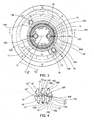
- a currently preferred embodiment of a bar electric conductor twisting device 10 is illustrated, suitable for being used in the apparatus 1.
- the twisting device 10 is suitable for simultaneously twisting a plurality of bar electric conductors 11 (only one of which is represented in figure 2 ) to make stator or rotor winding conductors for an electric machine (not represented), such as an electric generator or an electric motor.
- the twisting device is fixed to a rotating table 5 of the apparatus 1 through which it can subsequently be brought respectively into a loading station 2 so that the bar conductors can be forcibly inserted into the twisting device, into a twisting station 3 for shaping such conductors, and into an extraction station 4 for extracting and removing the shaped bar conductors from the twisting device, and inserting these into a stator or rotor pack (not represented).
- bar conductors which are substantially "U”-shaped or "P"-shaped so as to have a bent portion 11A joined to a first and to a second arm 11B, 11C relatively close to one another or arranged side by side and ending with respective free end portions 11D, 11E.
- the bar conductors 11 are covered on their surface with an insulation lining made from insulating material, like, for example, a enamel made from insulation resin.
- the device 10 comprises at least one first and one second body 12, 13 extending around a twisting axis Z-Z.
- the first body 12 or inner body 12 comprises a central portion 12A and a substantially sleeve-shaped peripheral portion 12B.
- a first pair of holes 12C or inner holes 12C is provided on the central portion 12A.
- the body 12 is provided with a first circular array of channels 15, or inner array, having its centre on the twisting axis Z-Z.
- the second body 13 or outer body 13 extends around the inner body 12 and is coaxial with it.
- the outer body has a generally tubular shape and it is provided with two manoeuvring portions 13A projecting outwards from two diametrically opposite sides of such a body.
- a second pair of holes 13B or outer holes 13B are provided, in particular one hole 13B on each manoeuvring portion.
- the outer body 13 is provided with a second circular array of channels 16, or outer array, having its centre on the twisting axis Z-Z.
- a channel 15 or inner channel 15 of the inner array and a channel 16 or outer channel 16 of the outer array can be placed side by side and aligned radially to one another to receive the first arm 11B and the second arm 11C of one same bar conductor 11, respectively.
- radial and circumferential refer to a generic circumference lying on a plane perpendicular to the twisting axis and having centre on such an axis.
- An example of radial and circumferential direction is indicated by the arrows RR and CC in figure 3 , respectively.
- a channel of the inner array and a channel of the outer array should be considered aligned radially if the sections of such channels lying on a plane perpendicular to the twisting axis comprise respective channel axes aligned radially to one another.
- the inner body and/or the outer body can be set in rotation around the twisting axis to move the arms 11B, 11C away from one another by a predetermined amount, normally by a quantity equal to a predetermined number of stator or rotor slots.
- the inner and outer bodies are preferably adapted to be set in rotation in opposite directions around the twisting axis. Generally, however, it is sufficient to have a relative rotation in opposite directions between such bodies to carry out the twisting operation.
- the inner body for example, could be kept fixed and the outer body could be set in rotation or vice versa, the outer body could be kept fixed and the inner body could be set in rotation.
- the setting of the inner and outer bodies in rotation is carried out by means of a device (not represented since it is known by a man skilled in the art) including a pair of inner actuation bars and a pair of outer actuation bars, which can engage into the aforementioned inner and outer holes 12C, 13B, respectively, and can be set in rotation so as to pull the inner and outer bodies in rotation, preferably in opposite directions.
- each of the inner channels 15 a channel extension groove 15A is formed extending longitudinally in a direction parallel to the twisting axis and projecting from the respective channel in a direction which is circumferential with respect to the twisting axis.
- the device 10 comprises a plurality of longitudinal grooves 15A formed in the inner body, each of which communicates with an associated inner,channel 15 along the axial extension of such a channel and projects from the latter in a circumferential direction.
- each groove 15A is suitable for remaining empty when an arm of the bar conductor 11, for example, the arm 11B, is received in the channel from which such a groove projects.
- the grooves 15A extend along a prevalent axial extension portion of the respective channels. Even more preferably, the grooves 15A extend along the entire axial extension of the respective channels so as to pass the inner body from one end to the other.
- each channel 15 is defined by channel walls 15B, 15C, 15D, 15E, 15F. It should be observed that in the currently preferred embodiment illustrated in the figures, the channel wall 15F is not present. In other words according to such an embodiment each of the channels 15 has a respective open side. However, for the sake of making the description more complete, in the present description the channels 15F shall generally be considered as being defined also by the wall 15F, unless specified otherwise. It should be observed that the wall 15B opposite the groove 15A is conveniently a thrust wall.
- the wall 15B which is preferably a flat wall, is suitable for engaging with a face of the arm 11B inserted into the channel 15 so as to exert a thrust action, on such an arm, in the rotation direction of such a channel, i.e. in the rotation direction of the inner body, when such a body is set in rotation to twist the bar conductors 11.
- Each inner channel 15 includes at least one pair of opposite holding walls 15B, 15D, 15E suitable for simultaneously engaging with an arm of the bar conductor 11 housed in such a channel on two respective opposite sides, in the example the arm 11B.
- opposite holding walls include the thrust wall 15B.
- the holding walls 15B, 15D, 15E extend in a radial direction whereas the opposite channel walls 15C, 15F extend in a circumferential direction.
- the opposite holding walls 15B, 15D, 15E are relatively closer to one another, whereas the opposite channel walls 15C, 15F are relatively farther away from one another.
- the groove 15A is also defined by at least one groove wall joined to at least one of the opposing holding walls 15B, 15D, 15E.
- the groove 15A is defined by a plurality of groove walls 15', 15", 15"'.
- such walls comprise a pair of opposite groove walls 15', 15" extending in a circumferential direction and an intermediate groove wall 15"' joined to the walls 15', 15" and extending in a radial direction.
- the groove walls 15', 15", 15"' it could be provided for there to be, for example, a single concave groove wall having its concavity facing the channel 15.
- each groove 15A and the respective channel 15 have a radial extension defined by at least one of the groove walls 15', 15", 15"', and by at least one of the channel walls 15B, 15C, 15D, 15E, 15F, respectively.
- the radial extension of the groove is defined by the walls 15', 15" whereas the radial extension of the associated channel is defined by the channel walls 15C, 15F.
- the radial extension of the groove 15A is relatively smaller than the radial extension of the respective channel 15.
- each groove is radially offset with respect to the channel 15 from which it projects.
- each groove 15A is radially offset towards an annular clearance 18 or separation gap 18 extending between the inner body and the outer body.
- at least one separation element or separation sleeve (not represented in the figures) is housed placed between the channels 15 of the inner array and the channels 16 of the outer array.
- the channels 15 do not have the wall 15F and in which, therefore, such portions of the inner body are essentially cantilevered portions intended to undergo bending stress during the twisting operation.
- the channel walls 15B, 15C, 15D, 15E, 15F of each inner channel 15 and the groove walls 15', 15'', 15''' of the groove 15A projecting from such a channel have a profile of the section perpendicular to the twisting axis which is suitable for defining generally an opening 15G.
- the opening 15G is substantially T-shaped, in which the leg of the T corresponds to the groove 15A and the cross end of the T, joined to the leg, corresponds to the channel 15.
- the leg of the T is relatively shorter than the cross end and it is offset with respect to the latter towards the annular clearance 18.
- a channel extension groove 16A is also provided at each outer channel 16 of the outer body.
- the grooves 16A and the outer channels 16 have characteristics identical to those of the grooves 15A and of the inner channels 15. In other words, what has been described above in relation to the grooves 15A and to the channels 15 is valid, mutatis mutandis, also for the grooves 16A and for the channels 16.
- each channel 16 is defined in the example by a plurality of channel walls 16B, 16C, 16D, 16E, 16F corresponding to the channel walls 15B, 15C, 15D, 15E, 15F, respectively and each groove 16A is defined by a plurality of groove walls 16', 16", 16"' corresponding to the groove walls 15', 15", 15'', respectively.
- the channel walls of each outer channel and the groove walls 16', 16", 16"' of the groove 16A projecting from such a channel have a profile of the section perpendicular to the twisting axis which is suitable for defining an opening 16G as a whole corresponding to the aforementioned opening 15G.
- the device 10 according to less preferred embodiments, could only comprise the grooves 15A provided at the channels of the inner body or only the grooves 16A provided at the channels of the outer body.
- the device 10 comprises both the grooves 15A provided on the inner body and the grooves 16A provided on the outer body.
- the grooves 15A, 16A are provided at the channels of both the inner and outer arrays, according to an advantageous embodiment the grooves 15A and 16A projecting from a channel 15 of the inner array and from a channel 16 of the outer array, respectively, which are arranged side by side and radially aligned, project circumferentially in opposite directions.
- the apparatus 1 comprises an extractor assembly 20 equipped with at least one circular array of extraction elements 21, 22 or extraction bars 21, 22 to extract the bar conductors from the twisting device 10, normally at the end of the twisting operation.
- an extractor assembly 20 can for example substantially be made as described in the patent application published as US 2009/0265909 and therefore shall not be given a detailed description.
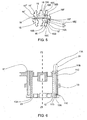
- a plurality of extraction elements or extraction bars 21, 22 of the extractor assembly 20 are visible.
- the extractor assembly is provided with a first circular array of extraction bars 21, having a relatively greater length, and a second circular array of extraction bars 22, having a relatively shorter length.
- each extraction bar 21, 22 can be inserted into the channels 15, 16 of the inner and outer arrays of the twisting device 10, respectively through a second face 23 or extraction face 23 ( figure 6 ) of such a device.
- each extraction bar 21, 22 extends according to a prevalent longitudinal extension direction and includes an element body or bar body comprising an extraction portion 2.1A, 22A and a longitudinal rib 21B, 22B projecting from the extraction portion and extending parallel to the prevalent longitudinal extension direction of the extraction bar.
- the extraction portion 21A, 22A is suitable for passing through one of the channels 15, 16
- the rib 21B, 22B is suitable for passing through the groove 15A, 16A associated with such a channel.
- the extraction portion 21A, 22A is substantially counter-shaped with respect to the channel 15, 16 whereas the rib 21B, 22B is substantially counter-shaped with respect to the extension groove 15A, 16A.
- the extraction bars 21, 22 would have a respective section, perpendicular to their longitudinal extension direction, which is substantially T-shaped.
- the legs of the T would correspond to ribs 21B, 22B and the cross ends of the T, joined to the legs, would correspond to the extraction portions 21A, 22A.
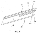
- a pair of extraction bars 21, 22 is illustrated, in greater detail with respect to figure 7 , according to a currently preferred embodiment.
- an extraction bar 21 of the first array and an extraction bar 22 of the second array are joined to one another through a preferably plate-shaped joint portion 24. More in particular, in the example of figure 8 such extraction bars project from an end of the joint portion 24 so that the pair of extraction bars 21, 22 and the joint portion overall have a fork shape.
- each extraction bar of the first array is joined to an adjacent extraction bar of the second array in the way described above.
- a twisting device including at least one circular array of channels each of which is associated with a circumferentially projecting groove, makes it possible to carry out the extraction of the bar conductors from the twisting device by using extraction bars equipped with a structure stiffened with a reinforcement rib intended to be received in a respective groove during the extraction step. Therefore, this advantageously makes it possible to substantially reduce or avoid, with the same section of the channels perpendicular to the twisting axis and, thus, with the same cross section of the bar conductors, the possibility of the extraction bars bending during the extraction step.
- a twisting device in order to provide for stator or rotor windings having any number of phases, can comprise further bodies coaxial with the aforementioned first and second body, in particular provided with respective channels and relative channel extension grooves.
- an extractor assembly according to the present description can comprise any number of circular arrays of extraction elements.
Landscapes
- Engineering & Computer Science (AREA)
- Manufacturing & Machinery (AREA)
- Power Engineering (AREA)
- Business, Economics & Management (AREA)
- Primary Health Care (AREA)
- Physics & Mathematics (AREA)
- Human Resources & Organizations (AREA)
- Marketing (AREA)
- Economics (AREA)
- Strategic Management (AREA)
- Tourism & Hospitality (AREA)
- General Health & Medical Sciences (AREA)
- General Business, Economics & Management (AREA)
- General Physics & Mathematics (AREA)
- Theoretical Computer Science (AREA)
- Health & Medical Sciences (AREA)
- Manufacture Of Motors, Generators (AREA)
- Windings For Motors And Generators (AREA)
Claims (15)
- Verdrillungsvorrichtung (10), die angepasst ist, um gleichzeitig eine Mehrzahl elektrischer Stableiter (11) zu verdrillen, zum Herstellen einer Stator- oder Rotorwicklung für eine Elektromaschine, die folgende Merkmale aufweist:- zumindest einen ersten Körper (12), der sich um eine Verdrillungsachse (Z-Z) herum erstreckt und ein erstes kreisförmiges Array von Kanälen (15) mit einer Mitte an einer derartigen Achse (Z-Z) aufweist; und- zumindest einen zweiten Körper (13), der sich um den ersten Körper (12) herum und koaxial zu demselben erstreckt, der ein zweites kreisförmiges Array von Kanälen (16) mit einer Mitte an der Verdrillungsachse (Z-Z) aufweist;wobei ein Kanal (15) des ersten Arrays und ein Kanal (16) des zweiten Arrays angepasst sind, um Seite an Seite platziert zu sein und radial (RR) zueinander in Bezug auf die Verdrillungsachse (Z-Z) ausgerichtet zu sein, um einen ersten bzw. einen zweiten Arm (11B, 11C) eines der Stableiter (11) aufzunehmen, wobei der erste und/oder zweite Körper (12, 13) angepasst ist/sind, um um die Achse (Z-Z) in Drehung versetzt zu werden, um diese Arme um eine vorbestimmte Menge auseinander (11 B, 11 C) zu bewegen;
wobei die Verdrillungsvorrichtung (10) dadurch gekennzeichnet ist, dass sie, jedem der Kanäle (15) zumindest eines des ersten und zweiten Arrays zugeordnet, eine Kanalerweiterungsrille (15A) aufweist, die sich in einer Richtung parallel zu der Verdrillungsachse (Z-Z) längs erstreckt und von dem jeweiligen Kanal (15) in einer Umfangsrichtung (CC) in Bezug auf die Achse (Z-Z) vorsteht. - Verdrillungsvorrichtung (10) gemäß Anspruch 1, die Kanalwände (15B, 15C, 15D, 15E, 15F) aufweist, die geeignet sind zum Definieren des Kanals (15), von dem die Kanalerweiterungsrille (15A) vorsteht, sowie zumindest eine Rillenwand (15', 15", 15"'), die mit den Kanalwänden (15B, 15C, 15D, 15E, 15F) verbunden ist, die geeignet ist zum Definieren der Rille (15A).
- Verdrillungsvorrichtung (10) gemäß Anspruch 2, bei der die Kanalwände (15B, 15C, 15D, 15E, 15F) zumindest ein Paar gegenüberliegender Haltewände (15B, 15D, 15E) umfassen, die geeignet sind zum Ineingriffnehmen, an zwei gegenüberliegenden Seiten, eines Arms (11B) eines der Stableiter (11), die in dem Kanal (15) untergebracht sind.
- Verdrillungsvorrichtung (10) gemäß Anspruch 3, bei der die gegenüberliegenden Haltewände (15B, 15D, 15E) sich in der Radialrichtung (RR) erstrecken.
- Verdrillungsvorrichtung (10) gemäß Anspruch 3, bei der die gegenüberliegenden Haltewände (15B, 15D, 15E) eine Schubwand (15B) gegenüber von der Rille (15A) aufweisen, wobei die Schubwand (15B) geeignet ist zum Ineingriffnehmen einer Fläche des Arms (11B), der in dem Kanal (15) untergebracht ist, um eine Schubwirkung auf diesen Arm (11B) in der Rotationsrichtung eines derartigen Kanals auszuüben, wenn der Körper (12), an dem ein derartiger Kanal gebildet ist, in Drehung versetzt wird, um die Stableiter (11) zu verdrillen.
- Verdrillungsvorrichtung (10) gemäß Anspruch 2, die eine Mehrzahl von Rillenwänden (15', 15", 15"') aufweist, die geeignet sind zum Definieren der Rille (15A).
- Verdrillungsvorrichtung (10) gemäß Anspruch 6, bei der die Rillenwände (15', 15", 15"') ein Paar gegenüberliegender Rillenwände (15', 15") aufweisen, die sich in der Umfangsrichtung (CC) erstrecken.
- Verdrillungsvorrichtung (10) gemäß Anspruch 2, bei der die Rille (15A) und der jeweilige Kanal (15) eine Radialerstreckung aufweisen, die definiert ist durch die Rillenwand (15', 15", 15''') bzw. durch die Kanalwände (15B, 15C, 15D, 15E, 15F), wobei die Radialerstreckung der Rille (15A) relativ kleiner ist als die Radialerstreckung des jeweiligen Kanals (15).
- Verdrillungsvorrichtung (10) gemäß Anspruch 8, bei der die Rille (15A) radial in Bezug auf den Kanal (15), von dem dieselbe vorsteht, versetzt (RR) ist.
- Verdrillungsvorrichtung (10) gemäß Anspruch 9, bei der der erste und der zweite Körper (12, 13) durch eine Trennlücke (18) getrennt sind, und bei der die Rille (15A) radial in Richtung der Lücke (18) versetzt (RR) ist.
- Verdrillungsvorrichtung (10) gemäß Anspruch 1, bei der die Rille (15A) geeignet ist zum Leerbleiben, wenn ein Arm (11B) eines der Stableiter (11) in dem Kanal (15), von dem diese Rille vorsteht (15A), untergebracht ist.
- Verdrillungsvorrichtung (10) gemäß Anspruch 1, bei der die Rille (15A, 16A) an jedem Kanal (15, 16) des ersten und zweiten Arrays gebildet ist, und bei der die Rillen (15A, 16A), die von einem Kanal (15) des ersten Arrays bzw. von einem Kanal (16) des zweiten Arrays vorstehen, die Seite an Seite angeordnet und radial (RR) ausgerichtet sind, in entgegengesetzten Richtungen umfangsmäßig (CC) vorstehen.
- Auszieheranordnung (20), die geeignet ist zum Zusammenwirken mit einer Verdrillungsvorrichtung gemäß Anspruch 1, die zumindest ein kreisförmiges Array von Ausziehelementen (21) aufweist, um die Stableiter (11) aus der Verdrillungsvorrichtung (10) herauszuziehen, wobei jedes Herausziehelement (21) sich gemäß einer vorherrschenden Längserstreckungsrichtung erstreckt und einen Elementkörper mit einem Ausziehabschnitt (21 A) und einem Längssteg (21 B) aufweist, der von dem Ausziehabschnitt (21 A) vorsteht und sich parallel zu der Längserstreckungsrichtung des Ausziehelements (21) erstreckt, wobei der Ausziehabschnitt (21 A) und der Längssteg (21 B) geeignet sind zum Durchlaufen eines Kanals (15) der Arrays bzw. der Kanalerweiterungsrille (15A), die einem derartigen Kanal (15) zugeordnet ist.
- Auszieheranordnung (20) gemäß Anspruch 13, die ein erstes kreisförmiges Array von Ausziehelementen (21), die geeignet sind zum Durchlaufen der Kanäle (15) des ersten Arrays, ein zweites kreisförmiges Array von Ausziehelementen (21), die geeignet sind zum Durchlaufen der Kanäle (16) des zweiten Arrays, und zumindest einen Verbindungsabschnitt (24) aufweist, der geeignet ist zum Verbinden eines Ausziehelements (21) des ersten Arrays und eines Ausziehelements (22) des zweiten Arrays miteinander.
- Gerät (1) zum Erzeugen eines Stator- oder Rotorpacks einer Elektromaschine mit einer Verdrillungsvorrichtung (10) gemäß einem der Ansprüche 1 bis 12 und einer Auszieheranordnung (20) gemäß Anspruch 13 oder 14.
Applications Claiming Priority (1)
| Application Number | Priority Date | Filing Date | Title |
|---|---|---|---|
| PCT/IT2010/000174 WO2011132207A1 (en) | 2010-04-23 | 2010-04-23 | Twisting device adapted to simultaneously twist a plurality of electric bar conductors for making a stator or rotor winding for an electric machine and an extractor assembly suitable for cooperating with said twisting device |
Publications (2)
| Publication Number | Publication Date |
|---|---|
| EP2561602A1 EP2561602A1 (de) | 2013-02-27 |
| EP2561602B1 true EP2561602B1 (de) | 2014-03-19 |
Family
ID=44065522
Family Applications (1)
| Application Number | Title | Priority Date | Filing Date |
|---|---|---|---|
| EP10726316.2A Active EP2561602B1 (de) | 2010-04-23 | 2010-04-23 | Drillvorrichtung zum simultanen drehen mehrerer elektrischer stableiter zur herstellung einer stator- oder rotorwicklung für eine elektromaschine und extraktoranordnung zur kooperation mit dieser drillvorrichtung |
Country Status (11)
| Country | Link |
|---|---|
| US (1) | US8561447B2 (de) |
| EP (1) | EP2561602B1 (de) |
| JP (1) | JP5249479B2 (de) |
| KR (1) | KR101652564B1 (de) |
| CN (1) | CN102844970B (de) |
| BR (1) | BR112012027017B1 (de) |
| CA (1) | CA2793690C (de) |
| EA (1) | EA021408B1 (de) |
| ES (1) | ES2472916T3 (de) |
| MX (1) | MX2012011177A (de) |
| WO (1) | WO2011132207A1 (de) |
Families Citing this family (17)
| Publication number | Priority date | Publication date | Assignee | Title |
|---|---|---|---|---|
| WO2012004817A1 (en) | 2010-07-08 | 2012-01-12 | Tecnomatic S.P.A. | Method and apparatus for twisting bar conductors, in particular for bar windings of electric machines |
| CN103098355B (zh) | 2010-07-28 | 2015-09-30 | 泰克马奇有限公司 | 用于扭转电机的条式绕组的预成型导体条的装置和方法 |
| BR112013017243B1 (pt) | 2011-01-04 | 2020-09-29 | Tecnomatic S.P.A | Método e dispositivo de torção para torcer porções de extremidade livres de condutores em barra e aparelho de torção |
| CN103894513B (zh) * | 2014-03-27 | 2015-06-24 | 浙江永磁电机有限公司 | 一种起动马达转子线圈液压数控扭头机 |
| JP5888387B1 (ja) * | 2014-10-22 | 2016-03-22 | ミツミ電機株式会社 | 電池保護回路及び電池保護装置、並びに電池パック |
| DE102014226224A1 (de) * | 2014-12-17 | 2016-06-23 | Robert Bosch Gmbh | Verfahren zum Formen zumindest eines U-förmigen Wickelelements für einen elektromagnetisch erregbaren Kern einer elektrischen Rotationsmaschine |
| DE102014226229A1 (de) * | 2014-12-17 | 2016-06-23 | Robert Bosch Gmbh | Verfahren zum Entnehmen von U-förmigen Wickelelementen für einen elektromagnetisch erregbaren Kern einer elektrischen Rotationsmaschine aus einem Schränkwerkzeug |
| DE102016221355A1 (de) * | 2016-10-28 | 2018-05-03 | Thyssenkrupp Ag | Positioniervorrichtung zum Positionieren von Kupferstäben und Verfahren |
| CN109309438B (zh) * | 2017-07-28 | 2020-11-13 | 天津市松正电动汽车技术股份有限公司 | 一种扁线电机绕组扭转设备 |
| DE102018103927A1 (de) * | 2018-02-21 | 2019-08-22 | Grob-Werke Gmbh & Co. Kg | Biegevorrichtung zum Verbiegen von aus einem ringförmigen Gehäuse vorstehenden Drahtenden und Demontageverfahren hierfür |
| DE102018114580A1 (de) * | 2018-06-18 | 2019-12-19 | copperING S.r.l. | Verfahren und Vorrichtung zum Formen eines Wicklungselements |
| CN108599487B (zh) * | 2018-06-27 | 2024-09-27 | 成都华川电装有限责任公司 | 一种定子铜线弯形的机械设备 |
| IT201800010213A1 (it) * | 2018-11-09 | 2020-05-09 | Grob Italy S R L | Dispositivo, apparecchiatura e procedimento per l’attorcigliatura di fili conduttori da applicare in una macchina elettrica. |
| DE102019130534B4 (de) * | 2019-11-12 | 2023-08-10 | Gehring Technologies Gmbh + Co. Kg | Vorrichtung zum Umformen eines in einem Statorkern angeordneten Leiterstücks sowie ein entsprechendes Verfahren |
| CN114260389A (zh) * | 2021-12-23 | 2022-04-01 | 成都华川电装有限责任公司 | 定子端线头的扭曲成型装置及方法 |
| CN114749565B (zh) * | 2022-04-25 | 2023-05-23 | 安徽乾天精密科技有限公司 | 基于模具更换使用的自动换模组件 |
| CN120638798B (zh) * | 2025-05-19 | 2026-06-12 | 儒拉玛特华锐自动化技术(常州)有限公司 | 用于定子绕组的扭转成型工装及扭转成型设备 |
Family Cites Families (10)
| Publication number | Priority date | Publication date | Assignee | Title |
|---|---|---|---|---|
| JP3196738B2 (ja) * | 1998-09-11 | 2001-08-06 | 株式会社デンソー | ステータ製造装置及びステータ製造方法 |
| JP3928400B2 (ja) * | 2001-10-15 | 2007-06-13 | トヨタ自動車株式会社 | 回転電機のコイル製造装置 |
| JP3775349B2 (ja) * | 2002-06-03 | 2006-05-17 | 株式会社デンソー | 回転電機の固定子巻線の製造方法、巻線構造および巻線の製造方法 |
| US7343662B2 (en) * | 2003-09-18 | 2008-03-18 | Denso Corporation | Manufacturing method of stator coil composed of conductor segments |
| JP3960313B2 (ja) * | 2004-01-30 | 2007-08-15 | 株式会社デンソー | コイル成形装置およびコイル成形方法 |
| JP2008148521A (ja) * | 2006-12-13 | 2008-06-26 | Denso Corp | チャック装置 |
| US7941910B2 (en) | 2007-03-22 | 2011-05-17 | Tecnomatic S.P.A. | Method for removing winding conductors from a twisting machine and placing them in a rotor stator stack |
| US7721413B2 (en) * | 2007-03-22 | 2010-05-25 | Tecnomatic, S.P.A. | Method for inserting of preformed hairpin conductors into a rotor or stator |
| US7805825B2 (en) * | 2007-03-22 | 2010-10-05 | Tecnomatic S.P.A. | Method for forming motor winding conductors |
| JP5097569B2 (ja) * | 2008-02-14 | 2012-12-12 | 株式会社日立製作所 | コイルの製造方法および製造装置 |
-
2010
- 2010-04-23 EP EP10726316.2A patent/EP2561602B1/de active Active
- 2010-04-23 BR BR112012027017-6A patent/BR112012027017B1/pt active IP Right Grant
- 2010-04-23 CN CN201080066289.7A patent/CN102844970B/zh active Active
- 2010-04-23 US US13/387,726 patent/US8561447B2/en active Active
- 2010-04-23 ES ES10726316.2T patent/ES2472916T3/es active Active
- 2010-04-23 EA EA201201459A patent/EA021408B1/ru not_active IP Right Cessation
- 2010-04-23 KR KR1020127026218A patent/KR101652564B1/ko active Active
- 2010-04-23 JP JP2013505601A patent/JP5249479B2/ja active Active
- 2010-04-23 MX MX2012011177A patent/MX2012011177A/es active IP Right Grant
- 2010-04-23 CA CA2793690A patent/CA2793690C/en active Active
- 2010-04-23 WO PCT/IT2010/000174 patent/WO2011132207A1/en not_active Ceased
Also Published As
| Publication number | Publication date |
|---|---|
| EA021408B1 (ru) | 2015-06-30 |
| EA201201459A1 (ru) | 2013-03-29 |
| US8561447B2 (en) | 2013-10-22 |
| MX2012011177A (es) | 2012-11-23 |
| CN102844970B (zh) | 2015-07-01 |
| ES2472916T3 (es) | 2014-07-03 |
| KR101652564B1 (ko) | 2016-08-30 |
| US20130025737A1 (en) | 2013-01-31 |
| KR20130079998A (ko) | 2013-07-11 |
| BR112012027017A2 (pt) | 2016-07-19 |
| CA2793690C (en) | 2017-06-27 |
| CN102844970A (zh) | 2012-12-26 |
| WO2011132207A1 (en) | 2011-10-27 |
| JP5249479B2 (ja) | 2013-07-31 |
| EP2561602A1 (de) | 2013-02-27 |
| CA2793690A1 (en) | 2011-10-27 |
| JP2013526248A (ja) | 2013-06-20 |
| BR112012027017B1 (pt) | 2020-02-27 |
Similar Documents
| Publication | Publication Date | Title |
|---|---|---|
| CA2793690C (en) | Twisting device adapted to simultaneously twist a plurality of electric bar conductors for making a stator or rotor winding for an electric machine and an extractor assembly suitable for cooperating with said twisting device | |
| EP3118978B1 (de) | Statorherstellungsvorrichtung und herstellungsverfahren | |
| US9608491B2 (en) | Stator, motor, blower, and stator manufacturing method | |
| EP2661801B1 (de) | Verfahren und vorrichtung zur biegung von endabschnitten von stableiteren, insbesondere für stabwicklungen von elektrischen maschinen | |
| US3760493A (en) | Method of winding a dynamoelectric machine with reduced coil distortion | |
| EP3285369B1 (de) | Stator und elektromotorische maschine | |
| CN102624124B (zh) | 具有相位间绝缘器的定子组件和组装定子组件的方法 | |
| EP3203611B1 (de) | Motor und stator dafür | |
| KR102272772B1 (ko) | 회전 전기 기계용 와이어 조립체 및 그 와이어 조립체를 얻기 위한 대응 방법 | |
| CN105393437A (zh) | 旋转电机的定子绕组、旋转电机的定子、旋转电机的定子的制造方法、以及用于旋转电机的定子的制造的夹具 | |
| CN105896782B (zh) | 径向间隙型电动机及其绕线配置方法 | |
| EP3422536B1 (de) | Drahtverbindungsstruktur und drahtverbindungsverfahren eines dreiphasigen motors und dreiphasiger motor | |
| KR101146440B1 (ko) | 작업성이 개선된 모터의 버스바 하우징 및 이를 이용한 코일의 결선 방법 | |
| EP0331651A1 (de) | Verfahren und Einrichtung zum Einschieben einer Vielzahl von Phasenisolatoren in die Ständernuten einer dynamoelektrischen Maschine | |
| US20050212379A1 (en) | Module winding system for electrical machines and methods of electrical connection | |
| KR20230058138A (ko) | 스큐형 스테이터의 제조 방법 | |
| EP4510427A1 (de) | Motorstatorwicklungsstruktur | |
| EP4468568A1 (de) | Elektrische drehmaschine | |
| ITRM20100192A1 (it) | Dispositivo di torcitura adatto a torcere simultaneamente una plura lità di conduttori elettrici a barra per formare un avvolgimento statorico o rotorico di una macchina elettrica e gruppo estrattore adatto a cooperare con detto dispositivo di torcit | |
| KR20180013692A (ko) | 스테이터 및 이를 갖춘 모터 | |
| JPWO2024185370A5 (de) | ||
| CN115133728A (zh) | 定子的制造方法 |
Legal Events
| Date | Code | Title | Description |
|---|---|---|---|
| PUAI | Public reference made under article 153(3) epc to a published international application that has entered the european phase |
Free format text: ORIGINAL CODE: 0009012 |
|
| 17P | Request for examination filed |
Effective date: 20120911 |
|
| AK | Designated contracting states |
Kind code of ref document: A1 Designated state(s): AT BE BG CH CY CZ DE DK EE ES FI FR GB GR HR HU IE IS IT LI LT LU LV MC MK MT NL NO PL PT RO SE SI SK SM TR |
|
| DAX | Request for extension of the european patent (deleted) | ||
| RIC1 | Information provided on ipc code assigned before grant |
Ipc: H02K 15/04 20060101AFI20130905BHEP |
|
| GRAP | Despatch of communication of intention to grant a patent |
Free format text: ORIGINAL CODE: EPIDOSNIGR1 |
|
| INTG | Intention to grant announced |
Effective date: 20131024 |
|
| GRAS | Grant fee paid |
Free format text: ORIGINAL CODE: EPIDOSNIGR3 |
|
| GRAA | (expected) grant |
Free format text: ORIGINAL CODE: 0009210 |
|
| AK | Designated contracting states |
Kind code of ref document: B1 Designated state(s): AT BE BG CH CY CZ DE DK EE ES FI FR GB GR HR HU IE IS IT LI LT LU LV MC MK MT NL NO PL PT RO SE SI SK SM TR |
|
| REG | Reference to a national code |
Ref country code: GB Ref legal event code: FG4D |
|
| REG | Reference to a national code |
Ref country code: CH Ref legal event code: EP |
|
| REG | Reference to a national code |
Ref country code: AT Ref legal event code: REF Ref document number: 658236 Country of ref document: AT Kind code of ref document: T Effective date: 20140415 |
|
| REG | Reference to a national code |
Ref country code: IE Ref legal event code: FG4D |
|
| REG | Reference to a national code |
Ref country code: DE Ref legal event code: R096 Ref document number: 602010014432 Country of ref document: DE Effective date: 20140430 |
|
| REG | Reference to a national code |
Ref country code: ES Ref legal event code: FG2A Ref document number: 2472916 Country of ref document: ES Kind code of ref document: T3 Effective date: 20140703 |
|
| PG25 | Lapsed in a contracting state [announced via postgrant information from national office to epo] |
Ref country code: LT Free format text: LAPSE BECAUSE OF FAILURE TO SUBMIT A TRANSLATION OF THE DESCRIPTION OR TO PAY THE FEE WITHIN THE PRESCRIBED TIME-LIMIT Effective date: 20140319 Ref country code: NO Free format text: LAPSE BECAUSE OF FAILURE TO SUBMIT A TRANSLATION OF THE DESCRIPTION OR TO PAY THE FEE WITHIN THE PRESCRIBED TIME-LIMIT Effective date: 20140619 |
|
| REG | Reference to a national code |
Ref country code: NL Ref legal event code: VDEP Effective date: 20140319 |
|
| REG | Reference to a national code |
Ref country code: AT Ref legal event code: MK05 Ref document number: 658236 Country of ref document: AT Kind code of ref document: T Effective date: 20140319 |
|
| REG | Reference to a national code |
Ref country code: LT Ref legal event code: MG4D |
|
| PG25 | Lapsed in a contracting state [announced via postgrant information from national office to epo] |
Ref country code: SE Free format text: LAPSE BECAUSE OF FAILURE TO SUBMIT A TRANSLATION OF THE DESCRIPTION OR TO PAY THE FEE WITHIN THE PRESCRIBED TIME-LIMIT Effective date: 20140319 Ref country code: CY Free format text: LAPSE BECAUSE OF FAILURE TO SUBMIT A TRANSLATION OF THE DESCRIPTION OR TO PAY THE FEE WITHIN THE PRESCRIBED TIME-LIMIT Effective date: 20140319 Ref country code: FI Free format text: LAPSE BECAUSE OF FAILURE TO SUBMIT A TRANSLATION OF THE DESCRIPTION OR TO PAY THE FEE WITHIN THE PRESCRIBED TIME-LIMIT Effective date: 20140319 |
|
| PG25 | Lapsed in a contracting state [announced via postgrant information from national office to epo] |
Ref country code: LV Free format text: LAPSE BECAUSE OF FAILURE TO SUBMIT A TRANSLATION OF THE DESCRIPTION OR TO PAY THE FEE WITHIN THE PRESCRIBED TIME-LIMIT Effective date: 20140319 Ref country code: HR Free format text: LAPSE BECAUSE OF FAILURE TO SUBMIT A TRANSLATION OF THE DESCRIPTION OR TO PAY THE FEE WITHIN THE PRESCRIBED TIME-LIMIT Effective date: 20140319 |
|
| PG25 | Lapsed in a contracting state [announced via postgrant information from national office to epo] |
Ref country code: EE Free format text: LAPSE BECAUSE OF FAILURE TO SUBMIT A TRANSLATION OF THE DESCRIPTION OR TO PAY THE FEE WITHIN THE PRESCRIBED TIME-LIMIT Effective date: 20140319 Ref country code: CZ Free format text: LAPSE BECAUSE OF FAILURE TO SUBMIT A TRANSLATION OF THE DESCRIPTION OR TO PAY THE FEE WITHIN THE PRESCRIBED TIME-LIMIT Effective date: 20140319 Ref country code: BE Free format text: LAPSE BECAUSE OF FAILURE TO SUBMIT A TRANSLATION OF THE DESCRIPTION OR TO PAY THE FEE WITHIN THE PRESCRIBED TIME-LIMIT Effective date: 20140319 Ref country code: IS Free format text: LAPSE BECAUSE OF FAILURE TO SUBMIT A TRANSLATION OF THE DESCRIPTION OR TO PAY THE FEE WITHIN THE PRESCRIBED TIME-LIMIT Effective date: 20140719 Ref country code: NL Free format text: LAPSE BECAUSE OF FAILURE TO SUBMIT A TRANSLATION OF THE DESCRIPTION OR TO PAY THE FEE WITHIN THE PRESCRIBED TIME-LIMIT Effective date: 20140319 Ref country code: RO Free format text: LAPSE BECAUSE OF FAILURE TO SUBMIT A TRANSLATION OF THE DESCRIPTION OR TO PAY THE FEE WITHIN THE PRESCRIBED TIME-LIMIT Effective date: 20140319 Ref country code: BG Free format text: LAPSE BECAUSE OF FAILURE TO SUBMIT A TRANSLATION OF THE DESCRIPTION OR TO PAY THE FEE WITHIN THE PRESCRIBED TIME-LIMIT Effective date: 20140619 |
|
| PG25 | Lapsed in a contracting state [announced via postgrant information from national office to epo] |
Ref country code: PL Free format text: LAPSE BECAUSE OF FAILURE TO SUBMIT A TRANSLATION OF THE DESCRIPTION OR TO PAY THE FEE WITHIN THE PRESCRIBED TIME-LIMIT Effective date: 20140319 Ref country code: SK Free format text: LAPSE BECAUSE OF FAILURE TO SUBMIT A TRANSLATION OF THE DESCRIPTION OR TO PAY THE FEE WITHIN THE PRESCRIBED TIME-LIMIT Effective date: 20140319 Ref country code: MC Free format text: LAPSE BECAUSE OF FAILURE TO SUBMIT A TRANSLATION OF THE DESCRIPTION OR TO PAY THE FEE WITHIN THE PRESCRIBED TIME-LIMIT Effective date: 20140319 Ref country code: AT Free format text: LAPSE BECAUSE OF FAILURE TO SUBMIT A TRANSLATION OF THE DESCRIPTION OR TO PAY THE FEE WITHIN THE PRESCRIBED TIME-LIMIT Effective date: 20140319 |
|
| REG | Reference to a national code |
Ref country code: CH Ref legal event code: PL |
|
| REG | Reference to a national code |
Ref country code: DE Ref legal event code: R097 Ref document number: 602010014432 Country of ref document: DE |
|
| PG25 | Lapsed in a contracting state [announced via postgrant information from national office to epo] |
Ref country code: PT Free format text: LAPSE BECAUSE OF FAILURE TO SUBMIT A TRANSLATION OF THE DESCRIPTION OR TO PAY THE FEE WITHIN THE PRESCRIBED TIME-LIMIT Effective date: 20140721 |
|
| PLBE | No opposition filed within time limit |
Free format text: ORIGINAL CODE: 0009261 |
|
| STAA | Information on the status of an ep patent application or granted ep patent |
Free format text: STATUS: NO OPPOSITION FILED WITHIN TIME LIMIT |
|
| REG | Reference to a national code |
Ref country code: IE Ref legal event code: MM4A |
|
| PG25 | Lapsed in a contracting state [announced via postgrant information from national office to epo] |
Ref country code: DK Free format text: LAPSE BECAUSE OF FAILURE TO SUBMIT A TRANSLATION OF THE DESCRIPTION OR TO PAY THE FEE WITHIN THE PRESCRIBED TIME-LIMIT Effective date: 20140319 Ref country code: LI Free format text: LAPSE BECAUSE OF NON-PAYMENT OF DUE FEES Effective date: 20140430 Ref country code: CH Free format text: LAPSE BECAUSE OF NON-PAYMENT OF DUE FEES Effective date: 20140430 |
|
| 26N | No opposition filed |
Effective date: 20141222 |
|
| PG25 | Lapsed in a contracting state [announced via postgrant information from national office to epo] |
Ref country code: IT Free format text: LAPSE BECAUSE OF FAILURE TO SUBMIT A TRANSLATION OF THE DESCRIPTION OR TO PAY THE FEE WITHIN THE PRESCRIBED TIME-LIMIT Effective date: 20140319 |
|
| REG | Reference to a national code |
Ref country code: DE Ref legal event code: R097 Ref document number: 602010014432 Country of ref document: DE Effective date: 20141222 |
|
| PG25 | Lapsed in a contracting state [announced via postgrant information from national office to epo] |
Ref country code: IE Free format text: LAPSE BECAUSE OF NON-PAYMENT OF DUE FEES Effective date: 20140423 |
|
| PG25 | Lapsed in a contracting state [announced via postgrant information from national office to epo] |
Ref country code: SI Free format text: LAPSE BECAUSE OF FAILURE TO SUBMIT A TRANSLATION OF THE DESCRIPTION OR TO PAY THE FEE WITHIN THE PRESCRIBED TIME-LIMIT Effective date: 20140319 |
|
| PG25 | Lapsed in a contracting state [announced via postgrant information from national office to epo] |
Ref country code: MT Free format text: LAPSE BECAUSE OF FAILURE TO SUBMIT A TRANSLATION OF THE DESCRIPTION OR TO PAY THE FEE WITHIN THE PRESCRIBED TIME-LIMIT Effective date: 20140319 |
|
| REG | Reference to a national code |
Ref country code: FR Ref legal event code: PLFP Year of fee payment: 7 |
|
| PG25 | Lapsed in a contracting state [announced via postgrant information from national office to epo] |
Ref country code: SM Free format text: LAPSE BECAUSE OF FAILURE TO SUBMIT A TRANSLATION OF THE DESCRIPTION OR TO PAY THE FEE WITHIN THE PRESCRIBED TIME-LIMIT Effective date: 20140319 |
|
| PG25 | Lapsed in a contracting state [announced via postgrant information from national office to epo] |
Ref country code: GR Free format text: LAPSE BECAUSE OF FAILURE TO SUBMIT A TRANSLATION OF THE DESCRIPTION OR TO PAY THE FEE WITHIN THE PRESCRIBED TIME-LIMIT Effective date: 20140620 |
|
| PG25 | Lapsed in a contracting state [announced via postgrant information from national office to epo] |
Ref country code: TR Free format text: LAPSE BECAUSE OF FAILURE TO SUBMIT A TRANSLATION OF THE DESCRIPTION OR TO PAY THE FEE WITHIN THE PRESCRIBED TIME-LIMIT Effective date: 20140319 Ref country code: HU Free format text: LAPSE BECAUSE OF FAILURE TO SUBMIT A TRANSLATION OF THE DESCRIPTION OR TO PAY THE FEE WITHIN THE PRESCRIBED TIME-LIMIT; INVALID AB INITIO Effective date: 20100423 Ref country code: LU Free format text: LAPSE BECAUSE OF NON-PAYMENT OF DUE FEES Effective date: 20140423 |
|
| REG | Reference to a national code |
Ref country code: FR Ref legal event code: PLFP Year of fee payment: 8 |
|
| REG | Reference to a national code |
Ref country code: FR Ref legal event code: PLFP Year of fee payment: 9 |
|
| PG25 | Lapsed in a contracting state [announced via postgrant information from national office to epo] |
Ref country code: MK Free format text: LAPSE BECAUSE OF FAILURE TO SUBMIT A TRANSLATION OF THE DESCRIPTION OR TO PAY THE FEE WITHIN THE PRESCRIBED TIME-LIMIT Effective date: 20140319 |
|
| P01 | Opt-out of the competence of the unified patent court (upc) registered |
Effective date: 20230529 |
|
| PGFP | Annual fee paid to national office [announced via postgrant information from national office to epo] |
Ref country code: ES Payment date: 20260504 Year of fee payment: 17 |
|
| PGFP | Annual fee paid to national office [announced via postgrant information from national office to epo] |
Ref country code: GB Payment date: 20260423 Year of fee payment: 17 |
|
| PGFP | Annual fee paid to national office [announced via postgrant information from national office to epo] |
Ref country code: DE Payment date: 20260423 Year of fee payment: 17 |
|
| PGFP | Annual fee paid to national office [announced via postgrant information from national office to epo] |
Ref country code: FR Payment date: 20260430 Year of fee payment: 17 |