EP2561311B2 - Operation d'une machine de mesure de coordonnées ou d'une machine outil - Google Patents
Operation d'une machine de mesure de coordonnées ou d'une machine outil Download PDFInfo
- Publication number
- EP2561311B2 EP2561311B2 EP11717500.0A EP11717500A EP2561311B2 EP 2561311 B2 EP2561311 B2 EP 2561311B2 EP 11717500 A EP11717500 A EP 11717500A EP 2561311 B2 EP2561311 B2 EP 2561311B2
- Authority
- EP
- European Patent Office
- Prior art keywords
- machine part
- machine
- maximum
- movement
- jerk
- Prior art date
- Legal status (The legal status is an assumption and is not a legal conclusion. Google has not performed a legal analysis and makes no representation as to the accuracy of the status listed.)
- Active
Links
Images
Classifications
-
- G—PHYSICS
- G01—MEASURING; TESTING
- G01B—MEASURING LENGTH, THICKNESS OR SIMILAR LINEAR DIMENSIONS; MEASURING ANGLES; MEASURING AREAS; MEASURING IRREGULARITIES OF SURFACES OR CONTOURS
- G01B5/00—Measuring arrangements characterised by the use of mechanical techniques
- G01B5/004—Measuring arrangements characterised by the use of mechanical techniques for measuring coordinates of points
- G01B5/008—Measuring arrangements characterised by the use of mechanical techniques for measuring coordinates of points using coordinate measuring machines
-
- G—PHYSICS
- G01—MEASURING; TESTING
- G01B—MEASURING LENGTH, THICKNESS OR SIMILAR LINEAR DIMENSIONS; MEASURING ANGLES; MEASURING AREAS; MEASURING IRREGULARITIES OF SURFACES OR CONTOURS
- G01B21/00—Measuring arrangements or details thereof, where the measuring technique is not covered by the other groups of this subclass, unspecified or not relevant
- G01B21/02—Measuring arrangements or details thereof, where the measuring technique is not covered by the other groups of this subclass, unspecified or not relevant for measuring length, width, or thickness
- G01B21/04—Measuring arrangements or details thereof, where the measuring technique is not covered by the other groups of this subclass, unspecified or not relevant for measuring length, width, or thickness by measuring coordinates of points
- G01B21/047—Accessories, e.g. for positioning, for tool-setting, for measuring probes
Definitions
- the invention relates to a method for operating a coordinate measuring machine or a machine tool.
- the invention also relates to such a machine.
- Such machines have movable machine parts, in many cases a tool being arranged on an arm of the machine (e.g. a quill or a horizontally oriented arm).
- the tool can be a machining tool for machining a workpiece (in the case of a machine tool) or a scanning tool for scanning the surface of a tool (in the case of a coordinate measuring machine).
- coordinate measuring machine the term coordinate measuring machine is often used.
- the measuring tool is e.g. around a stylus, at the free end of which a stylus (e.g. a stylus ball) is arranged, with which the surface of the workpiece is scanned. In this case, the position of the probe at which it touches the surface of the workpiece is determined from the machine's measuring system.
- the movable machine parts When the tool is moved towards the surface of the workpiece, the movable machine parts can start to vibrate, particularly in the area of the tool and the measuring systems which may also be arranged there.
- the drive motors are one possible cause of the vibrations. Another possible cause is the movement itself.
- the vibrations affect the measuring accuracy of the position measurement. It is therefore important to avoid such oscillations as much as possible or at least to keep the oscillation amplitude very low.
- the oscillation amplitude can be determined by measuring the acceleration as a function of time.
- DE 102 29 821 A1 describes a method for operating a coordinate measuring machine with a probe head that can be accelerated in the measuring volume of the coordinate measuring machine and with a control device that limits the acceleration of the probe head to permissible maximum values depending on the mass of the probe head.
- the coordinate measuring machine has an accelerated moving probe head, which has a probe, and a control unit which limits the acceleration of the probe head to permissible maximum values, permissible maximum values for the acceleration of the probe head being specified as a function of the mass of the probe.
- the coordinate measuring machine has a probe head that can be moved in the coordinate directions and a probe pin that is replaceably fastened to the probe head.
- Length information of the stylus is calculated from calibration data and this length information is compared with a predetermined threshold value. If the threshold value is exceeded, the acceleration of the stylus is reduced. The acceleration is advantageously reduced proportionally to the exceeding of the threshold value.
- the length information of the stylus is regarded as the distance from the center point of the relevant stylus ball to the coupling point of the stylus on the probe head.
- US 2009/0055118 A1 describes a method for planning a trajectory of a machine part, in particular a probe head that is mounted on a coordinate measuring machine. It is determined whether for a given trajectory the angular velocity or acceleration around an axis of rotation exceeds a predetermined limit value. If this is the case, parameters are adjusted so that the angular velocity or acceleration does not exceed the limit value.
- DE 103 21 970 A1 describes a motion control of a movable machine element of a numerically controlled machine tool or production machine on a specified path of movement of a machine element, with support points being defined in the workspace of the machine, with the maximum possible path jolt and / or the maximum possible path acceleration and / or the maximum possible for each support point Path speed of the machine element is determined or specified and the movement of the machine element on the path of movement is carried out with the maximum possible path jerk and / or the maximum possible path acceleration and / or the maximum possible path speed of the machine element.
- the invention is based on the following fundamental considerations:
- the vibration behavior of the machine part (for example the machining tool, the touch tool and / or the measuring systems) is not only dependent on the dynamics of the movement of the machine part, but also dependent on the position and / or orientation of the machine part. This dependency is more pronounced, the larger the spatial area in which the machine part can be moved.
- the arm being able to be extended to different extents from the perspective of supporting the arm, the more the arm is extended the more the free end of the arm tends to vibrate .
- the arm is e.g. around an arm of a so-called horizontal arm device that is aligned with its longitudinal axis in the horizontal direction or approximately in the horizontal direction, or around other arms, e.g. the quill of a coordinate measuring machine in portal design.
- the condition of the arm's suspension can also influence the susceptibility to vibration.
- the susceptibility of the quill to vibrations also depends on the position of the crossbeam that carries the quill, at which the quill is located.
- a value for at least one dynamic parameter (according to the claims, the maximum permissible acceleration or the maximum permissible jerk, ie the third time derivative of the location or the first of the acceleration) of the machine or the machine part, which depends on the orientation and / or varies depending on the position of the machine part.
- a corresponding characteristic curve of the dynamic parameter will be specified, the characteristic curve defining the values of the parameter as a function of the position and / or the orientation. If the specified values of the parameter are not only dependent on one variable (either the position in a linear direction or the alignment of the machine part), it is better to speak of a characteristic map instead of a characteristic curve.
- the invention makes it possible to specify higher values of the respective dynamic parameter in non-vibration critical areas or in areas of the position and / or alignment of the machine part that are less susceptible to vibration. Therefore, it is possible to work with higher speeds of the machine part in these areas and the higher speed can be maintained for longer or later reduced to lower speeds.
- the jerk is limited to specified maximum values, it is possible to maintain the speed until shortly before the tool touches the workpiece, to carry out high negative accelerations and yet not to exceed the maximum values of the jerk. Since the jerk is the most important influencing variable for the excitation of vibrations in such movement processes, strong vibrations are nevertheless avoided.
- the maximum value of the parameter or parameters can depend not only on the position and / or orientation of the machine part, but on at least one other state variable, such as the ambient temperature, the type and / or weight of the tool and / or the measuring systems.
- a method for operating a coordinate measuring machine or a machine tool wherein a movement of a machine part is controlled in such a way that a predetermined maximum acceleration and / or a predetermined maximum jerk is not exceeded during the movement of the machine part, the maximum acceleration and / or the maximum jerk varies depending on the position of the machine part and / or depending on the alignment of the machine part.
- An example of a variable alignment of the machine part is a stylus of a coordinate measuring machine which is attached to a joint so that the alignment of the longitudinal axis of the stylus can be changed.
- Another example is a machine arm which carries the tool and / or the measuring systems at its free end and whose longitudinal axis can be aligned differently.
- the machine part can be positioned at different distances from a support of the machine part, the maximum acceleration and / or the maximum jerk being specified so that it varies depending on the distance, e.g. B. decreases with increasing distance.
- the distance of the machine part from the support is the position on which the maximum value of the dynamic parameter (e.g. acceleration and / or jerk) depends.
- the maximum value of the dynamic variable can be specified in such a way that it decreases with increasing susceptibility to vibrations and vice versa.
- the machine part and / or the machine is more susceptible to vibration the greater the distance.
- the susceptibility to vibration decreases with increasing distance, at least in parts of the distance. After a minimum of the susceptibility to vibrations has been reached, the susceptibility to vibrations can increase again.
- One example is a coordinate measuring machine with a portal design, in which the quill carries the measuring systems and the probe at its lower end.
- the quill is in its highest position, that is, not extended downwards, a considerable part of the quill protrudes upwards beyond the cross member.
- the quill is therefore susceptible to vibrations at the smallest distance between the measuring systems and the probe from the suspension or support on the cross member. If the quill is now extended downwards, the susceptibility to vibration initially decreases until the quill is based on its support on Cross member protrudes about the same distance up and down. With further extension downwards, the susceptibility to vibration increases again.
- the method is particularly advantageous if the movement is a movement in which the machine part approaches a workpiece in order to contact the workpiece, the movement having a movement phase in which the speed of the machine part decreases.
- a movement phase in which the speed of the machine part decreases.
- a coordinate measuring machine or machine tool which has a movable machine part and a controller, the controller being designed to control a movement of the machine part in such a way that a predetermined maximum acceleration and / or a predetermined maximum jerk does not occur when the machine part is moved is exceeded, the maximum acceleration and / or the maximum jerk varying depending on the position of the machine part and / or depending on the alignment of the machine part.
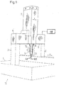
- the coordinate measuring machine 11 shown is of the portal type.
- the portal is formed by two upwardly projecting supports 2, 3 and by a cross member 4 which rests on the supports 2, 3 at its opposite ends.
- the supports 2, 3 can be moved in the z-direction on a measuring table 1 of the device.
- the device 11 has a quill 7 which can be moved in the x direction along the longitudinal axis of the cross member 4.
- a holder 8 of the quill 7 carries a sensor 5 at the lower end of the quill 7, which sensor is connected to the carrier 8 via a releasable coupling 10.
- the sensor 5 contains the measuring systems of the device with which a deflection of a stylus 41 can be measured when it touches a workpiece with its stylus ball 45 arranged at the lower free end.
- the carrier 8 with the parts 5, 41 attached to it can be moved in the y-direction, the z-direction, the x-direction and the y-direction being perpendicular to one another in pairs so that they define the coordinate axes of a Cartesian coordinate system.
- a scale 6 is arranged on the cross member 4 running in the x-direction, so that, depending on the position of the quill 7, a respective assigned measured value can be automatically read on the scale 6.
- the controller 14 of the device 11, which controls the movements of the various machine parts of the device 11 in the z-direction, y-direction and x-direction, is in the top right Fig. 1 represented by a rectangle.
- the controller 14 is designed to observe the specifications when moving the stylus 41, which are specified by specifying position-dependent maximum values of the dynamic variables of the device.
- the controller 14 or the controller of another coordinate measuring device or a machine tool can read in the corresponding specifications for the maximum values of the parameters from a computer-readable file.
- a characteristic curve and / or a characteristic diagram is stored in this file for each parameter that is dependent on the operating state (in particular the position and / or orientation of the tool).
- the parameter values contained in the characteristic curve and / or the characteristic diagram are dependent on the respective state variable, in particular the position and / or alignment of the tool and / or the measuring systems.
- the characteristic curve or map does not directly contain the maximum value of the dynamic variable (e.g. acceleration or jerk), but only the factor for adapting a specified, fixed parameter value.
- a piece-wise linear characteristic curve can be defined.
- the state-dependent adjustment factor is determined for the relevant parameter as a function of the state variable (e.g. the position with respect to the axis) so that the parameter value can change continuously (i.e. continuously) depending on the state.
- a suitable algorithm is used to determine an overall adjustment factor from the individual adjustment factors resulting from the respective characteristic curves to be multiplied by the specified, fixed value of the parameter.
- the respective parameter values can be determined experimentally for different states of the machine, so that a specific, desired behavior of the machine results. These parameter values determined in this way can be used, for example, as the support points mentioned above for the characteristic curves. In this way the control of the machine is set.
- the user can use experiments to determine a limit value or several limit values for the dynamic parameters (in particular the maximum value of the acceleration and the maximum value of the jerk) for individual positions of a probe in such a way that the desired measurement accuracy is achieved at these positions with the shortest possible measurement time .
- the pairs thus determined from the position of the probe head and the associated parameter value can then define a table of values that corresponds to a corresponding parameter characteristic.
- the parameter characteristic or the parameter characteristics can e.g. can be set and / or changed by means of a graphical user interface of a computer and with the help of an input device (such as a computer mouse). This saves time, mistakes are avoided and the user can make the input while he is already seeing a representation of the characteristic curve.
- entering parameter values can also be done manually, e.g. using a keyboard, possible.
- the controller calculates the respective parameter value or the respective parameter values depending on the current operating status (the status is defined in particular by the position and / or alignment of the tool and / or the measuring systems) (e.g. using the corresponding control software).
- the controller can perform one of the methods described above (e.g. linear interpolation).
- the sequence of movements is planned in advance and the respectively valid parameter values are determined in advance for the planned movement sequence.
- the movement planning can initially be carried out without considering the parameter values (e.g. maximum value of the acceleration and / or the jerk) and the planned movement can then be checked, but before the movement is carried out, to determine whether the conditions specified by the parameters are met . If the conditions are not met, the motion planning can be adjusted so that the conditions are met. However, it is also possible to take the parameter values into account when planning the first movement.
- a small maximum value for the amount of acceleration can result in the braking distance of a movement of the machine part being longer than expected. This could result in a hard hitting of the machine part e.g. on the workpiece to be machined or measured.
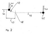
- Fig. 2 shows a stylus 41 with a stylus ball 45 at the lower free end of the stylus 41, which is, for example, the stylus according to FIG Fig. 1 or Figures 3 and 4 can act.
- the stylus 41 is moved with its stylus ball 45 along the travel path 49. Up to the position 48 along the travel path 49, the probe ball 45 is moved at a constant, high speed. From position 48, a phase of the movement begins in which the probe ball 45 is braked. A local area is marked by a double arrow 47 in which no contact of the probe ball 45 with a workpiece is expected. In the direction of arrow 44, however, from the point of view of position 48, a workpiece can be located behind area 47. The movement of the probe ball 45 is therefore braked in the area 47.
- the point marked with an asterisk 43 on the travel path 49 marks the place at which the deceleration (negative acceleration) is changed most quickly with regard to its amount, ie at which the jerk reaches the maximum value with regard to its amount. In many cases the jerk is decisive for whether and with what amplitude mechanical vibrations are excited.
- the braking phase can also be controlled differently and thus carried out differently. Since a workpiece can be located beyond the area 47 from the point of view of the position 48, braking can be carried out with the greatest possible jolt as soon as the area 47 is reached.
- the point 43 on the travel path 49 could, for example, mark the point at which a very small maximum value for the jerk is specified, which is significantly smaller than the maximum value of the jerk that applies to the point 48 on the travel path 49.
- the maximum value of the jerk is preferably reduced continuously as it enters the area 47. Should vibrations still be excited when entering area 47 are, they can at least partially subside during the movement in the area 47.
- the distance of the stylus 41 from a support of the machine arm which carries the stylus increases in many cases as the workpiece is approached. For this reason too, the specified maximum value for the jerk should decrease in the course of the travel path 49.
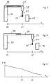
- Fig. 3 shows a coordinate measuring machine of the horizontal arm design.
- a fixed base 17 of the device carries a horizontal arm which has a carrier element 19 and an element 21 which is telescopic with respect to the carrier element 19.
- Fig. 4 shows a compared to Fig. 3 Extended position of the element 21.
- the measuring system 23 is fastened to the element 21, to which the stylus 41 with its stylus ball 45 is in turn attached.
- the stylus 41 can be deflected with respect to the measuring system 23, so that it is deflected when the workpiece 15 comes into contact.
- x Down in Fig. 3 and in Fig. 4 the axis of travel is shown, the position variable of which is designated by x.
- a reference point of the traversing axis (left in FIGS. 3 and 4 ) is denoted by x0.
- the position of the probe ball 45 in the in Fig. 3 The state shown is denoted by x1.
- the extended position of the probe ball 45 in the Fig. 4 is denoted by x2.
- Fig. 5 shows a parameter curve.
- the state variable is in turn the position of the tool, for example the stylus ball 45 FIGS. 3 and 4 , along an axis of movement of the tool.
- the parameter P can, for example, be the maximum value of the acceleration or the jerk that is permitted when the tool is moved. Is the characteristic according to Fig. 5 on the in FIGS. 3 and 4 In relation to the situations shown, the progressive extension of the telescopic element 21 and thus the stylus 41 with its stylus ball 45 results in a decrease in the parameter value. For example, in the case that the parameter P is the maximum value of the jerk, the parameter value decreases with the extension of the telescopic element 21.
- the invention prevents imprecise measurement results from a coordinate measuring machine from being achieved or undesired or imprecise workpiece machining by a machine tool in operating states with increased susceptibility to vibration.
- the movement of the respective machine part is carried out with high dynamics, i.e. high accelerations and / or high jolts are permitted.
- the dynamics are reduced, i.e. lower accelerations and / or jolts are permitted. In this way, the movements of the machine parts susceptible to vibration can be carried out in the shortest possible time.
Landscapes
- Physics & Mathematics (AREA)
- General Physics & Mathematics (AREA)
- Length Measuring Devices With Unspecified Measuring Means (AREA)
- Numerical Control (AREA)
- A Measuring Device Byusing Mechanical Method (AREA)
- Automatic Control Of Machine Tools (AREA)
Claims (6)
- Procédé pour faire fonctionner une machine de mesure de coordonnées (11) ou une machine-outil, un mouvement d'une partie de machine (41) étant commandé de manière à ce que, lors du mouvement de la partie de machine (41), une accélération maximale prédéterminée et/ou une saccade maximale prédéterminée (P) ne soi(en)t pas dépassée(s), l'accélération maximale et/ou la saccade maximale variant en fonction de la position de la partie de machine (41) et/ou en fonction de l'orientation de la partie de machine à l'intérieur de la zone spatiale dans laquelle il est possible de faire bouger la partie de machine (41), à savoir de manière correspondant à une ligne caractéristique prédéterminée ou à un champ caractéristique prédéterminé de l'accélération maximale et/ou de la saccade maximale, et la ligne caractéristique ou le champ caractéristique définissant les valeurs de l'accélération maximale et/ou de la saccade maximale en tant que fonction de la position et/ou de l'orientation de la partie de machine (41), où, pour l'accélération maximale et/ou la saccade maximale (P) dans des zones partielles de la zone spatiale ayant une susceptibilité plus importante aux oscillations de la partie de machine (41), des valeurs plus petites que dans des zones partielles de la zone spatiale ayant une moindre susceptibilité aux oscillations de la partie de machine (41) sont prédéfinies.
- Procédé selon la revendication précédente, la partie de machine (41), vue à partir d'un support (17) de la partie de machine (41), pouvant être positionnée à une distance (x) différente, et l'accélération maximale et/ou la saccade maximale étant prédéterminée(s) de manière à ce qu'elle(s) varie(nt) en fonction de la distance.
- Procédé selon l'une des revendications précédentes, le mouvement étant un mouvement lors duquel la partie de machine (41) est rapprochée d'une pièce d'œuvre (15) afin d'entrer en contact avec la pièce d'œuvre (15), le mouvement présentant une phase de mouvement lors de laquelle la vitesse de la partie de machine (41) diminue.
- Machine de mesure de coordonnées (11) ou machine-outil, avec une partie de machine (41) mobile et avec une commande (14), laquelle est conçue pour commander un mouvement de la partie de machine (41) de manière à ce que, lors du mouvement de la partie de machine (41), une accélération maximale prédéterminée et/ou une saccade maximale prédéterminée ne soi(en)t pas dépassée(s), l'accélération maximale et/ou la saccade maximale variant en fonction de la position de la partie de machine (41) et/ou en fonction de l'orientation de la partie de machine à l'intérieur de la zone spatiale dans laquelle il est possible de faire bouger la partie de machine (41), à savoir de manière correspondant à une ligne caractéristique prédéterminée ou à un champ caractéristique prédéterminé de l'accélération maximale et/ou de la saccade maximale, et la ligne caractéristique ou le champ caractéristique définissant les valeurs de l'accélération maximale et/ou de la saccade maximale en tant que fonction de la position et/ou de l'orientation de la partie de machine (41), où, pour l'accélération maximale et/ou la saccade maximale (P) dans des zones partielles de la zone spatiale ayant une susceptibilité plus importante aux oscillations de la partie de machine (41), des valeurs plus petites que dans des zones partielles de la zone spatiale ayant une moindre susceptibilité aux oscillations de la partie de machine (41) sont prédéfinies.
- Machine selon la revendication précédente, la partie de machine (41), vue à partir d'un support (17) de la partie de machine (41), pouvant être positionnée à une distance (x) différente et l'accélération maximale et/ou la saccade maximale étant prédéterminée(s) de manière à ce qu'elle(s) varie(nt) en fonction de la distance.
- Machine selon l'une des deux revendications précédentes, le mouvement étant un mouvement lors duquel la partie de machine (41) est rapprochée d'une pièce d'œuvre (15) afin d'entrer en contact avec la pièce d'œuvre (15), et la commande (14) étant conçue de manière à ce que le mouvement présente une phase de mouvement lors de laquelle la vitesse de la partie de machine (41) diminue.
Applications Claiming Priority (2)
| Application Number | Priority Date | Filing Date | Title |
|---|---|---|---|
| DE201010015780 DE102010015780A1 (de) | 2010-04-20 | 2010-04-20 | Betrieb einer Koordinatenmessmaschine oder einer Werkzeugmaschine |
| PCT/EP2011/002103 WO2011131375A1 (fr) | 2010-04-20 | 2011-04-18 | Fonctionnement d'une machine de mesure de coordonnées ou d'une machine outil |
Publications (3)
| Publication Number | Publication Date |
|---|---|
| EP2561311A1 EP2561311A1 (fr) | 2013-02-27 |
| EP2561311B1 EP2561311B1 (fr) | 2014-10-29 |
| EP2561311B2 true EP2561311B2 (fr) | 2020-12-30 |
Family
ID=44314203
Family Applications (1)
| Application Number | Title | Priority Date | Filing Date |
|---|---|---|---|
| EP11717500.0A Active EP2561311B2 (fr) | 2010-04-20 | 2011-04-18 | Operation d'une machine de mesure de coordonnées ou d'une machine outil |
Country Status (5)
| Country | Link |
|---|---|
| US (1) | US9207059B2 (fr) |
| EP (1) | EP2561311B2 (fr) |
| CN (1) | CN102859315B (fr) |
| DE (1) | DE102010015780A1 (fr) |
| WO (1) | WO2011131375A1 (fr) |
Families Citing this family (7)
| Publication number | Priority date | Publication date | Assignee | Title |
|---|---|---|---|---|
| US9851197B2 (en) * | 2012-12-13 | 2017-12-26 | Carl Zeiss Industrielle Messtechnik Gmbh | Device with displaceable device part, in particular coordinate measuring device or machine tool |
| DE102014220540B4 (de) * | 2013-10-11 | 2016-03-17 | Carl Zeiss Industrielle Messtechnik Gmbh | Koordinatenmessgerät mit Bedieneinrichtung für eine Bedienperson und Verfahren zum Betreiben des Koordinatenmessgeräts |
| EP3176657A1 (fr) * | 2015-12-02 | 2017-06-07 | Siemens Aktiengesellschaft | Determination de la rigidite d'une chaine cinematique d'une machine, en particulier d'une machine de production ou d'une machine-outil |
| US10765782B2 (en) | 2016-05-03 | 2020-09-08 | Medtronic, Inc. | Hemostatic devices and methods of use |
| US10933174B2 (en) | 2016-05-03 | 2021-03-02 | Medtronic, Inc. | Hemostatic devices and methods of use |
| CN107131849A (zh) * | 2017-06-20 | 2017-09-05 | 中国船舶重工集团公司第七0七研究所 | 基于单光栅尺可伸缩机械臂的纸海图点经纬度读取方法 |
| EP3696632A1 (fr) * | 2019-02-15 | 2020-08-19 | Siemens Aktiengesellschaft | Procédé de fonctionnement d'une machine de fabrication à commande numérique ainsi que commande numérique correspondante |
Citations (2)
| Publication number | Priority date | Publication date | Assignee | Title |
|---|---|---|---|---|
| WO1995027930A1 (fr) † | 1994-04-08 | 1995-10-19 | Siemens Aktiengesellschaft | Systeme permettant de compenser la non-linearite d'arbres de machines |
| DE10321970A1 (de) † | 2003-05-15 | 2004-12-09 | Siemens Ag | Verfahren zur Bewegungsführung eines bewegbaren Maschinenelementes einer numerisch gesteuerten Werkzeug-oder Produktionsmaschine |
Family Cites Families (22)
| Publication number | Priority date | Publication date | Assignee | Title |
|---|---|---|---|---|
| GB2045437B (en) * | 1979-03-30 | 1984-02-08 | Renishaw Electrical Ltd | Coordinate measuring machine |
| US4882848A (en) * | 1987-07-30 | 1989-11-28 | Carl-Zeiss-Stiftung, Heidenheim/Brenz | Probe head for a coordinate-measuring instrument |
| US5222034A (en) * | 1990-10-10 | 1993-06-22 | Shelton Russell S | Measuring method and apparatus |
| DE19614883C2 (de) | 1996-04-16 | 2003-08-21 | Leitz Brown & Sharpe Mestechni | Verfahren zur Antastung und zum Scannen bei Koordinatenmeßgeräten |
| US6058618A (en) * | 1997-09-09 | 2000-05-09 | Giddings & Lewis, Inc. | Coordinate measuring machine |
| GB9815830D0 (en) | 1998-07-22 | 1998-09-16 | Renishaw Plc | Method of and apparatus for reducing vibrations on probes carried by coordinate measuring machines |
| DE19960191B4 (de) | 1999-12-14 | 2010-05-20 | Carl Zeiss Industrielle Messtechnik Gmbh | Verfahren zur Sicherung eines Koordinatenmessgerätes vor Bedienfehlern |
| DE10024976C2 (de) | 2000-01-17 | 2002-10-17 | Middex Electronic Gmbh | Überwachungseinrichtung |
| DE10024975C2 (de) | 2000-01-17 | 2002-07-11 | Middex Electronic Gmbh | Überwachungseinrichtung |
| EP1478898B1 (fr) * | 2002-02-28 | 2006-07-05 | Carl Zeiss Industrielle Messtechnik GmbH | Sonde pour appareil de mesure a coordonnees |
| DE10229821B4 (de) * | 2002-06-28 | 2004-11-11 | Carl Zeiss | Koordinatenmeßgerät und Verfahren zur Steuerung eines Koordinatenmeßgerätes mit variabler Tastkopfmasse |
| US20040018336A1 (en) * | 2002-07-29 | 2004-01-29 | Brian Farnworth | Thermally insulating products for footwear and other apparel |
| DE10257856A1 (de) | 2002-12-11 | 2004-07-08 | Leitz Messtechnik Gmbh | Verfahren zur Schwingungsdämpfung eines Koordinatenmessgerätes sowie Koordinatenmessgerät |
| JP4782990B2 (ja) | 2004-05-31 | 2011-09-28 | 株式会社ミツトヨ | 表面倣い測定装置、表面倣い測定方法、表面倣い測定プログラムおよび記録媒体 |
| DE102004038416B4 (de) * | 2004-07-30 | 2014-02-06 | Carl Zeiss Industrielle Messtechnik Gmbh | Verfahren zum Bestimmen von Raumkoordinaten eines Messpunktes an einem Messobjekt sowie entsprechendes Koordinatenmessgerät |
| GB0508217D0 (en) * | 2005-04-25 | 2005-06-01 | Renishaw Plc | Method for scanning the surface of a workpiece |
| DE102006003362A1 (de) | 2006-01-19 | 2007-07-26 | Carl Zeiss Industrielle Messtechnik Gmbh | Koordinatenmessgerät und Verfahren zum Betreiben eines Koordinatenmessgeräts |
| DE102006009181A1 (de) | 2006-02-24 | 2007-09-06 | Carl Zeiss Industrielle Messtechnik Gmbh | Sichere Überwachung der Geschwindigkeit bei Koordinatenmessgeräten |
| DE102006055005A1 (de) * | 2006-11-17 | 2008-05-29 | Carl Zeiss Industrielle Messtechnik Gmbh | Verfahren und Vorrichtung zum Bestimmen von Raumkoordinaten an einer Vielzahl von Messpunkten |
| DE102007004423A1 (de) | 2007-01-23 | 2008-07-31 | Carl Zeiss Industrielle Messtechnik Gmbh | Steuerung eines Betriebes eines Koordinatenmessgerätes |
| JP5274782B2 (ja) | 2007-03-27 | 2013-08-28 | 株式会社ミツトヨ | 表面性状測定装置、表面性状測定方法及び表面性状測定プログラム |
| DE102008011534B9 (de) * | 2008-02-28 | 2011-02-24 | Carl Zeiss Industrielle Messtechnik Gmbh | Manuell steuerbares Koordinatenmessgerät und Verfahren zum Betreiben eines solchen Koordinatenmessgeräts |
-
2010
- 2010-04-20 DE DE201010015780 patent/DE102010015780A1/de not_active Ceased
-
2011
- 2011-04-18 US US13/642,597 patent/US9207059B2/en active Active
- 2011-04-18 WO PCT/EP2011/002103 patent/WO2011131375A1/fr active Application Filing
- 2011-04-18 EP EP11717500.0A patent/EP2561311B2/fr active Active
- 2011-04-18 CN CN201180019809.3A patent/CN102859315B/zh active Active
Patent Citations (2)
| Publication number | Priority date | Publication date | Assignee | Title |
|---|---|---|---|---|
| WO1995027930A1 (fr) † | 1994-04-08 | 1995-10-19 | Siemens Aktiengesellschaft | Systeme permettant de compenser la non-linearite d'arbres de machines |
| DE10321970A1 (de) † | 2003-05-15 | 2004-12-09 | Siemens Ag | Verfahren zur Bewegungsführung eines bewegbaren Maschinenelementes einer numerisch gesteuerten Werkzeug-oder Produktionsmaschine |
Non-Patent Citations (2)
| Title |
|---|
| Definition des Begriffs 'Kennlinie' aus der Online-Enzyklopädie 'Wikipedia', Stand 16. Januar 2010 † |
| KLEF, HANS B.: "NC/CNC Handbuch 2000", 1999, CARL HANSER VERLAG , Munchen, pages: 68 - 69 † |
Also Published As
| Publication number | Publication date |
|---|---|
| WO2011131375A8 (fr) | 2012-01-26 |
| WO2011131375A1 (fr) | 2011-10-27 |
| CN102859315A (zh) | 2013-01-02 |
| EP2561311B1 (fr) | 2014-10-29 |
| EP2561311A1 (fr) | 2013-02-27 |
| CN102859315B (zh) | 2016-04-20 |
| US20130041497A1 (en) | 2013-02-14 |
| US9207059B2 (en) | 2015-12-08 |
| DE102010015780A1 (de) | 2011-10-20 |
Similar Documents
| Publication | Publication Date | Title |
|---|---|---|
| EP2561311B2 (fr) | Operation d'une machine de mesure de coordonnées ou d'une machine outil | |
| EP2089667B1 (fr) | Procédé et dispositif de détermination des coordonnées spatiales de plusieurs points de mesure | |
| EP2010864B1 (fr) | Scannerisation d'une surface avec un appareil de mesure de coordonnees | |
| EP2331907B1 (fr) | Procédé de mesure d'une pièce et appareil de mesure de coordonnées | |
| EP2972078B1 (fr) | Méthode de correction de déviation angulaire lors de l'opération d'un appareil de mesure de coordonnées | |
| DE112016002797T5 (de) | Kalibriervorrichtung und robotersystem, das eine solche verwendet | |
| EP3240994B1 (fr) | Détection d'écarts géométriques d'une commande de trajectoire dans un appareil de mesure de coordonnées ou dans une machine-outil | |
| EP2016368B1 (fr) | Procédé et dispositif de mesure d'un point sur la surface d'une pièce | |
| DE4436507A1 (de) | Verfahren zur Koordinatenmessung an Werkstücken | |
| DE102016012065A1 (de) | Robotersystem mit Funktion zum Berechnen von Position und Ausrichtung eines Sensors | |
| DE102016220097A1 (de) | Bestimmung einer Position eines beweglichen Teils eines Koordinatenmessgerätes | |
| DE102007057093A1 (de) | Verfahren zum Kalibrieren eines Koordinatenmessgerätes | |
| DE102017008570A1 (de) | Werkzeugmaschine und Verfahren zum Glätten eines Werkstücks | |
| EP0684448A2 (fr) | Procédé pour la mesure de coordonnées d'objets | |
| DE102014014524A1 (de) | Werkzeugbahnanzeigevorrichtung, mit einer Anzeigeeinheit für Bahndaten | |
| WO2016030268A1 (fr) | Procédé de palpage point par point d'une pièce et appareil de mesure de coordonnées | |
| EP3480557A1 (fr) | Procédé de mesure d'une pièce à usiner à l'aide d'un appareil de mesure de coordonnées | |
| WO2011098487A1 (fr) | Procédé pour le réglage d'un processus de mesure au moyen de surfaces virtuelles | |
| EP2679962B1 (fr) | Dispositif de mesure de position | |
| EP3551375A1 (fr) | Machine-outil pour l'usinage d'une pièce par enlèvement de copeaux | |
| DE102021212817B4 (de) | Wiederholte Positionsbestimmung eines beweglichen Teils eines Koordinatenmessgerätes | |
| EP2124116B1 (fr) | Procédé de commande d'un appareil de mesure des coordonnées à commande numérique assistée par ordinateur et appareil de mesure de coordonnées | |
| DE102021102619A1 (de) | Steuereinheit und steuerungsverfahren | |
| DE102020122685A1 (de) | Parametereinstellverfahren und steuervorrichtung | |
| DE102019220060A1 (de) | Verfahren zum Kalibrieren eines taktilen Sensors |
Legal Events
| Date | Code | Title | Description |
|---|---|---|---|
| PUAI | Public reference made under article 153(3) epc to a published international application that has entered the european phase |
Free format text: ORIGINAL CODE: 0009012 |
|
| 17P | Request for examination filed |
Effective date: 20120831 |
|
| AK | Designated contracting states |
Kind code of ref document: A1 Designated state(s): AL AT BE BG CH CY CZ DE DK EE ES FI FR GB GR HR HU IE IS IT LI LT LU LV MC MK MT NL NO PL PT RO RS SE SI SK SM TR |
|
| DAX | Request for extension of the european patent (deleted) | ||
| GRAP | Despatch of communication of intention to grant a patent |
Free format text: ORIGINAL CODE: EPIDOSNIGR1 |
|
| INTG | Intention to grant announced |
Effective date: 20140522 |
|
| GRAS | Grant fee paid |
Free format text: ORIGINAL CODE: EPIDOSNIGR3 |
|
| GRAA | (expected) grant |
Free format text: ORIGINAL CODE: 0009210 |
|
| AK | Designated contracting states |
Kind code of ref document: B1 Designated state(s): AL AT BE BG CH CY CZ DE DK EE ES FI FR GB GR HR HU IE IS IT LI LT LU LV MC MK MT NL NO PL PT RO RS SE SI SK SM TR |
|
| REG | Reference to a national code |
Ref country code: GB Ref legal event code: FG4D Free format text: NOT ENGLISH |
|
| REG | Reference to a national code |
Ref country code: CH Ref legal event code: EP |
|
| REG | Reference to a national code |
Ref country code: AT Ref legal event code: REF Ref document number: 693807 Country of ref document: AT Kind code of ref document: T Effective date: 20141115 |
|
| REG | Reference to a national code |
Ref country code: IE Ref legal event code: FG4D Free format text: LANGUAGE OF EP DOCUMENT: GERMAN |
|
| REG | Reference to a national code |
Ref country code: DE Ref legal event code: R096 Ref document number: 502011004826 Country of ref document: DE Effective date: 20141204 |
|
| REG | Reference to a national code |
Ref country code: NL Ref legal event code: VDEP Effective date: 20141029 |
|
| REG | Reference to a national code |
Ref country code: LT Ref legal event code: MG4D |
|
| PG25 | Lapsed in a contracting state [announced via postgrant information from national office to epo] |
Ref country code: IS Free format text: LAPSE BECAUSE OF FAILURE TO SUBMIT A TRANSLATION OF THE DESCRIPTION OR TO PAY THE FEE WITHIN THE PRESCRIBED TIME-LIMIT Effective date: 20150228 Ref country code: ES Free format text: LAPSE BECAUSE OF FAILURE TO SUBMIT A TRANSLATION OF THE DESCRIPTION OR TO PAY THE FEE WITHIN THE PRESCRIBED TIME-LIMIT Effective date: 20141029 Ref country code: LT Free format text: LAPSE BECAUSE OF FAILURE TO SUBMIT A TRANSLATION OF THE DESCRIPTION OR TO PAY THE FEE WITHIN THE PRESCRIBED TIME-LIMIT Effective date: 20141029 Ref country code: NO Free format text: LAPSE BECAUSE OF FAILURE TO SUBMIT A TRANSLATION OF THE DESCRIPTION OR TO PAY THE FEE WITHIN THE PRESCRIBED TIME-LIMIT Effective date: 20150129 Ref country code: NL Free format text: LAPSE BECAUSE OF FAILURE TO SUBMIT A TRANSLATION OF THE DESCRIPTION OR TO PAY THE FEE WITHIN THE PRESCRIBED TIME-LIMIT Effective date: 20141029 Ref country code: FI Free format text: LAPSE BECAUSE OF FAILURE TO SUBMIT A TRANSLATION OF THE DESCRIPTION OR TO PAY THE FEE WITHIN THE PRESCRIBED TIME-LIMIT Effective date: 20141029 Ref country code: PT Free format text: LAPSE BECAUSE OF FAILURE TO SUBMIT A TRANSLATION OF THE DESCRIPTION OR TO PAY THE FEE WITHIN THE PRESCRIBED TIME-LIMIT Effective date: 20150302 |
|
| PG25 | Lapsed in a contracting state [announced via postgrant information from national office to epo] |
Ref country code: RS Free format text: LAPSE BECAUSE OF FAILURE TO SUBMIT A TRANSLATION OF THE DESCRIPTION OR TO PAY THE FEE WITHIN THE PRESCRIBED TIME-LIMIT Effective date: 20141029 Ref country code: GR Free format text: LAPSE BECAUSE OF FAILURE TO SUBMIT A TRANSLATION OF THE DESCRIPTION OR TO PAY THE FEE WITHIN THE PRESCRIBED TIME-LIMIT Effective date: 20150130 Ref country code: HR Free format text: LAPSE BECAUSE OF FAILURE TO SUBMIT A TRANSLATION OF THE DESCRIPTION OR TO PAY THE FEE WITHIN THE PRESCRIBED TIME-LIMIT Effective date: 20141029 Ref country code: SE Free format text: LAPSE BECAUSE OF FAILURE TO SUBMIT A TRANSLATION OF THE DESCRIPTION OR TO PAY THE FEE WITHIN THE PRESCRIBED TIME-LIMIT Effective date: 20141029 Ref country code: CY Free format text: LAPSE BECAUSE OF FAILURE TO SUBMIT A TRANSLATION OF THE DESCRIPTION OR TO PAY THE FEE WITHIN THE PRESCRIBED TIME-LIMIT Effective date: 20141029 Ref country code: PL Free format text: LAPSE BECAUSE OF FAILURE TO SUBMIT A TRANSLATION OF THE DESCRIPTION OR TO PAY THE FEE WITHIN THE PRESCRIBED TIME-LIMIT Effective date: 20141029 Ref country code: LV Free format text: LAPSE BECAUSE OF FAILURE TO SUBMIT A TRANSLATION OF THE DESCRIPTION OR TO PAY THE FEE WITHIN THE PRESCRIBED TIME-LIMIT Effective date: 20141029 |
|
| REG | Reference to a national code |
Ref country code: DE Ref legal event code: R026 Ref document number: 502011004826 Country of ref document: DE |
|
| PG25 | Lapsed in a contracting state [announced via postgrant information from national office to epo] |
Ref country code: RO Free format text: LAPSE BECAUSE OF FAILURE TO SUBMIT A TRANSLATION OF THE DESCRIPTION OR TO PAY THE FEE WITHIN THE PRESCRIBED TIME-LIMIT Effective date: 20141029 Ref country code: DK Free format text: LAPSE BECAUSE OF FAILURE TO SUBMIT A TRANSLATION OF THE DESCRIPTION OR TO PAY THE FEE WITHIN THE PRESCRIBED TIME-LIMIT Effective date: 20141029 Ref country code: SK Free format text: LAPSE BECAUSE OF FAILURE TO SUBMIT A TRANSLATION OF THE DESCRIPTION OR TO PAY THE FEE WITHIN THE PRESCRIBED TIME-LIMIT Effective date: 20141029 Ref country code: EE Free format text: LAPSE BECAUSE OF FAILURE TO SUBMIT A TRANSLATION OF THE DESCRIPTION OR TO PAY THE FEE WITHIN THE PRESCRIBED TIME-LIMIT Effective date: 20141029 Ref country code: CZ Free format text: LAPSE BECAUSE OF FAILURE TO SUBMIT A TRANSLATION OF THE DESCRIPTION OR TO PAY THE FEE WITHIN THE PRESCRIBED TIME-LIMIT Effective date: 20141029 |
|
| PLBI | Opposition filed |
Free format text: ORIGINAL CODE: 0009260 |
|
| 26 | Opposition filed |
Opponent name: SIEMENS AKTIENGESELLSCHAFT Effective date: 20150729 |
|
| PLAX | Notice of opposition and request to file observation + time limit sent |
Free format text: ORIGINAL CODE: EPIDOSNOBS2 |
|
| PG25 | Lapsed in a contracting state [announced via postgrant information from national office to epo] |
Ref country code: MC Free format text: LAPSE BECAUSE OF FAILURE TO SUBMIT A TRANSLATION OF THE DESCRIPTION OR TO PAY THE FEE WITHIN THE PRESCRIBED TIME-LIMIT Effective date: 20141029 Ref country code: LU Free format text: LAPSE BECAUSE OF FAILURE TO SUBMIT A TRANSLATION OF THE DESCRIPTION OR TO PAY THE FEE WITHIN THE PRESCRIBED TIME-LIMIT Effective date: 20150418 |
|
| REG | Reference to a national code |
Ref country code: CH Ref legal event code: PL |
|
| PLAF | Information modified related to communication of a notice of opposition and request to file observations + time limit |
Free format text: ORIGINAL CODE: EPIDOSCOBS2 |
|
| REG | Reference to a national code |
Ref country code: IE Ref legal event code: MM4A |
|
| PG25 | Lapsed in a contracting state [announced via postgrant information from national office to epo] |
Ref country code: LI Free format text: LAPSE BECAUSE OF NON-PAYMENT OF DUE FEES Effective date: 20150430 Ref country code: CH Free format text: LAPSE BECAUSE OF NON-PAYMENT OF DUE FEES Effective date: 20150430 |
|
| REG | Reference to a national code |
Ref country code: FR Ref legal event code: ST Effective date: 20151231 |
|
| PG25 | Lapsed in a contracting state [announced via postgrant information from national office to epo] |
Ref country code: SI Free format text: LAPSE BECAUSE OF FAILURE TO SUBMIT A TRANSLATION OF THE DESCRIPTION OR TO PAY THE FEE WITHIN THE PRESCRIBED TIME-LIMIT Effective date: 20141029 Ref country code: FR Free format text: LAPSE BECAUSE OF NON-PAYMENT OF DUE FEES Effective date: 20150430 |
|
| PLBB | Reply of patent proprietor to notice(s) of opposition received |
Free format text: ORIGINAL CODE: EPIDOSNOBS3 |
|
| PG25 | Lapsed in a contracting state [announced via postgrant information from national office to epo] |
Ref country code: IE Free format text: LAPSE BECAUSE OF NON-PAYMENT OF DUE FEES Effective date: 20150418 |
|
| PG25 | Lapsed in a contracting state [announced via postgrant information from national office to epo] |
Ref country code: MT Free format text: LAPSE BECAUSE OF FAILURE TO SUBMIT A TRANSLATION OF THE DESCRIPTION OR TO PAY THE FEE WITHIN THE PRESCRIBED TIME-LIMIT Effective date: 20141029 |
|
| PG25 | Lapsed in a contracting state [announced via postgrant information from national office to epo] |
Ref country code: HU Free format text: LAPSE BECAUSE OF FAILURE TO SUBMIT A TRANSLATION OF THE DESCRIPTION OR TO PAY THE FEE WITHIN THE PRESCRIBED TIME-LIMIT; INVALID AB INITIO Effective date: 20110418 Ref country code: BG Free format text: LAPSE BECAUSE OF FAILURE TO SUBMIT A TRANSLATION OF THE DESCRIPTION OR TO PAY THE FEE WITHIN THE PRESCRIBED TIME-LIMIT Effective date: 20141029 Ref country code: SM Free format text: LAPSE BECAUSE OF FAILURE TO SUBMIT A TRANSLATION OF THE DESCRIPTION OR TO PAY THE FEE WITHIN THE PRESCRIBED TIME-LIMIT Effective date: 20141029 |
|
| REG | Reference to a national code |
Ref country code: AT Ref legal event code: MM01 Ref document number: 693807 Country of ref document: AT Kind code of ref document: T Effective date: 20160418 |
|
| PG25 | Lapsed in a contracting state [announced via postgrant information from national office to epo] |
Ref country code: BE Free format text: LAPSE BECAUSE OF NON-PAYMENT OF DUE FEES Effective date: 20150430 |
|
| PG25 | Lapsed in a contracting state [announced via postgrant information from national office to epo] |
Ref country code: AT Free format text: LAPSE BECAUSE OF NON-PAYMENT OF DUE FEES Effective date: 20160418 Ref country code: TR Free format text: LAPSE BECAUSE OF FAILURE TO SUBMIT A TRANSLATION OF THE DESCRIPTION OR TO PAY THE FEE WITHIN THE PRESCRIBED TIME-LIMIT Effective date: 20141029 |
|
| PLAB | Opposition data, opponent's data or that of the opponent's representative modified |
Free format text: ORIGINAL CODE: 0009299OPPO |
|
| R26 | Opposition filed (corrected) |
Opponent name: SIEMENS AKTIENGESELLSCHAFT Effective date: 20150729 |
|
| APBM | Appeal reference recorded |
Free format text: ORIGINAL CODE: EPIDOSNREFNO |
|
| APBP | Date of receipt of notice of appeal recorded |
Free format text: ORIGINAL CODE: EPIDOSNNOA2O |
|
| APAH | Appeal reference modified |
Free format text: ORIGINAL CODE: EPIDOSCREFNO |
|
| APBM | Appeal reference recorded |
Free format text: ORIGINAL CODE: EPIDOSNREFNO |
|
| APBP | Date of receipt of notice of appeal recorded |
Free format text: ORIGINAL CODE: EPIDOSNNOA2O |
|
| APBQ | Date of receipt of statement of grounds of appeal recorded |
Free format text: ORIGINAL CODE: EPIDOSNNOA3O |
|
| PG25 | Lapsed in a contracting state [announced via postgrant information from national office to epo] |
Ref country code: MK Free format text: LAPSE BECAUSE OF FAILURE TO SUBMIT A TRANSLATION OF THE DESCRIPTION OR TO PAY THE FEE WITHIN THE PRESCRIBED TIME-LIMIT Effective date: 20141029 |
|
| PG25 | Lapsed in a contracting state [announced via postgrant information from national office to epo] |
Ref country code: AL Free format text: LAPSE BECAUSE OF FAILURE TO SUBMIT A TRANSLATION OF THE DESCRIPTION OR TO PAY THE FEE WITHIN THE PRESCRIBED TIME-LIMIT Effective date: 20141029 |
|
| APBU | Appeal procedure closed |
Free format text: ORIGINAL CODE: EPIDOSNNOA9O |
|
| PUAH | Patent maintained in amended form |
Free format text: ORIGINAL CODE: 0009272 |
|
| STAA | Information on the status of an ep patent application or granted ep patent |
Free format text: STATUS: PATENT MAINTAINED AS AMENDED |
|
| 27A | Patent maintained in amended form |
Effective date: 20201230 |
|
| AK | Designated contracting states |
Kind code of ref document: B2 Designated state(s): AL AT BE BG CH CY CZ DE DK EE ES FI FR GB GR HR HU IE IS IT LI LT LU LV MC MK MT NL NO PL PT RO RS SE SI SK SM TR |
|
| REG | Reference to a national code |
Ref country code: DE Ref legal event code: R102 Ref document number: 502011004826 Country of ref document: DE |
|
| P01 | Opt-out of the competence of the unified patent court (upc) registered |
Effective date: 20230525 |
|
| PGFP | Annual fee paid to national office [announced via postgrant information from national office to epo] |
Ref country code: IT Payment date: 20230426 Year of fee payment: 13 Ref country code: DE Payment date: 20230420 Year of fee payment: 13 |
|
| PGFP | Annual fee paid to national office [announced via postgrant information from national office to epo] |
Ref country code: GB Payment date: 20230419 Year of fee payment: 13 |