EP2560873B1 - Hebeunterstützungsmechanismus - Google Patents
Hebeunterstützungsmechanismus Download PDFInfo
- Publication number
- EP2560873B1 EP2560873B1 EP11717866.5A EP11717866A EP2560873B1 EP 2560873 B1 EP2560873 B1 EP 2560873B1 EP 11717866 A EP11717866 A EP 11717866A EP 2560873 B1 EP2560873 B1 EP 2560873B1
- Authority
- EP
- European Patent Office
- Prior art keywords
- spring
- lift assist
- spring shaft
- movable component
- lock
- Prior art date
- Legal status (The legal status is an assumption and is not a legal conclusion. Google has not performed a legal analysis and makes no representation as to the accuracy of the status listed.)
- Not-in-force
Links
- 230000007246 mechanism Effects 0.000 title claims description 59
- 238000010586 diagram Methods 0.000 description 8
- 230000003213 activating effect Effects 0.000 description 1
Images


Classifications
-
- B—PERFORMING OPERATIONS; TRANSPORTING
- B64—AIRCRAFT; AVIATION; COSMONAUTICS
- B64D—EQUIPMENT FOR FITTING IN OR TO AIRCRAFT; FLIGHT SUITS; PARACHUTES; ARRANGEMENT OR MOUNTING OF POWER PLANTS OR PROPULSION TRANSMISSIONS IN AIRCRAFT
- B64D11/00—Passenger or crew accommodation; Flight-deck installations not otherwise provided for
- B64D11/003—Stowage devices for passengers' personal luggage
-
- E—FIXED CONSTRUCTIONS
- E05—LOCKS; KEYS; WINDOW OR DOOR FITTINGS; SAFES
- E05F—DEVICES FOR MOVING WINGS INTO OPEN OR CLOSED POSITION; CHECKS FOR WINGS; WING FITTINGS NOT OTHERWISE PROVIDED FOR, CONCERNED WITH THE FUNCTIONING OF THE WING
- E05F1/00—Closers or openers for wings, not otherwise provided for in this subclass
- E05F1/08—Closers or openers for wings, not otherwise provided for in this subclass spring-actuated, e.g. for horizontally sliding wings
- E05F1/10—Closers or openers for wings, not otherwise provided for in this subclass spring-actuated, e.g. for horizontally sliding wings for swinging wings, e.g. counterbalance
- E05F1/1091—Closers or openers for wings, not otherwise provided for in this subclass spring-actuated, e.g. for horizontally sliding wings for swinging wings, e.g. counterbalance with a gas spring
-
- F—MECHANICAL ENGINEERING; LIGHTING; HEATING; WEAPONS; BLASTING
- F03—MACHINES OR ENGINES FOR LIQUIDS; WIND, SPRING, OR WEIGHT MOTORS; PRODUCING MECHANICAL POWER OR A REACTIVE PROPULSIVE THRUST, NOT OTHERWISE PROVIDED FOR
- F03G—SPRING, WEIGHT, INERTIA OR LIKE MOTORS; MECHANICAL-POWER PRODUCING DEVICES OR MECHANISMS, NOT OTHERWISE PROVIDED FOR OR USING ENERGY SOURCES NOT OTHERWISE PROVIDED FOR
- F03G1/00—Spring motors
-
- F—MECHANICAL ENGINEERING; LIGHTING; HEATING; WEAPONS; BLASTING
- F16—ENGINEERING ELEMENTS AND UNITS; GENERAL MEASURES FOR PRODUCING AND MAINTAINING EFFECTIVE FUNCTIONING OF MACHINES OR INSTALLATIONS; THERMAL INSULATION IN GENERAL
- F16F—SPRINGS; SHOCK-ABSORBERS; MEANS FOR DAMPING VIBRATION
- F16F9/00—Springs, vibration-dampers, shock-absorbers, or similarly-constructed movement-dampers using a fluid or the equivalent as damping medium
- F16F9/02—Springs, vibration-dampers, shock-absorbers, or similarly-constructed movement-dampers using a fluid or the equivalent as damping medium using gas only or vacuum
- F16F9/0209—Telescopic
- F16F9/0245—Means for adjusting the length of, or for locking, the spring or dampers
- F16F9/0263—Means for adjusting the length of, or for locking, the spring or dampers characterised by actuation means, e.g. manually-operated lever arrangement
-
- F—MECHANICAL ENGINEERING; LIGHTING; HEATING; WEAPONS; BLASTING
- F16—ENGINEERING ELEMENTS AND UNITS; GENERAL MEASURES FOR PRODUCING AND MAINTAINING EFFECTIVE FUNCTIONING OF MACHINES OR INSTALLATIONS; THERMAL INSULATION IN GENERAL
- F16F—SPRINGS; SHOCK-ABSORBERS; MEANS FOR DAMPING VIBRATION
- F16F9/00—Springs, vibration-dampers, shock-absorbers, or similarly-constructed movement-dampers using a fluid or the equivalent as damping medium
- F16F9/32—Details
- F16F9/56—Means for adjusting the length of, or for locking, the spring or damper, e.g. at the end of the stroke
-
- E—FIXED CONSTRUCTIONS
- E05—LOCKS; KEYS; WINDOW OR DOOR FITTINGS; SAFES
- E05Y—INDEXING SCHEME ASSOCIATED WITH SUBCLASSES E05D AND E05F, RELATING TO CONSTRUCTION ELEMENTS, ELECTRIC CONTROL, POWER SUPPLY, POWER SIGNAL OR TRANSMISSION, USER INTERFACES, MOUNTING OR COUPLING, DETAILS, ACCESSORIES, AUXILIARY OPERATIONS NOT OTHERWISE PROVIDED FOR, APPLICATION THEREOF
- E05Y2900/00—Application of doors, windows, wings or fittings thereof
- E05Y2900/50—Application of doors, windows, wings or fittings thereof for vehicles
- E05Y2900/502—Application of doors, windows, wings or fittings thereof for vehicles for aircraft or spacecraft
-
- E—FIXED CONSTRUCTIONS
- E05—LOCKS; KEYS; WINDOW OR DOOR FITTINGS; SAFES
- E05Y—INDEXING SCHEME ASSOCIATED WITH SUBCLASSES E05D AND E05F, RELATING TO CONSTRUCTION ELEMENTS, ELECTRIC CONTROL, POWER SUPPLY, POWER SIGNAL OR TRANSMISSION, USER INTERFACES, MOUNTING OR COUPLING, DETAILS, ACCESSORIES, AUXILIARY OPERATIONS NOT OTHERWISE PROVIDED FOR, APPLICATION THEREOF
- E05Y2900/00—Application of doors, windows, wings or fittings thereof
- E05Y2900/50—Application of doors, windows, wings or fittings thereof for vehicles
- E05Y2900/53—Type of wing
- E05Y2900/538—Interior lids
Definitions
- the present invention generally relates to lift assist mechanisms, and more particularly relates to lift assist mechanisms for stowage containers or devices, such as for overhead luggage bins for aircraft.
- a lift assist mechanism is described in the document US2008/0078871 .
- a powered stowage bin system is known that includes a powered stowage bin lift system, which unlatches the stowage bin and provides a powered lifting force controlled by a cabin management system
- existing pivoting aircraft overhead stowage bins typically rely on force provided by an operator, such as a passenger or flight attendant, for example, to close and secure the stowage bin.
- pivoting aircraft overhead stowage bins have no operator assist mechanism.
- Springs or other simple mechanisms designed to assist in moving stowage containers or devices generally force users to pull downward on an empty or only lightly loaded container or device to lower the container or device.
- Simple assist mechanisms can also be ill suited to assisting with heavy loads, and can be totally unsuitable for extremely heavy loads.
- the present invention meets these and other needs.
- the present invention is set out in claim 1.
- the present invention provides for a lift assist mechanism that provides for improved ergonomics for use of a stowage container, such as aircraft overhead stowage bins or other types of stowage containers or devices, and that can be retrofitted in combination with existing aircraft overhead stowage bins.
- a stowage container such as aircraft overhead stowage bins or other types of stowage containers or devices
- the present invention provides for a lift assist mechanism for providing a lift assist to a movable component that can move between lowered and raised positions relative to a fixed structure.
- the lift assist mechanism includes a lift assist spring that is compressed when the movable component is in the lowered position and that is uncompressed when the movable component is in the raised position.
- the lift assist mechanism also includes a spring shaft having an end connected to and extending from the lift assist spring.
- the lift assist mechanism also includes an elongated track defined in one of the movable component and the fixed structure, with either the lift assist spring or the spring shaft movably engaged with the track for movement along the elongated track.
- the lift assist spring can be a gas spring.
- the lift assist spring can be a mechanical spring.
- a spring lock having a latched configuration and an unlatched configuration is connected to the lift assist spring.
- the spring lock is configured to restrain movement of the spring shaft in the latched configuration when a lift assist of the movable component is not required, and to release the spring shaft in the unlatched configuration when a lift assist of the movable component is required.
- the movable component can be a stowage container, and a switch is operatively connected to the spring lock to retain the spring lock in the unlatched configuration as the stowage container is lifted from lowered position to the raised position.
- a time delay mechanism is provided to retain the spring lock in the unlatched configuration as the stowage container is lifted from lowered position to the raised position.
- the spring lock includes a locking pawl configured to releasably engage the spring shaft, a solenoid connected to the locking pawl to cause the locking pawl to latch and restrain movement of the spring shaft when a lift assist of the movable component is not required, and to cause the locking pawl to unlatch and release the spring shaft for movement of the spring shaft when the lift assist is required.
- a spring shaft collar is disposed on the spring shaft, and is loaded against the locking pawl engaged with the spring shaft to prevent the solenoid from unlatching the mechanism when the movable component is in the raised position and a lift assist of the movable component is not required.
- the spring shaft collar is pushed away from the locking pawl by the lift assist spring when the movable component is in the lowered position and a lift assist of the movable component is required, allowing the locking pawl to be disengaged from the spring shaft by the solenoid.
- the movable component is a stowage bin portion cooperatively connected to a stationary bin support structure for movement of the stowage bin portion between lowered and raised positions relative to the stationary support structure
- a switch with an electrical connection to receive electrical power from an aircraft electrical system is provided for operation of the solenoid.
- the lift assist mechanism includes a latch motion dampening mechanism releasably connectable with the second end of the spring shaft.
- the latch motion dampening mechanism can include a spring shaft collar on the second end of the spring shaft, and an overcentering lock pawl releasably connectable with the spring shaft collar on the second end of the spring shaft.
- a rocker arm including a first end and a second end is rotatably mounted to the lift assist spring for movement between a first position and a second position, with the second end of the rocker arm being disposed adjacent to the spring shaft collar on the second end of the spring shaft, a buffered return spring connected to the rocker arm, and an overcenter spring connected between the first end of the rocker arm and the overcentering lock pawl.
- the buffered return spring biases the rocker arm and overcenter spring to cause the overcentering lock pawl into engagement with the spring shaft collar on the spring shaft when the overcentering lock pawl is in a latched configuration
- the spring shaft collar biases the rocker arm and overcenter spring to cause the overcentering lock pawl to move out of engagement with the spring shaft collar on spring shaft when the overcentering lock pawl is in an unlatched configuration.
- the buffered return spring is configured to delay engagement of the overcentering lock pawl as the rocker rotates under pressure from the buffered return spring.
- the illustrated example of the present invention provides for a lift assist mechanism 10 for providing a lift assist to a movable component 12 that can move between a lowered position 14 and a raised position 16 relative to a fixed structure 18.
- the movable component can be a stowage bin portion cooperatively connected to the fixed structure, which can be a stationary bin support structure, so that the stowage bin portion can move between the lowered and raised positions relative to the stationary bin support structure.
- the assist mechanism can provide an assist to lifting the stowage bin, but will not close the bin by itself.
- This system as designed is an on demand or as needed type of system that is enabled when contents are loaded into the stowage bin or other movable component.
- the lift assist mechanism includes a lift assist spring 20 having a first end 22 and a second end 24.
- the lift assist spring is compressed when the movable component is in the lowered position and uncompressed when the movable component is in the raised position.
- a spring shaft or rod 26 is connected to and extends from the second end of the lift assist spring, and has a first spring shaft end (not shown) and a second spring shaft end 28.
- the first end of the lift assist spring can include an end bearing 30, and the second spring shaft end 23 can include an end bearing 32.
- the lift assist spring can be a gas spring or a mechanical spring, for example.
- An elongated track 34 having a first end 36 and a second end 38 is defined in the movable component or the fixed structure, and either the first end of the lift assist spring or the second end of the spring shaft is movably engaged with the track for movement between the first and second ends of the elongated track.
- a spring lock 40 is connected to the second end of the lift assist spring.
- the spring lock has a latched configuration 42 and an unlatched configuration 44, and the spring lock is configured to restrain movement of the spring shaft in the latched configuration when a lift assist of the movable component is not required, and to release the spring shaft in the unlatched configuration when a lift assist of the movable component is required.
- the lift assist spring is restrained by the spring lock.
- the spring lock is a solenoid operated spring lock, including a locking pawl 46 configured to releasably engage the spring shaft.
- a solenoid 48 is connected to the locking pawl and is configured to cause the locking pawl to latch and restrain movement of the spring shaft when a lift assist of the movable component is not required, and to cause the locking pawl to unlatch and release the spring shaft for movement of the spring shaft when the lift assist is required.
- a spring shaft collar 50 is disposed on the spring shaft, and the spring shaft collar is loaded against the locking pawl engaged with the spring shaft to prevent the solenoid from unlatching the mechanism when the movable component is in the raised position and a lift assist of the movable component is not required.
- the spring shaft collar is pushed away from the locking pawl by the lift assist spring when the movable component is in the lowered position and a lift assist of the movable component is required, allowing the locking pawl to be disengaged from the spring shaft by the solenoid.
- a switch 52 is connected to the solenoid for controlling operation of the solenoid, and can be mounted to the movable component or the fixed structure, for example.
- an electrical connection 54 to the switch is provided to receive electrical power from an aircraft electrical system (not shown) for operation of the solenoid.
- the electrical power is transmitted to the switch through one or more contact points 56 that can be located at any location on the stowage bin, via wiring 58 providing electrical connections between various components of the system, and that will provide power to the system when the bin or other movable component is in the lowered or open position.
- the switch can be used to activate the assist.
- the assist will be locked out to prevent the bin from self-closure. It is not necessary to use the assist to close the stowage bin; the bin is fully operable without using the assist.
- the lift assist when the stowage bin or other movable component is in the raised or closed position, the lift assist is not engaged.
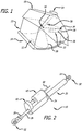
- the lift assist mechanism is secured to the stowage bin support structure and to the track that is attached to the stowage bin.
- the assist mechanism is shown in its compressed state providing no assist.
- FIG. 6 when the stowage bin or other movable component is moved to the lowered or open position, the lift assist mechanism slides along the track until it stops at the end of the track. This acts as a "soft" stop for an empty stowage bin. Loading contents into the stowage bin will further compress the spring in the assist mechanism, and will release the spring lock that allows the assist to be activated with switch.
- the stowage bin or other movable component can be closed with a lift assist, such as when items are loaded into the stowage bin or other movable component, and the lift assist spring mechanism is compressed past its empty-weight position.
- Activating the switch 52 disengages the mechanism lock, and allows the spring to fully assist the stowage bin to its closed position.
- the spring lock is a mechanically operating latch motion dampening mechanism 60 that is releasably connectable with the second end of the spring shaft.
- a spring shaft collar 62 is provided on the second end of the spring shaft, and an overcentering lock pawl 64 is releasably connectable with the spring shaft collar on the second end of the spring shaft.
- a rocker arm 70 has a first end 72 and a second end 74, and the rocker arm is rotatably mounted to the second end of the lift assist spring for movement between a first position 76 and a second position 78.
- the second end of the rocker arm is preferably disposed adjacent to the spring shaft collar on the second end of the spring shaft.
- a buffered return spring 80 is connected to the rocker arm, and an overcenter spring 82 is connected between the first end of the rocker arm and the overcentering lock pawl.
- the buffered return spring biases the rocker arm and overcenter spring to cause the overcentering lock pawl into engagement with the spring shaft collar on the spring shaft when the overcentering lock pawl is in a latched configuration 84, and the spring shaft collar biases the rocker and overcenter spring to cause the overcentering lock pawl to move out of engagement with the spring shaft collar on spring shaft when the overcentering lock pawl is in an unlatched configuration 86.
- the buffered return spring is preferably configured to delay engagement of the overcentering lock pawl as the rocker arm rotates under pressure from the buffered return spring.
- FIG. 8A illustrating a slow release from a latched configuration
- the buffered return spring pushes the rocker arm clockwise, and the overcentering lock pawl is urged into engagement with the spring shaft collar on the spring shaft.
- FIG. 8B illustrating a full loading of the lift assist mechanism in the unlatched configuration, the spring shaft collar pushes the rocker arm counterclockwise, and the overcentering lock pawl is urged out of engagement with the spring shaft collar.
- FIG. 8C illustrating a quick lift from an unlatched configuration
- the buffered return spring can delay engagement of the overcentering lock pawl as the rocker arm rotates under pressure from buffered return spring.
Landscapes
- Engineering & Computer Science (AREA)
- General Engineering & Computer Science (AREA)
- Mechanical Engineering (AREA)
- Chemical & Material Sciences (AREA)
- Combustion & Propulsion (AREA)
- Aviation & Aerospace Engineering (AREA)
- Lock And Its Accessories (AREA)
- Invalid Beds And Related Equipment (AREA)
Claims (10)
- Hebeunterstützungsmechanismus (10) zum Bereitstellen einer Hebeunterstützung für ein bewegliches Bauteil (12), das zwischen einer abgesenkten (14) und einer angehobenen (16) Position relativ zu einer feststehenden Struktur (18) bewegt werden kann, wobei der Hebeunterstützungsmechanismus (10) eine Hebeunterstützungsfeder (20), die ein erstes Ende (22) und ein zweites Ende (24) aufweist, wobei die Hebeunterstützungsfeder (20) zusammengedrückt ist, wenn das bewegliche Bauteil (12) in der abgesenkten Position ist, und nicht zusammengedrückt ist, wenn das bewegliche Bauteil (12) in der angehobenen Position ist, eine Federwelle (26), die ein erstes Ende, das mit dem zweiten Ende (24) der Hebeunterstützungsfeder (20) verbunden ist und sich davon erstreckt, und ein zweites Ende (28) aufweist, und ein Federschloss (40) einschließt, das mit dem zweiten Ende (24) der Hebeunterstützungsfeder (20) verbunden ist, wobei das Federschloss (40) eine verriegelte Ausgestaltung (42) und eine entriegelte Ausgestaltung (44) aufweist, wobei das Federschloss (40) dazu ausgestaltet ist, eine Bewegung der Federwelle (26) in die verriegelte Ausgestaltung zu verhindern, wenn eine Hebeunterstützung des beweglichen Bauteils (12) nicht erforderlich ist, und die Federwelle (26) in die entriegelte Ausgestaltung (44) freizugeben, wenn eine Hebeunterstützung des beweglichen Bauteils (12) erforderlich ist, wobei der Hebemechanismus (10) durch Folgendes gekennzeichnet ist:eine längliche Bahn (34), die entweder in dem beweglichen Bauteil (12) oder in der feststehenden Struktur (18) definiert ist, wobei die längliche Bahn (34) ein erstes und ein zweites Ende (36, 38) aufweist, und wobei entweder das erste Ende (22) der Hebeunterstützungsfeder (20) oder das zweite Ende (28) der Federwelle (26) beweglich mit der Bahn (34) für eine Bewegung zwischen dem ersten und dem zweiten Ende (36, 38) der länglichen Bahn (34) in Eingriff ist;wobei das Federschloss (40) einen Riegelbewegungsdämpfmechanismus (60) aufweist, der lösbar mit dem zweiten Ende (38) der Federwelle (26) verbindbar ist,wobei der Riegelbewegungsdämpfmechanismus (60) einen Federwellenkragen (50) an dem zweiten Ende (38) der Federwelle (26), eine Übertotpunkt-Verriegelungsklinke (64), die lösbar mit dem Federwellenkragen (50) an dem zweiten Ende (28) der Federwelle (26) verbindbar ist, wobei die Übertotpunkt-Verriegelungsklinke (64) eine verriegelte Ausgestaltung (84) und eine entriegelte Ausgestaltung (86) aufweist, einen Kipphebel (70), der ein erstes Ende (72) und ein zweites Ende (74) aufweist, wobei der Kipphebel (70) drehbar an dem zweiten Ende (24) der Hebeunterstützungsfeder (20) für eine Bewegung zwischen einer ersten Position (76) und einer zweiten Position (78) befestigt ist, wobei das zweite Ende (74) des Kipphebels (70) angrenzend an den Federwellenkragen (50) an dem zweiten Ende (28) der Federwelle (26) angeordnet ist, eine gepufferte Rückholfeder (80), die mit dem Kipphebel (70) verbunden ist, und eine Übertotpunkt-Feder (82) einschließt, die zwischen dem ersten Ende (72) des Kipphebels (70) und der Übertotpunkt-Verriegelungsklinke (64) verbunden ist, wobei die gepufferte Rückholfeder (80) den Kipphebel (70) und die Übertotpunkt-Feder (82) vorspannt, um die Übertotpunkt-Verriegelungsklinke (64) in Eingriff mit dem Federwellenkragen (50) an der Federwelle (26) zu bringen, wenn die Übertotpunkt-Verriegelungsklinke (64) in der verriegelten Ausgestaltung (84) ist, und der Federwellenkragen (50) den Kipphebel und die Übertotpunkt-Feder (82) vorspannt, um zu verursachen, dass die Übertotpunkt-Klinke (64) aus dem Eingriff mit dem Federwellenkragen (50) an der Federwelle (26) gebracht wird, wenn die Übertotpunkt-Verriegelungsklinke (64) in der entriegelten Ausgestaltung (86) ist.
- Hebeunterstützungsmechanismus (10) nach Anspruch 1, wobei das bewegliche Bauteil (12) ein Staufach aufweist und ferner einen Schalter (52) aufweist, der dazu ausgestaltet ist, das Federschloss (40) in der entriegelten Ausgestaltung zu halten, wenn das Staufach von der abgesenkten Position in die angehobene Position angehoben wird.
- Hebeunterstützungsmechanismus (10) nach Anspruch 1, wobei das bewegliche Bauteil (12) ein Staufach aufweist, und wobei die gepufferte Rückholfeder (80) einen Zeitverzögerungsmechanismus bereitstellt, um das Federschloss (40) in der entriegelten Ausgestaltung zu halten, wenn das Staufach von der abgesenkten Position in die angehobene Position angehoben wird.
- Hebeunterstützungsmechanismus (10) nach Anspruch 1, wobei das erste Ende der Hebeunterstützungsfeder (20) ein Endlager aufweist.
- Hebeunterstützungsmechanismus (10) nach Anspruch 1, wobei das zweite Ende der Federwelle (26) ein Endlager aufweist.
- Hebeunterstützungsmechanismus (10) nach Anspruch 1, wobei die Hebeunterstützungsfeder (20) eine Gasfeder aufweist.
- Hebeunterstützungsmechanismus (10) nach Anspruch 1, wobei die Hebeunterstützungsfeder (20) eine mechanische Feder aufweist.
- Hebeunterstützungsmechanismus (10) nach Anspruch 1, wobei das Federschloss (40) Folgendes aufweist:eine Verriegelungsklinke (46), die dazu ausgestaltet ist, die Federwelle (26) lösbar in Eingriff zu nehmen;ein Solenoid (48), das mit der Verriegelungsklinke (46) verbunden ist und dazu ausgestaltet ist, zu verursachen, dass die Verriegelungsklinke (46) verriegelt und die Bewegung der Federwelle (26) verhindert wird, wenn eine Hebeunterstützung des beweglichen Bauteils (12) nicht erforderlich ist, und zu verursachen, dass die Verriegelungsklinke (46) entriegelt und die Federwelle (26) zur Bewegung der Federwelle (26) freigegeben wird, wenn die Hebeunterstützung erforderlich ist; undeinen Federwellenkragen (50), der an der Federwelle (26) angeordnet ist, wobei der Federwellenkragen (50) gegen die Verriegelungsklinke (46), die mit der Federwelle (26) in Eingriff ist, geladen ist, um zu verhindern, dass das Solenoid (48) den Mechanismus entriegelt, wenn das bewegliche Bauteil (12) in der angehobenen Position ist und eine Hebeunterstützung des beweglichen Bauteils (12) nicht erforderlich ist, und der Federwellenkragen (50) von der Verriegelungsklinke (46) durch die Hebeunterstützungsfeder (20) weggedrückt wird, wenn das bewegliche Bauteil (12) in der abgesenkten Position ist und eine Hebeunterstützung des beweglichen Bauteils (12) erforderlich ist, wodurch ermöglicht wird, dass die Verriegelungsklinke (46) aus dem Eingriff mit der Federwelle (26) durch das Solenoid (48) gebracht wird.
- Hebeunterstützungsmechanismus (10) nach Anspruch 1, wobei die gepufferte Rückholfeder (80) dazu ausgestaltet ist, den Eingriff der Übertotpunkt-Verriegelungsklinke (64) zu verzögern, wenn sich der Kipphebel unter Druck von der gepufferten Rückholfeder (80) dreht.
- Hebeunterstützungsmechanismus (10) nach Anspruch 8, wobei das bewegliche Bauteil (12) einen Staubehälterabschnitt aufweist, und die feststehende Struktur eine feststehende Behälterabstützstruktur aufweist, und wobei der Staubehälterabschnitt mit einer feststehenden Behälterabstüzstruktur für eine Bewegung des Staubehälterabschnitts zwischen der abgesenkten und der angehobenen Position (14, 16) relativ zur feststehenden Abstützstruktur wirkverbunden ist, und das ferner Folgendes aufweist:einen Schalter (52), der dazu ausgestaltet ist, das Solenoid (48) zu betreiben;eine elektrische Verbindung (54, 58), die dazu ausgestaltet ist, elektrische Leistung von einem elektrischen Flugzeugsystem zu erhalten, und wobei der Schalter (52) dazu ausgestaltet ist, die elektrische Leistung von der elektrischen Verbindung (54, 58) zum Betreiben des Solenoids (48) zu empfangen.
Applications Claiming Priority (3)
| Application Number | Priority Date | Filing Date | Title |
|---|---|---|---|
| US32617810P | 2010-04-20 | 2010-04-20 | |
| US13/089,248 US8943751B2 (en) | 2010-04-20 | 2011-04-18 | Lift assist mechanism |
| PCT/US2011/033127 WO2011133601A2 (en) | 2010-04-20 | 2011-04-19 | Lift assist mechanism |
Publications (2)
| Publication Number | Publication Date |
|---|---|
| EP2560873A2 EP2560873A2 (de) | 2013-02-27 |
| EP2560873B1 true EP2560873B1 (de) | 2017-06-07 |
Family
ID=44504134
Family Applications (1)
| Application Number | Title | Priority Date | Filing Date |
|---|---|---|---|
| EP11717866.5A Not-in-force EP2560873B1 (de) | 2010-04-20 | 2011-04-19 | Hebeunterstützungsmechanismus |
Country Status (7)
| Country | Link |
|---|---|
| US (2) | US8943751B2 (de) |
| EP (1) | EP2560873B1 (de) |
| JP (1) | JP5638689B2 (de) |
| CN (1) | CN102939241B (de) |
| AU (2) | AU2011242834A1 (de) |
| CA (1) | CA2796854C (de) |
| WO (1) | WO2011133601A2 (de) |
Families Citing this family (23)
| Publication number | Priority date | Publication date | Assignee | Title |
|---|---|---|---|---|
| US8770515B1 (en) * | 2010-06-02 | 2014-07-08 | The Boeing Company | Movement assistance system for a storage bin |
| US8955805B2 (en) * | 2012-02-14 | 2015-02-17 | C&D Zodiac, Inc. | Pivot bin assembly |
| DE102012004337B4 (de) | 2012-03-07 | 2014-02-06 | General Aerospace GmbH | Verriegelungsvorrichtung |
| US9629454B2 (en) | 2012-03-27 | 2017-04-25 | Dropout Cabinet Fixtures, Llc | Storage system |
| US9788649B2 (en) | 2012-03-27 | 2017-10-17 | Dropout Cabinet Fixtures, Llc | Storage system |
| CA2931576C (en) * | 2013-02-12 | 2018-05-29 | C&D Zodiac, Inc. | Pivot bin assembly |
| DE102013003364B4 (de) | 2013-03-01 | 2019-01-31 | General Aerospace GmbH | Kraftunterstützungsvorrichtung |
| US9296479B1 (en) * | 2014-09-11 | 2016-03-29 | The Boeing Company | Stowage bin with closing force assistance |
| RU2669496C1 (ru) * | 2014-10-27 | 2018-10-11 | Си Энд Ди ЗОДИАК, ИНК. | Система защелок верхнего багажного отсека |
| AT516642A1 (de) * | 2014-12-15 | 2016-07-15 | Facc Ag | Elektrisch betätigbares bewegbares Überkopf-Gepäckfach für Flugzeuge |
| FR3033614B1 (fr) * | 2015-03-13 | 2022-07-22 | Zodiac Actuation Systems | Actionneur lineaire d'assistance pour manipulation d'un compartiment a bagages, et compartiment a bagages correspondant |
| AT517286B1 (de) * | 2015-05-22 | 2020-12-15 | Facc Ag | Überkopf-Gepäckfach für ein Flugzeug |
| AT517810A1 (de) * | 2015-09-18 | 2017-04-15 | Facc Ag | Überkopf-Gepäckfach |
| US10315768B2 (en) | 2015-11-03 | 2019-06-11 | Facc Ag | Overhead luggage compartment for an aircraft |
| EP3529152B1 (de) * | 2016-10-21 | 2022-07-20 | Facc Ag | Überkopf-gepäckfach für ein flugzeug |
| HRP20221213T1 (hr) * | 2017-01-23 | 2022-12-09 | C&D Zodiac, Inc. | Zakretni spremnik sa sklopom za pomoć pri dizanju i način njegove uporabe |
| DE102017003051A1 (de) | 2017-03-29 | 2018-10-04 | Diehl Aviation Laupheim Gmbh | Überkopfstaufach für ein Passagierflugzeug |
| US10836492B2 (en) * | 2017-03-30 | 2020-11-17 | Itt Manufacturing Enterprises Llc | Load adaptive lift assist for pivoting stowage bin |
| CN112166072B (zh) * | 2018-04-04 | 2024-08-09 | 赛峰客舱公司 | 固装箱铰链系统 |
| JP2020196328A (ja) | 2019-05-31 | 2020-12-10 | デルタ工業株式会社 | リンク機構、乗物の上部収容棚構造及びシートサスペンション機構 |
| DE102021000122A1 (de) * | 2021-01-14 | 2022-07-14 | Johannes Geng | Automatische Kraftunterstützungsvorrichtung |
| DE102023117787A1 (de) * | 2023-07-06 | 2025-01-09 | Diehl Aviation Laupheim Gmbh | Zuschaltung einer Kraftunterstützung für ein Flugzeug-Staufach |
| FR3163345A1 (fr) * | 2024-06-18 | 2025-12-19 | Latecoere | Assistance à l’ouverture d’une porte d’aéronef. |
Family Cites Families (20)
| Publication number | Priority date | Publication date | Assignee | Title |
|---|---|---|---|---|
| US3773311A (en) * | 1971-09-27 | 1973-11-20 | Hartwell Corp | Overhead door control device |
| US5169113A (en) * | 1990-11-07 | 1992-12-08 | Sears Manufacturing Company | Apparatus for controlling and protecting a vehicle seat suspension |
| DE4130644A1 (de) * | 1991-09-14 | 1993-03-18 | Airbus Gmbh | Ueberkopf-gepaeckablage mit einer absenkbaren schale, insbesondere fuer ein passagierflugzeug |
| US5456529A (en) * | 1993-12-30 | 1995-10-10 | The Boeing Company | Powered overhead stowage bin |
| US5567028A (en) | 1995-02-27 | 1996-10-22 | The Boeing Company | Mechanism for translating storage bin |
| US6622965B1 (en) * | 1999-12-20 | 2003-09-23 | Interami Ltd. | Aircraft luggage rack |
| US6343828B1 (en) * | 2000-07-10 | 2002-02-05 | David C. Young | Truck lid hinge and opener system |
| EP1260434B1 (de) * | 2001-05-24 | 2004-07-14 | Heath Tecna Inc. | Entlastungsvorrichtung für eine obere Gepäckablage |
| AT413812B (de) * | 2001-10-17 | 2006-06-15 | Fischer Adv Components Gmbh | Aufhängevorrichtung für absenkbare gebäckablagebehälter |
| ATE295802T1 (de) * | 2001-10-26 | 2005-06-15 | Heath Tecna Inc | Variable entlastungsvorrichtung für eine obere gepäckablage |
| DE10222125A1 (de) * | 2002-05-17 | 2003-11-27 | Aircabin Gmbh | Kraftunterstützungsmodul zur Bereitstellung einer lastabhängigen Unterstützungskraft |
| JP4175951B2 (ja) * | 2003-05-22 | 2008-11-05 | 本田技研工業株式会社 | 車両用開閉体の開閉駆動装置 |
| DE102004049700B4 (de) * | 2004-10-12 | 2007-10-18 | Aircabin Gmbh | Kraftunterstützungsvorrichtung mit lastabhängiger Kraftunterstützung |
| DE102005033259B4 (de) * | 2005-07-15 | 2012-03-08 | Airbus Operations Gmbh | Notöffnungsvorrichtung für ein Gepäckfach mit einer absenkbaren Schale |
| US7893645B2 (en) * | 2006-08-25 | 2011-02-22 | The Boeing Company | System and method for compartment control |
| US20080078871A1 (en) | 2006-08-25 | 2008-04-03 | The Boeing Company | System and method for electronically latching compartments |
| US7887008B2 (en) * | 2006-08-25 | 2011-02-15 | The Boeing Company | System and method for a power-assisted compartment |
| DE102006045189B4 (de) * | 2006-09-25 | 2008-11-27 | Airbus Deutschland Gmbh | Kraftunterstützungssystem |
| US7762737B2 (en) * | 2006-11-09 | 2010-07-27 | The Boeing Company | System and method for stowage compartment pivot assembly |
| DE102007003363B4 (de) * | 2007-01-23 | 2012-09-06 | Stabilus Gmbh | Kraftunterstützungsvorrichtung |
-
2011
- 2011-04-18 US US13/089,248 patent/US8943751B2/en not_active Expired - Fee Related
- 2011-04-19 CA CA2796854A patent/CA2796854C/en not_active Expired - Fee Related
- 2011-04-19 CN CN201180019854.9A patent/CN102939241B/zh not_active Expired - Fee Related
- 2011-04-19 WO PCT/US2011/033127 patent/WO2011133601A2/en not_active Ceased
- 2011-04-19 JP JP2013506250A patent/JP5638689B2/ja not_active Expired - Fee Related
- 2011-04-19 EP EP11717866.5A patent/EP2560873B1/de not_active Not-in-force
- 2011-04-19 AU AU2011242834A patent/AU2011242834A1/en not_active Abandoned
-
2015
- 2015-01-13 US US14/595,952 patent/US9457906B2/en not_active Expired - Fee Related
-
2016
- 2016-08-15 AU AU2016216526A patent/AU2016216526B2/en not_active Ceased
Also Published As
| Publication number | Publication date |
|---|---|
| JP5638689B2 (ja) | 2014-12-10 |
| CA2796854C (en) | 2018-05-22 |
| US8943751B2 (en) | 2015-02-03 |
| WO2011133601A2 (en) | 2011-10-27 |
| AU2011242834A1 (en) | 2012-11-29 |
| JP2013525182A (ja) | 2013-06-20 |
| AU2016216526B2 (en) | 2018-01-04 |
| AU2016216526A1 (en) | 2016-09-01 |
| US20110253714A1 (en) | 2011-10-20 |
| EP2560873A2 (de) | 2013-02-27 |
| CN102939241B (zh) | 2015-07-01 |
| US9457906B2 (en) | 2016-10-04 |
| US20150123526A1 (en) | 2015-05-07 |
| CN102939241A (zh) | 2013-02-20 |
| WO2011133601A3 (en) | 2011-12-22 |
| CA2796854A1 (en) | 2011-10-27 |
Similar Documents
| Publication | Publication Date | Title |
|---|---|---|
| EP2560873B1 (de) | Hebeunterstützungsmechanismus | |
| US8665119B2 (en) | Electrically activated latch for aircraft stowage bins | |
| EP2830941B1 (de) | Flugzeugbordküchenverriegelungen und dichtungssystem | |
| US8201777B2 (en) | Aircraft door and method for using the same | |
| US6691951B2 (en) | Variable load assist mechanism for an overhead bin | |
| US20160083071A1 (en) | Actuator system for an actuatable door and an aircraft having such an actuatable door | |
| US4637642A (en) | Stowage bin latch assembly | |
| CN108025812B (zh) | 头顶行李舱 | |
| US20210025212A1 (en) | Electromechanical door system for an aircraft | |
| GB2408066A (en) | Latch comprising emergency release actuator | |
| CN112239031B (zh) | 顶盖及包括其的集装箱 | |
| CN115556918A (zh) | 飞机舱门增压预防装置 | |
| AU2011242824A1 (en) | Electrically activated latch for aircraft stowage bins | |
| HK1139632B (en) | Aircraft cargo door | |
| HK1139632A (en) | Aircraft cargo door |
Legal Events
| Date | Code | Title | Description |
|---|---|---|---|
| PUAI | Public reference made under article 153(3) epc to a published international application that has entered the european phase |
Free format text: ORIGINAL CODE: 0009012 |
|
| 17P | Request for examination filed |
Effective date: 20121106 |
|
| AK | Designated contracting states |
Kind code of ref document: A2 Designated state(s): AL AT BE BG CH CY CZ DE DK EE ES FI FR GB GR HR HU IE IS IT LI LT LU LV MC MK MT NL NO PL PT RO RS SE SI SK SM TR |
|
| DAX | Request for extension of the european patent (deleted) | ||
| GRAP | Despatch of communication of intention to grant a patent |
Free format text: ORIGINAL CODE: EPIDOSNIGR1 |
|
| STAA | Information on the status of an ep patent application or granted ep patent |
Free format text: STATUS: GRANT OF PATENT IS INTENDED |
|
| INTG | Intention to grant announced |
Effective date: 20161219 |
|
| GRAS | Grant fee paid |
Free format text: ORIGINAL CODE: EPIDOSNIGR3 |
|
| GRAA | (expected) grant |
Free format text: ORIGINAL CODE: 0009210 |
|
| STAA | Information on the status of an ep patent application or granted ep patent |
Free format text: STATUS: THE PATENT HAS BEEN GRANTED |
|
| AK | Designated contracting states |
Kind code of ref document: B1 Designated state(s): AL AT BE BG CH CY CZ DE DK EE ES FI FR GB GR HR HU IE IS IT LI LT LU LV MC MK MT NL NO PL PT RO RS SE SI SK SM TR |
|
| REG | Reference to a national code |
Ref country code: GB Ref legal event code: FG4D |
|
| GRAA | (expected) grant |
Free format text: ORIGINAL CODE: 0009210 |
|
| REG | Reference to a national code |
Ref country code: CH Ref legal event code: EP Ref country code: AT Ref legal event code: REF Ref document number: 899026 Country of ref document: AT Kind code of ref document: T Effective date: 20170615 |
|
| REG | Reference to a national code |
Ref country code: IE Ref legal event code: FG4D |
|
| REG | Reference to a national code |
Ref country code: DE Ref legal event code: R096 Ref document number: 602011038503 Country of ref document: DE |
|
| REG | Reference to a national code |
Ref country code: NL Ref legal event code: MP Effective date: 20170607 |
|
| REG | Reference to a national code |
Ref country code: LT Ref legal event code: MG4D |
|
| PG25 | Lapsed in a contracting state [announced via postgrant information from national office to epo] |
Ref country code: NO Free format text: LAPSE BECAUSE OF FAILURE TO SUBMIT A TRANSLATION OF THE DESCRIPTION OR TO PAY THE FEE WITHIN THE PRESCRIBED TIME-LIMIT Effective date: 20170907 Ref country code: ES Free format text: LAPSE BECAUSE OF FAILURE TO SUBMIT A TRANSLATION OF THE DESCRIPTION OR TO PAY THE FEE WITHIN THE PRESCRIBED TIME-LIMIT Effective date: 20170607 Ref country code: GR Free format text: LAPSE BECAUSE OF FAILURE TO SUBMIT A TRANSLATION OF THE DESCRIPTION OR TO PAY THE FEE WITHIN THE PRESCRIBED TIME-LIMIT Effective date: 20170908 Ref country code: HR Free format text: LAPSE BECAUSE OF FAILURE TO SUBMIT A TRANSLATION OF THE DESCRIPTION OR TO PAY THE FEE WITHIN THE PRESCRIBED TIME-LIMIT Effective date: 20170607 Ref country code: FI Free format text: LAPSE BECAUSE OF FAILURE TO SUBMIT A TRANSLATION OF THE DESCRIPTION OR TO PAY THE FEE WITHIN THE PRESCRIBED TIME-LIMIT Effective date: 20170607 Ref country code: LT Free format text: LAPSE BECAUSE OF FAILURE TO SUBMIT A TRANSLATION OF THE DESCRIPTION OR TO PAY THE FEE WITHIN THE PRESCRIBED TIME-LIMIT Effective date: 20170607 |
|
| REG | Reference to a national code |
Ref country code: AT Ref legal event code: MK05 Ref document number: 899026 Country of ref document: AT Kind code of ref document: T Effective date: 20170607 |
|
| PG25 | Lapsed in a contracting state [announced via postgrant information from national office to epo] |
Ref country code: SE Free format text: LAPSE BECAUSE OF FAILURE TO SUBMIT A TRANSLATION OF THE DESCRIPTION OR TO PAY THE FEE WITHIN THE PRESCRIBED TIME-LIMIT Effective date: 20170607 Ref country code: LV Free format text: LAPSE BECAUSE OF FAILURE TO SUBMIT A TRANSLATION OF THE DESCRIPTION OR TO PAY THE FEE WITHIN THE PRESCRIBED TIME-LIMIT Effective date: 20170607 Ref country code: NL Free format text: LAPSE BECAUSE OF FAILURE TO SUBMIT A TRANSLATION OF THE DESCRIPTION OR TO PAY THE FEE WITHIN THE PRESCRIBED TIME-LIMIT Effective date: 20170607 Ref country code: RS Free format text: LAPSE BECAUSE OF FAILURE TO SUBMIT A TRANSLATION OF THE DESCRIPTION OR TO PAY THE FEE WITHIN THE PRESCRIBED TIME-LIMIT Effective date: 20170607 Ref country code: BG Free format text: LAPSE BECAUSE OF FAILURE TO SUBMIT A TRANSLATION OF THE DESCRIPTION OR TO PAY THE FEE WITHIN THE PRESCRIBED TIME-LIMIT Effective date: 20170907 |
|
| PG25 | Lapsed in a contracting state [announced via postgrant information from national office to epo] |
Ref country code: RO Free format text: LAPSE BECAUSE OF FAILURE TO SUBMIT A TRANSLATION OF THE DESCRIPTION OR TO PAY THE FEE WITHIN THE PRESCRIBED TIME-LIMIT Effective date: 20170607 Ref country code: EE Free format text: LAPSE BECAUSE OF FAILURE TO SUBMIT A TRANSLATION OF THE DESCRIPTION OR TO PAY THE FEE WITHIN THE PRESCRIBED TIME-LIMIT Effective date: 20170607 Ref country code: AT Free format text: LAPSE BECAUSE OF FAILURE TO SUBMIT A TRANSLATION OF THE DESCRIPTION OR TO PAY THE FEE WITHIN THE PRESCRIBED TIME-LIMIT Effective date: 20170607 Ref country code: SK Free format text: LAPSE BECAUSE OF FAILURE TO SUBMIT A TRANSLATION OF THE DESCRIPTION OR TO PAY THE FEE WITHIN THE PRESCRIBED TIME-LIMIT Effective date: 20170607 Ref country code: CZ Free format text: LAPSE BECAUSE OF FAILURE TO SUBMIT A TRANSLATION OF THE DESCRIPTION OR TO PAY THE FEE WITHIN THE PRESCRIBED TIME-LIMIT Effective date: 20170607 |
|
| PG25 | Lapsed in a contracting state [announced via postgrant information from national office to epo] |
Ref country code: IT Free format text: LAPSE BECAUSE OF FAILURE TO SUBMIT A TRANSLATION OF THE DESCRIPTION OR TO PAY THE FEE WITHIN THE PRESCRIBED TIME-LIMIT Effective date: 20170607 Ref country code: IS Free format text: LAPSE BECAUSE OF FAILURE TO SUBMIT A TRANSLATION OF THE DESCRIPTION OR TO PAY THE FEE WITHIN THE PRESCRIBED TIME-LIMIT Effective date: 20171007 Ref country code: SM Free format text: LAPSE BECAUSE OF FAILURE TO SUBMIT A TRANSLATION OF THE DESCRIPTION OR TO PAY THE FEE WITHIN THE PRESCRIBED TIME-LIMIT Effective date: 20170607 Ref country code: PL Free format text: LAPSE BECAUSE OF FAILURE TO SUBMIT A TRANSLATION OF THE DESCRIPTION OR TO PAY THE FEE WITHIN THE PRESCRIBED TIME-LIMIT Effective date: 20170607 |
|
| REG | Reference to a national code |
Ref country code: DE Ref legal event code: R097 Ref document number: 602011038503 Country of ref document: DE |
|
| PLBE | No opposition filed within time limit |
Free format text: ORIGINAL CODE: 0009261 |
|
| STAA | Information on the status of an ep patent application or granted ep patent |
Free format text: STATUS: NO OPPOSITION FILED WITHIN TIME LIMIT |
|
| REG | Reference to a national code |
Ref country code: FR Ref legal event code: PLFP Year of fee payment: 8 |
|
| PG25 | Lapsed in a contracting state [announced via postgrant information from national office to epo] |
Ref country code: DK Free format text: LAPSE BECAUSE OF FAILURE TO SUBMIT A TRANSLATION OF THE DESCRIPTION OR TO PAY THE FEE WITHIN THE PRESCRIBED TIME-LIMIT Effective date: 20170607 |
|
| 26N | No opposition filed |
Effective date: 20180308 |
|
| PG25 | Lapsed in a contracting state [announced via postgrant information from national office to epo] |
Ref country code: SI Free format text: LAPSE BECAUSE OF FAILURE TO SUBMIT A TRANSLATION OF THE DESCRIPTION OR TO PAY THE FEE WITHIN THE PRESCRIBED TIME-LIMIT Effective date: 20170607 |
|
| PG25 | Lapsed in a contracting state [announced via postgrant information from national office to epo] |
Ref country code: MC Free format text: LAPSE BECAUSE OF FAILURE TO SUBMIT A TRANSLATION OF THE DESCRIPTION OR TO PAY THE FEE WITHIN THE PRESCRIBED TIME-LIMIT Effective date: 20170607 |
|
| REG | Reference to a national code |
Ref country code: CH Ref legal event code: PL |
|
| REG | Reference to a national code |
Ref country code: BE Ref legal event code: MM Effective date: 20180430 |
|
| REG | Reference to a national code |
Ref country code: IE Ref legal event code: MM4A |
|
| PG25 | Lapsed in a contracting state [announced via postgrant information from national office to epo] |
Ref country code: LU Free format text: LAPSE BECAUSE OF NON-PAYMENT OF DUE FEES Effective date: 20180419 |
|
| PG25 | Lapsed in a contracting state [announced via postgrant information from national office to epo] |
Ref country code: BE Free format text: LAPSE BECAUSE OF NON-PAYMENT OF DUE FEES Effective date: 20180430 Ref country code: LI Free format text: LAPSE BECAUSE OF NON-PAYMENT OF DUE FEES Effective date: 20180430 Ref country code: CH Free format text: LAPSE BECAUSE OF NON-PAYMENT OF DUE FEES Effective date: 20180430 |
|
| PG25 | Lapsed in a contracting state [announced via postgrant information from national office to epo] |
Ref country code: IE Free format text: LAPSE BECAUSE OF NON-PAYMENT OF DUE FEES Effective date: 20180419 |
|
| PG25 | Lapsed in a contracting state [announced via postgrant information from national office to epo] |
Ref country code: MT Free format text: LAPSE BECAUSE OF NON-PAYMENT OF DUE FEES Effective date: 20180419 |
|
| PG25 | Lapsed in a contracting state [announced via postgrant information from national office to epo] |
Ref country code: TR Free format text: LAPSE BECAUSE OF FAILURE TO SUBMIT A TRANSLATION OF THE DESCRIPTION OR TO PAY THE FEE WITHIN THE PRESCRIBED TIME-LIMIT Effective date: 20170607 |
|
| PGFP | Annual fee paid to national office [announced via postgrant information from national office to epo] |
Ref country code: GB Payment date: 20200323 Year of fee payment: 10 |
|
| PG25 | Lapsed in a contracting state [announced via postgrant information from national office to epo] |
Ref country code: HU Free format text: LAPSE BECAUSE OF FAILURE TO SUBMIT A TRANSLATION OF THE DESCRIPTION OR TO PAY THE FEE WITHIN THE PRESCRIBED TIME-LIMIT; INVALID AB INITIO Effective date: 20110419 Ref country code: PT Free format text: LAPSE BECAUSE OF FAILURE TO SUBMIT A TRANSLATION OF THE DESCRIPTION OR TO PAY THE FEE WITHIN THE PRESCRIBED TIME-LIMIT Effective date: 20170607 |
|
| PG25 | Lapsed in a contracting state [announced via postgrant information from national office to epo] |
Ref country code: MK Free format text: LAPSE BECAUSE OF NON-PAYMENT OF DUE FEES Effective date: 20170607 Ref country code: CY Free format text: LAPSE BECAUSE OF FAILURE TO SUBMIT A TRANSLATION OF THE DESCRIPTION OR TO PAY THE FEE WITHIN THE PRESCRIBED TIME-LIMIT Effective date: 20170607 |
|
| PGFP | Annual fee paid to national office [announced via postgrant information from national office to epo] |
Ref country code: FR Payment date: 20200319 Year of fee payment: 10 |
|
| PG25 | Lapsed in a contracting state [announced via postgrant information from national office to epo] |
Ref country code: AL Free format text: LAPSE BECAUSE OF FAILURE TO SUBMIT A TRANSLATION OF THE DESCRIPTION OR TO PAY THE FEE WITHIN THE PRESCRIBED TIME-LIMIT Effective date: 20170607 |
|
| PGFP | Annual fee paid to national office [announced via postgrant information from national office to epo] |
Ref country code: DE Payment date: 20200319 Year of fee payment: 10 |
|
| REG | Reference to a national code |
Ref country code: DE Ref legal event code: R119 Ref document number: 602011038503 Country of ref document: DE |
|
| GBPC | Gb: european patent ceased through non-payment of renewal fee |
Effective date: 20210419 |
|
| PG25 | Lapsed in a contracting state [announced via postgrant information from national office to epo] |
Ref country code: FR Free format text: LAPSE BECAUSE OF NON-PAYMENT OF DUE FEES Effective date: 20210430 Ref country code: GB Free format text: LAPSE BECAUSE OF NON-PAYMENT OF DUE FEES Effective date: 20210419 Ref country code: DE Free format text: LAPSE BECAUSE OF NON-PAYMENT OF DUE FEES Effective date: 20211103 |