EP2558522B1 - Film de polymère à gradient modelé - Google Patents
Film de polymère à gradient modelé Download PDFInfo
- Publication number
- EP2558522B1 EP2558522B1 EP10849988.0A EP10849988A EP2558522B1 EP 2558522 B1 EP2558522 B1 EP 2558522B1 EP 10849988 A EP10849988 A EP 10849988A EP 2558522 B1 EP2558522 B1 EP 2558522B1
- Authority
- EP
- European Patent Office
- Prior art keywords
- gradient
- optical film
- film
- cases
- volume fraction
- Prior art date
- Legal status (The legal status is an assumption and is not a legal conclusion. Google has not performed a legal analysis and makes no representation as to the accuracy of the status listed.)
- Active
Links
- 229920006254 polymer film Polymers 0.000 title claims description 34
- 239000012788 optical film Substances 0.000 claims description 243
- 230000003287 optical effect Effects 0.000 claims description 110
- 239000010408 film Substances 0.000 claims description 71
- 239000000758 substrate Substances 0.000 claims description 64
- 239000000853 adhesive Substances 0.000 claims description 21
- 230000001070 adhesive effect Effects 0.000 claims description 21
- 239000000835 fiber Substances 0.000 claims description 18
- 239000007787 solid Substances 0.000 claims description 15
- 238000010276 construction Methods 0.000 claims description 14
- 229910052751 metal Inorganic materials 0.000 claims description 11
- 239000002184 metal Substances 0.000 claims description 11
- 229920000642 polymer Polymers 0.000 claims description 11
- 230000036961 partial effect Effects 0.000 claims description 9
- 230000003098 cholesteric effect Effects 0.000 claims description 5
- 230000002708 enhancing effect Effects 0.000 claims description 5
- 229920005596 polymer binder Polymers 0.000 claims description 5
- 239000002491 polymer binding agent Substances 0.000 claims description 5
- 238000000605 extraction Methods 0.000 claims description 4
- 238000000576 coating method Methods 0.000 description 104
- 239000002245 particle Substances 0.000 description 101
- 239000011248 coating agent Substances 0.000 description 100
- 238000000034 method Methods 0.000 description 73
- VYPSYNLAJGMNEJ-UHFFFAOYSA-N Silicium dioxide Chemical compound O=[Si]=O VYPSYNLAJGMNEJ-UHFFFAOYSA-N 0.000 description 43
- 239000011230 binding agent Substances 0.000 description 40
- 239000000463 material Substances 0.000 description 35
- 239000010410 layer Substances 0.000 description 34
- ARXJGSRGQADJSQ-UHFFFAOYSA-N 1-methoxypropan-2-ol Chemical compound COCC(C)O ARXJGSRGQADJSQ-UHFFFAOYSA-N 0.000 description 30
- 230000008569 process Effects 0.000 description 30
- 239000002904 solvent Substances 0.000 description 25
- 239000012790 adhesive layer Substances 0.000 description 23
- 238000009826 distribution Methods 0.000 description 21
- 230000005540 biological transmission Effects 0.000 description 19
- 230000007704 transition Effects 0.000 description 18
- 239000011800 void material Substances 0.000 description 17
- 239000011148 porous material Substances 0.000 description 16
- IJGRMHOSHXDMSA-UHFFFAOYSA-N Atomic nitrogen Chemical compound N#N IJGRMHOSHXDMSA-UHFFFAOYSA-N 0.000 description 15
- KFZMGEQAYNKOFK-UHFFFAOYSA-N Isopropanol Chemical compound CC(C)O KFZMGEQAYNKOFK-UHFFFAOYSA-N 0.000 description 15
- 239000000203 mixture Substances 0.000 description 13
- 239000000126 substance Substances 0.000 description 13
- 230000010287 polarization Effects 0.000 description 12
- 239000010453 quartz Substances 0.000 description 12
- 239000000377 silicon dioxide Substances 0.000 description 12
- QVGXLLKOCUKJST-UHFFFAOYSA-N atomic oxygen Chemical compound [O] QVGXLLKOCUKJST-UHFFFAOYSA-N 0.000 description 11
- 229910052760 oxygen Inorganic materials 0.000 description 11
- 239000001301 oxygen Substances 0.000 description 11
- 239000004820 Pressure-sensitive adhesive Substances 0.000 description 10
- 230000004927 fusion Effects 0.000 description 10
- 238000001035 drying Methods 0.000 description 9
- -1 for example Substances 0.000 description 9
- 238000006116 polymerization reaction Methods 0.000 description 9
- 238000003756 stirring Methods 0.000 description 9
- 229910052757 nitrogen Inorganic materials 0.000 description 8
- 238000002834 transmittance Methods 0.000 description 8
- XLYOFNOQVPJJNP-UHFFFAOYSA-N water Substances O XLYOFNOQVPJJNP-UHFFFAOYSA-N 0.000 description 8
- 239000011159 matrix material Substances 0.000 description 7
- 230000005855 radiation Effects 0.000 description 7
- 238000002310 reflectometry Methods 0.000 description 7
- 229910052799 carbon Inorganic materials 0.000 description 6
- 230000002829 reductive effect Effects 0.000 description 6
- 230000002123 temporal effect Effects 0.000 description 6
- 238000011088 calibration curve Methods 0.000 description 5
- 230000008859 change Effects 0.000 description 5
- 229920001296 polysiloxane Polymers 0.000 description 5
- PXHVJJICTQNCMI-UHFFFAOYSA-N Nickel Chemical compound [Ni] PXHVJJICTQNCMI-UHFFFAOYSA-N 0.000 description 4
- BQCADISMDOOEFD-UHFFFAOYSA-N Silver Chemical compound [Ag] BQCADISMDOOEFD-UHFFFAOYSA-N 0.000 description 4
- NIXOWILDQLNWCW-UHFFFAOYSA-N acrylic acid group Chemical group C(C=C)(=O)O NIXOWILDQLNWCW-UHFFFAOYSA-N 0.000 description 4
- 239000006185 dispersion Substances 0.000 description 4
- 239000013335 mesoporous material Substances 0.000 description 4
- 238000000059 patterning Methods 0.000 description 4
- 238000002360 preparation method Methods 0.000 description 4
- 238000002390 rotary evaporation Methods 0.000 description 4
- 229910052709 silver Inorganic materials 0.000 description 4
- 239000004332 silver Substances 0.000 description 4
- QNODIIQQMGDSEF-UHFFFAOYSA-N (1-hydroxycyclohexyl)-phenylmethanone Chemical compound C=1C=CC=CC=1C(=O)C1(O)CCCCC1 QNODIIQQMGDSEF-UHFFFAOYSA-N 0.000 description 3
- LHENQXAPVKABON-UHFFFAOYSA-N 1-methoxypropan-1-ol Chemical compound CCC(O)OC LHENQXAPVKABON-UHFFFAOYSA-N 0.000 description 3
- ZWEHNKRNPOVVGH-UHFFFAOYSA-N 2-Butanone Chemical compound CCC(C)=O ZWEHNKRNPOVVGH-UHFFFAOYSA-N 0.000 description 3
- BLRPTPMANUNPDV-UHFFFAOYSA-N Silane Chemical compound [SiH4] BLRPTPMANUNPDV-UHFFFAOYSA-N 0.000 description 3
- 239000006096 absorbing agent Substances 0.000 description 3
- 238000010521 absorption reaction Methods 0.000 description 3
- 238000001723 curing Methods 0.000 description 3
- 230000007423 decrease Effects 0.000 description 3
- 230000007547 defect Effects 0.000 description 3
- 238000001802 infusion Methods 0.000 description 3
- 230000005764 inhibitory process Effects 0.000 description 3
- 239000004973 liquid crystal related substance Substances 0.000 description 3
- 238000004519 manufacturing process Methods 0.000 description 3
- 230000004048 modification Effects 0.000 description 3
- 238000012986 modification Methods 0.000 description 3
- 230000035515 penetration Effects 0.000 description 3
- 239000004417 polycarbonate Substances 0.000 description 3
- 229920000515 polycarbonate Polymers 0.000 description 3
- XTUSEBKMEQERQV-UHFFFAOYSA-N propan-2-ol;hydrate Chemical compound O.CC(C)O XTUSEBKMEQERQV-UHFFFAOYSA-N 0.000 description 3
- 229910000077 silane Inorganic materials 0.000 description 3
- NIXOWILDQLNWCW-UHFFFAOYSA-M Acrylate Chemical compound [O-]C(=O)C=C NIXOWILDQLNWCW-UHFFFAOYSA-M 0.000 description 2
- 239000004743 Polypropylene Substances 0.000 description 2
- 239000004793 Polystyrene Substances 0.000 description 2
- GWEVSGVZZGPLCZ-UHFFFAOYSA-N Titan oxide Chemical compound O=[Ti]=O GWEVSGVZZGPLCZ-UHFFFAOYSA-N 0.000 description 2
- 229920006397 acrylic thermoplastic Polymers 0.000 description 2
- 239000000654 additive Substances 0.000 description 2
- 238000006243 chemical reaction Methods 0.000 description 2
- 239000008119 colloidal silica Substances 0.000 description 2
- 230000008878 coupling Effects 0.000 description 2
- 238000010168 coupling process Methods 0.000 description 2
- 238000005859 coupling reaction Methods 0.000 description 2
- 230000003247 decreasing effect Effects 0.000 description 2
- 239000007789 gas Substances 0.000 description 2
- 239000011521 glass Substances 0.000 description 2
- 239000010954 inorganic particle Substances 0.000 description 2
- 238000002156 mixing Methods 0.000 description 2
- 239000002105 nanoparticle Substances 0.000 description 2
- 229910052759 nickel Inorganic materials 0.000 description 2
- 239000011146 organic particle Substances 0.000 description 2
- RVTZCBVAJQQJTK-UHFFFAOYSA-N oxygen(2-);zirconium(4+) Chemical compound [O-2].[O-2].[Zr+4] RVTZCBVAJQQJTK-UHFFFAOYSA-N 0.000 description 2
- 229920003229 poly(methyl methacrylate) Polymers 0.000 description 2
- 230000000379 polymerizing effect Effects 0.000 description 2
- 229920000193 polymethacrylate Polymers 0.000 description 2
- 229920001155 polypropylene Polymers 0.000 description 2
- 239000002987 primer (paints) Substances 0.000 description 2
- 238000012545 processing Methods 0.000 description 2
- ISXSCDLOGDJUNJ-UHFFFAOYSA-N tert-butyl prop-2-enoate Chemical compound CC(C)(C)OC(=O)C=C ISXSCDLOGDJUNJ-UHFFFAOYSA-N 0.000 description 2
- 238000012546 transfer Methods 0.000 description 2
- UWSYCPWEBZRZNJ-UHFFFAOYSA-N trimethoxy(2,4,4-trimethylpentyl)silane Chemical compound CO[Si](OC)(OC)CC(C)CC(C)(C)C UWSYCPWEBZRZNJ-UHFFFAOYSA-N 0.000 description 2
- 229910001928 zirconium oxide Inorganic materials 0.000 description 2
- SBASXUCJHJRPEV-UHFFFAOYSA-N 2-(2-methoxyethoxy)ethanol Chemical compound COCCOCCO SBASXUCJHJRPEV-UHFFFAOYSA-N 0.000 description 1
- VGIURMCNTDVGJM-UHFFFAOYSA-N 4-triethoxysilylbutanenitrile Chemical compound CCO[Si](OCC)(OCC)CCCC#N VGIURMCNTDVGJM-UHFFFAOYSA-N 0.000 description 1
- KXDHJXZQYSOELW-UHFFFAOYSA-M Carbamate Chemical compound NC([O-])=O KXDHJXZQYSOELW-UHFFFAOYSA-M 0.000 description 1
- 239000004986 Cholesteric liquid crystals (ChLC) Substances 0.000 description 1
- 244000043261 Hevea brasiliensis Species 0.000 description 1
- 238000004566 IR spectroscopy Methods 0.000 description 1
- 239000004698 Polyethylene Substances 0.000 description 1
- UKLDJPRMSDWDSL-UHFFFAOYSA-L [dibutyl(dodecanoyloxy)stannyl] dodecanoate Chemical compound CCCCCCCCCCCC(=O)O[Sn](CCCC)(CCCC)OC(=O)CCCCCCCCCCC UKLDJPRMSDWDSL-UHFFFAOYSA-L 0.000 description 1
- 238000005299 abrasion Methods 0.000 description 1
- 150000001252 acrylic acid derivatives Chemical class 0.000 description 1
- 239000002318 adhesion promoter Substances 0.000 description 1
- 230000032683 aging Effects 0.000 description 1
- WYTGDNHDOZPMIW-RCBQFDQVSA-N alstonine Natural products C1=CC2=C3C=CC=CC3=NC2=C2N1C[C@H]1[C@H](C)OC=C(C(=O)OC)[C@H]1C2 WYTGDNHDOZPMIW-RCBQFDQVSA-N 0.000 description 1
- 229910052782 aluminium Inorganic materials 0.000 description 1
- XAGFODPZIPBFFR-UHFFFAOYSA-N aluminium Chemical compound [Al] XAGFODPZIPBFFR-UHFFFAOYSA-N 0.000 description 1
- PNEYBMLMFCGWSK-UHFFFAOYSA-N aluminium oxide Inorganic materials [O-2].[O-2].[O-2].[Al+3].[Al+3] PNEYBMLMFCGWSK-UHFFFAOYSA-N 0.000 description 1
- 238000000149 argon plasma sintering Methods 0.000 description 1
- 229920001400 block copolymer Polymers 0.000 description 1
- 239000006229 carbon black Substances 0.000 description 1
- 230000015556 catabolic process Effects 0.000 description 1
- 239000000919 ceramic Substances 0.000 description 1
- 238000001311 chemical methods and process Methods 0.000 description 1
- 239000003795 chemical substances by application Substances 0.000 description 1
- 230000003749 cleanliness Effects 0.000 description 1
- 239000011247 coating layer Substances 0.000 description 1
- 238000001246 colloidal dispersion Methods 0.000 description 1
- 239000003086 colorant Substances 0.000 description 1
- 239000004020 conductor Substances 0.000 description 1
- 239000000356 contaminant Substances 0.000 description 1
- 239000007822 coupling agent Substances 0.000 description 1
- 229920006037 cross link polymer Polymers 0.000 description 1
- 238000006731 degradation reaction Methods 0.000 description 1
- 239000008367 deionised water Substances 0.000 description 1
- 229910021641 deionized water Inorganic materials 0.000 description 1
- 230000001419 dependent effect Effects 0.000 description 1
- 239000012975 dibutyltin dilaurate Substances 0.000 description 1
- 238000009792 diffusion process Methods 0.000 description 1
- 230000009977 dual effect Effects 0.000 description 1
- 229920001971 elastomer Polymers 0.000 description 1
- 230000007613 environmental effect Effects 0.000 description 1
- 238000001704 evaporation Methods 0.000 description 1
- 239000006260 foam Substances 0.000 description 1
- 229910021485 fumed silica Inorganic materials 0.000 description 1
- 238000010438 heat treatment Methods 0.000 description 1
- 238000005286 illumination Methods 0.000 description 1
- AMGQUBHHOARCQH-UHFFFAOYSA-N indium;oxotin Chemical compound [In].[Sn]=O AMGQUBHHOARCQH-UHFFFAOYSA-N 0.000 description 1
- 230000008595 infiltration Effects 0.000 description 1
- 238000001764 infiltration Methods 0.000 description 1
- 239000003112 inhibitor Substances 0.000 description 1
- 230000002401 inhibitory effect Effects 0.000 description 1
- 239000003999 initiator Substances 0.000 description 1
- 230000010354 integration Effects 0.000 description 1
- 230000003993 interaction Effects 0.000 description 1
- 230000001788 irregular Effects 0.000 description 1
- 239000012948 isocyanate Substances 0.000 description 1
- 150000002513 isocyanates Chemical class 0.000 description 1
- 239000007788 liquid Substances 0.000 description 1
- 238000005259 measurement Methods 0.000 description 1
- 150000002739 metals Chemical class 0.000 description 1
- 125000005395 methacrylic acid group Chemical group 0.000 description 1
- 239000000178 monomer Substances 0.000 description 1
- 239000007783 nanoporous material Substances 0.000 description 1
- 229920003052 natural elastomer Polymers 0.000 description 1
- 229920001194 natural rubber Polymers 0.000 description 1
- 150000002829 nitrogen Chemical class 0.000 description 1
- 239000012299 nitrogen atmosphere Substances 0.000 description 1
- 238000001579 optical reflectometry Methods 0.000 description 1
- 239000011049 pearl Substances 0.000 description 1
- 238000005191 phase separation Methods 0.000 description 1
- 230000000704 physical effect Effects 0.000 description 1
- 229920000573 polyethylene Polymers 0.000 description 1
- 239000002861 polymer material Substances 0.000 description 1
- 239000003505 polymerization initiator Substances 0.000 description 1
- 229920000098 polyolefin Polymers 0.000 description 1
- 229920002223 polystyrene Polymers 0.000 description 1
- 229920001289 polyvinyl ether Polymers 0.000 description 1
- 230000009290 primary effect Effects 0.000 description 1
- 239000013615 primer Substances 0.000 description 1
- 230000001737 promoting effect Effects 0.000 description 1
- 239000011347 resin Substances 0.000 description 1
- 229920005989 resin Polymers 0.000 description 1
- 230000000717 retained effect Effects 0.000 description 1
- 239000005060 rubber Substances 0.000 description 1
- 239000000565 sealant Substances 0.000 description 1
- 238000007789 sealing Methods 0.000 description 1
- 239000004065 semiconductor Substances 0.000 description 1
- 241000894007 species Species 0.000 description 1
- 238000001228 spectrum Methods 0.000 description 1
- 229920006132 styrene block copolymer Polymers 0.000 description 1
- 239000002344 surface layer Substances 0.000 description 1
- 239000004094 surface-active agent Substances 0.000 description 1
- 229920003051 synthetic elastomer Polymers 0.000 description 1
- 239000005061 synthetic rubber Substances 0.000 description 1
- 238000003878 thermal aging Methods 0.000 description 1
- 238000005382 thermal cycling Methods 0.000 description 1
- 229920001169 thermoplastic Polymers 0.000 description 1
- 229920002725 thermoplastic elastomer Polymers 0.000 description 1
- 239000004416 thermosoftening plastic Substances 0.000 description 1
- 238000012876 topography Methods 0.000 description 1
- FRGPKMWIYVTFIQ-UHFFFAOYSA-N triethoxy(3-isocyanatopropyl)silane Chemical compound CCO[Si](OCC)(OCC)CCCN=C=O FRGPKMWIYVTFIQ-UHFFFAOYSA-N 0.000 description 1
- 150000003673 urethanes Chemical class 0.000 description 1
Images


Classifications
-
- C—CHEMISTRY; METALLURGY
- C08—ORGANIC MACROMOLECULAR COMPOUNDS; THEIR PREPARATION OR CHEMICAL WORKING-UP; COMPOSITIONS BASED THEREON
- C08J—WORKING-UP; GENERAL PROCESSES OF COMPOUNDING; AFTER-TREATMENT NOT COVERED BY SUBCLASSES C08B, C08C, C08F, C08G or C08H
- C08J5/00—Manufacture of articles or shaped materials containing macromolecular substances
- C08J5/18—Manufacture of films or sheets
-
- G—PHYSICS
- G02—OPTICS
- G02B—OPTICAL ELEMENTS, SYSTEMS OR APPARATUS
- G02B5/00—Optical elements other than lenses
- G02B5/02—Diffusing elements; Afocal elements
- G02B5/0205—Diffusing elements; Afocal elements characterised by the diffusing properties
- G02B5/0263—Diffusing elements; Afocal elements characterised by the diffusing properties with positional variation of the diffusing properties, e.g. gradient or patterned diffuser
-
- B—PERFORMING OPERATIONS; TRANSPORTING
- B05—SPRAYING OR ATOMISING IN GENERAL; APPLYING FLUENT MATERIALS TO SURFACES, IN GENERAL
- B05D—PROCESSES FOR APPLYING FLUENT MATERIALS TO SURFACES, IN GENERAL
- B05D3/00—Pretreatment of surfaces to which liquids or other fluent materials are to be applied; After-treatment of applied coatings, e.g. intermediate treating of an applied coating preparatory to subsequent applications of liquids or other fluent materials
- B05D3/06—Pretreatment of surfaces to which liquids or other fluent materials are to be applied; After-treatment of applied coatings, e.g. intermediate treating of an applied coating preparatory to subsequent applications of liquids or other fluent materials by exposure to radiation
- B05D3/061—Pretreatment of surfaces to which liquids or other fluent materials are to be applied; After-treatment of applied coatings, e.g. intermediate treating of an applied coating preparatory to subsequent applications of liquids or other fluent materials by exposure to radiation using U.V.
- B05D3/065—After-treatment
- B05D3/067—Curing or cross-linking the coating
-
- B—PERFORMING OPERATIONS; TRANSPORTING
- B29—WORKING OF PLASTICS; WORKING OF SUBSTANCES IN A PLASTIC STATE IN GENERAL
- B29C—SHAPING OR JOINING OF PLASTICS; SHAPING OF MATERIAL IN A PLASTIC STATE, NOT OTHERWISE PROVIDED FOR; AFTER-TREATMENT OF THE SHAPED PRODUCTS, e.g. REPAIRING
- B29C41/00—Shaping by coating a mould, core or other substrate, i.e. by depositing material and stripping-off the shaped article; Apparatus therefor
- B29C41/24—Shaping by coating a mould, core or other substrate, i.e. by depositing material and stripping-off the shaped article; Apparatus therefor for making articles of indefinite length
-
- G—PHYSICS
- G02—OPTICS
- G02B—OPTICAL ELEMENTS, SYSTEMS OR APPARATUS
- G02B1/00—Optical elements characterised by the material of which they are made; Optical coatings for optical elements
- G02B1/04—Optical elements characterised by the material of which they are made; Optical coatings for optical elements made of organic materials, e.g. plastics
-
- G—PHYSICS
- G02—OPTICS
- G02B—OPTICAL ELEMENTS, SYSTEMS OR APPARATUS
- G02B5/00—Optical elements other than lenses
- G02B5/02—Diffusing elements; Afocal elements
- G02B5/0205—Diffusing elements; Afocal elements characterised by the diffusing properties
- G02B5/0236—Diffusing elements; Afocal elements characterised by the diffusing properties the diffusion taking place within the volume of the element
- G02B5/0247—Diffusing elements; Afocal elements characterised by the diffusing properties the diffusion taking place within the volume of the element by means of voids or pores
-
- G—PHYSICS
- G02—OPTICS
- G02F—OPTICAL DEVICES OR ARRANGEMENTS FOR THE CONTROL OF LIGHT BY MODIFICATION OF THE OPTICAL PROPERTIES OF THE MEDIA OF THE ELEMENTS INVOLVED THEREIN; NON-LINEAR OPTICS; FREQUENCY-CHANGING OF LIGHT; OPTICAL LOGIC ELEMENTS; OPTICAL ANALOGUE/DIGITAL CONVERTERS
- G02F1/00—Devices or arrangements for the control of the intensity, colour, phase, polarisation or direction of light arriving from an independent light source, e.g. switching, gating or modulating; Non-linear optics
- G02F1/01—Devices or arrangements for the control of the intensity, colour, phase, polarisation or direction of light arriving from an independent light source, e.g. switching, gating or modulating; Non-linear optics for the control of the intensity, phase, polarisation or colour
- G02F1/13—Devices or arrangements for the control of the intensity, colour, phase, polarisation or direction of light arriving from an independent light source, e.g. switching, gating or modulating; Non-linear optics for the control of the intensity, phase, polarisation or colour based on liquid crystals, e.g. single liquid crystal display cells
- G02F1/133—Constructional arrangements; Operation of liquid crystal cells; Circuit arrangements
- G02F1/1333—Constructional arrangements; Manufacturing methods
- G02F1/1335—Structural association of cells with optical devices, e.g. polarisers or reflectors
- G02F1/13363—Birefringent elements, e.g. for optical compensation
- G02F1/133631—Birefringent elements, e.g. for optical compensation with a spatial distribution of the retardation value
-
- B—PERFORMING OPERATIONS; TRANSPORTING
- B05—SPRAYING OR ATOMISING IN GENERAL; APPLYING FLUENT MATERIALS TO SURFACES, IN GENERAL
- B05D—PROCESSES FOR APPLYING FLUENT MATERIALS TO SURFACES, IN GENERAL
- B05D2490/00—Intermixed layers
- B05D2490/50—Intermixed layers compositions varying with a gradient perpendicular to the surface
-
- B—PERFORMING OPERATIONS; TRANSPORTING
- B05—SPRAYING OR ATOMISING IN GENERAL; APPLYING FLUENT MATERIALS TO SURFACES, IN GENERAL
- B05D—PROCESSES FOR APPLYING FLUENT MATERIALS TO SURFACES, IN GENERAL
- B05D2490/00—Intermixed layers
- B05D2490/60—Intermixed layers compositions varying with a gradient parallel to the surface
-
- B—PERFORMING OPERATIONS; TRANSPORTING
- B29—WORKING OF PLASTICS; WORKING OF SUBSTANCES IN A PLASTIC STATE IN GENERAL
- B29C—SHAPING OR JOINING OF PLASTICS; SHAPING OF MATERIAL IN A PLASTIC STATE, NOT OTHERWISE PROVIDED FOR; AFTER-TREATMENT OF THE SHAPED PRODUCTS, e.g. REPAIRING
- B29C35/00—Heating, cooling or curing, e.g. crosslinking or vulcanising; Apparatus therefor
- B29C35/02—Heating or curing, e.g. crosslinking or vulcanizing during moulding, e.g. in a mould
- B29C35/08—Heating or curing, e.g. crosslinking or vulcanizing during moulding, e.g. in a mould by wave energy or particle radiation
- B29C35/0805—Heating or curing, e.g. crosslinking or vulcanizing during moulding, e.g. in a mould by wave energy or particle radiation using electromagnetic radiation
- B29C2035/0827—Heating or curing, e.g. crosslinking or vulcanizing during moulding, e.g. in a mould by wave energy or particle radiation using electromagnetic radiation using UV radiation
-
- B—PERFORMING OPERATIONS; TRANSPORTING
- B29—WORKING OF PLASTICS; WORKING OF SUBSTANCES IN A PLASTIC STATE IN GENERAL
- B29K—INDEXING SCHEME ASSOCIATED WITH SUBCLASSES B29B, B29C OR B29D, RELATING TO MOULDING MATERIALS OR TO MATERIALS FOR MOULDS, REINFORCEMENTS, FILLERS OR PREFORMED PARTS, e.g. INSERTS
- B29K2995/00—Properties of moulding materials, reinforcements, fillers, preformed parts or moulds
- B29K2995/0018—Properties of moulding materials, reinforcements, fillers, preformed parts or moulds having particular optical properties, e.g. fluorescent or phosphorescent
-
- Y—GENERAL TAGGING OF NEW TECHNOLOGICAL DEVELOPMENTS; GENERAL TAGGING OF CROSS-SECTIONAL TECHNOLOGIES SPANNING OVER SEVERAL SECTIONS OF THE IPC; TECHNICAL SUBJECTS COVERED BY FORMER USPC CROSS-REFERENCE ART COLLECTIONS [XRACs] AND DIGESTS
- Y10—TECHNICAL SUBJECTS COVERED BY FORMER USPC
- Y10T—TECHNICAL SUBJECTS COVERED BY FORMER US CLASSIFICATION
- Y10T428/00—Stock material or miscellaneous articles
- Y10T428/249921—Web or sheet containing structurally defined element or component
- Y10T428/249953—Composite having voids in a component [e.g., porous, cellular, etc.]
- Y10T428/249961—With gradual property change within a component
-
- Y—GENERAL TAGGING OF NEW TECHNOLOGICAL DEVELOPMENTS; GENERAL TAGGING OF CROSS-SECTIONAL TECHNOLOGIES SPANNING OVER SEVERAL SECTIONS OF THE IPC; TECHNICAL SUBJECTS COVERED BY FORMER USPC CROSS-REFERENCE ART COLLECTIONS [XRACs] AND DIGESTS
- Y10—TECHNICAL SUBJECTS COVERED BY FORMER USPC
- Y10T—TECHNICAL SUBJECTS COVERED BY FORMER US CLASSIFICATION
- Y10T428/00—Stock material or miscellaneous articles
- Y10T428/29—Coated or structually defined flake, particle, cell, strand, strand portion, rod, filament, macroscopic fiber or mass thereof
- Y10T428/2913—Rod, strand, filament or fiber
- Y10T428/2933—Coated or with bond, impregnation or core
Definitions
- Optical systems such as retroreflecting or display systems, utilize one or more optical layers for managing incident light.
- the optical layers are required to have a desired optical transmittance, optical haze, optical clarity, or index of refraction.
- an air layer and a diffuser layer are incorporated into the optical system.
- the air layer supports total internal reflection and the diffuser layer provides optical diffusion.
- US 2007/0287104 A1 discloses a mesoporous material comprising at least one region of mesoporous material patterned at a lithographic scale. US 2007/0287104 A1 also discloses a method for forming a patterned mesoporous material comprising: coating a sol on a substrate to form a film, the sol comprising: at least one photoactivator generator, at least one material capable of being sol-gel processed; and exposing the film to light to form a patterned mesoporous material.
- JP 2010003646 A identifies its underlying problem as to provide a liquid crystal illuminating device and a manufacturing method thereof that not only equalize the polarized outgoing light with an uneven luminance distribution (or illumination distribution) from a light source, but also improve the productivity through improved optical utilization efficiency, low-profile size, integration, and reduced component count.
- JP 2010003646 A discloses that the distribution of the light reflectivity (light transmittance) can be precisely controlled by giving gradation variations to an air bubble occupied area ratio, which ensures to uniformly diffuse the incoming light from a light source and to reduce degradation in the luminance.
- a nanovoided article includes a polymeric solid network or matrix that at least partially surrounds pores or voids.
- the pores or voids are often filled with a gas such as air.
- the dimensions of the pores or voids in a nanovoided article can generally be described as having an average effective diameter which can range from about 1 nanometer to about 1000 nanometers.
- micropores with voids less than 2 nm The International Union of Pure and Applied Chemistry (IUPAC) have provided three size categories of nanoporous materials: micropores with voids less than 2 nm, mesopores with voids between 2nm and 50 nm, and macropores with voids greater than 50 nm. Each of the different size categories can provide unique properties to a nanovoided article.
- the present disclosure generally relates to patterned gradient polymer films and methods for making the same, and more particularly to patterned gradient optical films that have regions that include variations in refractive index, haze, transmission, clarity, or a combination thereof.
- the present disclosure provides a gradient polymer film that includes a binder and a plurality of nanovoids, wherein a local volume fraction of the plurality of nanovoids varies across a transverse plane of the gradient polymer film.
- the present disclosure provides a gradient polymer film that includes a binder and a plurality of nanovoids, wherein a first local volume fraction of the plurality of nanovoids proximate a first region of the gradient polymer film is greater than a second local volume fraction of the plurality of nanovoids proximate a second region adjacent the first region, along a transverse plane of the gradient polymer film.
- the present disclosure provides an optical construction that includes a substrate and a gradient polymer film disposed on the substrate. Further, the gradient polymer film includes a binder and a plurality of nanovoids, wherein a local volume fraction of the plurality of nanovoids varies across a transverse plane of the gradient polymer film.
- the substrate includes at least one of a release liner, an adhesive, a volume diffuser, a surface diffuser, a diffractive diffuser, a refractive diffuser, a retroreflector, an absorbing polarizer, a reflective polarizer, a fiber polarizer, a cholesteric polarizer, a multilayer polarizer, a wire grid polarizer, a partial reflector, a volume reflector, a multilayer polymer reflector, a metal reflector, a metal/dielectric multilayer reflector, a fiber, a lens, a microstructure, a solid light guide, or a hollow light guide.
- the present disclosure provides an optical construction that includes a substrate and a gradient polymer film disposed on the substrate.
- the gradient polymer film includes a binder and a plurality of nanovoids, wherein a first local volume fraction of the plurality of nanovoids proximate a first region of the gradient polymer film is greater than a second local volume fraction of the plurality of nanovoids proximate a second region adjacent the first region, along a transverse plane of the gradient polymer film.
- the substrate includes at least one of a release liner, an adhesive, a volume diffuser, a surface diffuser, a diffractive diffuser, a refractive diffuser, a retroreflector, an absorbing polarizer, a reflective polarizer, a fiber polarizer, a cholesteric polarizer, a multilayer polarizer, a wire grid polarizer, a partial reflector, a volume reflector, a multilayer polymer reflector, a metal reflector, a metal/dielectric multilayer reflector, a fiber, a lens, a microstructure, a solid light guide, or a hollow light guide.
- the present disclosure provides a process for a gradient polymer film that includes disposing a solution on a substrate to form a coating, the coating including a polymerizable binder and a solvent; selectively polymerizing a first portion of the coating to form an insoluble polymer matrix in the solvent; removing a major portion of the solvent from the coating; and polymerizing a second portion of the coating adjacent the first portion.
- This disclosure generally relates to polymer films, in particular optical films that exhibit some low-index-like optical properties, or otherwise interact with the transmission, scattering, absorption, refraction or reflection of light; however, it is to be understood that the polymer films can instead interact non-optically with the environment, as a result of the structure generated in the film, as described elsewhere.
- the optical films can exhibit low-index-like optical properties that vary along a transverse plane of the optical films, that is, gradient optical films.
- the transverse plane of a film can be described as a plane that is parallel to at least one of the surfaces of the film.
- Some disclosed gradient optical films exhibit a local porosity that varies along a transverse plane of the gradient optical films.
- the optical films can exhibit optical properties or local porosity that can also vary through a thickness direction of the optical film.
- the local porosity may be described by a local void volume fraction, or as a local pore size distribution, or by both local void volume fraction, and local pore size distribution.
- the disclosure also describes articles and methods to produce films with gradient optical properties/porosity within the film.
- These films are characterized by having continuous crossweb, downweb, or combined gradients of optical properties such as transmission, haze, clarity, refractive index, etc.
- the gradient pattern can be created by, for example, optically patterning a porous layer made by the described process, with temporal or spatial control of the curing conditions such as power to UV LEDs, shadow masks, controlled UV absorption, controlled drying, or the like, or combinations thereof.
- the disclosed gradient films can be used in applications including, for example, light guide variable extractors including solid light guide extractors, hollow (air) guide extractors, fibers and the like; gradient diffuser films (that is, varying haze, clarity, or transmission) useful, for example, for defect and/or bulb hiding, particularly in backlit displays; variable diffusers; variable absorbers; variable reflectors including enhanced specular reflectors (ESR) for daylighting; and the like.
- ESR enhanced specular reflectors
- Some portions of the disclosed gradient optical films can have a low optical haze and a low effective index of refraction, such as an optical haze of less than about 5% and an effective index of refraction that is less than about 1.35, that can vary across a transverse plane of the optical film.
- Some portions of the disclosed gradient optical films can have a high optical haze, such as an optical haze of greater than about 50%, and/or high diffuse optical reflectance while manifesting some low-index-like optical properties, such as, for example, the ability to support total internal reflection or enhance internal reflection, that can also vary across a transverse plane of the optical film.
- the disclosed gradient optical films can be incorporated in various optical or display systems such as, for example, a general lighting system, a liquid crystal display system, or a retro-reflecting optical system to improve system durability, reduce manufacturing cost, and reduce the overall thickness of the system while improving, maintaining or substantially maintaining at least some of the system optical properties such as, for example, the retro-reflectivity of the system or the on-axis brightness and contrast of an image displayed by the system.
- optical or display systems such as, for example, a general lighting system, a liquid crystal display system, or a retro-reflecting optical system to improve system durability, reduce manufacturing cost, and reduce the overall thickness of the system while improving, maintaining or substantially maintaining at least some of the system optical properties such as, for example, the retro-reflectivity of the system or the on-axis brightness and contrast of an image displayed by the system.
- the gradient optical films disclosed herein include variations in the properties of the optical film along a transverse plane (that is, the "x" and/or “y” directions that are mutually perpendicular to the "z", or thickness, direction) of the film.
- Co-pending U.S. Patent Applications entitled “Gradient Low Index Article and Method” ( U.S. Serial No. 61/254673 ) and “Process for Gradient Nanovoided Article” ( U.S. Serial No. 61/254674 ) are generally directed toward variations in the properties in a thickness direction (that is, the "z" direction) of the optical film.
- the gradient optical films typically include a plurality of nanovoids, interconnected voids, or generally a network of voids dispersed in a binder. At least some of the voids in the plurality or network are connected to one another via hollow tunnels or hollow tunnel-like passages.
- the voids are not necessarily free of all matter and/or particulates.
- a void may include one or more small fiber- or string-like objects that include, for example, a binder and/or nano-particles.
- a void may include particles or particle agglomerates that may be attached to the binder, or may be loose within the void.
- Some disclosed gradient optical films include multiple pluralities of interconnected voids or multiple networks of voids where the voids in each plurality or network are interconnected. In some cases, in addition to multiple pluralities of interconnected voids, the disclosed gradient optical films include a plurality of closed or unconnected voids meaning that the voids are not connected to other voids via tunnels.
- the gradient optical films can improve the durability of portions of similar optical films that do not have a gradient structure.
- portions of one surface of the gradient optical film may resist abrasion due to, for example, a densified surface or a toughened surface in one region of the film surface.
- the gradient optical films may exhibit improved environmental stability, since a sealed or a densified surface may prevent contaminants from entering the interior of the gradient optical film.
- a sealed or densified surface may enhance cleanliness of the gradient optical films, since particles entrained within interior pores may become trapped such that mechanical forces may be unable to remove them.
- the gradient optical films can include a plurality of interconnected voids or a network of voids, such as nanovoids, having a local volume fraction or a local pore-size distribution that varies along a transverse plane of the gradient optical film.
- local volume fraction means the volume fraction of a component (for example, the plurality of interconnected voids, or nanovoids) measured on a local scale
- local pore-size distribution means the pore-size distribution of a component (for example, the size distribution of the nanovoids or interconnected voids) measured on a local scale.
- the local scale can be, for example, in a region less than about 10%, or less than about 5%, or less than about 3%, or less than about 1% of the total thickness of the gradient optical film. In one particular embodiment, that is, the gradients along the transverse plane described herein, the local scale can be, for example, in a region less than about 10%, or less than about 5%, or less than about 3%, or less than about 1% of the smaller of the width or the length of the gradient optical film.
- the local volume fraction of nanovoids and the local pore-size distribution of nanovoids are collectively referred to as a "local morphology" of the gradient film.
- it is a change in the local morphology of the gradient film that produces the desired optical, physical (for example, thermal, electrical, acoustic, transport, surface energy), or mechanical property.
- the local volume fraction of nanovoids can remain constant along the transverse plane, and the local pore-size distribution of nanovoids can vary along the transverse plane.
- the local volume fraction of nanovoids can vary along the transverse plane, and the local pore-size distribution of nanovoids can remain constant along the transverse plane.
- the local volume fraction of nanovoids can vary along the transverse plane, and the local pore-size distribution of nanovoids can also vary along the transverse plane.
- each of the local volume fraction of nanovoids and the local pore-size distribution of nanovoids can either vary or remain constant throughout the thickness (or "z" direction), as described elsewhere.
- the local volume fraction can vary across the transverse plane of the gradient optical film, such that the local volume fraction proximate a first region of the film can be greater or less than the local volume fraction proximate a second region of the film adjacent the first region along the transverse plane of the gradient optical film.
- the bulk volume fraction of interconnected voids is the ratio of the volume of voids in the optical film to the total volume of the optical film; in a similar manner, the bulk pore-size distribution is an average of the pore-size distribution taken over the total volume of the optical film.
- the local volume fraction can have very few nanovoids, and the film can be said to be essentially void free in that region of the film.
- the local volume fraction can vary in a continuous manner along a transverse plane of the film, such as either a monotonic increase or decrease in the local volume fraction along the transverse plane of the gradient optical film.
- the local volume fraction can go through a local maximum or a local minimum across a transverse plane of the gradient optical film.
- the local volume fraction can vary in a discontinuous manner along transverse plane of the gradient optical film, for example, a step-change in the local volume fraction of interconnected voids or the local pore-size distribution, or both.
- Control of the local morphology can be useful in several applications including, for example, when a material is coated on a surface of the gradient optical film.
- the coated material may include a solvent or other high mobility component such as, for example, a low molecular weight curable material, which can penetrate the interconnected voids of the gradient optical film.
- the coated material may include a thermoplastic solid or a gelled material, such as a transfer adhesive or a pressure sensitive adhesive (PSA) that, upon thermal cycling or aging, can penetrate into the porous structure of interconnected voids. Penetration of a material into the interconnected voids of the gradient optical film can alter properties of the film, including, for example, increasing the refractive index in the penetration region.
- a change in the local morphology can provide control over this penetration proximate one region of the gradient optical film, while maintaining a desired local volume fraction of the interconnected voids proximate an adjacent region of the gradient optical film.
- the local volume fraction proximate one region of the gradient optical film can be lower than the bulk volume fraction and also lower than the local volume fraction proximate an adjacent region of the gradient optical film.
- the local volume fraction can be decreased so that only limited infusion can take place. Limited infusion of material to form a gradient optical film can be useful, for example, to strengthen a surface of a fragile optical film that has a high bulk volume fraction of interconnected voids.
- a lower volume fraction of interconnected voids in a gradient optical film can improve the structural integrity, that is, the durability of the optical film.
- the local volume fraction can be decreased to near zero local volume fraction of interconnected voids, effectively sealing a first region of the surface.
- Control of the local morphology can include techniques such as, for example, inhibiting or promoting the rate and extent of cure on one or more regions of the gradient optical film, infusion of a material to at least partially fill a portion of the voids, and the like.
- control over the local morphology can be accomplished by techniques described elsewhere, including, for example, in co-pending application U.S. Serial No. 61/254674 , entitled "PROCESS FOR GRADIENT NANOVOIDED ARTICLE", filed on October 23, 2009.
- Some disclosed gradient optical films support total internal reflection (TIR) or enhanced internal reflection (EIR) by virtue of including a plurality of voids.
- TIR total internal reflection
- EIR enhanced internal reflection
- EIR Enhanced Internal Reflectivity
- a porous or voided gradient optical film enhancing internal reflection it is meant that the reflectance at the boundary of the voided and non-voided strata of the film or film laminate is greater with the voids than without the voids.
- the interaction of a gradient optical film with light depends on a number of film characteristics such as, for example, the film thickness, the binder index, the void or pore index, the pore shape and size, the spatial distribution of the pores, and the wavelength of light.
- n eff can be expressed in terms of the void index n v , the binder index n b , and the void porosity or volume fraction "f".
- the gradient optical film is sufficiently thick and the voids are sufficiently small so that light cannot resolve the shape and features of a single or isolated void.
- the size of at least a majority of the voids is not greater than about ⁇ /5, or not greater than about ⁇ /6, or not greater than about ⁇ /8, or not greater than about ⁇ /10, or not greater than about ⁇ /20, where ⁇ is the wavelength of light.
- light that is incident on a disclosed gradient optical film is a visible light meaning that the wavelength of the light is in the visible range of the electromagnetic spectrum.
- the visible light has a wavelength that is in a range from about 380 nm to about 750 nm, or from about 400 nm to about 700 nm, or from about 420 nm to about 680 nm.
- the gradient optical film has an effective index of refraction and includes a plurality of voids if the size of at least a majority of the voids, such as at least 60% or 70% or 80% or 90% of the voids, is not greater than about 70 nm, or not greater than about 60 nm, or not greater than about 50 nm, or not greater than about 40 nm, or not greater than about 30 nm, or not greater than about 20 nm, or not greater than about 10 nm.
- the disclosed gradient optical films are sufficiently thick so that the gradient optical film can reasonably have an effective index that can be expressed in terms of the indices of refraction of the voids and the binder, and the void or pore volume fraction or porosity.
- the thickness of the gradient optical film is not less than about 100 nm, or not less than about 200 nm, or not less than about 500 nm, or not less than about 700 nm, or not less than about 1,000 nm.
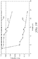
- n eff 2 fn v 2 + 1 ⁇ f n b 2
- the effective index of the gradient optical film is the volume weighted average of the indices of refraction of the voids and the binder.
- a gradient optical film that has a void volume fraction of about 50% and a binder that has an index of refraction of about 1.5 has an effective index of about 1.25.
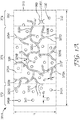
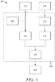
- FIG. 1A is a schematic side-view of a gradient optical film 300A that includes a network of voids or plurality of interconnected voids 320 and a plurality of particles 340 dispersed within a binder 310.
- Gradient optical film 300A has a porous interior by virtue of the presence of network of voids 320 within the gradient optical film.
- the gradient optical film can include one or more networks of interconnected pores or voids.
- network of voids 320 can be regarded to include interconnected voids or pores 320A-320C.
- a local morphology for example a first local volume fraction of interconnected voids 370A and a second volume fraction of interconnected voids 375A, can vary along a thickness t 1 direction (also referred to as the "z" direction) within gradient optical film 300A.
- first local volume fraction of interconnected voids 370A has been depicted as being greater than second volume fraction of interconnected voids 375A.
- the local volume fraction of interconnected voids, and pore-size distribution can vary along the thickness direction in several ways, for example, as described in "Process for Gradient Nanovoided Article" ( U.S. Serial No. 61/254674 ); and “Gradient Low Index Article and Method” ( U.S. Serial No. 61/254673 .
- a local volume fraction of interconnected voids for example a third local volume fraction of interconnected voids 372, a fourth local volume fraction of interconnected voids 374, and a fifth local volume fraction of interconnected voids 376, can vary along the direction of a transverse plane "L" (that is, generally along the "x" and/or "y" direction) within gradient optical film 300A.
- L transverse plane
- fifth local volume fraction of interconnected voids 376 has been depicted as being greater than either the third local volume fraction of interconnected voids 372 or the fourth local volume fraction of interconnected voids 374.
- the local volume fraction of interconnected voids, and void size distribution can also vary along the thickness direction in several ways, as described elsewhere.
- the gradient optical film is a porous film meaning that the network of voids 320 forms one or more passages between first and second major surfaces 330 and 332, respectively.
- the local volume fraction of interconnected voids can vary along any combination of the "x", "y", and "z" directions.
- the network of voids can be regarded to include a plurality of interconnected voids. Some of the voids can be at a surface of the gradient optical film and can be regarded to be surface voids.
- voids 320D and 320E are at a second major surface 332 of the gradient optical film and can be regarded as surface voids 320D and 320E
- voids 320F and 320G are at a first major surface 330 of the gradient optical film and can be regarded as surface voids 320F and 320G.
- voids 320B and 320C are within the interior of the gradient optical film and away from the exterior surfaces of the gradient optical film and can be regarded as interior voids 320B and 320C, even though an interior void can be connected to a major surface via, for example, other voids.
- Voids 320 have a size d 1 that can generally be controlled by choosing suitable composition and fabrication techniques, such as the various coating, drying and curing conditions.
- d 1 can be any desired value in any desired range of values.
- At least a majority of the voids such as at least 60% or 70% or 80% or 90% or 95% of the voids, have a size that is not greater than about 10 microns, or not greater than about 7 microns, or not greater than about 5 microns, or not greater than about 4 microns, or not greater than about 3 microns, or not greater than about 2 microns, or not greater than about 1 micron, or not greater than about 0.7 microns, or not greater than about 0.5 microns.
- plurality of interconnected voids 320 has an average void or pore size that is not greater than about 5 microns, or not greater than about 4 microns, or not greater than about 3 microns, or not greater than about 2 microns, or not greater than about 1 micron, or not greater than about 0.7 microns, or not greater than about 0.5 microns.
- some of the voids can be sufficiently small so that their primary optical effect is to reduce the effective index, while some other voids can reduce the effective index and scatter light, while still some other voids can be sufficiently large so that their primary optical effect is to scatter light.
- Particles 340 have a size d 2 that can be any desired value in any desired range of values. For example, in some cases at least a majority of the particles, such as at least 60% or 70% or 80% or 90% or 95% of the particles, have a size that is in a desired range.
- At least a majority of the particles such as at least 60% or 70% or 80% or 90% or 95% of the particles, have a size that is not greater than about 5 microns, or not greater than about 3 microns, or not greater than about 2 microns, or not greater than about 1 micron, or not greater than about 700 nm, or not greater than about 500 nm, or not greater than about 200 nm, or not greater than about 100 nm, or not greater than about 50 nm, or even not greater than about 20 nm.
- plurality of particles 340 has an average particle size that is not greater than about 5 microns, or not greater than about 3 microns, or not greater than about 2 microns, or not greater than about 1 micron, or not greater than about 700 nm, or not greater than about 500 nm, or not greater than about 200 nm, or not greater than about 100 nm, or not greater than about 50 nm.
- some of the particles can be sufficiently small so that they primarily affect the effective index, while some other particles can affect the effective index and scatter light, while still some other particles can be sufficiently large so that their primary optical effect is to scatter light.
- d 1 and/or d 2 are sufficiently small so that the primary optical effect of the voids and the particles is to affect the effective index of gradient optical film 300A.
- d 1 and/or d 2 are not greater than about ⁇ /5, or not greater than about ⁇ /6, or not greater than about ⁇ /8, or not greater than about ⁇ /10, or not greater than about ⁇ /20, where ⁇ is the wavelength of light.
- d 1 and d 2 are not greater than about 70 nm, or not greater than about 60 nm, or not greater than about 50 nm, or not greater than about 40 nm, or not greater than about 30 nm, or not greater than about 20 nm, or not greater than about 10 nm.
- the voids and the particles may also scatter light, but the primary optical effect of the voids and the particles is to define an effective medium in the gradient optical film that has an effective index.
- the effective index depends, in part, on the indices of refraction of the voids, the binder, and the particles. In some cases, the effective index is a reduced effective index, meaning that the effective index is less than the index of the binder and the index of the particles.
- d 1 and d 2 are sufficiently small so that a substantial fraction, such as at least about 60%, or at least about 70%, or at least about 80%, or at least about 90%, or at least about 95% of voids 320 and particles 340 have the primary optical effect of reducing the effective index.
- a substantial fraction such as at least about 60%, or at least about 70%, or at least about 80%, or at least about 90%, or at least about 95% the voids and/or the particles, have a size that is in a range from about 1 nm to about 200 nm, or from about 1 nm to about 150 nm, or from about 1 nm to about 100 nm, or from about 1 nm to about 50 nm, or from about 1 nm to about 20 nm.
- the index of refraction n 1 of particles 340 can be sufficiently close to the index n b of binder 310, so that the effective index does not depend, or depends very little, on the index of refraction of the particles.
- the difference between n 1 and n b is not greater than about 0.01, or not greater than about 0.007, or not greater than about 0.005, or not greater than about 0.003, or not greater than about 0.002, or not greater than about 0.001.
- particles 340 are sufficiently small and their index is sufficiently close to the index of the binder, that the particles do not primarily scatter light or affect the index.
- the primary effect of the particles can, for example, be to enhance the strength of gradient optical film 300A.
- particles 340 can enhance the process of making the gradient optical film, although gradient optical film 300A can be made with no particles.
- the optical haze of gradient optical film 300A that is due to voids 320 and particles 340 is not greater than about 5%, or not greater than about 4%, or not greater than about 3.5%, or not greater than about 4%, or not greater than about 3%, or not greater than about 2.5%, or not greater than about 2%, or not greater than about 1.5%, or not greater than about 1%.
- the effective index of the effective medium of the gradient optical film is not greater than about 1.35, or not greater than about 1.3, or not greater than about 1.25, or not greater than about 1.2, or not greater than about 1.15, or not greater than about 1.1, or not greater than about 1.05.
- the thickness of the gradient optical film is, not less than about 2000 nm.
- d 1 and/or d 2 are sufficiently large so that their primary optical effect is to scatter light and produce optical haze.
- d 1 and/or d 2 are not less than about 200 nm, or not less than about 300 nm, or not less than about 400 nm, or not less than about 500 nm, or not less than about 600 nm, or not less than about 700 nm, or not less than about 800 nm, or not less than about 900 nm, or not less than about 1000 nm.
- the voids and the particles may also affect the index, but often, their primarily optical effect is to scatter light. In such cases, light incident on the gradient optical film can be scattered by both the voids and the particles.
- Gradient optical film 300A can be used in many optical applications.
- the gradient optical film can be used to support or promote total internal reflection (TIR) or enhance internal reflection meaning that the reflection is greater than what a material with index n b would produce.
- gradient optical film 300A is sufficiently thick so that the evanescent tail of a light ray that undergoes total internal reflection at a surface of the gradient optical film, does not optically couple, or optically couples very little, or even is controllably coupled, across the thickness of the gradient optical film.
- the thickness t 1 of gradient optical film 300A is not less than about 1 micron, or not less than about 1.1 micron, or not less than about 1.2 microns, or not less than about 1.3 microns, or not less than about 1.4 microns, or not less than about 1.5 microns, or not less than about 1.7 microns, or not less than about 2 microns.
- a sufficiently thick gradient optical film 300A can prevent or reduce an undesired optical coupling of the evanescent tail of an optical mode across the thickness of the gradient optical film.
- the TIR properties of the gradient optical film can vary in different regions of the film, along the transverse plane, as described elsewhere.
- portions of the gradient optical film 300A have a low optical haze.
- the optical haze of the gradient optical film is not greater than about 5%, or not greater than about 4%, or not greater than about 3.5%, or not greater than about 4%, or not greater than about 3%, or not greater than about 2.5%, or not greater than about 2%, or not greater than about 1.5%, or not greater than about 1%.
- the gradient optical film can have a reduced effective index that is not greater than about 1.35, or not greater than about 1.3, or not greater than about 1.2, or not greater than about 1.15, or not greater than about 1.1, or not greater than about 1.05.
- optical haze is defined as the ratio of the transmitted light that deviates from the normal direction by more than 4 degrees to the total transmitted light. Haze values disclosed herein were measured using a Haze-Gard Plus haze meter (BYK-Gardner, Silver Springs, Md.) according to the procedure described in ASTM D1003. The haze properties of the gradient optical film can vary in different regions of the film, along the transverse plane, as described elsewhere.
- portions of the gradient optical film 300A have a high optical haze.
- the haze of the gradient optical film is not less than about 40%, or not less than about 50%, or not less than about 60%, or not less than about 70%, or not less than about 80%, or not less than about 90%, or not less than about 95%.
- gradient optical film 300A can have an intermediate optical haze, for example, between about 5% and about 50% optical haze.
- portions of the gradient optical film 300A have a high diffuse optical reflectance.
- the diffuse optical reflectance of the gradient optical film is not less than about 30%, or not less than about 40%, or not less than about 50%, or not less than about 60%.
- the diffuse optical reflectance of the gradient optical film can vary in different regions of the film, along the transverse plane, as described elsewhere.
- portions of the gradient optical film 300A have a high optical clarity.
- optical clarity refers to the ratio (T 2 -T 1 )/(T 1 +T 2 ), where T 1 is the transmitted light that deviates from the normal direction between 1.6 and 2 degrees, and T 2 is the transmitted light that lies between zero and 0.7 degrees from the normal direction. Clarity values disclosed herein were measured using a Haze-Gard Plus haze meter from BYK-Gardner.
- the clarity is not less than about 40%, or not less than about 50%, or not less than about 60%, or not less than about 70%, or not less than about 80%, or not less than about 90%, or not less than about 95%.
- the optical clarity of the gradient optical film can vary in different regions of the film, along the transverse plane, as described elsewhere.
- portions of the gradient optical film 300A have a low optical clarity.
- the optical clarity of the gradient optical film is not greater than about 40%, or not greater than about 20%, or not greater than about 10%, or not greater than about 7%, or not greater than about 5%, or not greater than about 4%, or not greater than about 3%, or not greater than about 2%, or not greater than about 1%.
- gradient optical film can have any porosity, pore-size distribution, or void volume fraction that may be desirable in an application.
- the volume fraction of plurality of voids 320 in gradient optical film 300A is not less than about 20%, or not less than about 30%, or not less than about 40%, or not less than about 50%, or not less than about 60%, or not less than about 70%, or not less than about 80%, or not less than about 90%.
- portions of the gradient optical film can manifest some low-index properties, even if the gradient optical film has a high optical haze and/or diffuse reflectance.
- the portions of the gradient optical film can support TIR at angles that correspond to an index that is smaller than the index n b of binder 310.
- particles 340 such as particles 340A and 340B, are solid particles.
- gradient optical film 300A may additionally or alternatively include a plurality of hollow or porous particles 350.
- Particles 340 can be any type particles that may be desirable in an application.
- particles 340 can be organic or inorganic particles.
- particles 340 can be silica, zirconium oxide or alumina particles.
- Particles 340 can have any shape that may be desirable or available in an application.
- particles 340 can have a regular or irregular shape.
- particles 340 can be approximately spherical.
- the particles can be elongated.
- gradient optical film 300A includes a plurality of elongated particles 340.
- the elongated particles have an average aspect ratio that is not less than about 1.5, or not less than about 2, or not less than about 2.5, or not less than about 3, or not less than about 3.5, or not less than about 4, or not less than about 4.5, or not less than about 5.
- the particles can be in the form or shape of a string-of-pearls (such as Snowtex-PS particles available from Nissan Chemical, Houston, TX) or aggregated chains of spherical or amorphous particles, such as fumed silica.
- a string-of-pearls such as Snowtex-PS particles available from Nissan Chemical, Houston, TX
- aggregated chains of spherical or amorphous particles such as fumed silica.
- Particles 340 may or may not be functionalized. In some cases, particles 340 are not functionalized. In some cases, particles 340 are functionalized so that they can be dispersed in a desired solvent or binder 310 with no, or very little, clumping. In some cases, particles 340 can be further functionalized to chemically bond to binder 310. For example, particles 340, such as particle 340A, can be surface modified and have reactive functionalities or groups 360 to chemically bond to binder 310. In such cases, at least a significant fraction of particles 340 is chemically bound to the binder. In some cases, particles 340 do not have reactive functionalities to chemically bond to binder 310. In such cases, particles 340 can be physically bound to binder 310, or binder 310 can encapsulate particles 340.
- some of the particles have reactive groups and others do not have reactive groups. For example in some cases, about 10% of the particles have reactive groups and about 90% of the particles do not have reactive groups, or about 15% of the particles have reactive groups and about 85% of the particles do not have reactive groups, or about 20% of the particles have reactive groups and about 80% of the particles do not have reactive groups, or about 25% of the particles have reactive groups and about 75% of the particles do not have reactive groups, or about 30% of the particles have reactive groups and about 60% of the particles do not have reactive groups, or about 35% of the particles have reactive groups and about 65% of the particles do not have reactive groups, or about 40% of the particles have reactive groups and about 60% of the particles do not have reactive groups, or about 45% of the particles have reactive groups and about 55% of the particles do not have reactive groups, or about 50% of the particles have reactive groups and about 50% of the particles do not have reactive groups. In some cases, some of the particles may be functionalized with both reactive and unreactive groups on the same particle.
- the ensemble of particles may include a mixture of sizes, reactive and nonreactive particles and different types of particles, for example, organic particles including polymeric particles such as acrylics, polycarbonates, polystyrenes, silicones and the like; or inorganic particles such as glasses or ceramics including, for example, silica and zirconium oxide, and the like.
- organic particles including polymeric particles such as acrylics, polycarbonates, polystyrenes, silicones and the like
- inorganic particles such as glasses or ceramics including, for example, silica and zirconium oxide, and the like.
- Binder 310 can be or include any material that may be desirable in an application.
- binder 310 can be a curable material that forms a polymer, such as a crosslinked polymer.
- binder 310 is a polymerizable material, such as a polymerizable material that is radiation-curable, such as a UV curable material.
- Gradient optical film 300A can be produced using any method that may be desirable in an application.
- gradient optical film 300A can be produced by the processes described in co-pending application titled “PROCESS AND APPARATUS FOR A NANOVOIDED ARTICLE", U.S. Serial No. 61/169429 , co-pending application titled “PROCESS AND APPARATUS FOR COATING WITH REDUCED DEFECTS”, U.S. Serial No. 61/169427 , and co-pending application titled “PROCESS FOR GRADIENT NANOVOIDED ARTICLE", U.S. Serial No. 61/254674 .
- a solution is prepared that includes a plurality of particles, such as nano-particles, and a polymerizable material dissolved in a solvent, where the polymerizable material can include, for example, one or more types of monomers.
- the polymerizable material is polymerized, for example by applying heat or light, to form an insoluble polymer matrix in the solvent.
- the solvent solubility in the cured matrix
- the solvent is subsequently removed leaving pores and voids which yield the porous coating.
- phase separation is a primary factor in determining the morphology and topography of the film.
- the final structure is also dependent on the mechanical properties of the matrix network.
- the network modulus and strength should be sufficient to maintain a void space as the solvent is removed.
- the composition and extent of cure are factors in determining the morphology.
- the morphology can be controlled.
- the process may also utilize a controlled environment region between the coating station and polymerization apparatus, as described elsewhere. This region enables improved control of the coated film composition and environment.
- the polymerization apparatus can be located anywhere between the coating station and dryer. Controlling the environment during polymerization is also advantageous.
- the polymerized coating is subsequently dried and may be further post-processed with, for example, conventional UV radiation systems to further cure the material. Radiation sources that could be used in the polymerization apparatus include LEDs, UV lasers, UV lamps, and e-beam).
- the solvent may still include some of the polymerizable material, although at a lower concentration.
- the solvent is removed by drying or evaporating the solution resulting in gradient optical film 300A that includes a network, or a plurality, of voids 320 dispersed in polymer binder 310.
- the gradient optical film further includes plurality of particles 340 dispersed in the polymer. The particles are bound to the binder, where the bonding can be physical or chemical, or be encapsulated by the binder.
- Gradient optical film 300A can have other materials in addition to binder 310 and particles 340.
- gradient optical film 300A can include one or more additives, such as for example, coupling agents, to help wet the surface of a substrate, not expressly shown in FIG. 1 , on which the gradient optical film is formed.
- gradient optical film 300A can include one or more colorants, such a carbon black, for imparting a color, such as the black color, to the gradient optical film.
- Other exemplary materials in gradient optical film 300A include initiators, such as one or more photoinitiators; anti-stats; adhesion promoters; surfactants; UV absorbers; release agents; or others, as described elsewhere.
- gradient optical film 300A can include a down converting material that is capable of absorbing light and reemitting a longer wavelength light. Exemplary down converting materials include phosphors.
- gradient optical film 300A can have a range of desirable porosities for any weight ratio of binder 310 to plurality of particles 340.
- the weight ratio can be any value that may be desirable in an application.
- the weight ratio of binder 310 to plurality of particles 340 is not less than about 1:2.5, or not less than about 1:2.3, or not less than about 1:2, or not less than about 1:1, or not less than about 1.5:1, or not less than about 2:1, or not less than about 2.5:1, or not less than about 3:1, or not less than about 3.5:1, or not less than about 4:1, or not less than about 5:1.
- the weight ratio is in a range from about 1:2.3 to about 4:1.
- top major surface 332 of gradient optical film 300A can be treated to, for example, improve the adhesion of the gradient optical film to another layer.
- the top surface can be corona treated.
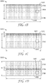
- FIGS. 1B-1I are schematic top views of a gradient optical film 300B-300I, respectively, according to different aspects of the disclosure.
- the numbered elements 310-360 and the sizes d 1 - d 3 described for FIG. 1A are not shown in FIGS. 1B-1I ; however, each of the descriptions provided for gradient optical film 300A of FIG. 1A also correspond to the gradient optical film 300B-300I of FIGS. 1B-1I , respectively.
- any of the techniques for creating a gradient optical film that varies with thickness can also be used in conjunction with the gradient optical films that vary across the transverse plane (parallel to the surface of a film) as shown in FIGS. 1A-1I . Techniques for variation in thickness gradients are described, for example, in co-pending application titled "PROCESS FOR GRADIENT NANOVOIDED ARTICLE", U.S. Serial No. 61/254674 .
- gradient optical films having transverse plane variations can be generated, for example, by using a difference in the polymerization initiator concentration or a difference in the polymerization inhibitor concentration proximate adjacent regions.
- a shadow mask can be positioned between the lamps and the coating, such that the intensity of polymerization light decreases proximate adjacent regions.
- the intensity of radiation can be temporally or spatially varied across the width of the coating, affecting the local morphology, as described elsewhere.
- a multilayer coating technique can be used, for example, where the regions include different ratios of polymeric binder to particles.
- Techniques that modify dose include, for example, light source techniques including temporal modification (pulse the LEDs), LED laser writing, control of different wavelength light sources, and video image (moves with the web); mask techniques including shadow masks, grayscale masks, printed masks, and masks interior to a transparent roll with light source inside; and machine techniques including web speed variation, variation of distance or focus of light.
- Solvent modification techniques include, for example, temperature gradients; differential drying techniques including vacuum, flow, masked drying, and saturation of gas; and solvent coating techniques including coating in stripes of other patterns.
- Chemical techniques include, for example, patterned photoinitiator and patterned photoinhibitor including chemical additives, gasses, and oxygen inhibition.
- Coating techniques include, for example, stripe coating and pattern overcoating.
- External techniques include, for example, applied fields such as, for example, electric or magnetic or the like.
- any desired pattern can be generated by combinations of the described techniques, including, for example, indicia such as letters, words, symbols, or even pictures.
- the patterns can also be continuous, discontinuous, monotonic, serpentine, any smoothly varying function; stripes; varying in the machine direction, the transverse direction, or both; gradients can form an image, logo, or text; and they can include patterned coatings and/or perforations.
- gradient optical film 300B includes a length L and a width W that defines a transverse plane LW.
- Gradient optical film 300B further includes a local morphology 390B that varies along the transverse plane LW, for example, in a monotonic manner as shown.
- a first local volume fraction of interconnected voids 370B proximate a first edge 330B of gradient optical film 300B is lower than a second local volume fraction of interconnected voids 375B proximate a second edge 332B of gradient optical film 300B, and varies monotonically between the edges.
- Gradient optical film 300B can be prepared using a variety of techniques, as described elsewhere.
- gradient optical film 300C includes a length L and a width W that defines a transverse plane LW.
- Gradient optical film 300C further includes a local morphology 390C that varies along the transverse plane LW, for example, in a step-wise manner as shown.
- a first local volume fraction of interconnected voids 370C proximate a first edge 330C of gradient optical film 300C is lower than a second local volume fraction of interconnected voids 375C proximate a second edge 332C of gradient optical film 300C.
- first local volume fraction of interconnected voids 370C transitions sharply (that is, step-wise) to second local volume fraction of interconnected voids 375C.
- a line width d1 of the second volume fraction of interconnected voids 375C can be a small percentage of the width W, for example, from about 1% to about 5%, or to about 10%, or to about 20%, or to about 30% or more of the total width W. Any number of regions having the first local volume fraction of interconnected voids 370C can be formed across the width W of the gradient optical film 300C, as apparent to those of skill in the art.
- Gradient optical film 300C can be prepared using a variety of techniques, as described elsewhere.
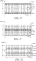
- gradient optical film 300D includes a length L and a width W that defines a transverse plane LW.
- Gradient optical film 300D further includes a local morphology 390D that varies along the transverse plane LW, for example, having a minimum local volume fraction of interconnected voids 377D as shown.
- a first local volume fraction of interconnected voids 370D proximate a first edge 330D of gradient optical film 300D is approximately the same as a second local volume fraction of interconnected voids 375D proximate a second edge 332D of gradient optical film 300D.
- FIG. 1 shows a first local volume fraction of interconnected voids 370D proximate a first edge 330D of gradient optical film 300D.
- first local volume fraction of interconnected voids 370D transitions sharply (that is, step-wise) to minimum local volume fraction of interconnected voids 377D.
- the transition can be abrupt, as in a step-change, or the transition can be smoothed slightly, for example, an "S" shaped transition (not shown).
- a line width d1 of the minimum volume fraction of interconnected voids 377D can be a small percentage of the width W, for example, from about 1% to about 5%, or to about 10%, or to about 20%, or to about 30% or more of the width W.
- the relative position of the minimum local volume fraction of interconnected voids 377D can be located anywhere, and in multiple positions across the width W.
- Gradient optical film 300D can be prepared using a variety of techniques, as described elsewhere.
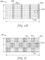
- gradient optical film includes a length L and a width W that defines a transverse plane LW.
- Gradient optical film 300E further includes a local morphology 390E that varies along the transverse plane LW, for example, having a step-change local volume fraction of interconnected voids proximate a first and a second edge 330E, 332E, as shown.
- a first local volume fraction of interconnected voids 370E proximate a first edge 330E of gradient optical film 300E is approximately the same as a second local volume fraction of interconnected voids 375E proximate a second edge 332E of gradient optical film 300E.
- FIG. 1E shown FIG.
- first local volume fraction of interconnected voids 370E transitions sharply (that is, step-wise) to maximum local volume fraction of interconnected voids 377E.
- each of the first and second local volume fraction of interconnected voids 370E and 375E can have transitions that are not step-wise (not shown, but similar to the monotonic variation shown in FIG. 1B ).
- Gradient optical film 300E can be prepared using a variety of techniques, as described elsewhere.
- gradient optical film 300F includes a length L and a width W that defines a transverse plane LW.
- Gradient optical film 300F further includes a local morphology 390F that varies along the transverse plane LW, for example, having a gradient minimum local volume fraction of interconnected voids 377F as shown.
- a first local volume fraction of interconnected voids 370F proximate a first edge 330F of gradient optical film 300F is approximately the same as a second local volume fraction of interconnected voids 375F proximate a second edge 332F of gradient optical film 300F.
- FIG. IF shown FIG.
- first local volume fraction of interconnected voids 370F transitions gradually (that is, in a monotonic gradient) to a minimum local volume fraction of interconnected voids 377F, and again transitions gradually to the second volume fraction of interconnected voids 375F.
- Gradient optical film 300F can be prepared using a variety of techniques, as described elsewhere.
- gradient optical film 300G includes a length L and a width W that defines a transverse plane LW.
- Gradient optical film 300G further includes a local morphology 390G that varies along the transverse plane LW, for example, having a pair of step-change local volume fraction of interconnected voids 377G, 378G, as shown.
- a first local volume fraction of interconnected voids 370G proximate a first edge 330G of gradient optical film 300G is approximately the same as a second local volume fraction of interconnected voids 375G proximate a second edge 332G of gradient optical film 300G.
- FIG. 1G shows that shows that the first local volume fraction of interconnected voids 370G proximate a first edge 330G of gradient optical film 300G.
- first local volume fraction of interconnected voids 370G transitions sharply (that is, step-wise) to minimum local volume fraction of interconnected voids 377G, transitions sharply again to a maximum local volume fraction of interconnected voids 380G, transitions sharply again to a minimum local volume fraction of interconnected voids 378G, and finally transitions sharply yet again to the second local volume fraction of interconnected voids 375G.
- each of the local volume fraction of interconnected voids can have transitions that are not step-wise (not shown, but similar to the monotonic variation shown in FIG. 1B ).
- Gradient optical film 300G can be prepared using a variety of techniques, as described elsewhere.
- gradient optical film 300H includes a length L and a width W that defines a transverse plane LW.
- Gradient optical film 300H further includes a local morphology 390H that varies along the transverse plane LW, for example, having a step-change local volume fraction of interconnected voids 380H, 382H that change along the length L of the gradient optical film 300H, as shown.
- first local volume fraction of interconnected voids 380H is perpendicular to both a first edge 330H and a second edge 332H of gradient optical film 300H
- a second local volume fraction of interconnected voids 382H is also perpendicular to the first and second edges 330H, 332H of gradient optical film 300 H.
- first local volume fraction of interconnected voids 380H transitions sharply (that is, step-wise) to minimum local volume fraction of interconnected voids 382H, and continues in a like fashion down the length L of the gradient optical film.
- each of the local volume fraction of interconnected voids can have transitions that are not step-wise (not shown, but similar to the monotonic variation shown in FIG. 1B ).
- Gradient optical film 300H can be prepared using a variety of techniques, as described elsewhere.
- gradient optical film 300I includes a length L and a width W that defines a transverse plane LW.
- Gradient optical film 3001 further includes a local morphology 3901 that varies along the transverse plane LW, for example, having a step-change local volume fraction of interconnected voids 3801, 3821 that change in a checkerboard fashion, as shown. It is to be understood that any desired pattern can be formed across the transverse plane, including, for example, geometric shapes, words, indicia, images, and the like. In one particular embodiment, for example shown FIG.
- first local volume fraction of interconnected voids 3801 transitions sharply (that is, step-wise) to minimum local volume fraction of interconnected voids 3821, and continues in a like fashion across the transverse plane LW of the gradient optical film.
- each of the local volume fraction of interconnected voids can have transitions that are not step-wise (not shown, but similar to the monotonic variation shown in FIG. 1B ).
- Gradient optical film 3001 can be prepared using a variety of techniques, as described elsewhere.
- FIG. 2 is a schematic side-view of an optical construction 600 that includes a gradient optical film 630 disposed on a substrate 610.
- substrate 610 is a release liner that provides a transferable gradient optical film 630, meaning that, for example, the exposed top major surface 632 of the gradient optical film 630 may be placed in contact with a substrate or surface and the release liner may thereafter be stripped away from the gradient optical film to expose a bottom major surface 634 of the gradient optical film that can, for example, be bonded to another substrate or surface.
- the release force for releasing low index layer 630 from a release liner 610 is generally less than about 200 g-force/inch, or less than about 150 g-force/inch, or less than about 100 g-force/inch, or less than about 75 g-force/inch, or less than about 50 g-force/inch.
- Gradient optical film 630 can be similar to any gradient optical film disclosed herein.
- gradient optical film 630 can be similar to one of gradient optical films 300A-300I.
- gradient optical film 630 can include multiple layers, where one or more layers is similar to one of gradient optical films 300A-300I, one or more layers includes a "z" gradient film as described elsewhere, or one or more layers includes a non-gradient film, or a combination of gradient films and non-gradient films.
- one of gradient optical films 300A-300I may be coated directly onto substrate 610.
- one of gradient optical films 300A-300I may be first formed and thereafter transferred onto substrate 610.
- Substrate 610 can be translucent, transparent, or opaque.
- Substrate 610 can be or include any material that may be suitable in an application, such as a dielectric, a semiconductor, or a conductor (such as a metal).
- substrate 610 can include or be made of glass and polymers such as polyethylene terapthalate (PET), polycarbonates, and acrylics.
- PET polyethylene terapthalate
- the substrate 610 can include a polarizer such as a reflective polarizer, an absorbing polarizer, a wire-grid polarizer, or a fiber polarizer.
- the substrate 610 can include multiple layers, such as a multilayer optical film including, for example, multilayer reflecting films and multilayer polarizing films.
- the substrate 610 can include a structured surface, such as a surface having a plurality of microstructures including, for example, vee-grooves such as a Brightness Enhancing Film (BEF), cube-corners, such as a retroreflector, or other microstructures as known in the art.
- the substrate 610 can include further coatings on a major surface such as, for example, a primer coating or an adhesive coating.
- a fiber polarizer includes a plurality of substantially parallel fibers that form one or more layers of fibers embedded within a binder with at least one of the binder and the fibers including a birefringent material.
- the substantially parallel fibers define a transmission axis and a reflection axis.
- the fiber polarizer substantially transmits incident light that is polarized parallel to the transmission axis and substantially reflects incident light that is polarized parallel to the reflection axis. Examples of fiber polarizers are described in, for example, U.S. Patent Nos. 7,599,592 and 7,526,164 .
- the substrate 610 can include a partial reflector.
- a partial reflector is an optical element or a collection of optical elements which reflect at least 30% of incident light while transmitting the remainder, minus absorption losses.
- Suitable partial reflectors include, for example, foams, polarizing and non-polarizing multilayer optical films, microreplictated structures (for example BEF), polarized and non-polarized blends, wire grid polarizers, partially transmissive metals such as silver or nickel, metal/dielectric stacks such as silver and indium tin oxide, and asymmetric optical films.
- Asymmetric optical films are described, for example, in U.S. Patent No. 6, 924,014 (Ouderkirk et al. ) and also in PCT Publication WO2008/144636 .
- Also useful as partial reflectors are perforated partial reflectors or mirrors, such as, for example, perforating ESR (available from 3M Company).
- substrate 610 can be a reflective polarizer.
- a reflective polarizer layer substantially reflects light that has a first polarization state and substantially transmits light that has a second polarization state, where the two polarization states are mutually orthogonal.
- the average reflectance of a reflective polarizer in the visible for the polarization state that is substantially reflected by the reflective polarizer is at least about 50%, or at least about 60%, or at least about 70%, or at least about 80%, or at least about 90%, or at least about 95%.
- the average transmittance of a reflective polarizer in the visible for the polarization state that is substantially transmitted by the reflective polarizer is at least about 50%, or at least about 60%, or at least about 70%, or at least about 80%, or at least about 90%, or at least about 95%, or at least about 97%, or at least about 98%, or at least about 99%.
- the reflective polarizer substantially reflects light having a first linear polarization state (for example, along the x-direction) and substantially transmits light having a second linear polarization state (for example, along the z-direction).
- any suitable type of reflective polarizer may be used such as, for example, a multilayer optical film (MOF) reflective polarizer such as VikuitiTM Dual Brightness Enhancement Film (DBEF), a diffusely reflective polarizing film (DRPF) having a continuous phase and a disperse phase, such as a VikuitiTM Diffuse Reflective Polarizer Film (“DRPF”) available from 3M Company, St. Paul, Minnesota, a wire grid reflective polarizer described in, for example, U.S. Patent No. 6,719,426 , or a cholesteric reflective polarizer.
- MOF multilayer optical film
- DBEF VikuitiTM Dual Brightness Enhancement Film
- DRPF diffusely reflective polarizing film having a continuous phase and a disperse phase
- DRPF VikuitiTM Diffuse Reflective Polarizer Film
- wire grid reflective polarizer described in, for example, U.S. Patent No. 6,719,426
- cholesteric reflective polarizer choleste
- the reflective polarizer layer can be or include an MOF reflective polarizer, formed of alternating layers of different polymer materials, where one of the sets of alternating layers is formed of a birefringent material, where the refractive indices of the different materials are matched for light polarized in one linear polarization state and unmatched for light in the orthogonal linear polarization state.
- an incident light in the matched polarization state is substantially transmitted through the reflective polarizer and an incident light in the unmatched polarization state is substantially reflected by reflective polarizer.
- an MOF reflective polarizer can include a stack of inorganic dielectric layers.
- the reflective polarizer can be or include a partially reflecting layer that has an intermediate on-axis average reflectance in the pass state.
- the partially reflecting layer can have an on-axis average reflectance of at least about 90% for visible light polarized in a first plane, such as the xy-plane, and an on-axis average reflectance in a range from about 25% to about 90% for visible light polarized in a second plane, such as the xz-plane, perpendicular to the first plane.
- Such partially reflecting layers are described in, for example, U.S. Patent Publication No. 2008/064133 .
- the reflective polarizer can be or include a circular reflective polarizer, where light circularly polarized in one sense, which may be the clockwise or counterclockwise sense (also referred to as right or left circular polarization), is preferentially transmitted and light polarized in the opposite sense is preferentially reflected.
- a circular polarizer includes a cholesteric liquid crystal polarizer.
- the reflective polarizer can be a multilayer optical film that reflects or transmits light by optical interference, such as those described in Provisional U.S. Patent Application No. 61/116132, filed November 19, 2008 ; Provisional U.S. Patent Application No. 61/116291, filed November 19, 2008 ; Provisional U.S. Patent Application No. 61/116294 , filed November 19, 2008 ; Provisional U.S. Patent Application No. 61/116295, filed November 19, 2008 ; Provisional U.S. Patent Application No. 61/116295, filed November 19, 2008 ; and International Patent Application No. PCT/US 2008/060311, filed May 19, 2008 , claiming priority from Provisional U.S. Patent Application No. 60/939085, filed May 20, 2007 .
- substrate 610 can be a microstructured surface, such as a prismatic light directing film.
- gradient optical film 630 can be coated on the prism side of a light redirecting film such as VikuitiTM Brightness Enhancing Film (BEF), available from 3M Company.
- BEF VikuitiTM Brightness Enhancing Film
- the BEF includes a plurality of linear prisms with, for example, a 24 micron pitch and a prism peak or apex angle of about 90 degrees.
- the gradient optical film 630 can be coated on the microstructured surface as a conformal coating, a planarized coating, or pattern coated, as known to those of skill in the art.
- Substantial portions of each two neighboring major surfaces in optical construction 600 are in physical contact with each other along the bottom major surface 634 of gradient optical film 630.
- at least 50%, or at least 60%, or at least 70%, or at least 80%, or at least 90%, or at least 95% of the two neighboring major surfaces are in physical contact with each other.
- gradient optical film 630 is coated directly on substrate 610.
- FIG. 3 is a schematic side-view of an optical construction 700 that includes a gradient optical film 730 disposed on a substrate 710, and an optical adhesive layer 720 disposed on gradient optical film 730.
- Substrate 710 can be any of the substrates described elsewhere, including, for example, a substrate such as substrate 610 described with reference to FIG. 2 .
- the optical adhesive layer 720 can act as a sealer to inhibit infiltration of voids of gradient optical film 730.
- Optical adhesive layer 720 can be any optical adhesive that may be desirable and/or available in an application.
- Optical adhesive layer 720 is of sufficient optical quality and light stability such that, for example, the adhesive layer does not yellow with time or upon exposure to weather so as to degrade the optical performance of the adhesive and the gradient optical film.
- optical adhesive layer 720 can be a substantially clear optical adhesive meaning that the adhesive layer has a high specular transmittance and a low diffuse transmittance.
- the specular transmittance of optical adhesive layer 720 is not less than about 70%, or not less than about 80%, or not less than about 90%, or not less than about 95%.
- optical adhesive layer 720 is substantially optically diffusive, meaning that the adhesive layer has a high diffuse transmittance and a low specular transmittance, and the optical adhesive layer 720 can have a white appearance.
- the optical haze of an optically diffusive adhesive layer 720 is not less than about 30%, or not less than about 30%, or not less than about 50%, or not less than about 60%, or not less than about 70%, or not less than about 80%, or not less than about 90%, or not less than about 95%.
- the diffuse reflectance of the diffusive adhesive layer is not less than about 20%, or not less than about 30%, or not less than about 40%, or not less than about 50%, or not less than about 60%.
- the adhesive layer can be optically diffusive by including a plurality of particles dispersed in an optical adhesive where the particles and the optical adhesive have different indices of refraction.
- the mismatch between the two indices of refraction can result in light scattering.
- Exemplary optical adhesives include pressure sensitive adhesives (PSAs), heat-sensitive adhesives, solvent-volatile adhesives, repositionable adhesives or reworkable adhesives, and UV-curable adhesives such as UV-curable optical adhesives available from Norland Products, Inc.
- PSAs pressure sensitive adhesives
- heat-sensitive adhesives solvent-volatile adhesives
- solvent-volatile adhesives solvent-volatile adhesives
- repositionable adhesives or reworkable adhesives repositionable adhesives or reworkable adhesives
- UV-curable adhesives such as UV-curable optical adhesives available from Norland Products, Inc.
- Exemplary PSAs include those based on natural rubbers, synthetic rubbers, styrene block copolymers, (meth)acrylic block copolymers, polyvinyl ethers, polyolefins, and poly(meth)acrylates.
- (meth)acrylic (or acrylate) refers to both acrylic and methacrylic species.
- Other exemplary PSAs include (meth)acrylates, rubbers, thermoplastic elastomers, silicones, urethanes, and combinations thereof. In some cases, the PSA is based on a (meth)acrylic PSA or at least one poly(meth)acrylate.
- Exemplary silicone PSAs include a polymer or gum and an optional tackifying resin.
- Other exemplary silicone PSAs include a polydiorganosiloxane polyoxamide and an optional tackifier.
- Gradient optical film 730 can be similar to any gradient optical film disclosed herein.
- gradient optical film 730 can be similar to one of gradient optical films 300A-300I.
- gradient optical film 730 can include multiple layers, where each layer is similar to one of gradient optical films 300A-300I.
- an optional optical diffuser (not shown) can be disposed on the optical adhesive layer 720, forming a stack of optical diffuser/optical adhesive/gradient optical film/substrate.
- the optional optical diffuser can include any optical diffuser that may be desirable and/or available in an application.
- the optical diffuser can be or include a surface diffuser, a volume diffuser, or a combination thereof.
- the optional optical diffuser can include a plurality of particles having a first index of refraction n 1 dispersed in a binder or host medium having a different index of refraction n 2 , where the difference between the two indices of refraction is at least about 0.01, or at least about 0.02, or at least about 0.03, or at least about 0.04, or at least about 0.05.
- FIG. 4 is a schematic side-view of an optical construction 800 that includes a first optical adhesive layer 820 disposed on a substrate 810, a gradient optical film 830 disposed on first optical adhesive layer 820, and an optional second optical adhesive layer 840 disposed on gradient optical film 830.
- Substrate 810 can be any of the substrates described elsewhere, including, for example, a substrate such as substrate 610 described with reference to FIG. 2 .
- Optical adhesive layers 820 and 840 can be similar to optical adhesive layer 720. In some cases, optical adhesive layers 820 and 840 have the same index of refraction. In some cases, the two adhesive layers can have different indices of refraction.
- Gradient optical film 830 can be similar to any gradient optical film disclosed herein.
- gradient optical film 830 can be similar to one of gradient optical films 300A-300I.
- gradient optical film 830 can include multiple layers, where each layer is similar to one of gradient optical films 300A-300I.
- FIG. 8 is a schematic cross-section of a patterned retroreflector 900 according to one aspect of the disclosure.
- Patterned retroreflector 900 includes a substrate 910 having an array of cube-corner retroreflectors 920.
- a first region 930 includes a high index material adjacent to the cube-corner retroreflectors 920.
- the first and second regions 930, 940 are polymer gradient films that can be prepared and patterned according to the methods described elsewhere.
- a pigmented coating 950 can be disposed over the first region 930 and the second region 940.
- a second light ray 970 incident on the cube-corner retroreflectors adjacent the first region 930 does not retroreflect, and instead shows the pigmented coating 950 adjacent the first region 930.
- FIG. 9 is a schematic cross-section of a patterned light guide 1000, according to one aspect of the disclosure.
- Patterned light guide 1000 includes a light source 1010 capable of injecting light into a light guide 1020.
- Light guide 1020 can be a hollow light guide or a solid light guide, as described elsewhere.
- Light guide 1020 includes a gradient polymer film 1030 that can be prepared as described elsewhere, such that a first region 1040 includes a lower index material than the index of the light guide 1020, and a second adjacent region 1050 includes a material having an index that is not lower than the index of the light guide 1020.
- a first light ray 1060 is shown to undergo TIR adjacent the first region 1040, and a second light ray 1070 is shown to be directed out of the light guide, since TIR is frustrated in the second region 1050.
- the index of the second adjacent region 1050 can be essentially the same as the index of the light guide 1020, and second light ray 1070 will exit the light guide without a change in direction, as known to one of skill in the art.
- Various extractor elements can be positioned adjacent the top surface 1080 of the gradient polymer film 1030 to direct the light that escapes the light guide, as known to one of skill in the art.
- the disclosed gradients can be combined in any fashion desired, to create X (downweb), Y (crossweb), XY, XZ, YZ, and XYZ gradient combinations. They can also be combined with any desired surface patterning, and applied to different substrates including, for example, PET, Polycarbonate, MOF, microreplicated optical films, and the like.
- substrate can be at least one of a release liner, an adhesive, a volume diffuser, a surface diffuser, a diffractive diffuser, a refractive diffuser, a retroreflector, an absorbing polarizer, a reflective polarizer, a fiber polarizer, a cholesteric polarizer, a multilayer polarizer, a wire grid polarizer, a partial reflector, a volume reflector, a multilayer polymer reflector, a metal reflector, a metal/dielectric multilayer reflector, a fiber, a lens, a microstructure, a solid light guide, or a hollow light guide.
- the microstructure can be a retroreflector, a brightness enhancing film (BEF), a lenslet, a gain diffuser, a light extraction film, or a turning film.
- BEF brightness enhancing film
- a gradient polymeric film can include multiple layers, where one or more layers is similar to one of gradient optical films 300A-300I, one or more layers includes a "z" gradient film as described elsewhere, or one or more layers includes a non-gradient film, or a combination of gradient films and non-gradient films.
- the gradient polymeric film can include a combination of layers that are low haze/high haze/low haze.
- such other layers in a multilayer coating can include, for example, a volume diffuser, porous coatings, diffuse porous coatings, sealants, primer, adhesives and the like.
- the multilayer coating layer can be the surface layer of a subsurface layer of a multilayer coating stack.
- a multilayer coating can be produced either simultaneously or sequentially, as known to one of skill in the art.
- a graded optical film having a patterned difference in the refractive index can be useful for light extraction.
- Such a graded optical film can enable selective transmission from, for example, a light guide to a light re-directing element.
- a lightguide propagates light across an area due to total internal reflection (TIR) from the surfaces of the lightguide. TIR occurs where there is a large index difference from the guide to the surrounding medium.
- TIR total internal reflection
- a gradient optical film having regions of low index alternating with regions of similar index that is laminated to the light guide, can cause light to undergo selective TIR where the index is low, but light can be allowed to escape the guide where the higher index region is.
- this controlled extraction can be used to meter the light to a light re-directing element including prisms, gain diffusers, turning films, or other such structure as known in the art.
- light re-directing elements could either be microreplicated, or an angle selective MOF.
- the disclosed gradient films can be used in applications including, for example, light guide variable extractors including solid light guide extractors, hollow (air) guide extractors, fibers and the like; gradient haze films useful, for example, for defect and/or bulb hiding, particularly in backlit displays; variable diffusers; variable absorbers; variable reflectors including enhanced specular reflectors (ESR) for daylighting; and the like.
- light guide variable extractors including solid light guide extractors, hollow (air) guide extractors, fibers and the like
- gradient haze films useful, for example, for defect and/or bulb hiding, particularly in backlit displays
- variable diffusers variable absorbers
- variable reflectors including enhanced specular reflectors (ESR) for daylighting and the like.
- the transmission, haze, and clarity were measured using a BYK-Gardner Haze-Gard Plus haze meter (available from BYK-Gardner, Silver Springs, MD). Unless otherwise specified, all chemicals are available from Aldrich Chemical, Milwaukee, WI.
- the refractive index (RI) of the coating was measured using a Model 2010 Prism Coupler (available from Metricon Corporation, Pennington NJ). The Model 2010 Metricon was configured with a HeNe laser operating at a wavelength of 632.8 nm and an optical prism (code 6567.9). The measurements were made in both the TE and TM modes. To determine the film side refractive index of the coating, the sample was loaded such that the substrate was in intimate contact with the prism coupler. To determine the air side refractive index of the coating, the sample was loaded such that the coating was in intimate contact with the prism coupler.
- FIG. 5 shows a schematic of a process 200 used to program and control the lamps (in this case, the UV LEDs) to generate, for example, a temporal gradient, according to one aspect of the disclosure.
- Process 200 includes a first step 210 that generated an Amps vs %Haze (or other desired control curve, such as, for example, %T, %C, or refractive index) curve, a second step 220 that generated a control voltage vs Amps curve, and a third step 230 that converted Amps to control voltage to result in the control voltage vs %Haze curve.
- Process 200 further includes a fourth step 240 in which the required %Haze gradient was defined, a fifth step 250 that fitted a function to the required %Haze gradient, and a sixth step 260 that interpolated the desired gradient to obtain the %Haze at a short time interval, for example, about 0.1 seconds.
- steps 240-260 the required haze gradient was defined based on the final intended use of the gradient.
- Process 200 still further includes a seventh step 270 that combined the control voltage vs %Haze curve from third step 230 with the interpolated desired gradient that provided the %Haze at short time intervals from sixth step 260.
- Process 200 further includes an eighth step 280 that applied the required voltage gradient to the lamps, using the result from seventh step 270.
- eighth step 280 the voltage curve was applied to the lamps during the creation of the sample.
- Nalco 2327 (400g) (20 nm colloidal silica dispersion available from Nalco, Naperville Il) was charged to a 1qt jar.
- 1-methoxy-2-propanol 450g
- trimethoxy(2,4,4-trimethylpentyl)silane 11.95g
- 4-(Triethoxysilyl)-butyronitrile 11.85g
- 5 % Prostab 5128 in water (0.23g) (available from Ciba Specialties Chemical, Inc Tarrytown, NY) were mixed together and added to the colloidal dispersion while stirring.
- the jar was sealed and heated to 80C for 16hr.
- the resulting solution was 43% wt modified 20 nm silica dispersed in 1-methoxy-2-propanol.
- 100 g of this solution 64.5 g of SR 444 (available from Sartomer Company, Exton PA), 2.15 g of photoinitiator Irgacure 184 (available from Ciba Specialty Chemicals Company, High Point NC), and 167.2 g of isopropyl alcohol and 26.6 g of 1-methoxy-2-propanol were mixed together by stirring to form a homogenous coating solution A (30% solids coating solution).
- a coating solution "B” was made. First, 360 g of Nalco 2327 colloidal silica particles (40% wt solid and an average particle diameter of about 20 nanometers) (available from Nalco Chemical Company, Naperville IL) and 300 g of solvent 1-methoxy-2-propanol were mixed together under rapid stirring in a 2-liter three-neck flask that was equipped with a condenser and a thermometer. Next, 22.15 g of Silquest A-174 silane (available from GE Advanced Materials, Wilton CT) was added. The mixture was stirred for 10 min. Next, an additional 400 g of 1-methoxy-2-propanol was added. The mixture was heated at 85 °C for 6 hours using a heating mantle. The resulting solution was allowed to cool down to room temperature. Next, most of water and 1-methoxy-2-propanol solvents (about 700 g) were removed using a rotary evaporator under a 60 °C water-bath.
- the resulting solution was 43% wt A-174 modified 20 nm silica clear dispersed in 1-methoxy-2-propanol.
- 82.65 g of this solution 24 g of SR 444 (available from Sartomer Company, Exton PA), 0.119 g of photoinitiator Irgacure 819 (available from Ciba Specialty Chemicals Company, High Point NC), and 91.7 g of isopropyl alcohol were mixed together by stirring to form a homogenous coating solution B (30% solids coating solution).
- Example 1 Downweb gradients of haze and transmission
- Example 1 demonstrates downweb gradients of haze while holding the percent transmission at a constant value, and downweb gradients of transmission while holding haze constant.
- the coating solution "A” was syringe-pumped at a rate of 2.5 cc/min into a 10.15 cm (4-inch) wide slot-type coating die.
- the slot coating die uniformly distributed a 10.15 cm wide coating onto a PET substrate moving at 5ft/min (152 cm/min).
- the coating was then polymerized by passing the coated substrate through a UV-LED cure chamber that included a quartz window to allow passage of UV radiation.
- the UV-LED bank included a rectangular array of 352 UV-LEDs, 16 down-web by 22 crossweb (approximately covering a 20.3 cm x 20.3 cm area).
- the UV-LEDs were placed on two water-cooled heat sinks.
- the LEDs available from Cree, Inc., Durham NC) operated at a nominal wavelength of 395 nm, and were run at 45 Volts at 13 Amps.
- the UV-LED array was powered and fan-cooled by a TENMA 72-6910 (42V/10A) power supply (available from Tenma, Springboro OH).
- the UV-LEDs were positioned above the cure chamber quartz window at a distance of approximately 2.54 cm from the substrate.
- the UV-LED cure chamber was supplied with a flow of nitrogen at a flow rate of 46.7 liters/min (100 cfh) resulting in an oxygen concentration of approximately 150 ppm in the cure chamber.
- the oxygen concentration in all cases was measured using a sensor located below the quartz window in the cure chamber, in the center of the coated width at a distance of approximately 1 ⁇ 4" (6.4 mm) from the coating.
- the solvent in the cured coating was removed by transporting the coating to a drying oven operating at 150 °F (66C) for 2 minutes at a web speed of 5 ft/min.
- the dried coating was post-cured using a Fusion System Model I300P configured with an H-bulb (available from Fusion UV Systems, Gaithersburg MD), operated at full power.
- the UV Fusion chamber was supplied with a flow of nitrogen that resulted in an oxygen concentration of approximately 50 ppm in the chamber.
- the power supply was controlled by applying a control voltage to the power supply's input pin with a Compaq 6910p laptop and a DAQCard-6062E PCMCIA Multifunction I/O card (National Instruments, Austin, TX) controlled with LabView software (National Instruments, Austin TX). Samples were created with control voltages ranging from 0 to 10 V in steps of 0.5 volts, these voltages corresponding to output amps at the lamp of from 0 to 12 Amps. The percent transmission (%T), haze (%H) and clarity (%C) were measured on a BYK-Gardner Haze-gard plus, and shown plotted vs. dose in FIGS. 6A-6B , along with the fitting curves as previously described with reference to FIG. 5 .
- the slot coating die uniformly distributed a 20.3 cm wide coating onto a PET substrate moving at 5ft/min (152 cm/min).
- the sample was processed in the same technique as the calibration curve. Samples were created by applying the temporal control voltage ramp to the lamp power supply as the web was passing through the lamp cure region.
- the voltage ramp profile is shown in FIG. 6C .
- the corresponding %H and %T vs position is shown in FIG. 6D .
- the graph shows that the Haze changes linearly with position from about 10%H to about 95%H, while the %T remains constant throughout the length of the sample.
- the same coating solution as used for the calibration curve above was syringe-pumped at a rate of 5 cc/min into a 20.3 cm (8-inch) wide slot-type coating die.
- the slot coating die uniformly distributed a 20.3 cm wide coating onto a PET substrate moving at 5ft/min (152 cm/min).
- the sample was then processed using the same technique as the calibration curve. Samples were created by applying the temporal control voltage ramp to the lamp power supply as the web was passing through the lamp cure region.
- the voltage ramp profile is shown in FIG. 6E .
- the corresponding %H and %T vs position is shown in FIG. 6F .
- the graph shows that the Transmission varies from about 60-80 %T while the %H remains essentially constant throughout the length of the sample.
- Example 2 Crossweb gradients of haze and transmission
- the coating solution "A” was syringe-pumped at a rate of 2.5 cc/min into a 10.15 cm (4-inch) wide slot-type coating die.
- the slot coating die uniformly distributed a 10.15 cm wide coating onto a PET substrate moving at 5ft/min (152 cm/min).
- the coating was then polymerized by passing the coated substrate through a UV-LED cure chamber that included a quartz window to allow passage of UV radiation.
- the UV-LED bank included a rectangular array of 352 UV-LEDs, 16 down-web by 22 crossweb (approximately covering a 20.3 cm x 20.3 cm area).
- the UV-LEDs were placed on two water-cooled heat sinks.
- the LEDs available from Cree, Inc., Durham NC) operated at a nominal wavelength of 395 nm, and were run at 45 Volts at 13 Amps.
- the UV-LED array was powered and fan-cooled by a TENMA 72-6910 (42V/10A) power supply (available from Tenma, Springboro OH).
- the UV-LEDs were positioned above the cure chamber quartz window at a distance of approximately 2.54 cm from the substrate.
- the UV-LED cure chamber was supplied with a flow of nitrogen at a flow rate of 46.7 liters/min (100 cubic feet per hour) resulting in an oxygen concentration of approximately 150 ppm in the cure chamber.
- a chrome-on-quartz mask was positioned between the LED lamps and the coating. This mask was a linear gradient of transmission ranging from 100%T to 0%T across the 10.15 cm coating width.
- the solvent in the cured coating was removed by transporting the coating to a drying oven operating at 150 °F (66C) for 2 minutes at a web speed of 5 ft/min.
- the dried coating was post-cured using a Fusion System Model I300P configured with an H-bulb (available from Fusion UV Systems, Gaithersburg MD), operated at full power.
- the UV Fusion chamber was supplied with a flow of nitrogen that resulted in an oxygen concentration of approximately 50 ppm in the chamber.
- the resulting sample had a high haze with low transmission along one edge, and a low haze with high transmission along an opposite edge.
- Example 3 Combined downweb and thickness (Z-axis) gradients of refractive index
- the coating solution "B” was syringe-pumped at a rate of 2.5 cc/min into a 10.15 cm (4-inch) wide slot-type coating die.
- the slot coating die uniformly distributed a 10.15 cm wide coating onto a PET substrate moving at 5ft/min (152 cm/min).
- the coating was then polymerized by passing the coated substrate through a UV-LED cure chamber that included a quartz window to allow passage of UV radiation.
- the UV-LED bank included a rectangular array of 352 UV-LEDs, 16 down-web by 22 crossweb (approximately covering a 20.3 cm x 20.3 cm area).
- the UV-LEDs were placed on two water-cooled heat sinks.
- the LEDs available from Cree, Inc., Durham NC) operated at a nominal wavelength of 395 nm, and were run at 45 Volts at 13 Amps.
- the UV-LED array was powered and fan-cooled by a TENMA 72-6910 (42V/10A) power supply (available from Tenma, Springboro OH).
- the UV-LEDs were positioned above the cure chamber quartz window at a distance of approximately 2.54 cm from the substrate.
- the UV-LED cure chamber was supplied with a flow of nitrogen at a flow rate of 46.7 liters/min (100 cubic feet per hour).
- a 1.5 cfh (0.7 liters/min) stream of air was bled into this nitrogen stream resulting in an oxygen concentration at the lamp of approximately 1000 ppm.
- the high concentration of oxygen in the cure chamber resulted in inhibited curing at the surface of the coating, as described, for example, in co-pending U. S. Patent Application entitled "Gradient Low Index Article and Method" U.S. Serial No. 61/254673 .
- the power supply was temporally controlled, as described elsewhere, by applying a control voltage to the power supply's input pin with a Compaq 6910p laptop and a DAQCard-6062E PCMCIA Multifunction I/O card (National Instruments, Austin TX) controlled with LabView software (National Instruments, Austin TX). Samples were created by applying the temporal control voltage ramp to the lamp power supply as the web was running through the lamp.
- FIG. 7A shows the voltage ramp profile used in Example 3.
- First curve 410 shows the refractive index of the low index layer at the surface of the layer. Curve 410 shows that the index varies from 1.38 to 1.48.
- Second curve 420 shows the index of the low index layer in the area adjacent to the interface between the substrate and the low index coating. At each position there is a difference in index between the interior of the coating shown by second curve 420 and the top of the coating shown by first curve 410. This difference at each position defines the 'Z' gradient of the coating.
- Second curve 420 shows the refractive index in the interior of the coating varies from 1.22 to 1.48. This variation of index with position defines the 'X' gradient of the coating.
- Third curve 430 shows the index of the PET substrate is constant throughout the sample.
- This Example describes a film that was produced having haze gradients specifically designed to increase bulb hiding in direct-lit backlights, such as used in liquid crystal displays.
- the haze gradient film was characterized by having stripes of high haze and low haze areas, positioned at the pitch of the bulbs. When the high haze stripes were aligned over the bulb, they can even out the bright spots of incident light coming from the bulb.
- the pattern of the haze was created by optically patterning the porous layer made by the GEL process using photomasks under the LED lamps, and demonstrates patterned morphology using the GEL process.
- N-(3-triethoxysilylpropyl)methoxyethoxyethyl carbamate (PEG2silane) was first prepared.
- a 250 ml round-bottomed flask equipped with a magnetic stir bar was charged with diethylene glycol methyl ether (150g) and methyl ethyl ketone (65g). A majority of the solvent was removed via rotary evaporation to remove water.
- 3-(triethoxysilyl)propylisocyanate (308.5g) was charged to the flask.
- Dibutyltin dilaurate ( ⁇ 3 mg) was added, and the mixture stirred. The reaction proceeded with a mild exotherm.
- Coating solution C was prepared by mixing the following together under rapid stirring until a homogenous coating solution obtained: 292.5 grams of 42.87% isooctyl/PEG2 modified 20 nm silica solution, 153.6 grams SR444 (available from Sartomer, Exton, PA), 400 grams isopropyl alcohol, 30 grams 1-methoxy-propanol, and 8.5 grams Irgacure 184 (Ciba Specialties Chemical, Tarrytown, NY).
- Coating solution "C” was syringe-pumped at a rate of 5.0 cc/min into a 20.3 cm (8-inch) wide slot-type coating die.
- the slot coating die uniformly distributed a 20.3 cm wide coating onto a substrate moving at 5ft/min (152 cm/min).
- the coating was polymerized by passing the coated substrate through a UV-LED cure chamber that included a quartz window to allow passage of UV radiation.
- the UV-LED bank included a rectangular array of 352 UV-LEDs, 16 down-web by 22 crossweb (approximately covering a 20.3 cm x 20.3 cm area).
- the UV-LEDs were placed on two water-cooled heat sinks.
- the LEDs available from Cree, Inc., Durham NC) operated at a nominal wavelength of 395 nm, and were run at 45 Volts at 13 Amps.
- the UV-LED array was powered and fan-cooled by a TENMA 72-6910 (42V/10A) power supply (available from Tenma, Springboro OH).
- the UV-LEDs were positioned above the cure chamber quartz window at a distance of approximately 2.54 cm from the substrate.
- the UV-LED cure chamber was supplied with a flow of nitrogen at a flow rate of 46.7 liters/min (100 cubic feet per hour) resulting in an oxygen concentration of approximately 150 ppm in the cure chamber.
- a photomask was aligned underneath the UV-LEDs, between the UV-LED lamps and the (20.3 cm x 20.3) quartz plate.
- the photomask was a PET substrate covered with aluminum tape trapezoids arranged in a linear crossweb pattern to block a portion of the light from the coated web.
- the solvent in the cured coating was removed by transporting the coating to a drying oven operating at 150°F for 2 minutes at a web speed of 5 ft/min.
- the dried coating was post-cured using a Fusion System Model I300P configured with an H-bulb (available from Fusion UV Systems, Gaithersburg MD).
- the UV Fusion chamber was supplied with a flow of nitrogen that resulted in an oxygen concentration of approximately 50 ppm in the chamber.
- a sinusoidal variation in the %T and %C resulted, where the %T and %C ranged from 76 %T and 72 %C in a first region, to 58 %T and 0.6 %C in a second adjacent region.
- This Example describes a patterned retroreflector that includes areas that are retroreflective and areas that are not retroreflective. The position of these areas was controlled by the refractive index of the material behind a corner cube retroreflector. The pattern of the index was created by optically patterning the porous layer made by the GEL process and demonstrates patterned morphology using the GEL process.
- IPA-ST-UP organosilica elongated particles (15.6%wt elongated silica dispersed in isopropyl alcohol, available from Nissan Chemical America, Houston, TX), 19.2 grams of deionized water, and 350 grams of 1-methoxy-2-propanol were mixed under rapid stirring.
- the elongated particles had a diameter in a range from about 9 nm to about 15 nm and a length in a range of about 40 nm to about 100 nm.
- the particles were dispersed in a 15.2% wt IPA, and 22.8 grams of Silquest A-174 silane (available from GE Advanced Materials, Wilton CT) was added to the flask. The resulting mixture was stirred for 30 minutes.
- A-174 modified UP silica The process was repeated several times to result in a large batch for processing.
- Coating solution "D” was prepared by mixing the following together under rapid stirring until a homogenous coating solution was obtained: 336.8 grams A-174 modified UP silica, 150 grams SR444 (available from Sartomer, Exton, PA), 263 grams isopropyl alcohol, 7.5 grams Irgacure 184, and 0.375 grams Irgacure 819 (both available from Ciba Specialties Chemical, Tarrytown, NY).
- the cube-corner side of a cube-corner retroreflector was hand coated with Coating Solution "D", and a polypropylene release liner was place over the coating.
- a nickel patterned on quartz mask having a rectangular grid pattern was placed on top of the polypropylene release liner.
- the sample was then cured in a belt fed cure chamber (RPC industries) fitted with a Fusion H bulb in air. The sample was then removed from the chamber, the mask and release liner removed, and the sample was placed in a 120F oven for about 5 minutes to dry. The sample was then passed again through the cure chamber (in a nitrogen atmosphere) to fully cure the remaining acrylate.
- the sample was hand laminated with TiO2 loaded transfer adhesive. The samples showed the rectangular grid pattern was visible in retroreflection, where the low index coating retained the optical activity of the retroreflector.
- the embodiments described can be used anywhere that an optical film can be used, for example, for control of optical properties of refractive index, haze, transmission, and clarity.
- the embodiments described can be applied anywhere that thin, optically transmissive structures are used, including light management films or light management film stacks; backlights including hollow and solid backlights; displays such as TV, notebook computers, computer monitors; and also used for advertising, information display or lighting.
- the present disclosure is also applicable to electronic devices including laptop computers and handheld devices such as Personal Data Assistants (PDAs), personal gaming devices, cell phones, personal media players, handheld computers and the like, which incorporate optical displays.
- Backlights using textured films of the present disclosure have application in many other areas. For example, backlit LCD systems, luminaires, task lights, light sources, signs and point of purchase displays can be made using the described embodiments.
Claims (11)
- Film polymère à gradient (300, 630, 730, 830, 1030), comprenant :un liant polymère (310) ; etune pluralité de nanovides (320) dispersés dans le liant polymère, dans lequel au moins 60 % des nanovides ont une taille (d1) ne dépassant pas 70 nm, dans lequel une fraction volumique locale (370, 375, 372, 374, 376, 377, 378, 380, 382) de la pluralité de nanovides varie à travers un plan transversal (LW) du film polymère à gradient, et dans lequel le film polymère à gradient a une épaisseur (t1) pas inférieure à 2000 nm.
- Film polymère à gradient (300, 630, 730, 830, 1030) selon la revendication 1, dans lequel la fraction volumique locale demeure sensiblement constante le long d'une première direction au sein du plan transversal.
- Film polymère à gradient (300, 630, 730, 830,1030) selon la revendication 1, dans lequel la fraction volumique locale varie le long d'une première direction et d'une deuxième direction orthogonale à la première direction, à travers le plan transversal.
- Film polymère à gradient (300, 630, 730, 830, 1030) selon la revendication 1, dans lequel la fraction volumique locale varie en outre dans une direction d'épaisseur perpendiculaire au plan transversal.
- Film polymère à gradient (300, 630, 730, 830, 1030) selon la revendication 1, dans lequel la fraction volumique locale varie dans un motif à travers le plan transversal.
- Construction optique (600, 700, 800), comprenant :un substrat (610, 710, 810) ; etle film polymère à gradient (300, 630, 730, 830, 1030) selon la revendication 1, disposé sur le substrat.
- Construction optique (600, 700, 800) selon la revendication 6, dans laquelle le substrat comprend au moins l'un parmi un film polymère, une feuille antiadhésive, un adhésif, un diffuseur en volume, un diffuseur en surface, un diffuseur à diffraction, un diffuseur à réfraction, un rétroréflecteur, un polariseur absorbant, un polariseur réfléchissant, un polariseur à fibres, un polariseur cholestérique, un polariseur multicouche, un polariseur à grille métallique, un réflecteur partiel, un réflecteur volumique, un réflecteur polymère multicouche, un réflecteur métallique, un réflecteur multicouche métallique/diélectrique, une fibre, une lentille, une microstructure, un guide lumineux plein, ou un guide lumineux creux.
- Construction optique (600, 700, 800) selon la revendication 7, dans laquelle la microstructure comprend un rétroréflecteur à trièdres trirectangles, un film renforçant la luminosité (BEF), une microlentille, un diffuseur à gain, un film d'extraction de lumière ou un film tournant.
- Guide de lumière à motifs (1000), comprenant :un guide de lumière (1020) ; etle film polymère à gradient (300, 630, 730, 830, 1030) selon la revendication 1, disposé sur le guide de lumière, le film polymère à gradient comprenant :un liant polymère ; etune pluralité de nanovides dispersés dans le liant polymère, dans lequel au moins 60 % des nanovides ont une taille ne dépassant pas 70 nm, dans lequel une première fraction volumique locale de la pluralité de nanovides à proximité d'une première région du film polymère à gradient est supérieure à une deuxième fraction volumique locale de la pluralité de nanovides à proximité d'une deuxième région adjacente à la première région, le long d'un plan transversal du film polymère à gradient, et dans lequel le film polymère à gradient a une épaisseur pas inférieure à 2000 nm.
- Guide de lumière à motifs (1000) selon la revendication 9, dans lequel la première région a un premier indice de réfraction inférieur à l'indice de la réfraction du guide de lumière, et la deuxième région a un deuxième indice de réfraction pas inférieur à l'indice de réfraction du guide de lumière, de telle sorte que la lumière au sein du guide de lumière est susceptible de sortir à travers la deuxième région, mais par à travers la première région.
- Guide de lumière à motifs (1000) selon la revendication 10, comprenant en outre un élément de réorientation de lumière, disposé pour recevoir la lumière quittant le film polymère à gradient, l'élément de réorientation de lumière étant choisi parmi une surface structurée ou un film optique multicouche sélectif à l'angle.
Priority Applications (1)
| Application Number | Priority Date | Filing Date | Title |
|---|---|---|---|
| EP18185020.7A EP3421211A1 (fr) | 2010-04-14 | 2010-10-22 | Film de polymère à gradient modelé et procédé |
Applications Claiming Priority (2)
| Application Number | Priority Date | Filing Date | Title |
|---|---|---|---|
| US32394110P | 2010-04-14 | 2010-04-14 | |
| PCT/US2010/053654 WO2011129848A1 (fr) | 2010-04-14 | 2010-10-22 | Film de polymère à gradient modelé et procédé |
Related Child Applications (1)
| Application Number | Title | Priority Date | Filing Date |
|---|---|---|---|
| EP18185020.7A Division EP3421211A1 (fr) | 2010-04-14 | 2010-10-22 | Film de polymère à gradient modelé et procédé |
Publications (3)
| Publication Number | Publication Date |
|---|---|
| EP2558522A1 EP2558522A1 (fr) | 2013-02-20 |
| EP2558522A4 EP2558522A4 (fr) | 2015-09-09 |
| EP2558522B1 true EP2558522B1 (fr) | 2018-08-01 |
Family
ID=44798952
Family Applications (2)
| Application Number | Title | Priority Date | Filing Date |
|---|---|---|---|
| EP10849988.0A Active EP2558522B1 (fr) | 2010-04-14 | 2010-10-22 | Film de polymère à gradient modelé |
| EP18185020.7A Withdrawn EP3421211A1 (fr) | 2010-04-14 | 2010-10-22 | Film de polymère à gradient modelé et procédé |
Family Applications After (1)
| Application Number | Title | Priority Date | Filing Date |
|---|---|---|---|
| EP18185020.7A Withdrawn EP3421211A1 (fr) | 2010-04-14 | 2010-10-22 | Film de polymère à gradient modelé et procédé |
Country Status (6)
| Country | Link |
|---|---|
| US (2) | US9403300B2 (fr) |
| EP (2) | EP2558522B1 (fr) |
| JP (2) | JP6356420B2 (fr) |
| KR (2) | KR20180081848A (fr) |
| CN (1) | CN102822247B (fr) |
| WO (1) | WO2011129848A1 (fr) |
Families Citing this family (39)
| Publication number | Priority date | Publication date | Assignee | Title |
|---|---|---|---|---|
| JP2013508923A (ja) | 2009-10-24 | 2013-03-07 | スリーエム イノベイティブ プロパティズ カンパニー | 光源及びその光源を組み込んだディスプレイシステム |
| KR101832509B1 (ko) | 2009-10-24 | 2018-02-26 | 쓰리엠 이노베이티브 프로퍼티즈 컴파니 | 고 비축 반사율을 갖는 침지형 반사 편광기 |
| EP3258167A3 (fr) | 2009-12-08 | 2018-04-18 | 3M Innovative Properties Co. | Constructions optique comprenant un guide de lumière et des films à faible indice de réfraction |
| JP6247534B2 (ja) | 2010-10-20 | 2017-12-13 | スリーエム イノベイティブ プロパティズ カンパニー | 光学拡散性低屈折率要素 |
| EP2678736B1 (fr) | 2011-02-25 | 2015-01-21 | 3M Innovative Properties Company | Couche d'extraction de lumière à indice variable pour utilisation dans un dispositif d'affichage réfléchissant éclairé par l'avant |
| US8733969B2 (en) | 2012-01-22 | 2014-05-27 | Ecolivegreen Corp. | Gradient diffusion globe LED light and fixture for the same |
| US9505028B2 (en) * | 2012-03-30 | 2016-11-29 | 3M Innovative Properties Company | Protective coating for low index material |
| CN103454847B (zh) * | 2012-05-29 | 2016-05-18 | 杨文君 | 平面波导显示器和系统 |
| KR101859777B1 (ko) * | 2012-07-09 | 2018-06-28 | 동우 화인켐 주식회사 | 은 나노와이어 시인성이 개선된 광학 필름 |
| FR2993203B1 (fr) * | 2012-07-11 | 2014-07-18 | Saint Gobain | Vitrage lumineux |
| US8834004B2 (en) * | 2012-08-13 | 2014-09-16 | 3M Innovative Properties Company | Lighting devices with patterned printing of diffractive extraction features |
| EP2888524A1 (fr) * | 2012-08-24 | 2015-07-01 | 3M Innovative Properties Company | Couche d'extraction de lumière à indice variable et son procédé de fabrication |
| US20160064695A1 (en) * | 2013-05-09 | 2016-03-03 | Panasonic Intellectual Property Management Co., Ltd. | Organic electroluminescence element and method of manufacturing the same |
| WO2015002800A1 (fr) | 2013-07-02 | 2015-01-08 | 3M Innovative Properties Company | Guide de lumière plat |
| US9638841B2 (en) | 2014-04-10 | 2017-05-02 | Microsoft Technology Licensing, Llc | Laminated diffuser |
| KR102130280B1 (ko) * | 2014-06-25 | 2020-07-09 | 엘지디스플레이 주식회사 | 곡면 백라이트 유닛 및 이를 포함하는 곡면 디스플레이 장치 |
| US9664907B2 (en) * | 2014-07-21 | 2017-05-30 | Applied Materials Israel Ltd. | Optical element for spatial beam shaping |
| RU2567907C1 (ru) * | 2014-10-07 | 2015-11-10 | Федеральное государственное унитарное предприятие "Всероссийский научно-исследовательский институт авиационных материалов" (ФГУП "ВИАМ") | Способ получения полимерных пленок с пористой градиентной структурой |
| KR102442908B1 (ko) * | 2015-03-31 | 2022-09-15 | 삼성디스플레이 주식회사 | 광학필름 및 이를 포함하는 표시장치 |
| CN104830124B (zh) * | 2015-05-17 | 2017-04-05 | 北京化工大学 | 一种条纹型抗垢涂层的制备方法 |
| JP6234970B2 (ja) * | 2015-07-22 | 2017-11-22 | 日東電工株式会社 | 透明な粘着剤層を有する透明導電層付カバー部材 |
| CN108292059B (zh) * | 2015-12-17 | 2022-09-27 | 日本瑞翁株式会社 | 液晶显示装置 |
| US20200000595A1 (en) | 2016-06-07 | 2020-01-02 | HD LifeSciences LLC | High X-Ray Lucency Lattice Structures |
| KR102548461B1 (ko) | 2016-06-10 | 2023-06-28 | 삼성디스플레이 주식회사 | 표시장치 및 이의 제조방법 |
| US20180133988A1 (en) * | 2016-11-17 | 2018-05-17 | Polymerplus Llc | Polymeric gradient optical element and methods of fabricating |
| US20180228570A1 (en) * | 2017-02-14 | 2018-08-16 | HD LifeSciences LLC | Variably X-Ray Lucent Marker System |
| WO2018182834A1 (fr) | 2017-04-01 | 2018-10-04 | HD LifeSciences LLC | Structures de treillis tridimensionnel pour implants |
| EP3658631A1 (fr) | 2017-07-26 | 2020-06-03 | 3M Innovative Properties Company | Compositions d'encres durcissables à indice de réfraction élevé et articles préparés à partir desdites compositions d'encres |
| WO2019146628A1 (fr) * | 2018-01-26 | 2019-08-01 | 日東電工株式会社 | Film pour équipement d'éclairage à del, et équipement d'éclairage à del |
| TWI816767B (zh) * | 2018-03-22 | 2023-10-01 | 日商日東電工股份有限公司 | 光學構件及其製造方法 |
| JP7466457B2 (ja) | 2018-04-06 | 2024-04-12 | スリーエム イノベイティブ プロパティズ カンパニー | 勾配誘電率フィルム |
| WO2020023938A1 (fr) | 2018-07-26 | 2020-01-30 | HD LifeSciences LLC | Plaque de fixation d'implant dynamique |
| US11635622B1 (en) * | 2018-12-07 | 2023-04-25 | Meta Platforms Technologies, Llc | Nanovided spacer materials and corresponding systems and methods |
| US11497617B2 (en) | 2019-01-16 | 2022-11-15 | Nanohive Medical Llc | Variable depth implants |
| EP4004439A1 (fr) * | 2019-07-26 | 2022-06-01 | 3M Innovative Properties Company | Capteur de fluide poreux |
| KR20220134586A (ko) * | 2020-01-30 | 2022-10-05 | 주식회사 다이셀 | 성형체 및 그 전구체, 제조 방법 및 용도 |
| EP4104228A4 (fr) * | 2020-02-14 | 2023-12-20 | Massachusetts Institute of Technology | Procédés de formulation d'électrodes poreuses à l'aide d'une inversion de phase, et dispositifs ainsi obtenus |
| WO2021247344A1 (fr) * | 2020-06-01 | 2021-12-09 | University Of Florida Research Foundation | Micromotifs de cristaux photoniques et films anti-contrefaçon, procédés de fabrication et procédés d'utilisation |
| WO2023140194A1 (fr) * | 2022-01-20 | 2023-07-27 | 日東電工株式会社 | Élément optique, son procédé de production et élément optique |
Family Cites Families (62)
| Publication number | Priority date | Publication date | Assignee | Title |
|---|---|---|---|---|
| JPH04121701A (ja) | 1990-09-12 | 1992-04-22 | Canon Inc | 反射防止膜 |
| US6080467A (en) | 1995-06-26 | 2000-06-27 | 3M Innovative Properties Company | High efficiency optical devices |
| JPH10111401A (ja) | 1996-08-14 | 1998-04-28 | Daikin Ind Ltd | 反射防止処理物品 |
| US5919555A (en) * | 1996-11-06 | 1999-07-06 | Fuji Photo Film Co., Ltd. | Anti-reflection film and display device having the same |
| JPH11281802A (ja) * | 1998-03-31 | 1999-10-15 | Fuji Photo Film Co Ltd | 反射防止膜、反射防止部材及び反射防止部材の製造方法 |
| DE19823732A1 (de) * | 1998-05-27 | 1999-12-02 | Inst Neue Mat Gemein Gmbh | Verfahren zur Herstellung optischer Mehrschichtsysteme |
| US7332264B2 (en) * | 1999-04-05 | 2008-02-19 | Stc.Unm | Photo-definable self-assembled materials |
| EP1208002A4 (fr) * | 1999-06-03 | 2006-08-02 | Penn State Res Found | Matieres a reseau de colonnes de porosite de surface deposees en film mince |
| EP1181583A1 (fr) | 2000-03-07 | 2002-02-27 | Koninklijke Philips Electronics N.V. | Substrat pourvu d'un revetement antireflechissant et procede de fabrication d'un revetement antireflechissant |
| JP2003043215A (ja) | 2001-07-27 | 2003-02-13 | Toray Ind Inc | 光学機能性シート及びその製造方法 |
| CN1463368A (zh) * | 2001-03-16 | 2003-12-24 | 东丽株式会社 | 光学功能性薄片 |
| US8765484B2 (en) | 2002-02-07 | 2014-07-01 | The Regents Of The University Of California | Optically encoded particles |
| US6719426B2 (en) | 2002-02-28 | 2004-04-13 | 3M Innovative Properties Company | Compound polarization beam splitters |
| US6898012B2 (en) | 2002-05-16 | 2005-05-24 | Eastman Kodak Company | Light reflector with variable diffuse light reflection |
| US6900941B2 (en) | 2002-05-16 | 2005-05-31 | Eastman Kodak Company | Light diffuser with colored variable diffusion |
| US6846098B2 (en) | 2002-05-16 | 2005-01-25 | Eastman Kodak Company | Light diffuser with variable diffusion |
| JP4045870B2 (ja) | 2002-06-20 | 2008-02-13 | 富士ゼロックス株式会社 | 光学素子作製方法、これに用いる電着液および光学素子製造装置 |
| US6818276B2 (en) | 2002-10-24 | 2004-11-16 | Eastman Kodak Company | Light management film with colorant receiving layer |
| JP4927293B2 (ja) | 2002-11-29 | 2012-05-09 | 三菱化学株式会社 | 多孔性シリカ膜、それを有する積層基板、およびエレクトロルミネッセンス素子 |
| JP2004272153A (ja) * | 2003-03-12 | 2004-09-30 | Toray Ind Inc | 光学機能性シート |
| JP2004294564A (ja) * | 2003-03-25 | 2004-10-21 | Univ Shinshu | 多層反射膜 |
| US20050106333A1 (en) * | 2003-11-18 | 2005-05-19 | Lehmann Maria J. | Anti-reflective optical film for display devices |
| US7273640B2 (en) * | 2003-11-21 | 2007-09-25 | Rohm And Haas Denmark Finance A/S | Highly reflective optical element |
| KR100576870B1 (ko) | 2004-08-11 | 2006-05-10 | 삼성전기주식회사 | 질화물 반도체 발광소자 및 제조방법 |
| JP2006086416A (ja) | 2004-09-17 | 2006-03-30 | Sharp Corp | 半導体レーザ光源装置およびその製造方法および電子機器 |
| WO2006035916A1 (fr) | 2004-09-30 | 2006-04-06 | Oji Paper Co., Ltd. | Procédé de fabrication de mousse |
| JP4802477B2 (ja) * | 2004-10-28 | 2011-10-26 | 王子製紙株式会社 | 不均一発泡体の製造方法 |
| US7356229B2 (en) | 2005-02-28 | 2008-04-08 | 3M Innovative Properties Company | Reflective polarizers containing polymer fibers |
| US20070065638A1 (en) * | 2005-09-20 | 2007-03-22 | Eastman Kodak Company | Nano-structured thin film with reduced light reflection |
| JP5095937B2 (ja) * | 2005-11-25 | 2012-12-12 | 帝人株式会社 | 反射性接着テープ |
| JP2007264343A (ja) * | 2006-03-29 | 2007-10-11 | Oji Paper Co Ltd | 光拡散体、光拡散体の製造方法、面発光装置、表示装置及び照明装置 |
| JP2007308544A (ja) * | 2006-05-17 | 2007-11-29 | Hitachi Ltd | 低誘電率低屈折率ナノコンポジット材料 |
| US7599592B2 (en) | 2006-08-30 | 2009-10-06 | 3M Innovative Properties Company | Polymer fiber polarizers with aligned fibers |
| WO2008042169A1 (fr) * | 2006-09-29 | 2008-04-10 | E. I. Du Pont De Nemours And Company | Réflecteur diffus comprenant une feuille non tissée |
| JP2008192527A (ja) * | 2007-02-07 | 2008-08-21 | Oji Paper Co Ltd | 導光体およびその製造法 |
| JP5336474B2 (ja) | 2007-05-20 | 2013-11-06 | スリーエム イノベイティブ プロパティズ カンパニー | 半鏡面構成要素を備えたリサイクル型バックライト |
| TWI458918B (zh) | 2007-05-20 | 2014-11-01 | 3M Innovative Properties Co | 具有有利設計特性之薄形中空背光 |
| JP2009086436A (ja) | 2007-10-01 | 2009-04-23 | Oji Paper Co Ltd | 光拡散体、光拡散体の製造方法、面発光装置、表示装置及び照明装置 |
| US8174769B2 (en) | 2008-04-04 | 2012-05-08 | Hewlett-Packard Development Company, L.P. | Beamsplitters with offset compensation |
| JP2010003646A (ja) * | 2008-06-23 | 2010-01-07 | Oji Paper Co Ltd | 液晶用照明装置及びその製造方法 |
| EP2365906B1 (fr) | 2008-11-19 | 2016-12-21 | 3M Innovative Properties Company | Combinaisons de films réfléchissants avec confinement en sortie dans les directions polaires et azimutales et structures y afférentes |
| PL2366122T3 (pl) | 2008-11-19 | 2019-03-29 | 3M Innovative Properties Company | Wielowarstwowa powłoka optyczna z wychodzącym promieniowaniem ograniczonym w kierunkach zarówno biegunowym jak też azymutalnym oraz powiązane konstrukcje |
| WO2010059579A1 (fr) | 2008-11-19 | 2010-05-27 | 3M Innovative Properties Company | Film optique multicouche à nivellement de flux à transmission élevée et constructions associées |
| WO2010059614A1 (fr) | 2008-11-19 | 2010-05-27 | 3M Innovative Properties Company | Film à angle de brewster pour la prise en charge de la lumière dans des luminaires et d’autres systèmes d’éclairage |
| JP5633149B2 (ja) | 2009-03-09 | 2014-12-03 | 凸版印刷株式会社 | 反射防止フィルム及びその製造方法、偏光板、透過型液晶ディスプレイ |
| TWI605276B (zh) | 2009-04-15 | 2017-11-11 | 3M新設資產公司 | 光學結構及包含該光學結構之顯示系統 |
| JP5671003B2 (ja) * | 2009-04-15 | 2015-02-18 | スリーエム イノベイティブ プロパティズ カンパニー | ナノ中空物品用プロセス及び装置 |
| KR101696497B1 (ko) | 2009-04-15 | 2017-01-13 | 쓰리엠 이노베이티브 프로퍼티즈 컴파니 | 결함이 감소된 코팅 공정 및 장치 |
| TWI491930B (zh) | 2009-04-15 | 2015-07-11 | 3M新設資產公司 | 光學膜 |
| JP5727460B2 (ja) | 2009-04-15 | 2015-06-03 | スリーエム イノベイティブ プロパティズ カンパニー | 光結合を防止するための光学フィルム |
| WO2010121019A1 (fr) | 2009-04-15 | 2010-10-21 | 3M Innovative Properties Company | Construction optique rétroréfléchissante |
| EP2419771B1 (fr) | 2009-04-15 | 2020-09-23 | 3M Innovative Properties Company | Guide d'ondes lumineuses avec un film contenant des vides |
| JP2013508923A (ja) | 2009-10-24 | 2013-03-07 | スリーエム イノベイティブ プロパティズ カンパニー | 光源及びその光源を組み込んだディスプレイシステム |
| JP5932652B2 (ja) * | 2009-10-24 | 2016-06-08 | スリーエム イノベイティブ プロパティズ カンパニー | 光学構造物 |
| KR101832509B1 (ko) | 2009-10-24 | 2018-02-26 | 쓰리엠 이노베이티브 프로퍼티즈 컴파니 | 고 비축 반사율을 갖는 침지형 반사 편광기 |
| CN102574151B (zh) | 2009-10-24 | 2014-04-09 | 3M创新有限公司 | 用于梯度纳米空隙制品的方法 |
| CN102576114B (zh) | 2009-10-24 | 2016-10-26 | 3M创新有限公司 | 在选定入射平面内具有角度限制的浸入型反射偏振片 |
| CN103168259B (zh) | 2010-10-20 | 2015-11-25 | 3M创新有限公司 | 包含纳米空隙聚合物层的宽带半镜面反射镜膜 |
| WO2015104680A1 (fr) | 2014-01-09 | 2015-07-16 | Flooring Industries Limited, Sarl | Panneau de plancher destiné à la formation d'un revêtement de plancher |
| FR3066491B1 (fr) | 2017-05-18 | 2019-07-12 | Technip France | Procede de recuperation d'un courant d'hydrocarbures en c2+ dans un gaz residuel de raffinerie et installation associee |
| KR102217139B1 (ko) | 2017-08-14 | 2021-02-18 | 가부시키가이샤 코쿠사이 엘렉트릭 | 플라스마 생성 장치, 기판 처리 장치 및 반도체 장치의 제조 방법 |
| US11613208B2 (en) | 2019-07-30 | 2023-03-28 | Magna Electronics Inc. | Trailer hitching assist system with trailer coupler detection |
-
2010
- 2010-10-22 US US13/639,948 patent/US9403300B2/en active Active
- 2010-10-22 WO PCT/US2010/053654 patent/WO2011129848A1/fr active Application Filing
- 2010-10-22 CN CN201080066105.7A patent/CN102822247B/zh active Active
- 2010-10-22 EP EP10849988.0A patent/EP2558522B1/fr active Active
- 2010-10-22 KR KR1020187019674A patent/KR20180081848A/ko not_active Application Discontinuation
- 2010-10-22 KR KR1020127029544A patent/KR20130092971A/ko active Application Filing
- 2010-10-22 EP EP18185020.7A patent/EP3421211A1/fr not_active Withdrawn
- 2010-10-22 JP JP2013504880A patent/JP6356420B2/ja active Active
-
2015
- 2015-10-02 JP JP2015197121A patent/JP2016040608A/ja active Pending
-
2016
- 2016-07-29 US US15/223,960 patent/US10302823B2/en active Active
Non-Patent Citations (1)
| Title |
|---|
| None * |
Also Published As
| Publication number | Publication date |
|---|---|
| CN102822247B (zh) | 2016-06-08 |
| JP6356420B2 (ja) | 2018-07-11 |
| KR20130092971A (ko) | 2013-08-21 |
| EP2558522A4 (fr) | 2015-09-09 |
| WO2011129848A1 (fr) | 2011-10-20 |
| CN102822247A (zh) | 2012-12-12 |
| US10302823B2 (en) | 2019-05-28 |
| KR20180081848A (ko) | 2018-07-17 |
| JP2013524295A (ja) | 2013-06-17 |
| JP2016040608A (ja) | 2016-03-24 |
| US20160334551A1 (en) | 2016-11-17 |
| EP3421211A1 (fr) | 2019-01-02 |
| US20130039094A1 (en) | 2013-02-14 |
| EP2558522A1 (fr) | 2013-02-20 |
| US9403300B2 (en) | 2016-08-02 |
Similar Documents
| Publication | Publication Date | Title |
|---|---|---|
| EP2558522B1 (fr) | Film de polymère à gradient modelé | |
| KR101716922B1 (ko) | 도광체 및 저굴절률 필름을 포함하는 광학 구조체 | |
| US9279918B2 (en) | Gradient low index article and method | |
| US8982468B2 (en) | Voided diffuser |
Legal Events
| Date | Code | Title | Description |
|---|---|---|---|
| PUAI | Public reference made under article 153(3) epc to a published international application that has entered the european phase |
Free format text: ORIGINAL CODE: 0009012 |
|
| 17P | Request for examination filed |
Effective date: 20121015 |
|
| AK | Designated contracting states |
Kind code of ref document: A1 Designated state(s): AL AT BE BG CH CY CZ DE DK EE ES FI FR GB GR HR HU IE IS IT LI LT LU LV MC MK MT NL NO PL PT RO RS SE SI SK SM TR |
|
| DAX | Request for extension of the european patent (deleted) | ||
| RA4 | Supplementary search report drawn up and despatched (corrected) |
Effective date: 20150810 |
|
| RIC1 | Information provided on ipc code assigned before grant |
Ipc: C08J 5/18 20060101ALI20150804BHEP Ipc: G02F 1/13363 20060101ALN20150804BHEP Ipc: B29D 7/01 20060101ALI20150804BHEP Ipc: B29C 35/08 20060101ALN20150804BHEP Ipc: G02B 5/02 20060101ALI20150804BHEP Ipc: B05D 3/06 20060101ALI20150804BHEP Ipc: B29C 41/24 20060101AFI20150804BHEP Ipc: G02B 5/00 20060101ALI20150804BHEP |
|
| 17Q | First examination report despatched |
Effective date: 20160809 |
|
| STAA | Information on the status of an ep patent application or granted ep patent |
Free format text: STATUS: EXAMINATION IS IN PROGRESS |
|
| REG | Reference to a national code |
Ref country code: DE Ref legal event code: R079 Ref document number: 602010052415 Country of ref document: DE Free format text: PREVIOUS MAIN CLASS: C08J0005180000 Ipc: B29C0041240000 |
|
| GRAP | Despatch of communication of intention to grant a patent |
Free format text: ORIGINAL CODE: EPIDOSNIGR1 |
|
| STAA | Information on the status of an ep patent application or granted ep patent |
Free format text: STATUS: GRANT OF PATENT IS INTENDED |
|
| RIC1 | Information provided on ipc code assigned before grant |
Ipc: G02B 5/00 20060101ALI20180130BHEP Ipc: B05D 3/06 20060101ALI20180130BHEP Ipc: B29D 7/01 20060101ALI20180130BHEP Ipc: B29C 41/24 20060101AFI20180130BHEP Ipc: B29C 35/08 20060101ALN20180130BHEP Ipc: C08J 5/18 20060101ALI20180130BHEP Ipc: G02B 5/02 20060101ALI20180130BHEP Ipc: G02F 1/13363 20060101ALN20180130BHEP Ipc: G02B 1/04 20060101ALI20180130BHEP |
|
| INTG | Intention to grant announced |
Effective date: 20180213 |
|
| GRAS | Grant fee paid |
Free format text: ORIGINAL CODE: EPIDOSNIGR3 |
|
| GRAA | (expected) grant |
Free format text: ORIGINAL CODE: 0009210 |
|
| STAA | Information on the status of an ep patent application or granted ep patent |
Free format text: STATUS: THE PATENT HAS BEEN GRANTED |
|
| AK | Designated contracting states |
Kind code of ref document: B1 Designated state(s): AL AT BE BG CH CY CZ DE DK EE ES FI FR GB GR HR HU IE IS IT LI LT LU LV MC MK MT NL NO PL PT RO RS SE SI SK SM TR |
|
| REG | Reference to a national code |
Ref country code: GB Ref legal event code: FG4D |
|
| REG | Reference to a national code |
Ref country code: CH Ref legal event code: EP Ref country code: AT Ref legal event code: REF Ref document number: 1023774 Country of ref document: AT Kind code of ref document: T Effective date: 20180815 |
|
| REG | Reference to a national code |
Ref country code: IE Ref legal event code: FG4D |
|
| REG | Reference to a national code |
Ref country code: DE Ref legal event code: R096 Ref document number: 602010052415 Country of ref document: DE |
|
| REG | Reference to a national code |
Ref country code: NL Ref legal event code: MP Effective date: 20180801 |
|
| REG | Reference to a national code |
Ref country code: LT Ref legal event code: MG4D |
|
| REG | Reference to a national code |
Ref country code: AT Ref legal event code: MK05 Ref document number: 1023774 Country of ref document: AT Kind code of ref document: T Effective date: 20180801 |
|
| PG25 | Lapsed in a contracting state [announced via postgrant information from national office to epo] |
Ref country code: BG Free format text: LAPSE BECAUSE OF FAILURE TO SUBMIT A TRANSLATION OF THE DESCRIPTION OR TO PAY THE FEE WITHIN THE PRESCRIBED TIME-LIMIT Effective date: 20181101 Ref country code: GR Free format text: LAPSE BECAUSE OF FAILURE TO SUBMIT A TRANSLATION OF THE DESCRIPTION OR TO PAY THE FEE WITHIN THE PRESCRIBED TIME-LIMIT Effective date: 20181102 Ref country code: AT Free format text: LAPSE BECAUSE OF FAILURE TO SUBMIT A TRANSLATION OF THE DESCRIPTION OR TO PAY THE FEE WITHIN THE PRESCRIBED TIME-LIMIT Effective date: 20180801 Ref country code: NL Free format text: LAPSE BECAUSE OF FAILURE TO SUBMIT A TRANSLATION OF THE DESCRIPTION OR TO PAY THE FEE WITHIN THE PRESCRIBED TIME-LIMIT Effective date: 20180801 Ref country code: SE Free format text: LAPSE BECAUSE OF FAILURE TO SUBMIT A TRANSLATION OF THE DESCRIPTION OR TO PAY THE FEE WITHIN THE PRESCRIBED TIME-LIMIT Effective date: 20180801 Ref country code: PL Free format text: LAPSE BECAUSE OF FAILURE TO SUBMIT A TRANSLATION OF THE DESCRIPTION OR TO PAY THE FEE WITHIN THE PRESCRIBED TIME-LIMIT Effective date: 20180801 Ref country code: LT Free format text: LAPSE BECAUSE OF FAILURE TO SUBMIT A TRANSLATION OF THE DESCRIPTION OR TO PAY THE FEE WITHIN THE PRESCRIBED TIME-LIMIT Effective date: 20180801 Ref country code: FI Free format text: LAPSE BECAUSE OF FAILURE TO SUBMIT A TRANSLATION OF THE DESCRIPTION OR TO PAY THE FEE WITHIN THE PRESCRIBED TIME-LIMIT Effective date: 20180801 Ref country code: IS Free format text: LAPSE BECAUSE OF FAILURE TO SUBMIT A TRANSLATION OF THE DESCRIPTION OR TO PAY THE FEE WITHIN THE PRESCRIBED TIME-LIMIT Effective date: 20181201 Ref country code: RS Free format text: LAPSE BECAUSE OF FAILURE TO SUBMIT A TRANSLATION OF THE DESCRIPTION OR TO PAY THE FEE WITHIN THE PRESCRIBED TIME-LIMIT Effective date: 20180801 Ref country code: NO Free format text: LAPSE BECAUSE OF FAILURE TO SUBMIT A TRANSLATION OF THE DESCRIPTION OR TO PAY THE FEE WITHIN THE PRESCRIBED TIME-LIMIT Effective date: 20181101 |
|
| PG25 | Lapsed in a contracting state [announced via postgrant information from national office to epo] |
Ref country code: LV Free format text: LAPSE BECAUSE OF FAILURE TO SUBMIT A TRANSLATION OF THE DESCRIPTION OR TO PAY THE FEE WITHIN THE PRESCRIBED TIME-LIMIT Effective date: 20180801 Ref country code: HR Free format text: LAPSE BECAUSE OF FAILURE TO SUBMIT A TRANSLATION OF THE DESCRIPTION OR TO PAY THE FEE WITHIN THE PRESCRIBED TIME-LIMIT Effective date: 20180801 Ref country code: AL Free format text: LAPSE BECAUSE OF FAILURE TO SUBMIT A TRANSLATION OF THE DESCRIPTION OR TO PAY THE FEE WITHIN THE PRESCRIBED TIME-LIMIT Effective date: 20180801 |
|
| PG25 | Lapsed in a contracting state [announced via postgrant information from national office to epo] |
Ref country code: RO Free format text: LAPSE BECAUSE OF FAILURE TO SUBMIT A TRANSLATION OF THE DESCRIPTION OR TO PAY THE FEE WITHIN THE PRESCRIBED TIME-LIMIT Effective date: 20180801 Ref country code: EE Free format text: LAPSE BECAUSE OF FAILURE TO SUBMIT A TRANSLATION OF THE DESCRIPTION OR TO PAY THE FEE WITHIN THE PRESCRIBED TIME-LIMIT Effective date: 20180801 Ref country code: IT Free format text: LAPSE BECAUSE OF FAILURE TO SUBMIT A TRANSLATION OF THE DESCRIPTION OR TO PAY THE FEE WITHIN THE PRESCRIBED TIME-LIMIT Effective date: 20180801 Ref country code: ES Free format text: LAPSE BECAUSE OF FAILURE TO SUBMIT A TRANSLATION OF THE DESCRIPTION OR TO PAY THE FEE WITHIN THE PRESCRIBED TIME-LIMIT Effective date: 20180801 Ref country code: CZ Free format text: LAPSE BECAUSE OF FAILURE TO SUBMIT A TRANSLATION OF THE DESCRIPTION OR TO PAY THE FEE WITHIN THE PRESCRIBED TIME-LIMIT Effective date: 20180801 |
|
| REG | Reference to a national code |
Ref country code: DE Ref legal event code: R097 Ref document number: 602010052415 Country of ref document: DE |
|
| PG25 | Lapsed in a contracting state [announced via postgrant information from national office to epo] |
Ref country code: SK Free format text: LAPSE BECAUSE OF FAILURE TO SUBMIT A TRANSLATION OF THE DESCRIPTION OR TO PAY THE FEE WITHIN THE PRESCRIBED TIME-LIMIT Effective date: 20180801 Ref country code: DK Free format text: LAPSE BECAUSE OF FAILURE TO SUBMIT A TRANSLATION OF THE DESCRIPTION OR TO PAY THE FEE WITHIN THE PRESCRIBED TIME-LIMIT Effective date: 20180801 Ref country code: SM Free format text: LAPSE BECAUSE OF FAILURE TO SUBMIT A TRANSLATION OF THE DESCRIPTION OR TO PAY THE FEE WITHIN THE PRESCRIBED TIME-LIMIT Effective date: 20180801 |
|
| REG | Reference to a national code |
Ref country code: CH Ref legal event code: PL |
|
| PLBE | No opposition filed within time limit |
Free format text: ORIGINAL CODE: 0009261 |
|
| STAA | Information on the status of an ep patent application or granted ep patent |
Free format text: STATUS: NO OPPOSITION FILED WITHIN TIME LIMIT |
|
| REG | Reference to a national code |
Ref country code: BE Ref legal event code: MM Effective date: 20181031 |
|
| PG25 | Lapsed in a contracting state [announced via postgrant information from national office to epo] |
Ref country code: LU Free format text: LAPSE BECAUSE OF NON-PAYMENT OF DUE FEES Effective date: 20181022 Ref country code: MC Free format text: LAPSE BECAUSE OF FAILURE TO SUBMIT A TRANSLATION OF THE DESCRIPTION OR TO PAY THE FEE WITHIN THE PRESCRIBED TIME-LIMIT Effective date: 20180801 |
|
| 26N | No opposition filed |
Effective date: 20190503 |
|
| GBPC | Gb: european patent ceased through non-payment of renewal fee |
Effective date: 20181101 |
|
| REG | Reference to a national code |
Ref country code: IE Ref legal event code: MM4A |
|
| PG25 | Lapsed in a contracting state [announced via postgrant information from national office to epo] |
Ref country code: BE Free format text: LAPSE BECAUSE OF NON-PAYMENT OF DUE FEES Effective date: 20181031 Ref country code: SI Free format text: LAPSE BECAUSE OF FAILURE TO SUBMIT A TRANSLATION OF THE DESCRIPTION OR TO PAY THE FEE WITHIN THE PRESCRIBED TIME-LIMIT Effective date: 20180801 Ref country code: FR Free format text: LAPSE BECAUSE OF NON-PAYMENT OF DUE FEES Effective date: 20181031 Ref country code: LI Free format text: LAPSE BECAUSE OF NON-PAYMENT OF DUE FEES Effective date: 20181031 Ref country code: CH Free format text: LAPSE BECAUSE OF NON-PAYMENT OF DUE FEES Effective date: 20181031 |
|
| PG25 | Lapsed in a contracting state [announced via postgrant information from national office to epo] |
Ref country code: IE Free format text: LAPSE BECAUSE OF NON-PAYMENT OF DUE FEES Effective date: 20181022 |
|
| PG25 | Lapsed in a contracting state [announced via postgrant information from national office to epo] |
Ref country code: GB Free format text: LAPSE BECAUSE OF NON-PAYMENT OF DUE FEES Effective date: 20181101 |
|
| PG25 | Lapsed in a contracting state [announced via postgrant information from national office to epo] |
Ref country code: MT Free format text: LAPSE BECAUSE OF NON-PAYMENT OF DUE FEES Effective date: 20181022 |
|
| PG25 | Lapsed in a contracting state [announced via postgrant information from national office to epo] |
Ref country code: TR Free format text: LAPSE BECAUSE OF FAILURE TO SUBMIT A TRANSLATION OF THE DESCRIPTION OR TO PAY THE FEE WITHIN THE PRESCRIBED TIME-LIMIT Effective date: 20180801 |
|
| PG25 | Lapsed in a contracting state [announced via postgrant information from national office to epo] |
Ref country code: PT Free format text: LAPSE BECAUSE OF FAILURE TO SUBMIT A TRANSLATION OF THE DESCRIPTION OR TO PAY THE FEE WITHIN THE PRESCRIBED TIME-LIMIT Effective date: 20180801 |
|
| PG25 | Lapsed in a contracting state [announced via postgrant information from national office to epo] |
Ref country code: HU Free format text: LAPSE BECAUSE OF FAILURE TO SUBMIT A TRANSLATION OF THE DESCRIPTION OR TO PAY THE FEE WITHIN THE PRESCRIBED TIME-LIMIT; INVALID AB INITIO Effective date: 20101022 Ref country code: MK Free format text: LAPSE BECAUSE OF NON-PAYMENT OF DUE FEES Effective date: 20180801 Ref country code: CY Free format text: LAPSE BECAUSE OF FAILURE TO SUBMIT A TRANSLATION OF THE DESCRIPTION OR TO PAY THE FEE WITHIN THE PRESCRIBED TIME-LIMIT Effective date: 20180801 |
|
| P01 | Opt-out of the competence of the unified patent court (upc) registered |
Effective date: 20230530 |
|
| PGFP | Annual fee paid to national office [announced via postgrant information from national office to epo] |
Ref country code: DE Payment date: 20230920 Year of fee payment: 14 |