EP2556722B1 - Lichtemittierende vorrichtungen und systeme mit einstellbarer chromatizität sowie verfahren zur einstellung der chromatizität lichtemittierender vorrichtungen und systeme - Google Patents
Lichtemittierende vorrichtungen und systeme mit einstellbarer chromatizität sowie verfahren zur einstellung der chromatizität lichtemittierender vorrichtungen und systeme Download PDFInfo
- Publication number
- EP2556722B1 EP2556722B1 EP11766551.3A EP11766551A EP2556722B1 EP 2556722 B1 EP2556722 B1 EP 2556722B1 EP 11766551 A EP11766551 A EP 11766551A EP 2556722 B1 EP2556722 B1 EP 2556722B1
- Authority
- EP
- European Patent Office
- Prior art keywords
- chromaticity
- light emitting
- light
- regions
- emitting devices
- Prior art date
- Legal status (The legal status is an assumption and is not a legal conclusion. Google has not performed a legal analysis and makes no representation as to the accuracy of the status listed.)
- Active
Links
Images









Classifications
-
- H—ELECTRICITY
- H05—ELECTRIC TECHNIQUES NOT OTHERWISE PROVIDED FOR
- H05B—ELECTRIC HEATING; ELECTRIC LIGHT SOURCES NOT OTHERWISE PROVIDED FOR; CIRCUIT ARRANGEMENTS FOR ELECTRIC LIGHT SOURCES, IN GENERAL
- H05B45/00—Circuit arrangements for operating light-emitting diodes [LED]
-
- F—MECHANICAL ENGINEERING; LIGHTING; HEATING; WEAPONS; BLASTING
- F21—LIGHTING
- F21K—NON-ELECTRIC LIGHT SOURCES USING LUMINESCENCE; LIGHT SOURCES USING ELECTROCHEMILUMINESCENCE; LIGHT SOURCES USING CHARGES OF COMBUSTIBLE MATERIAL; LIGHT SOURCES USING SEMICONDUCTOR DEVICES AS LIGHT-GENERATING ELEMENTS; LIGHT SOURCES NOT OTHERWISE PROVIDED FOR
- F21K9/00—Light sources using semiconductor devices as light-generating elements, e.g. using light-emitting diodes [LED] or lasers
-
- H—ELECTRICITY
- H05—ELECTRIC TECHNIQUES NOT OTHERWISE PROVIDED FOR
- H05B—ELECTRIC HEATING; ELECTRIC LIGHT SOURCES NOT OTHERWISE PROVIDED FOR; CIRCUIT ARRANGEMENTS FOR ELECTRIC LIGHT SOURCES, IN GENERAL
- H05B33/00—Electroluminescent light sources
- H05B33/10—Apparatus or processes specially adapted to the manufacture of electroluminescent light sources
-
- H—ELECTRICITY
- H05—ELECTRIC TECHNIQUES NOT OTHERWISE PROVIDED FOR
- H05B—ELECTRIC HEATING; ELECTRIC LIGHT SOURCES NOT OTHERWISE PROVIDED FOR; CIRCUIT ARRANGEMENTS FOR ELECTRIC LIGHT SOURCES, IN GENERAL
- H05B45/00—Circuit arrangements for operating light-emitting diodes [LED]
- H05B45/20—Controlling the colour of the light
-
- H—ELECTRICITY
- H05—ELECTRIC TECHNIQUES NOT OTHERWISE PROVIDED FOR
- H05B—ELECTRIC HEATING; ELECTRIC LIGHT SOURCES NOT OTHERWISE PROVIDED FOR; CIRCUIT ARRANGEMENTS FOR ELECTRIC LIGHT SOURCES, IN GENERAL
- H05B45/00—Circuit arrangements for operating light-emitting diodes [LED]
- H05B45/20—Controlling the colour of the light
- H05B45/22—Controlling the colour of the light using optical feedback
-
- F—MECHANICAL ENGINEERING; LIGHTING; HEATING; WEAPONS; BLASTING
- F21—LIGHTING
- F21Y—INDEXING SCHEME ASSOCIATED WITH SUBCLASSES F21K, F21L, F21S and F21V, RELATING TO THE FORM OR THE KIND OF THE LIGHT SOURCES OR OF THE COLOUR OF THE LIGHT EMITTED
- F21Y2113/00—Combination of light sources
- F21Y2113/10—Combination of light sources of different colours
- F21Y2113/13—Combination of light sources of different colours comprising an assembly of point-like light sources
- F21Y2113/17—Combination of light sources of different colours comprising an assembly of point-like light sources forming a single encapsulated light source
-
- H—ELECTRICITY
- H05—ELECTRIC TECHNIQUES NOT OTHERWISE PROVIDED FOR
- H05B—ELECTRIC HEATING; ELECTRIC LIGHT SOURCES NOT OTHERWISE PROVIDED FOR; CIRCUIT ARRANGEMENTS FOR ELECTRIC LIGHT SOURCES, IN GENERAL
- H05B45/00—Circuit arrangements for operating light-emitting diodes [LED]
- H05B45/30—Driver circuits
- H05B45/32—Pulse-control circuits
- H05B45/325—Pulse-width modulation [PWM]
-
- H—ELECTRICITY
- H05—ELECTRIC TECHNIQUES NOT OTHERWISE PROVIDED FOR
- H05B—ELECTRIC HEATING; ELECTRIC LIGHT SOURCES NOT OTHERWISE PROVIDED FOR; CIRCUIT ARRANGEMENTS FOR ELECTRIC LIGHT SOURCES, IN GENERAL
- H05B45/00—Circuit arrangements for operating light-emitting diodes [LED]
- H05B45/30—Driver circuits
- H05B45/32—Pulse-control circuits
- H05B45/335—Pulse-frequency modulation [PFM]
-
- H—ELECTRICITY
- H05—ELECTRIC TECHNIQUES NOT OTHERWISE PROVIDED FOR
- H05B—ELECTRIC HEATING; ELECTRIC LIGHT SOURCES NOT OTHERWISE PROVIDED FOR; CIRCUIT ARRANGEMENTS FOR ELECTRIC LIGHT SOURCES, IN GENERAL
- H05B45/00—Circuit arrangements for operating light-emitting diodes [LED]
- H05B45/30—Driver circuits
- H05B45/395—Linear regulators
-
- H—ELECTRICITY
- H10—SEMICONDUCTOR DEVICES; ELECTRIC SOLID-STATE DEVICES NOT OTHERWISE PROVIDED FOR
- H10W—GENERIC PACKAGES, INTERCONNECTIONS, CONNECTORS OR OTHER CONSTRUCTIONAL DETAILS OF DEVICES COVERED BY CLASS H10
- H10W90/00—Package configurations
Definitions
- the present invention relates to lighting, and more particularly to selecting lighting components used in lighting assemblies and light emitting packages including selected lighting components.
- Solid state lighting devices are used for a number of lighting applications.
- a lighting panel including solid state lighting sources may be used, for example, for general illumination in a lighting fixture, or as a backlighting unit for an LCD display.
- Lighting panels commonly employ an arrangement of multiple light emitters such as fluorescent tubes and/or light emitting diodes (LEDs).
- An important attribute of the multiple light emitters may include uniformity of color and/or luminance in displayed output.
- the light emitters may include multiple LED chips.
- LED chips may be tested and grouped and/or binned according to their respective output and/or performance characteristics prior to being mounted in an LED package.
- the grouping may be performed using, for example, chromaticity values, such as the x, y values used in the CIE 1931 chromaticity diagram that was created by the International Commission on Illumination in 1931.
- each light emitting device may be characterized by x, y coordinates.
- Emitters having similar x, y values may be grouped or binned to be used together, i.e., to be mounted together in a single LED package.
- US-2010/002440 relates to a solid state lighting apparatus including a plurality of light emitting diodes.
- Each of the light emitting diodes includes an LED device configured to emit light having about a first dominate wave length and phosphor configured to receive at least some of the light emitted by the LED device and responsively emit light about a second dominate wave length.
- US-2008/238335 concerns a solid state light source having first and second component light sources and an interface circuit.
- a light emitting device package assembly is provided in line with claim 1, a solid state luminaire is provided in line with claim 6 and a method is provided in line with claim 9.
- This includes a light emitting device package body, and first, second and third white light emitting devices on the package body.
- Each of the first, second and third white light emitting devices emits light when energized having a chromaticity that falls within a respective one of first, second and third non-overlapping chromaticity regions in a two dimensional chromaticity space.
- the first, second and third chromaticity regions are spaced apart in the two dimensional chromaticity space by respective regions having at least the size of a seven step MacAdam ellipse.
- the first chromaticity region may include light having a chromaticity that falls on a first side of a black body locus in the two dimensional chromaticity space
- the second chromaticity region may include light having a chromaticity that falls on a second side, opposite the first side, of the black body locus in the two dimensional chromaticity space.
- the first and second chromaticity regions include light having a correlated color temperature not greater than 3000K and the third chromaticity region comprises light having a color temperature not less than 3000K (optionally not less than 4500K).
- the first, second and third chromaticity regions may include light having a correlated color temperature between 2700K and 3000K.
- the first, second and third chromaticity regions may be spaced apart in the two dimensional chromaticity space by respective regions having at least the size of a fourteen step MacAdam ellipse. In some embodiments, the first, second and third chromaticity regions may be spaced apart in the two dimensional chromaticity space by respective regions having at least the size of a twenty step MacAdam ellipse.
- the light emitting device package body may include at least three pairs electrical leads that are mutually isolated from one another and that are electrically connected to respective anodes and cathodes of the first, second and third light emitting devices.
- the light emitting device package assembly may further include a fourth white light emitting device on the package body.
- the fourth white light emitting device emits light when energized having a chromaticity that falls within a fourth chromaticity region in the two dimensional chromaticity space that is non-overlapping with the first, second and third chromaticity regions and that is spaced apart from the first, second and third chromaticity regions by respective regions having at least the size of a seven step MacAdam ellipse.
- the third chromaticity region may include light having a chromaticity that falls on the first side of a black body locus in the two dimensional chromaticity space
- the fourth chromaticity region may include light having a chromaticity that falls on the second side of the black body locus in the two dimensional chromaticity space.
- Combined light from the white light emitting devices may fall within a 7-step MacAdam ellipse of a point on the black body locus.
- the first and second chromaticity regions may not overlap the blackbody locus, and the third chromaticity region may overlap the blackbody locus. In some embodiments, the third and fourth chromaticity regions may not overlap the blackbody locus.
- the first and second chromaticity regions may include light having x, y color coordinates within an area on a 1931 CIE Chromaticity Diagram defined by points having coordinates of (0.4373, 0.3893), (0.4562, 0.4260), (0.4813, 0.4319), and (0.4593, 0.3944).
- the third chromaticity region may include light having x, y color coordinates within an area on a 1931 CIE Chromaticity Diagram defined by points having coordinates of (0.3080, 0.3110), (0.3010, 0.3420), (0.3290, 0.3690), and (0.3290, 0.3300).
- At least one of the first, second and third white light emitting devices may have a color rendering index that is at least about 10 points greater than a color rendering index than another one of the first, second and third white light emitting devices.
- at least one of the first, second and third white light emitting devices may have a color rendering index that is greater than 85 and the other one of the first, second and third white light emitting devices may have a color rendering index that is less than 85.
- a solid state luminaire includes first, second and third groups of white light emitting devices.
- Each of the first, second and third groups of white light emitting devices emit light when energized having a chromaticity that falls within a respective one of first, second and third non-overlapping chromaticity regions in a two dimensional chromaticity space.
- the first, second and third chromaticity regions are spaced apart in the two dimensional chromaticity space by respective regions having at least the size of a seven step MacAdam ellipse.
- the first chromaticity region may include light having a chromaticity that falls on a first side of a black body locus in the two dimensional chromaticity space
- the second chromaticity region may include light having a chromaticity that falls on a second side, opposite the first side, of the black body locus in the two dimensional chromaticity space.
- the first, second and third chromaticity regions may be spaced apart in the two dimensional chromaticity space by respective regions having at least the size of a fourteen step MacAdam ellipse. In some embodiments, the first, second and third chromaticity regions may be spaced apart in the two dimensional chromaticity space by respective regions having at least the size of a twenty step MacAdam ellipse.
- the solid state luminaire may further include a fourth group of white light emitting devices
- the fourth group of white light emitting devices emits light when energized having a chromaticity that falls within a fourth chromaticity region in the two dimensional chromaticity space that is non-overlapping with the first, second and third chromaticity regions and that is spaced apart from the first, second and third chromaticity regions by respective regions having at least the size of a seven step MacAdam ellipse.
- the third chromaticity region may include light having a chromaticity that falls on the first side of a black body locus in the two dimensional chromaticity space
- the fourth chromaticity region may include light having a chromaticity that falls on the second side of the black body locus in the two dimensional chromaticity space.
- At least a first white light emitting device of the first, second and third groups of white light emitting devices may have a color rendering index that is at least about 10 points greater than a color rendering index than a second white light emitting device of the first, second and third groups of white light emitting devices.
- the first white light emitting device may have a color rendering index that is greater than 85 and the second white light emitting device may have a color rendering index that is lower than 85.
- a method of forming a light emitting device package assembly includes providing a light emitting device package body, and defining first, second and third non-overlapping chromaticity regions in a two dimensional chromaticity space.
- the first, second and third chromaticity regions are spaced apart in the two dimensional chromaticity space by respective regions having at least the size of a seven step MacAdam ellipse.
- the method further includes providing a plurality of white light emitting devices that emit light having a chromaticity that falls within the defined chromaticity regions, selecting at least three of the plurality of white light emitting devices. Each of the three light emitting devices emits light from a different one of the defined chromaticity regions.
- the method further includes mounting the selected white light emitting devices on the light emitting device package body.
- the first chromaticity region may include light having a chromaticity that falls on a first side of a black body locus in the two dimensional chromaticity space
- the second chromaticity region may include light having a chromaticity that falls on a second side, opposite the first side, of the black body locus in the two dimensional chromaticity space
- Selecting a pair of light emitting device from one pair of complementary subregions may include selecting a first light emitting device having a first luminous flux from a first subregion that has a center point that is located a first distance from a center point of the chromaticity region, and selecting a second light emitting device having a second luminous flux from a second subregion that is complementary to the first subregion and that has a center point that is located a second distance from a center point of the chromaticity region, the first distance is smaller than the second distance and the first luminous flux is larger than the second luminous flux.
- Some examples provide a method of operating a solid state luminaire including first, second and third groups of white light emitting devices, wherein each of the first, second and third groups of white light emitting devices emit light when energized having a chromaticity that falls within a respective one of first, second and third non-overlapping chromaticity regions in a two dimensional chromaticity space, and the first, second and third chromaticity regions are spaced apart in the two dimensional chromaticity space by respective regions having at least the size of a seven step MacAdam ellipse.
- the method includes independently controlling current through respective ones of the first, second and third strings of white light emitting diodes to generate combined white light having a chromaticity that is intermediate the first, second and third chromaticity regions.
- the light emitting devices include strings of light emitting devices connected in electrical series.
- the first chromaticity region may include light having a chromaticity that falls on a first side of a black body locus in the two dimensional chromaticity space
- the second chromaticity region may include light having a chromaticity that falls on a second side, opposite the first side, of the black body locus in the two dimensional chromaticity space
- the method may further include measuring the chromaticity of the combined light, and altering current through at least one of the first, second and third strings of white light emitting diodes in response to the measured chromaticity.
- a light emitting device package assembly includes a light emitting device package body, and first, second and third white light emitting devices on the package body.
- Each of the first, second and third white light emitting devices emits light when energized having a chromaticity that falls within a respective one of first, second and third non-overlapping chromaticity regions in a two dimensional chromaticity space.
- a chromaticity of combined light output by said light emitting diode package assembly is tunable to at least one of a plurality of points within a tuning region within the two dimensional chromaticity space defined by at least the chromaticities of said first, second, and third light emitting devices.
- the first, second and third chromaticity regions may be at least as large as a seven step MacAdam ellipse.
- the first, second and third chromaticity regions may be spaced apart in the two dimensional chromaticity space by respective regions having at least the size of a seven step MacAdam ellipse. In some embodiments, the first, second and third chromaticity regions may be spaced apart in the two dimensional chromaticity space by respective regions having at least the size of a fourteen step MacAdam ellipse. In some further embodiments, the first, second and third chromaticity regions may be spaced apart in the two dimensional chromaticity space by respective regions having at least the size of a twenty step MacAdam ellipse.
- a method of operating a solid state lighting apparatus includes providing at least first, second, and third white light emitting devices in the solid state lighting apparatus that emit light when energized having chromaticities that fall within respective non-overlapping chromaticity regions in a two-dimensional chromaticity space, and tuning a chromaticity of combined light output by said solid state device to any of a plurality of points within a tuning region in the two dimensional chromaticity space defined by at least the respective chromaticities of said first, second, and third white light emitting devices.
- Figure 1A is a schematic plan view
- Figure 1B is a perspective view illustrating a light emitting device (LED) package 100 including multiple light emitting devices (or light emitters) 120A-120D that are selected and grouped according to some embodiments of the present invention
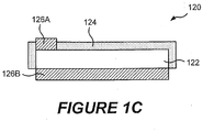
- Figure 1C illustrates a light emitter 120 including an LED chip 122 that includes top and bottom anode/cathode contacts 126A, 126B and that is coated with a wavelength conversion phosphor 124 according to some embodiments.
- the LED package 100 may include a multi-chip module as described, for example, in U.S. Patent Application Serial No. 12/154,691 filed May 23, 2008 .
- the light emitters 120A-120D may have both anode and cathode contacts on the same side of the device. Accordingly, the present invention is not limited to devices including light emitters having a vertical device structure with anode and cathode contacts on opposite sides of the device.
- the package 100 may include a submount 114 including a plurality of bondpads configured to receive a respective plurality of LED chips 120A to 120D.
- the package 100 includes a body 110 having an upper surface including a central region on which the submount 114 is positioned.
- the submount 114 includes respective pairs metal traces that provide chip and/or wire bonding pads.
- a reflector 118 may surround the central region of the body 110 and define an optical cavity above the LED chips 120A to 120D mounted on the submount 114.
- a lens 130 may be affixed over the LED chips 120A-120D to provide a desired angular emission pattern of light from the LED chips 120A-120D, and/or to increase light extraction from the LED package 100.
- the package 100 further includes a first external lead 152 that includes at least a portion 154 thereof exposed within a recess 127 in the body 110.
- the exposed portion 154 of the external lead 152 is coupled to an anode or cathode bondpad on the first LED chip 120A via a wirebond connection 156.
- the other bondpad (i.e. cathode or anode) of the first LED chip 120A is coupled to a conductive trace on the submount 114 that is coupled to a second external lead 162 via a wirebond connection 158 to a portion 160 of the second external lead 162 that is exposed within a recess 129 in the body 110 of the package 100.
- the first external lead 152 and the second external lead 162 provide respective external anode/cathode contacts for the first LED chip 120A.
- a third external lead 252 includes at least a portion 254 thereof exposed within the recess 127, The exposed portion 254 of the third external lead 252 is connected to an electrical trace via a wirebond connection 256 and then to an anode or cathode bondpad of a second LED 120C via a wirebond connection 257.
- the other (i.e. cathode or anode) bond pad of the second LED 120C is coupled to a third electrical trace, and the third electrical trace is connected to a fourth external lead 262 via a wirebond connection 259 to a portion 260 of the fourth external lead 262 exposed in the recess 129.
- the third and fourth LED chips 120B and 120D may likewise be connected to respective external leads that provide anode/cathode connections for the LED chips.
- the first and third external leads 152, 252 on one side of the package 100 may include cathode contacts, while the second and fourth external leads 162, 262 on the other side of the package 100 may include anode contacts, or vice-versa.
- the LED chips 120A to 120D may be isolated from one another, and may not share any common contacts, which may facilitate the interconnection of LED chips of adjacently mounted packages 100 into a desired configuration, such as to form series strings of LED chips.
- each of the light emitting devices 120A-120D in the package 100 may be driven independently of the other devices in the package. That is, the package may include separate anode/cathode leads for each of the LEDs 120A-120D. Having individually drivable light emitting devices may permit the LEDs to be individually controlled, for example driven at different current levels, which may enable a lighting system to compensate for brightness variations among the light emitters in a given package 100 to achieve a desired color point.
- the package 100 could include more or fewer light emitters therein.
- the light emitters 120A-120D may be covered or coated with a wavelength conversion material 124, such as a phosphor, that converts at least a portion of light emitted by the light emitters 120A-120D to a different wavelength or color.
- a wavelength conversion material 124 such as a phosphor
- the LED package 100 may include a multi-chip LED package, such as an MC-E LED available from Cree, Inc., the assignee of the present invention.
- the LED package 100 may include four phosphor coated power LED chips having dimensions of about 1000 ⁇ m x 1000 ⁇ m or more. Some embodiments provide a 7 mm x 9 mm LED package including four 1.4 mm x 1.4 mm phosphor coated power LED chips. Such a package may be capable of generating more than 1,000 lumens of light output at 700 mA using approximately 9.8 W of power. One thousand lumens is approximately equivalent to the light produced by a standard 75 watt incandescent light bulb.
- Some embodiments may provide binning and chip selection techniques for use in LED package manufacturing that may provide extremely tightly color-matched LEDs in an LED package.
- binning and chip selection techniques may provide a tighter (i.e. narrower or smaller) color distribution than previously available, allowing users to address applications with very tight color requirements and/or reducing waste of LED chips that previously could not be used in a particular packaging application.
- a color distribution can be achieved that is about 79% tighter than can be achieved with standard binning techniques.
- the light emitters 120A-120D may be grouped and/or selected for inclusion in a particular LED package 100 responsive to the combined chromaticity and/or luminous flux values of the light emitters 120A-120D. Chromaticities of the light emitters 120A-120D may be selected so that the combined light, that is a mixture of light from the light emitters 120A-120D, may have a desired chromaticity. In this manner, the perceived color of light generated by the LED package 100 may appear to have a desired chromaticity, e.g. white, based on the apparent chromaticity of the combination, even if none (or fewer than all) of the light emitters 120A-120D individually emits light having the desired chromaticity. Furthermore, in some embodiments, the luminous flux of the light emitters 120A-120D may be selected so that the combined mixture of light has a desired luminous flux level.
- Figure 2 is a two-dimensional chromaticity diagram illustrating a chromaticity region 146 within a chromaticity space 140.
- a chromaticity diagram is a two-dimensional representation of all visible colors. Each visible color, which has a distinct hue and saturation, can be represented by a point in the diagram.
- Various chromaticity spaces have been defined, including the 1931 CIE chromaticity space and the 1976 CIE chromaticity space created by the International Commission on Illumination (CIE).
- the light emitted by a light emitter 120A-120D may be represented by a point on a chromaticity diagram. Consequently, a region on a chromaticity diagram may represent light emitters having similar chromaticity coordinates.
- the chromaticity region 146 is subdivided into multiple chromaticity subregions (or simply subregions) 146A-146D.
- the subregions 146A-146D may correspond to multiple groups of light emitters having similar chromaticity coordinates.
- the chromaticity space 140 may be defined in terms of u' and v' axes 144, 142 such that any point in the color space may be expressed as a coordinate pair (u', v'). It will be appreciated that the chromaticity region 146 shown in Figure 2 may be in any desired location within the chromaticity space 140 and may have any desired size or shape.
- the size, shape and location of the chromaticity region 146 in Figure 2 are arbitrary and are shown for illustrative purposes only.
- an LED package 100 includes a plurality of N light emitters 120A-120D.
- the LED package 100 of Figure 1 is illustrated as including four (4) light emitters, it will be appreciated that N could be any number greater than two (2).
- Each of the N light emitters 120A-120D has a chromaticity that falls within one of N subregions 146A-146D defined within a chromaticity region 146.
- the combined light from the N light emitters 120A-120D may fall within a target chromaticity region 148 that is defined within and is smaller than the chromaticity region 146 within which the N subregions 146A-146D are defined.
- an LED package 100 may include first to fourth light emitters 120A to 120D that are selected based on their chromaticity points falling within one of first to fourth emitter group subregions 146A-146D.
- one of the light emitters 120A may have a chromaticity that falls within a first subregion 146A
- one of the light emitters 120B may have a chromaticity that falls within a second subregion 146B
- one of the light emitters 120C may have a chromaticity that falls within a third subregion 146C
- one of the light emitters 120D may have a chromaticity that falls within a fourth subregion 146D.
- an LED package 100 may not be necessary for an LED package 100 to include a light emitter 120A-120D from each of the defined subregions 146A-146D, depending on the chromaticities of the selected light emitters 120A-120D.
- each of the light emitters 120A-120D does not have to be in a unique subregion 146A-146D. For example, more than one of the light emitters 120A-120D may fall within a single subregion 146A-146D.
- the subregions may be defined such that each subregion in the plurality of subregions shares a boundary line with at least two other subregions. Also, each subregion may at least partially overlap the target chromaticity region 148. In some embodiments, the subregions 146A-146D may completely fill the chromaticity region 146, so that a chromaticity point in the chromaticity region 146 falls within at least one defined subregion.
- some embodiments define a chromaticity region 146 that is larger than and encompasses a target chromaticity region 148.
- the chromaticity region 146 is further divided into a plurality of N subregions 146A to 146D that are arranged in a two-dimensional matrix of subregions.
- An LED package 100 includes a plurality of N light emitters 120A to 120D, each of which has a chromaticity that falls within one of the N subregions 146A to 146D.
- the chromaticity of an individual light emitter 120A-120D may be determined based on the color of light emission from the light emitter 120A-120D without any color conversion or shifting using phosphors or other luminophoric material. Alternatively, in some embodiments, the chromaticity of an individual light emitter 120A-120D may be determined based on the combined color of light emission from the light emitter 120A-120D and of light emission from a phosphor that is stimulated by the emission from the light emitter 120A-120D.
- the light emitters 120A-120D may comprise blue and/or ultraviolet LEDs that are coated with a phosphor or phosphor-bearing material that is arranged to receive at least some light emitted by the light emitters 120A-120D and to responsively emit light having a different wavelength.
- the combined light emitted by the light emitter and the phosphor may appear white.
- Such color conversion is well known in the art.
- one or more of the light emitters 120A-120D may be coated with phosphor, while one of the light emitters 120A-120D may not be coated with phosphor.
- light emitters 120A-120D may be selected for inclusion in an LED package 100 based on their chromaticity points being about equidistant from the target chromaticity region 148, or a desired chromaticity point within the target chromaticity region 148, or being in subregions 146A-146D that are about equidistant from the desired chromaticity point or region.
- the chromaticity points of the light emitters 120A-120D need not be equidistant from the desired chromaticity point or region.
- the desired chromaticity point or region 148 may be different from the chromaticity of light emitted by some or all of the light emitters 120A-120D in the package 100.
- an LED package 100 includes four light emitters 120A-120D. Some, e.g., three, of the light emitters 120A-120C may include blue light emitting diodes coated with a yellow phosphor and having a combined light emission (chip plus phosphor) that appears yellow-green to an observer.
- white light generally refers to light having a chromaticity point that is within a 10-step MacAdam ellipse of a point on the black body locus (BBL) having a correlated color temperature (CCT) between 2700K and 6500K
- white light generally refers to light having x, y color coordinates within an area on a 1931 CIE Chromaticity Diagram defined by points having coordinates (0.32, 0.40), (0.36, 0.48), (0.43, 0.45), (0.42, 0.42), (0.36, 0.38), as described in detail in U.S. Patent No.
- the target chromaticity region 148 for combined light from the three light emitters 120A-120C may not be in a region of a chromaticity space that is conventionally designated as "white.”
- the fourth light emitter may comprise a red LED that emits light at a wavelength selected such that combined light from all four light emitters 120A-120D appears white to an observer, and in some embodiments falls along the black body locus.
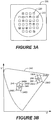
- an LED package 200 that includes multiple groups of multiple light emitters is illustrated.
- the LED package 211 includes a first group of 24 white or near-white light emitters 220 and a second group of eight red light emitters 230 for a total of 32 light emitters.
- Light emitters in each group of light emitters may be selected in accordance with embodiments of the invention.
- an LED package 200 may include a plurality of "white" LED chips 220 comprising phosphor-coated blue emitting LED chips and a plurality of red light emitting LED chips 230.
- red light refers to visible light having a dominant wavelength of about 600 nm or more.
- the white LED chips 220 may be selected from a plurality of subregions 246A-246D that are defined in a chromaticity region 246 within a chromaticity space 240 that includes a first target chromaticity region 248 for combined light emitted by the white light emitters.
- the red light emitters 230 may be selected from a plurality of subregions 256A-256D that are defined in a chromaticity region 256 that includes a second target chromaticity region 258 of combined light emitted by the red light emitters 230.
- the color of the total combined light emitted by the LED package 200 may be more consistent overall.
- the chromaticity regions 246, 256 shown in Figure 3B may be in any desired location within the chromaticity space 240 and may have any desired size or shape.
- the size, shape and location of the chromaticity regions 246, 256 in Figure 3B are arbitrary and are shown for illustrative purposes only.
- an LED package 300 may include a plurality of "white" LED chips 310 comprising phosphor-coated blue emitting LED chips, a plurality of yellow-green LED chips 320 comprising phosphor-coated blue emitting LED chips and a plurality of red emitting LED chips 330.
- the white LED chips 310 may be selected from a plurality of subregions 346A-346D that are defined in a chromaticity region 346 within a chromaticity space 340 that includes a target chromaticity region 348 of combined light emitted by the white light emitters 310.
- the yellow-green LED chips 320 may be selected from a plurality of subregions 356A-356D that are defined in a chromaticity region 356 of the chromaticity space 340 that includes a target chromaticity region 358 of combined light emitted by the yellow-green light emitters.
- the red LED chips 330 may be selected from a plurality of subregions 366A-366D that are defined in a chromaticity region 366 of the chromaticity space 340 that includes a target chromaticity region 368 of combined light emitted by the red light emitters 330.
- the respective combined colors of the white, yellow-green and red light emitters may fall within the target chromaticity regions 348, 358. 368. Accordingly, the color of combined light emitted by the LED package 300 may be more consistent.
- chromaticity regions 346, 356 and 366 shown in Figure 4B may be in any desired location within the chromaticity space 340 and may have any desired size or shape.
- the size, shape and location of the chromaticity regions 346, 356, 366 in Figure 4B are arbitrary and are shown for illustrative purposes only.
- a luminaire 410 according to some embodiments is illustrated.
- the luminaire 410 shown in Figures 4C and 4D is a "can" lighting fixture that may be suitable for use in general illumination applications as a down light or spot light.
- a lighting apparatus may have a different form factor.
- a luminaire according to some embodiments can have the shape of a conventional light bulb, a pan or tray light, an automotive headlamp, a conical shape, or any other suitable form.
- the luminaire 410 generally includes a cylindrical outer housing 412 in which a lighting panel 440 is arranged.
- the lighting panel 440 has a generally circular shape so as to fit within an interior of the cylindrical housing 412.
- Light is generated by solid state lighting devices (LEDs) 120A to 120D, which are mounted on the lighting panel 440, and which are arranged to emit light 415 towards a diffusing lens 414 mounted at the end of the housing 412.
- Diffused light 417 is emitted through the lens 414.
- the lens 414 may not diffuse the emitted light 415, but may redirect and/or focus the emitted light 415 in a desired near-field or far-field pattern.
- the LEDs 120A to 120D in the luminaire 410 may include white emitting LEDs.
- the LEDs 120A to 120D in the luminaire 410 may be electrically interconnected in respective strings 423A to 423D, as illustrated in the schematic circuit diagram in Figure 4D .
- Each string 423A to 423D may be connected to a respective anode terminal 427A to 427D and a cathode terminal 429A to 429D.
- luminaire 410 may include more or fewer strings.
- luminaire 410 may include other strings, such as strings of red emitting LEDs that may be provided to alter the chromaticity of the combined light emitted by the luminaire 410.
- a lighting panel 440 including a plurality of LEDs 120A to 120D mounted thereon is illustrated.
- the LEDs 120A to 120D having different chromaticities may be distributed about evenly over the surface of the lighting panel 440 for spatial color balance.
- any arbitrary square grouping 121 of four neighboring LEDs 120A to 120D on the panel 440 may include one each of the LEDs 120A, 120B, 120C and 120D.
- a target chromaticity region 148 can be defined as a region that is within and encompassed by a chromaticity region 146 that is defined in the proposed ANSI standard C78.377A for chromaticity of solid state light emitting devices.
- the chromaticity region 146 may encompass a point on the black body locus (BBL) having a color temperature of about 3050K.
- BBL black body locus
- Figure 5 illustrates a chromaticity region 146 as represented on a 1976 CIE u'v' chromaticity diagram
- the chromaticity region 146 may correspond to a region encompassing a point on the BBL of a 1931 CIE x,y chromaticity diagram.
- the chromaticity region 146 may be bounded by a quadrilateral defined by points having the following (x,y) coordinates on a 1931 CIE chromaticity x,y diagram: A (0.4147,0.3814); B (0.4299,0.4165); C (0.4562,0.4260); D (0.4373,0.3893).
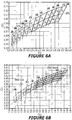
- FIG. 6A A plurality of possible chromaticity regions, as represented on 1931 CIE chromaticity diagrams, are illustrated in Figure 6A , on which emitter group regions 3A-3D, 4A-4D, 5A-5D, 6A-6D and 7A-7D are shown.
- a desired emitter group region may be defined by a standard, such as the ANSI C78.377A LED binning standard.
- a standard such as the ANSI C78.377A LED binning standard.
- a standard chromaticity region or bin
- only light emitters that fall within the standard bin are chosen for inclusion within the package, and other light emitters that do not fall within the standard bin are discarded or ignored.
- some embodiments enable the selection and use of light emitters having chromaticity points that fall outside a standard bin to be used in a package that emits combined light having a chromaticity point within the standard bin, and in some cases, within a chromaticity region that is even smaller than the standard bin.
- a "bin” refers to a defined region of a chromaticity space.
- LEDs are sorted into defined bins for manufacturing purposes based on the chromaticity of light emitted by the LEDs, in a process referred to as "binning.”
- bins are defined as quadrangles that encompass a 7-step MacAdam ellipse, which is the standard tolerance defined for compact fluorescent lamps by the Department of Energy Energy Star program.
- MacAdam ellipse which is the standard tolerance defined for compact fluorescent lamps by the Department of Energy Energy Star program.
- some chromaticity points that fall within the bin may nevertheless fall outside the 7 step MacAdam ellipse used to defined the bin.
- bins can be defined as shapes other than quadrangles. For example, bins could be defined as ellipses such as MacAdam ellipses, triangles, circles or any other geometric shape. Furthermore, bins can be defined in any color space, including a 1931 CIE (x,y) color space, a 1976 CIE (u',v') color space, or any other color space.
- the standard bins can be further subdivided into even smaller bins that can be used to define chromaticities.
- Figure 6B illustrates standard chromaticity bins defined according to the ANSI C78.377A LED binning standard that have been further subdivided into smaller bins. Smaller bins offer improved color consistency among LED lighting fixtures.
- 4 sub-bins may be defined within each ANSI quadrangle.
- one or more of the warm/neutral ANSI quadrangles may be sub-divided into 16 discrete bins, each of which may be 94 percent smaller than the quadrangles defined in the ANSI C78.377A LED binning standard.
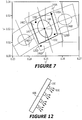
- a standard bin 150 defined in the ANSI C78.377A LED binning standard is shown.
- a chromaticity region 146 is defined.
- the chromaticity region 146 may defined as contiguous with the defined bin 150 in some embodiments.
- the chromaticity region 146 may be larger than and encompass the defined bin 150, such that the defined bin 150 is a subset of the chromaticity region 146.
- the chromaticity region 146 illustrated in Figure 7 is a quadrangle, it will be appreciated that other geometric shapes may be used to define the chromaticity region.
- the chromaticity region 146 is further subdivided into a plurality of subregions 146A-146D, each of which may at least partially overlap the standard bin 150. However, subregions may be defined that do not overlap the standard bin 150. Light emitters 120A-120D having chromaticities within one or more of the defined subregions 146A-146D may then be selected for inclusion in an LED package.
- the light emitters 120A-120D may, for example, have respective chromaticity points at the points indicated in Figure 7 .
- the chromaticity point of light emitter 120A is within the subregion 146A, but is on the edge of the defined bin 150.
- the chromaticity point of the light emitter 120B is within the subregion 146B and within the desired bin 150.
- the chromaticity point of the light emitter 120C is within the subregion 146C and within the desired bin 150.
- the chromaticity point of light emitter 120D is within the subregion 146D, but is outside the desired bin 150.
- the combined light emitted by all four light emitters 120A-120D may be within the desired bin 150, and may be within an even smaller target chromaticity region 148 that is within the defined bin 150.
- a target chromaticity region 148 can be obtained according to some embodiments that approximates a 4-step MacAdam ellipse, thereby providing significantly better color purity compared to a package that is simply specified as falling within the ANSI-specified bin.
- a chromaticity region is defined that encompasses a defined bin.
- the chromaticity region is divided into subregions, each of which at least partially overlaps the defined bin.
- Light emitters are selected from the subregions for inclusion within an LED package.
- subregions 146A and 146D are complementary subregions, since they are disposed opposite one another relative to a center point 145 of the defined bin 150
- subregions 146C and 146B are complementary subregions.
- the final combined light output by a packaged LED 100 may be more consistent (i.e. more tightly grouped) than if the light emitters had simply been selected from an arbitrary point within the chromaticity region.
- grouping of combined light chromaticities may be obtained to within a four step, or even a two-step, MacAdam ellipse, which may provide an improvement of up to 79% or more relative to conventional bin sizes.
- the target chromaticity region 148 can be determined as the union of all possible chromaticity points of light that is generated by a combination of one light emitter from each of the subregions 146A-146D.
- the outer perimeter of the target chromaticity region 148 can be determined by combining light from four different light emitters at the extreme points of the respective subregions 146-146D. For example, referring to Figure 8A , assuming equal luminous flux, light emitters 120A-120D having chromaticity points at the extreme positions shown therein will generate combined light having a chromaticity point 160A.
- Figure 8A represents a worst-case or most extreme scenario of chromaticity points for the four light emitters. However, as illustrated in Figure 8A , the chromaticity point 160A of the combined light may still fall well within the defined bin 150
- the size of the chromaticity region 146 which can be used to define the bins 146A-146D from which light emitters are selected, can be determined so that any combination of light emitters from the four different subregions 146A-146D will not generate combined light having a chromaticity point that falls outside the defined bin 150. That is, the size of the chromaticity region 146 can be selected so that the target chromaticity region 148 touches an edge of the defined bin 150, as illustrated in Figure 8C .
- an LED package 100 can generate combined light having a chromaticity that is inside a desired bin even though the package 100 includes one or more light emitters having chromaticities outside the desired bin.
- This approach can provide significant flexibility to an LED package manufacturer, because it enables the use of larger bins of light emitters than was previously possible. This can reduce waste and inefficiency in the packaging process, because there may be fewer unusable parts compared to a manufacturing process in which only light emitters from a defined bin are selected for inclusion in a package designed to emit light having a color point within the region occupied by the defined bin.
- a pick and place device 500 is configured to accept a plurality of die sheets 510A to 510D.
- Each of the die sheets 510A to 510D includes light emitters 120A to 120D that emit light that falls within one of the subregions 146A to 146D of the chromaticity region 146.
- light emitters 120A on the die sheet 510A may emit light that falls within the first subregion 146A of the chromaticity region 146
- light emitters 120B on the die sheet 510B may emit light that falls within the second subregion 146B of the chromaticity region 146, etc.
- the pick and place device 500 may accept a single die sheet 510A that includes light emitters from each of the subregions 146A-146D along with an electronic die map 520 containing information about the chromaticities of the various die on the die sheet 510A.
- one or more of the die sheets 510A-510D may contain light emitters that include LED die that have been coated with a phosphor containing material.
- the pick and place device 500 also receives a plurality of package bodies 110, for example on a tape reel.
- the pick and place device 500 may select one light emitter 120A-120D from each of the die sheets 510A-510D and mount it on a single package body 110.
- the package body 110 including the four light emitters 120A-120D is then output by the pick and place device 500 to a subsequent processing device, for example, to coat the light emitters 120A-120D with an encapsulant, to affix a lens onto the package body 110, or to perform some other action.
- a manufacturing process can facilitate efficient assembly of an LED package 100 that includes light emitters selected to generate a combined light that falls within a target chromaticity region.
- luminous flux may be considered in grouping the light emitters 120.
- Figure 10 is a table illustrating luminous flux bin values according to some embodiments of the present invention.
- the light emitters 120 may be grouped according to their luminous flux using multiple luminous flux ranges.
- three luminous flux bins identified as VI, V2, and V3 may correspond to ranges 100 lm to 110 lm, 110 lm to 120 lm, and 120 lm to 130 lm, respectively.
- emitter groups may be defined as falling within a specific chromaticity subregion at a specific luminous flux range.
- an emitter group may include all light emitters 120 having chromaticity corresponding to chromaticity subregion 146C and luminous flux V2.
- the light emitters 120 may be grouped responsive to a combined chromaticity of a portion of multiple bins that may be defined corresponding to multiple chromaticity regions and multiple luminous flux ranges.
- FIG. 11 is a chromaticity diagram illustrating multiple chromaticity regions and a target chromaticity region according to some embodiments of the present invention.
- a portion of 1931 CIE chromaticity space 460 includes an x axis 464 and a y axis 462.
- Light emitters 120 may be sorted into multiple chromaticity subregions 468 according to the chromaticity of light emitted therefrom.
- the chromaticity regions 468 may fall within a region that is generally considered to constitute white light.
- a target chromaticity region 470 may include a portion of the chromaticity region 460 that is specified corresponding to a design specification and/or a particular application.
- the target chromaticity region 470 may be expressed in terms of chromaticity coordinates.
- a tolerance color region 472 may be larger than the target chromaticity region 470 due to variations between individual emitters within each of the subregions 468.
- each of the emitter group regions 468 may include a center point that may be determined as a function of chromaticity values.
- the emitters may be further grouped corresponding to luminous flux.
- each of the bins may be expressed, for example, in terms of x, y, and Y, such that chromaticity of each of the bins may be expressed as center point x, y coordinates and the luminous flux may be expressed as Y.
- a combined chromaticity corresponding to emitters from two bins may be determined using the chromaticity and luminous flux center point values corresponding to the two bins.
- combinations that produce a luminous flux below a specified range may be discarded.
- the luminous flux values of the bins are such that a combined luminous flux is necessarily within a specified range. For example, if the minimum bin luminous flux is V1 and the specified range includes V1 luminosities, then all of the combinations necessarily are within the specified range.
- the disclosure herein specifically addresses two bin combinations, the invention is not thus limited. For example, combinations including three or more bins may also be used according to the methods, devices and apparatus disclosed herein.
- the combined chromaticity of each two-bin combination may be compared to a target chromaticity region 470 to determine which of the combinations to discard. For example, if a combined chromaticity is located in emitter group region A3 then that combination may be discarded. In this manner, the combinations that provide sufficient luminous flux and chromaticity may be considered when selecting the light emitters 120 from corresponding ones of those bins.
- the multiple bins may be prioritized based on, for example, proximity to the target chromaticity region 470. For example, bins that are farther from the desired color region may be assigned a higher priority than bins that are nearer to the desired color region. In this manner, subregion A9 may be assigned a higher priority than subregion C3. In some embodiments, combination center points may then be prioritized corresponding to the bin priorities.
- the combination center points may be prioritized based on locations of the combination center points relative to a target chromaticity point in the target chromaticity region 470.
- the target chromaticity may be dependent on the geometry of desired color region, such as, for example, a center and/or other focus point of the target chromaticity region 470.
- the light emitters 120 are selected from a batch or inventory of light emitters that are grouped into the bins and the target chromaticity point may correlate to chromaticity and/or luminous flux data of the emitter inventory.
- a lighting panel 600 includes a plurality of LED packages 100 as described herein that are mounted on a first side of the panel 600 and that emit light combined 610 having a chromaticity within a target chromaticity region for use in general lighting applications.
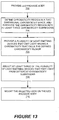
- Figure 13 is a flowchart illustrating operations according to some embodiments.
- methods of forming a light emitting device package assembly include providing a light emitting device package body (Block 702), defining a chromaticity region in a two dimensional chromaticity space and subdividing the defined chromaticity region into at least three chromaticity subregions (Block 704), and providing a plurality of light emitting devices that emit light having a chromaticity that falls within the defined chromaticity region (Block 706).
- At least three of the plurality of light emitting devices are selected for mounting on the light emitting device package body, wherein each of the three light emitting devices emits light from a different one of the chromaticity subregions (Block 708). Finally, the selected LEDs are mounted on the package body (Block 710)
- the methods may further include defining a second chromaticity region in a two dimensional chromaticity space and subdividing the second chromaticity region into at least three second chromaticity subregions, providing a second plurality of light emitting devices that emit light having a chromaticity that falls within at least one of the second chromaticity subregions, and selecting at least three of the second plurality of light emitting devices, wherein each of the three light emitting devices of the second plurality of light emitting devices emits light from a different one of the second chromaticity subregions.
- the selected light emitting devices of the second plurality of light emitting devices are mounted on the light emitting device package body. Accordingly, the operations illustrated in Blocks 702 to 710 of Figure 13 can be repeated and/or performed concurrently for a second or subsequent chromaticity regions.
- the defined subregions may include a plurality of pairs of complementary subregions with respective subregions in a pair of complementary subregions arranged opposite a center point of the chromaticity region from one another.
- the methods may further include selecting at least four of the plurality of light emitting devices from at least four chromaticity subregions in pairs from respective pairs of complementary subregions.
- the methods may include selecting a first light emitting device having a first luminous flux from a first subregion that has a center point that is located a first distance from a center point of the chromaticity region, and selecting a second light emitting device having a second luminous flux from a second subregion that is complementary to the first subregion and that has a center point that is located a second distance from a center point of the chromaticity region.
- the first distance may be smaller than the second distance and the first luminous flux may be larger than the second luminous flux, so that combined light emitted by the pair of light emitting device from complementary subregions may fall within the target chromaticity region, as illustrated in Figure 11 .
- a white LED package assembly having a tunable color point can be formed by providing a plurality of light emitting devices having chromaticities that fall within different chromaticity regions and separately controlling the plurality of light emitting devices to emit light at different intensities.
- a single luminaire may include light emitting devices that are binned in different "white" bins, which may include both warm and cold white bins.
- differently-binned light emitting devices can be provided in a single LED package assembly and/or separate LED package assemblies in a luminaire.
- a luminaire according to some embodiments can include a plurality of strings of LEDs, wherein each of the strings includes LEDs from a same chromaticity region, and different strings emit light in different ones of the chromaticity regions.
- Chromaticity of the combined light emitted by a single package assembly and/or luminaire assembly including differently binned LEDs can be tuned to fall within a chromaticity region defined by the chromaticity points of the LEDs in the assembly by adjusting the relative intensity of light emitted by the LEDs.
- FIG. 14 which illustrates a plurality of possible chromaticity regions as represented on a 1931 CIE chromaticity diagram
- four chromaticity regions, or bins, 810A to 810D are identified.
- An LED package assembly such as the LED package assembly 100 shown in Figure 1A may include four white light emitting LEDs 120A-120D, in which respective ones of the LEDs 120A to 120D are selected from LEDs falling within the four chromaticity regions 810A to 810D shown in Figure 14 .
- LED 120A may emit light when energized that falls within chromaticity region 810A
- LED 120B may emit light when energized that falls within chromaticity region 810B
- LED 120C may emit light when energized that falls within chromaticity region 810C
- LED 120D may emit light when energized that falls within chromaticity region 810D.
- Color points of the LEDs 120A to 120D are illustrated in Figure 14 .
- Each of the chromaticity regions 810A to 810D may have a size that is about equal to a seven step MacAdam ellipse.
- the four chromaticity regions 810A to 810D may be spaced apart from one another in the two-dimensional chromaticity space to define a tuning region 820 illustrated as a polygon formed with the specific color points of the LEDs 120A to 120D as the vertices of the polygon.
- the four chromaticity regions 810A to 810D may be spaced apart from one another by respective regions that are at least the size of a seven step MacAdam ellipse. Stated differently, a region between any two of the chromaticity regions 810A to 810D may be at least large enough that a seven step MacAdam ellipse can fit therein.
- the four chromaticity regions 810A to 810D may be spaced apart from one another by respective regions that are at least the size of a fourteen step MacAdam ellipse, and in still further embodiments, the four chromaticity regions 810A to 810D may be spaced apart from one another by respective regions that are at least the size of a twenty step MacAdam ellipse.
- the color point of the package assembly 100 can be shifted to any point within the tuning region 820.
- the intensity of the light emitted by any one of the LEDs 120A to 120D can be varied by adjusting the average current passing through the LEDs. Adjusting the average level of current passing through LEDs 120A to 120D can be performed by adjusting a steady state level of DC current passing through the LEDs. In some embodiments, the average level of current passing through an LED can be adjusted by adjusting the duty cycle of a pulse width modulation (PWM) and/or pulse frequency modulation (PFM) drive current that is passed through the LEDs.
- PWM pulse width modulation
- PFM pulse frequency modulation
- the light output characteristics of an LED may change in response to changes in the level of DC current supplied to the device.
- an LED driven at 20 mA may have a different chromaticity point than when the same LED is driven at 100 mA.
- the tuning region 820 may include chromaticity regions that are generally considered to be "white” (i.e., the regions enclosed in polygons) and may also include some non-white regions.
- the chromaticity regions 810A to 810D include two "cool white” regions 810A and 810B and two “warm white” regions 810C and 810D.
- warm white and cool white are based on the appearance of the light to an observer, not on the correlated color temperature (CCT) of the light.
- CCT correlated color temperature
- the two warm LEDs 120A and 120B may be positioned in the package 100 diagonally opposite one another, while the two cool LEDs 120C and 120D may be positioned in the package 100 diagonally opposite one another, which may balance or equalize the far-field emission characteristics of the package so that the combined light observed in the far field will appear to be a homogeneous mixture of warm and cool light.
- the two cool white LEDs 120A, 120B have CCTs that are greater than 5000K, and in particular are greater than 5700K, and even more particularly are greater than 6500K.
- the two warm white LEDs 120C, 120D have CCTs that are less than 5000K, and in particular are less than 3500K, and even more particularly are less than 3000K.
- the two cool white LEDs 120A, 120B have chromaticity points on opposite sides of the black body locus BBL from one another.
- the two warm white LEDs 120C, 120D have chromaticity points on opposite sides of the black body locus from one another.
- the tuning region 820 may enclose at least some portions of the black body locus. Furthermore, the combined light emitted by the LEDs 120A to 120D can have a correlated color temperature that is tunable from less than about 2700K to greater than about 6500K or more.
- none of the chromaticity regions 810A to 810D may overlap the black body locus.
- the tuning region defined by particular LEDs having color points within the chromaticity regions 810A to 810D may enclose at least a portion or portions of the black body locus.
- combined light emitted by the LEDs 120A to 120D may fall within a 7-step MacAdam ellipse of a point on the black body locus.
- the first and second chromaticity regions 810A, 810B include light having x, y color coordinates within an area on a 1931 CIE Chromaticity Diagram defined by points having coordinates of (0.3080, 0.3110), (0.3010, 0.3420), (0.3290, 0.3690), and (0.3290, 0.3300).
- the third and fourth chromaticity regions 810C, 810D may include light having x, y color coordinates within an area on a 1931 CIE Chromaticity Diagram defined by points having coordinates of (0.4373, 0.3893), (0.4562, 0.4260), (0.4813, 0.4319), and (0.4593, 0.3944).
- Independent driving of LEDs in a package assembly 100 may be obtained by providing at least one isolated lead for each LED in the package assembly, as illustrated in Figure 1A .
- Individual drive and/or control circuitry may be provided within the luminaire for each LED in the package.
- corresponding LEDs in different packages may be connected in respective series strings (as shown in Figure 4D ) that can be driven by individual drive/control circuitry in the luminaire.
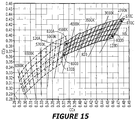
- each of the chromaticity regions 830A to 830D may include light having a CCT that is less than 5000K, and in some embodiments may include light having a CCT that is less than 4500K. Such an embodiment may be referred to as a tunable warm white device or apparatus.
- all of the chromaticity regions may include light having a CCT that is greater than 4000K. Such an example may be referred to as a tunable cool white device or apparatus.
- all of the chromaticity regions may include light having a CCT between 2700K and 5000K.
- FIG. 16 Still further embodiments are illustrated in Figure 16 , in which a plurality of possible chromaticity regions, as represented on a 1931 CIE chromaticity diagram, are illustrated to include three chromaticity regions 850A to 850C.
- LEDs 120A to 120C have chromaticity points that fall within respective ones of the chromaticity regions 830A to 830C and define a triangular tuning region 860.
- the first LED 120A may have a chromaticity point that falls within a chromaticity region 850A that encompasses a portion of the black body locus BBL.
- the two LEDs 120B, 120C have chromaticity points on opposite sides of the black body locus BBL from one another.
- the LEDs 120A to 120D in an LED package assembly may include LEDs having different color rendering characteristics.
- at least one of the LEDs 120A to 120D may have a relatively low color rendering index (CRI) (e.g., less than 85), while at least one other of the LEDs 120A to 120D may have a relatively high CRI (e.g., greater than 85).
- CRI color rendering index
- two of the LEDs may have a CRI less than 85 and two of the LEDs may have a CRI greater than 85.
- a first plurality of LEDs in a package may have an average CRI that is about 10 points greater than an average CRI of a second plurality of LEDs in the package.
- two of the LEDs in a package assembly may have a CRI of about 90 and two of the LEDs in the package assembly may have a CRI of about 80, in which case an average CRI of the combined light emitted by the LED package assembly when energized may be about 85.
- a first plurality of LEDs in a solid state lighting apparatus may have an average CRI that is about 10 points greater than an average CRI of a second plurality of LEDs in the apparatus.
- high CRI devices are typically relatively dimmer than low CRI devices, which may be due to the inclusion of more phosphor material in the high CRI device.
- brightness and CRI for some types of solid state devices.
- the high CRI devices may be driven at higher average current than the low CRI devices to offset the loss of brightness associated with the increase in CRI.
- Some embodiments of the invention provide a lighting panel having two or more strings of LED chips connected in electrical series, as illustrated in Figure 4D .
- An independent current control circuit may be provided for each of the strings of LED chips.
- current to each of the strings may be individually controlled, for example, by means of pulse width modulation (PWM) and/or pulse frequency modulation (PFM).
- PWM pulse width modulation
- PFM pulse frequency modulation
- the width of pulses applied to a particular string in a PWM scheme (or the frequency of pulses in a PFM scheme) may be based on a prestored pulse width (frequency) value that may be modified during operation based, for example, on a user input and/or a sensor input.
- the luminaire 900 which may be a lighting fixture for general illumination, includes a lighting panel 440, which may, for example, include a circular panel provided within a recess can light as illustrated in Figure 4C .
- the panel 440 may include first to fourth strings of white light emitting diodes 423A to 423D each of which may include LEDs selected from respective bins corresponding to chromaticity regions as illustrated in Figure 14 .
- a first string 423A may include LEDs 120A selected from a first chromaticity region or bin 810A
- a second string 423B may include LEDs 120B selected from a second chromaticity region or bin 810B, and so on.
- a current driver 920 provides independent current control for each of the LED strings 923 of the lighting panel 940.
- the current driver 920 may provide a constant current source for each of the LED strings of the lighting panel 440 under the control of a controller 930.
- the controller 930 may be implemented using an 8-bit microcontroller such as a PIC18F8722 from Microchip Technology Inc., which may be programmed to provide pulse width modulation (PWM) control of separate current supply blocks within the driver 920 for the LED strings 423A to 423D.
- PWM pulse width modulation
- Pulse width information for each of the LED strings may be obtained by the controller 930 from a color management unit 960, which may in some embodiments include a color management controller such as the Agilent HDJD-J822-SCR00 color management controller.
- the color management unit 960 may be connected to the controller 930 through an I2C (Inter-Integrated Circuit) communication link 935.
- the color management unit 960 may be configured as a slave device on an I2C communication link 935, while the controller 930 may be configured as a master device on the link 935.
- I2C communication links provide a low-speed signaling protocol for communication between integrated circuit devices.
- the controller 930, the color management unit 960 and the communication link 935 may together form a feedback control system configured to control the light output from the lighting panel 440.
- the controller 930 may include registers R1-R4, which may correspond to internal registers in the controller 930 and/or may correspond to memory locations in a memory device (not shown) accessible by the controller 930.
- the controller 930 may include a register for each LED string 423A-423D.
- Each of the registers is configured to store pulse width information for a corresponding one of the LED strings 423A-423D.
- the initial values in the registers may be determined by an initialization/calibration process. However, the register values may be adaptively changed over time based on user input 950 and/or input from one or more photosensors 940 coupled to the lighting panel 440.
- the photosensor 940 may include, for example, an Agilent HDJD-S831-QT333 tricolor photo sensor.
- Sensor outputs from the photosensor 940 may be provided to the color management unit 960, which may be configured to sample such outputs and to provide the sampled values to the controller 930 in order to adjust the register values for corresponding LED strings 423A-423D in order to adjust light output on a string-by-string basis.
- the user input 950 may be configured to permit a user to selectively adjust a desired attribute of the lighting panel 440, such as color temperature, chromaticity point, etc., by means of user controls, such as input controls on a remote control panel.
- a current driver 920 may include a plurality of driver circuits 925A - 925D.
- One driver circuit 925A-925D may be provided for each string 423A-423D in a lighting panel 440. Operation of the current supply circuits 925A-925B may be controlled by control signals 942 from the controller 930.
- methods of operating a solid state luminaire include independently controlling current through respective first, second and third strings of white light emitting diodes to generate combined white light having a chromaticity point that is within a tuning region defined by first, second and third chromaticity regions from which LEDs of the respective strings are selected.
- the methods may further include measuring the chromaticity of the combined light, and altering current through at least one of the first, second and third strings of white light emitting diodes in response to the measured chromaticity to cause the luminaire to emit combined light having a desired chromaticity.
- the methods may include providing a solid state luminaire including respective first, second and third strings of white light emitting diodes (Block 1002), and generating combined white light from the white light emitting diodes having a chromaticity point that is within a tuning region defined by first, second and third chromaticity regions from which LEDs of the respective strings are selected (Block 1004). Chromaticity of the combined light is measured (Block 1006), and the methods further include altering current through at least one of the first, second and third strings of white light emitting diodes in response to the measured chromaticity to cause the luminaire to emit combined light having a desired chromaticity (Block 1008).
- FIG. 20 is a graph of intensity versus color temperature (CCT) for LEDs according to some embodiments.
- CCT color temperature
- the intensity of the combined light may vary from a high intensity when all of the LEDs are on (for example to tune to a color point near the center of the tuning region) to a low intensity when only a subset of the LEDs are on (for example, to tune to a color point near the maximum or minimum CCT of the tuning region).
- FIG. 1A For example, consider an LED package assembly 100 as illustrated in Figure 1A in which the four LEDs 120A to 120D are selected from respective chromaticity regions 830A to 830D as shown in Figure 15 .
- the tuning region for such a device spans a CCT range of about 4000K to about 2700K.
- substantially all of the light emission from the package assembly 100 will be from only two of the LEDs, namely LEDs 120C and 120D.
- the light emission intensities of the LEDs 120A to 120D are independently adjusted to generate a combined light having a CCT of 4000K, substantially all of the light emission from the package assembly 100 will be from LEDs 120A and 120B. However, when the light emission intensities of the LEDs 120A to 120D are independently adjusted to generate a combined light having a CCT of 3200K (near the center of the tuning region 820), all four LEDs 120A to 120D will contribute to the combined light emission. Accordingly, the total luminous flux from the package 100 may appear to brighten, and then dim, as the light output is tuned from 4000K to 2700K.
- the intensity of light emission from each LED may be adjusted to be greater near the extrema of the CCT range and lower near the middle of the CCT range, as illustrated by curve 1100 in Figure 20 .
- the light emission intensity for a given LED may vary from a maximum intensity Imax when the devce is tuned to a CCT near the ends of the CCT range down to a minimum intensity Imin when the device is tuned near the middle of the CCT range.
- the intensity of emission from a given LED may be varied by changing the drive current level, the average drive current level, the duty cycle of a PWM or PFM current drive signal, etc.
- the variation in intensity may be linear with CCT.
- a desired variation characteristic may be determined empirically and stored in the luminaire, for example, in a lookup table.
Landscapes
- Engineering & Computer Science (AREA)
- Physics & Mathematics (AREA)
- Microelectronics & Electronic Packaging (AREA)
- Optics & Photonics (AREA)
- General Engineering & Computer Science (AREA)
- Manufacturing & Machinery (AREA)
- Led Device Packages (AREA)
Claims (16)
- Lichtemittierende Vorrichtungsverpackungsanordnung (100) umfassend:einen lichtemittierende Vorrichtungsverpackungskörper (110); underste, zweite und dritte Weißlicht-emittierende Vorrichtungen (120A-120D) auf dem Verpackungskörper,wobei jede der ersten, zweiten und dritten Weißlicht-emittierenden Vorrichtungen eine Phosphor-konvertierte lichtemittierende Vorrichtung ist, wobei jede der ersten, zweiten und dritten Weißlicht-emittierenden Vorrichtungen Licht emittiert, das einen Chromatizitätspunkt aufweist, der innerhalb einer 10-stufigen Mac-Adam-Ellipse eines Punktes auf dem schwarzen Körperort, BBL, mit einer korrelierte Farbtemperatur, CCT, zwischen 2700K und 6500K liegt, und jedes Licht eine Chromatizität aufweist, die jeweils in einen ersten, zweiten und dritten nicht überlappenden Chromatizitätsbereich in einem zweidimensionalen Chromatizitätsraum fällt,wobei der erste, zweite und dritte Chromatizitätsbereich in dem zweidimensionalen Chromatizitätsraum jeweils durch Bereiche mit mindestens der Größe einer siebenstufigen Mac-Adam-Ellipse beabstandet sind, undwobei die ersten und zweiten Chromatizitätsbereiche Weißlicht mit einer korrelierten Farbtemperatur von nicht größer als 3000 K umfassen und der dritte Chromatizitätsbereich Licht mit einer Farbtemperatur von nicht weniger als 3000 K umfasst.
- Lichtemittierende Vorrichtungsverpackungsanordnung nach Anspruch 1, wobei der erste Chromatizitätsbereich Licht mit einer Chromatizität umfasst, die auf eine erste Seite eines schwarzen Körperorts in dem zweidimensionalen Chromatizitätsraum fällt, und wobei der zweite Chromatizitätsbereich Licht mit einer Chromatizität umfasst, die auf eine zweite, der ersten Seite gegenüberliegende Seite des schwarzen Körperorts in dem zweidimensionalen Chromatizitätsraum fällt.
- Lichtemittierende Vorrichtungsverpackungsanordnung nach Anspruch 1, wobei der dritte Chromatizitätsbereich Licht mit einer Farbtemperatur von nicht weniger als 4500 K umfasst.
- Lichtemittierende Vorrichtungsverpackungsanordnung nach Anspruch 1, weiterhin umfassend eine vierte Weißlicht-emittierende Vorrichtung (120A-120D) auf dem Verpackungskörper, wobei die vierte Weißlicht-emittierende Vorrichtung bei Erregung Licht mit einer Chromatizität emittiert, die in einen vierten Chromatizitätsbereich in dem zweidimensionalen Chromatizitätsraum fällt, der mit dem ersten, zweiten und dritten Chromatizitätsbereich nicht überlappend ist und der von dem ersten, zweiten und dritten Chromatizitätsbereich jeweils durch Bereiche mit mindestens der Größe einer siebenstufigen MacAdam-Ellipse beabstandet ist; wobei der dritte Chromatizitätsbereich Licht mit einer Chromatizität umfasst, die auf die erste Seite eines schwarzen Körperorts in dem zweidimensionalen Chromatizitätsraum fällt, und wobei der vierte Chromatizitätsbereich Licht mit einer Chromatizität umfasst, die auf die zweite Seite des schwarzen Körperorts in dem zweidimensionalen Chromatizitätsraum fällt.
- Lichtemittierende Vorrichtungsverpackungsanordnung nach Anspruch 1, wobei kombiniertes Licht von der ersten, zweiten und dritten Weißlicht-emittierenden Vorrichtung (120A-120D) in eine 7-stufige MacAdam-Ellipse eines Punktes auf dem schwarzen Körperort fällt.
- Festkörperleuchte, die eine lichtemittierende Vorrichtungsverpackungsanordnung (100) nach Anspruch 1 einschließt.
- Lichtemittierende Vorrichtungsverpackungsanordnung nach Anspruch 1, wobei mindestens eine der ersten, zweiten und dritten Weißlicht-emittierenden Vorrichtungen (120A-120D) einen Farbwiedergabeindex aufweist, der mindestens etwa 10 Punkte größer ist als ein Farbwiedergabeindex einer anderen der ersten, zweiten und dritten Weißlicht-emittierenden Vorrichtungen.
- Lichtemittierende Vorrichtungsverpackungsanordnung nach Anspruch 1, wobei die Chromatizität des kombinierten Lichts, das von der lichtemittierende Diodeneinheit ausgegeben wird, auf mindestens einen von einer Vielzahl von Punkten innerhalb eines Abstimmbereichs innerhalb eines zweidimensionalen Chromatizitätsraums abstimmbar ist, der durch mindestens die Chromatizität der ersten, zweiten und dritten lichtemittierenden Vorrichtungen definiert ist.
- Verfahren, umfassend:Bereitstellen eines lichtemittierenden Vorrichtungsverpackungskörpers (110); Definieren erster, zweiter und dritter nicht überlappender Chromatizitätsbereiche in einem zweidimensionalen Chromatizitätsraum, wobei die ersten, zweiten und dritten Chromatizitätsbereiche in dem zweidimensionalen Chromatizitätsraum jeweils durch Bereiche mit mindestens der Größe einer siebenstufigen MacAdam-Ellipse beabstandet sind und wobei die ersten und zweiten Chromatizitätsbereiche Weißlicht mit einer korrelierten Farbtemperatur von nicht größer als 3000 K umfassen und der dritte Chromatizitätsbereich Licht mit einer Farbtemperatur von nicht weniger als 3000 K umfasst;Bereitstellen einer Vielzahl von Weißlicht-emittierenden Vorrichtungen, die Licht mit einer Chromatizität emittieren, die in die definierten Chromatizitätsbereiche fällt, wobei die Vielzahl von Weißlicht-emittierenden Vorrichtungen Phosphor-konvertierte lichtemittierende Vorrichtungen (120A-120D) sind;Auswählen erster, zweiter und dritter lichtemittierender Vorrichtungen aus der Vielzahl Weißlicht-emittierender Vorrichtungen, wobei jede der ersten, zweiten und dritten lichtemittierenden Vorrichtungen Licht von einer anderen der definierten Chromatizitätsbereichen emittiert und das Licht einen Chromatizitätspunkt aufweist, der innerhalb einer 10-stufigen MacAdam-Ellipse eines Punktes auf dem schwarzen Körperort, BBL, mit einer korrelierten Farbtemperatur, CCT, zwischen 2700K und 6500K, und dem Licht liegt; undAnbringen der ausgewählten Weißlicht-emittierenden Vorrichtungen auf dem lichtemittierenden Vorrichtungsverpackungskörper.
- Verfahren nach Anspruch 9, wobei der erste Chromatizitätsbereich Licht mit einer Chromatizität umfasst, die auf eine erste Seite eines schwarzen Körperorts in dem zweidimensionalen Chromatizitätsraum fällt, und wobei der zweite Chromatizitätsbereich Licht mit einer Chromatizität umfasst, die auf eine zweite, der ersten Seite gegenüberliegende Seite des schwarzen Körperorts in dem zweidimensionalen Chromatizitätsraum fällt.
- Verfahren nach Anspruch 9, wobei jeder der Chromatizitätsbereiche eine Vielzahl von Paaren von komplementären Unterbereichen umfasst, wobei jeweilige Unterbereichen in einem Paar von komplementären Unterbereichen gegenüber einem zentralen Punkt des Chromatizitätsbereichs einander gegenüberliegend angeordnet sind,
wobei das Auswählen der mindestens drei aus der Vielzahl von lichtemittierenden Vorrichtungen das Auswählen von mindestens sechs aus der Vielzahl von lichtemittierenden Vorrichtungen aus mindestens sechs komplementären Unterbereichen in Paaren aus jeweiligen Paaren von komplementären Unterbereichen umfasst. - Verfahren nach Anspruch 11, wobei das Auswählen eines Paares von lichtemittierenden Vorrichtungen aus einem Paar von komplementären Unterbereichen das Auswählen einer ersten lichtemittierenden Vorrichtung mit einem ersten Lichtstrom aus einem ersten Unterbereich umfasst, der einen zentralen Punkt aufweist, der in einem ersten Abstand von einem zentralen Punkt des Chromatizitätsbereichs liegt, und das Auswählen einer zweiten lichtemittierenden Vorrichtung mit einem zweiten Lichtstrom aus einem zweiten Unterbereich, der zu dem ersten Unterbereich komplementär ist und der einen zentralen Punkt aufweist, der sich in einem zweiten Abstand von einem zentralen Punkt des Chromatizitätsbereichs befindet, wobei der erste Abstand kleiner ist als der zweite Abstand und wobei der erste Lichtstrom größer ist als der zweite Lichtstrom.
- Verfahren nach Anspruch 9, wobei das Verfahren ferner umfasst:unabhängiges Steuern von Stroms durch entsprechende der ersten, zweiten unddritten Weißlicht-emittierenden Dioden hindurch, um kombiniertes Weißlicht mit einer Chromatizität zu erzeugen, die zwischen dem ersten, zweiten und dritten Chromatizitätsbereich liegt.
- Verfahren nach Anspruch 13, wobei der erste Chromatizitätsbereich Licht mit einer Chromatizität umfasst, die auf eine erste Seite eines schwarzen Körperorts in dem zweidimensionalen Chromatizitätsraum fällt, und wobei der zweite Chromatizitätsbereich Licht mit einer Chromatizität umfasst, die auf eine zweite, der ersten Seite gegenüberliegende Seite des schwarzen Körperorts in dem zweidimensionalen Chromatizitätsraum fällt.
- Verfahren nach Anspruch 13, umfassend:Messen der Chromatizität des kombinierten Lichts; undÄndern von Strom durch mindestens eine der ersten, zweiten und dritten Weißlicht-emittierenden Vorrichtungen (120A-120D) hindurch als Reaktion auf die gemessene Chromatizität.
- Verfahren nach Anspruch 13, ferner umfassend:
Abstimmen einer Chromatizität von kombiniertem Licht, das von der Festkörpervorrichtung ausgegeben wird, auf einen beliebigen einer Vielzahl von Punkten innerhalb eines Abstimmbereichs in dem zweidimensionalen Chromatizitätsraum, der durch mindestens die jeweiligen Chromatizitäten der ersten, zweiten und dritten Weißlicht-emittierenden Vorrichtungen (120A-120D) definiert ist.
Applications Claiming Priority (2)
| Application Number | Priority Date | Filing Date | Title |
|---|---|---|---|
| US12/756,725 US8339029B2 (en) | 2009-02-19 | 2010-04-08 | Light emitting devices and systems having tunable chromaticity |
| PCT/US2011/031081 WO2011126975A1 (en) | 2010-04-08 | 2011-04-04 | Light emitting devices and systems having tunable chromaticity and methods of tuning the chromaticity of light emitting devices and systems |
Publications (3)
| Publication Number | Publication Date |
|---|---|
| EP2556722A1 EP2556722A1 (de) | 2013-02-13 |
| EP2556722A4 EP2556722A4 (de) | 2017-08-02 |
| EP2556722B1 true EP2556722B1 (de) | 2021-03-17 |
Family
ID=44763235
Family Applications (1)
| Application Number | Title | Priority Date | Filing Date |
|---|---|---|---|
| EP11766551.3A Active EP2556722B1 (de) | 2010-04-08 | 2011-04-04 | Lichtemittierende vorrichtungen und systeme mit einstellbarer chromatizität sowie verfahren zur einstellung der chromatizität lichtemittierender vorrichtungen und systeme |
Country Status (4)
| Country | Link |
|---|---|
| US (2) | US8339029B2 (de) |
| EP (1) | EP2556722B1 (de) |
| JP (1) | JP5815670B2 (de) |
| WO (1) | WO2011126975A1 (de) |
Families Citing this family (89)
| Publication number | Priority date | Publication date | Assignee | Title |
|---|---|---|---|---|
| EP2172984A4 (de) * | 2007-07-26 | 2013-09-11 | Panasonic Corp | Led-beleuchtungsvorrichtung |
| US8604908B1 (en) * | 2008-01-15 | 2013-12-10 | ThingM Corporation | Article storage system with closely-coupled, article-specific display |
| GB0810226D0 (en) * | 2008-06-04 | 2008-07-09 | Weatherley Richard | Blended colour LED lamp |
| US8957435B2 (en) * | 2009-04-28 | 2015-02-17 | Cree, Inc. | Lighting device |
| US9713211B2 (en) | 2009-09-24 | 2017-07-18 | Cree, Inc. | Solid state lighting apparatus with controllable bypass circuits and methods of operation thereof |
| US8493000B2 (en) | 2010-01-04 | 2013-07-23 | Cooledge Lighting Inc. | Method and system for driving light emitting elements |
| US9482397B2 (en) | 2010-03-17 | 2016-11-01 | Once Innovations, Inc. | Light sources adapted to spectral sensitivity of diurnal avians and humans |
| DE102010030061A1 (de) * | 2010-06-15 | 2011-12-15 | Osram Gesellschaft mit beschränkter Haftung | Verfahren zum Betreiben einer Halbleiterleuchtvorrichtung und Farbregelvorrichtung zum Durchführen des Verfahrens |
| US8988005B2 (en) | 2011-02-17 | 2015-03-24 | Cooledge Lighting Inc. | Illumination control through selective activation and de-activation of lighting elements |
| US8950892B2 (en) * | 2011-03-17 | 2015-02-10 | Cree, Inc. | Methods for combining light emitting devices in a white light emitting apparatus that mimics incandescent dimming characteristics and solid state lighting apparatus for general illumination that mimic incandescent dimming characteristics |
| CN102128396B (zh) * | 2011-03-19 | 2013-01-02 | 深圳市尚荣医疗股份有限公司 | 多透镜的led手术无影灯及色温调节的方法 |
| US9839083B2 (en) | 2011-06-03 | 2017-12-05 | Cree, Inc. | Solid state lighting apparatus and circuits including LED segments configured for targeted spectral power distribution and methods of operating the same |
| LT5918B (lt) * | 2011-07-12 | 2013-03-25 | Vilniaus Universitetas | Daugiaspalviai kietakūniai šaltiniai, skirti apšviečiamų paviršių spalvos sodrio valdymui |
| EP3056385B1 (de) * | 2011-09-01 | 2018-06-06 | Koito Manufacturing Co., Ltd. | Automobilscheinwerfervorrichtung |
| EP2753871B1 (de) * | 2011-09-08 | 2016-11-02 | LG Innotek Co., Ltd. | Beleuchtungsvorrichtung und beleuchtungssteuerungsverfahren |
| TWI442827B (zh) * | 2011-10-18 | 2014-06-21 | Lextar Electronics Corp | 燈具與控制電路 |
| KR101902392B1 (ko) | 2011-10-26 | 2018-10-01 | 엘지이노텍 주식회사 | 발광 소자 |
| US20140062313A1 (en) * | 2011-10-26 | 2014-03-06 | Panasonic Corporation | Lighting device and lighting fixture using the same |
| US20130128603A1 (en) * | 2011-11-20 | 2013-05-23 | Foxsemicon Integrated Technology, Inc. | Vehicle headlamp system |
| KR101881065B1 (ko) * | 2011-12-21 | 2018-07-24 | 삼성전자주식회사 | 광원 모듈 및 백라이트 유닛 |
| US8779687B2 (en) * | 2012-02-13 | 2014-07-15 | Xicato, Inc. | Current routing to multiple LED circuits |
| DE102012207185A1 (de) * | 2012-04-30 | 2013-10-31 | Zumtobel Lighting Gmbh | Anordnung zur Erzeugung von weißem Licht mit einstellbarer Farbtemperatur |
| US9048367B2 (en) * | 2012-06-04 | 2015-06-02 | Brightek Optoelectronic Co., Ltd. | Multichip package structure for generating a symmetrical and uniform light-blending source |
| TWI495165B (zh) * | 2012-06-27 | 2015-08-01 | Brightek Optoelectronic Co Ltd | 用於產生對稱性均勻混光光源的多晶片封裝結構 |
| CN104735975B (zh) * | 2012-09-21 | 2018-01-16 | 万斯创新公司 | 适用于昼行性禽类和人类的光谱灵敏度的光源 |
| US20150305103A1 (en) * | 2012-11-05 | 2015-10-22 | Osram Sylvania Inc. | Driver for solid state light sources |
| US9761763B2 (en) * | 2012-12-21 | 2017-09-12 | Soraa, Inc. | Dense-luminescent-materials-coated violet LEDs |
| US10264638B2 (en) * | 2013-01-15 | 2019-04-16 | Cree, Inc. | Circuits and methods for controlling solid state lighting |
| US10231300B2 (en) | 2013-01-15 | 2019-03-12 | Cree, Inc. | Systems and methods for controlling solid state lighting during dimming and lighting apparatus incorporating such systems and/or methods |
| US9133990B2 (en) | 2013-01-31 | 2015-09-15 | Dicon Fiberoptics Inc. | LED illuminator apparatus, using multiple luminescent materials dispensed onto an array of LEDs, for improved color rendering, color mixing, and color temperature control |
| US9565782B2 (en) | 2013-02-15 | 2017-02-07 | Ecosense Lighting Inc. | Field replaceable power supply cartridge |
| US9235039B2 (en) | 2013-02-15 | 2016-01-12 | Dicon Fiberoptics Inc. | Broad-spectrum illuminator for microscopy applications, using the emissions of luminescent materials |
| KR102004686B1 (ko) * | 2013-04-08 | 2019-07-29 | 현대모비스 주식회사 | 컷오프 라인을 구현하는 멀티 어레이 엘이디 칩 및 이를 구비하는 헤드 램프 |
| WO2015017655A1 (en) | 2013-08-02 | 2015-02-05 | Once Innovations, Inc. | System and method of illuminating livestock |
| DE102013221723A1 (de) * | 2013-10-25 | 2015-04-30 | Zumtobel Lighting Gmbh | Melanopische Leuchte |
| DE202014100147U1 (de) * | 2014-01-14 | 2015-04-16 | Tridonic Jennersdorf Gmbh | Mehrkanal LED-Modul mit weissen LEDs unterschiedlicher Farbkoordinaten |
| TWI607173B (zh) * | 2014-02-24 | 2017-12-01 | 摩勒克斯公司 | LED fixture |
| JP6406069B2 (ja) * | 2014-03-15 | 2018-10-17 | 日亜化学工業株式会社 | 発光装置の選別方法及び照明装置の製造方法並びに照明装置 |
| DE102014112681A1 (de) * | 2014-09-03 | 2016-03-03 | Osram Opto Semiconductors Gmbh | Optoelektronisches Halbleiterbauteil und Blitzlicht |
| KR101616193B1 (ko) * | 2014-09-03 | 2016-04-29 | 송인실 | 혼합광 생성장치 |
| KR102261955B1 (ko) * | 2015-02-02 | 2021-06-24 | 엘지이노텍 주식회사 | 발광 모듈 및 이를 구비한 조명 장치 |
| US9869450B2 (en) | 2015-02-09 | 2018-01-16 | Ecosense Lighting Inc. | Lighting systems having a truncated parabolic- or hyperbolic-conical light reflector, or a total internal reflection lens; and having another light reflector |
| US11306897B2 (en) | 2015-02-09 | 2022-04-19 | Ecosense Lighting Inc. | Lighting systems generating partially-collimated light emissions |
| SG10201600957SA (en) * | 2015-02-13 | 2016-09-29 | Univ Nanyang Tech | Lighting Control Method And System |
| US9568665B2 (en) | 2015-03-03 | 2017-02-14 | Ecosense Lighting Inc. | Lighting systems including lens modules for selectable light distribution |
| US9651216B2 (en) | 2015-03-03 | 2017-05-16 | Ecosense Lighting Inc. | Lighting systems including asymmetric lens modules for selectable light distribution |
| US9746159B1 (en) | 2015-03-03 | 2017-08-29 | Ecosense Lighting Inc. | Lighting system having a sealing system |
| US9651227B2 (en) | 2015-03-03 | 2017-05-16 | Ecosense Lighting Inc. | Low-profile lighting system having pivotable lighting enclosure |
| US9860952B2 (en) * | 2015-05-26 | 2018-01-02 | Lutron Electronics Co., Inc. | Control device having buttons with automatically adjustable backlighting |
| USD785218S1 (en) | 2015-07-06 | 2017-04-25 | Ecosense Lighting Inc. | LED luminaire having a mounting system |
| USD782093S1 (en) | 2015-07-20 | 2017-03-21 | Ecosense Lighting Inc. | LED luminaire having a mounting system |
| USD782094S1 (en) | 2015-07-20 | 2017-03-21 | Ecosense Lighting Inc. | LED luminaire having a mounting system |
| US9651232B1 (en) | 2015-08-03 | 2017-05-16 | Ecosense Lighting Inc. | Lighting system having a mounting device |
| KR102374266B1 (ko) * | 2015-10-02 | 2022-03-18 | 삼성전자주식회사 | 백색 발광 모듈 및 led 조명 장치 |
| US9478587B1 (en) | 2015-12-22 | 2016-10-25 | Dicon Fiberoptics Inc. | Multi-layer circuit board for mounting multi-color LED chips into a uniform light emitter |
| WO2017131715A1 (en) * | 2016-01-28 | 2017-08-03 | Ecosense Lighting Inc. | Methods for generating melatonin-response-tuned white light with high color rendering |
| CN109315037B (zh) * | 2016-01-28 | 2022-07-01 | 生态照明公司 | 用于提供具有高显色性的可调白光的系统 |
| WO2017131697A1 (en) | 2016-01-28 | 2017-08-03 | Ecosense Lighting Inc | Systems for providing tunable white light with high color rendering |
| WO2017131706A1 (en) * | 2016-01-28 | 2017-08-03 | Ecosense Lighting Inc | Methods for generating tunable white light with high color rendering |
| US10492264B2 (en) | 2016-01-28 | 2019-11-26 | EcoSense Lighting, Inc. | Lighting systems for providing tunable white light with functional diode emissions |
| US10555397B2 (en) | 2016-01-28 | 2020-02-04 | Ecosense Lighting Inc. | Systems and methods for providing tunable warm white light |
| JP6784046B2 (ja) * | 2016-03-25 | 2020-11-11 | 東芝ライテック株式会社 | 発光装置、および照明装置 |
| BR112018069831A2 (pt) | 2016-03-29 | 2019-01-29 | Once Innovations Inc | sistema de controle para iluminação de suínos e método de estimulação de uma resposta biológica em suínos |
| JP6835344B2 (ja) * | 2016-04-06 | 2021-02-24 | インテックス株式会社 | 高演色光源装置 |
| US10237945B2 (en) | 2016-09-14 | 2019-03-19 | Lutron Ketra, Llc | Illumination device, system and method for manually adjusting automated periodic changes in emulation output |
| US10621836B2 (en) | 2016-09-14 | 2020-04-14 | Lutron Ketra, Llc | Global keypad for linking the control of shows and brightness among multiple zones illuminated by light emitting diodes arranged among a structure |
| US9795000B1 (en) | 2016-09-14 | 2017-10-17 | Ketra, Inc. | Illumination device, system and method for manually adjusting automated changes in exterior daylight among select groups of illumination devices placed in various rooms of a structure |
| US10582596B2 (en) | 2016-09-14 | 2020-03-03 | Lutron Ketra, Llc | Illumination device, system and method for manually adjusting automated fading of color temperature changes to emulate exterior daylight |
| CN115623630B (zh) | 2016-09-14 | 2025-10-28 | 路创技术有限责任公司 | 用于调节模拟输出中的周期性改变的照明设备和方法 |
| US11202354B2 (en) | 2016-09-14 | 2021-12-14 | Lutron Technology Company Llc | Illumination system and method that presents a natural show to emulate daylight conditions with smoothing dimcurve modification thereof |
| US9930742B1 (en) | 2016-09-14 | 2018-03-27 | Ketra, Inc. | Keypad with color temperature control as a function of brightness among scenes and the momentary or persistent override and reprogram of a natural show and method thereof |
| US10085320B1 (en) * | 2016-10-21 | 2018-09-25 | Peter Sussman | Pre-calibrated light box |
| WO2018114527A1 (en) * | 2016-12-21 | 2018-06-28 | Lumileds Holding B.V. | Led array module |
| JP7044785B2 (ja) * | 2016-12-21 | 2022-03-30 | ルミレッズ ホールディング ベーフェー | Ledアレイモジュール |
| FR3061605B1 (fr) * | 2016-12-29 | 2019-05-31 | Aledia | Dispositif optoélectronique à diodes électroluminescentes |
| EP3738412A4 (de) | 2018-01-11 | 2022-02-09 | Ecosense Lighting Inc. | Mehrkanalsysteme zur bereitstellung von abstimmbarem licht mit hoher farbwiedergabe und biologischen wirkungen |
| WO2019238578A1 (en) * | 2018-06-14 | 2019-12-19 | Signify Holding B.V. | A light emitting device |
| DE102018121898A1 (de) * | 2018-09-07 | 2020-03-12 | Siteco Beleuchtungstechnik Gmbh | Sportstättenbeleuchtung zur Förderung des Rasenwachstums |
| EP3894741B1 (de) | 2018-12-13 | 2023-02-15 | Lumileds LLC | Kraftfahrzeugscheinwerfer mit zweifacher korrelierten farbtemperatur |
| JP7303047B2 (ja) * | 2019-06-27 | 2023-07-04 | 矢崎総業株式会社 | 発光装置及び色度ばらつき補正方法 |
| JP6741244B2 (ja) * | 2019-07-11 | 2020-08-19 | 株式会社光波 | 発光装置 |
| US10883672B1 (en) * | 2019-10-29 | 2021-01-05 | Ideal Industries Lighting Llc | Reflector structures for lighting devices |
| EP4183230A1 (de) | 2020-07-14 | 2023-05-24 | Lutron Technology Company LLC | Beleuchtungssteuerungssystem mit lichtanzeige-übersteuerungen |
| US12543255B2 (en) | 2020-07-14 | 2026-02-03 | Lutron Technology Company Llc | Lighting control system with light show overrides |
| CN116018880A (zh) | 2020-08-27 | 2023-04-25 | 昕诺飞控股有限公司 | 斑纹照明 |
| CA3203653A1 (en) | 2021-01-13 | 2022-07-21 | Matthew V. Harte | Controllable lighting device |
| US11631715B2 (en) | 2021-03-11 | 2023-04-18 | Lumileds Llc | Monolithic multi-color matrix emitter with patterned phosphor layer |
| KR20240121822A (ko) * | 2021-12-14 | 2024-08-09 | 루미레즈 엘엘씨 | 컬러 튜닝가능 발광 디바이스들 |
| WO2024170456A1 (en) | 2023-02-16 | 2024-08-22 | Signify Holding B.V. | A led filament arrangement |
Family Cites Families (20)
| Publication number | Priority date | Publication date | Assignee | Title |
|---|---|---|---|---|
| FI943609L (fi) | 1994-08-03 | 1996-02-04 | Nokia Telecommunications Oy | Menetelmä kanavan allokoimiseksi solukkoradiojärjestelmässä |
| JP3675044B2 (ja) | 1996-06-28 | 2005-07-27 | 豊田合成株式会社 | 3族窒化物半導体発光素子 |
| JP3219000B2 (ja) | 1996-12-27 | 2001-10-15 | 日亜化学工業株式会社 | Led表示器とその製造方法 |
| JP2002270899A (ja) * | 2001-03-14 | 2002-09-20 | Mitsubishi Electric Lighting Corp | 色温度可変led光源モジュール |
| EP1540747B1 (de) | 2002-09-19 | 2012-01-25 | Cree, Inc. | Leuchtstoffbeschichtete leuchtdioden mit verjüngten seitenwänden und herstellungsverfahren dafür |
| US7066623B2 (en) * | 2003-12-19 | 2006-06-27 | Soo Ghee Lee | Method and apparatus for producing untainted white light using off-white light emitting diodes |
| US7217583B2 (en) | 2004-09-21 | 2007-05-15 | Cree, Inc. | Methods of coating semiconductor light emitting elements by evaporating solvent from a suspension |
| JP2007080530A (ja) * | 2005-09-09 | 2007-03-29 | Matsushita Electric Works Ltd | Led照明器具 |
| WO2007060573A1 (en) | 2005-11-24 | 2007-05-31 | Koninklijke Philips Electronics N.V. | Display device with solid state fluorescent material |
| EP2372224A3 (de) | 2005-12-21 | 2012-08-01 | Cree, Inc. | Beleuchtungsvorrichtung und Beleuchtungsverfahren |
| US7213940B1 (en) | 2005-12-21 | 2007-05-08 | Led Lighting Fixtures, Inc. | Lighting device and lighting method |
| JP2009534799A (ja) | 2006-04-18 | 2009-09-24 | ラミナ ライティング インコーポレーテッド | 制御された色混合のための光学デバイス |
| US7821194B2 (en) | 2006-04-18 | 2010-10-26 | Cree, Inc. | Solid state lighting devices including light mixtures |
| JP5099418B2 (ja) * | 2006-11-30 | 2012-12-19 | 東芝ライテック株式会社 | 照明装置 |
| JP2008147563A (ja) * | 2006-12-13 | 2008-06-26 | Sharp Corp | ばらつきのあるledによる均一バックライトの製造方法 |
| US7568815B2 (en) * | 2007-03-26 | 2009-08-04 | Avago Technologies Ecbu Ip (Singapore) Pte. Ltd. | Light source having a plurality of white LEDs with different output spectra |
| JP4526559B2 (ja) | 2007-11-13 | 2010-08-18 | スタンレー電気株式会社 | Led照明灯具 |
| CN101821544B (zh) | 2007-10-10 | 2012-11-28 | 科锐公司 | 照明装置及制造方法 |
| EP2211083A4 (de) * | 2007-11-12 | 2014-06-25 | Mitsubishi Chem Corp | Beleuchtungssystem |
| WO2009093895A1 (en) | 2008-01-21 | 2009-07-30 | Eldolab Holding B.V. | A method for producing a led assembly and led assembly produced by the method |
-
2010
- 2010-04-08 US US12/756,725 patent/US8339029B2/en active Active
-
2011
- 2011-04-04 EP EP11766551.3A patent/EP2556722B1/de active Active
- 2011-04-04 WO PCT/US2011/031081 patent/WO2011126975A1/en not_active Ceased
- 2011-04-04 JP JP2013503811A patent/JP5815670B2/ja active Active
-
2012
- 2012-11-21 US US13/682,894 patent/US8740663B2/en active Active
Non-Patent Citations (1)
| Title |
|---|
| None * |
Also Published As
| Publication number | Publication date |
|---|---|
| JP2013524532A (ja) | 2013-06-17 |
| US20130082612A1 (en) | 2013-04-04 |
| US8339029B2 (en) | 2012-12-25 |
| WO2011126975A1 (en) | 2011-10-13 |
| EP2556722A1 (de) | 2013-02-13 |
| JP5815670B2 (ja) | 2015-11-17 |
| EP2556722A4 (de) | 2017-08-02 |
| US8740663B2 (en) | 2014-06-03 |
| US20100315012A1 (en) | 2010-12-16 |
Similar Documents
| Publication | Publication Date | Title |
|---|---|---|
| US8740663B2 (en) | Light emitting devices and systems having tunable chromaticity and methods of tuning the chromaticity of light emitting devices and systems | |
| US9642207B2 (en) | Methods for combining light emitting devices in a white light emitting apparatus that mimics incandescent dimming characteristics and solid state lighting apparatus for general illumination that mimic incandescent dimming characteristics | |
| CN102405372B (zh) | 用于在封装中组合发光器件的方法以及包括组合发光器件的封装 | |
| US8333631B2 (en) | Methods for combining light emitting devices in a package and packages including combined light emitting devices | |
| EP2460193B1 (de) | Festkörperbeleuchtungsvorrichtungen mit lichtmischungen | |
| JP4386693B2 (ja) | Ledランプおよびランプユニット | |
| EP2480823B1 (de) | Beleuchtungsvorrichtung mit definierter spektralleistungsverteilung | |
| EP1160883B1 (de) | LED-Leuchte | |
| JP2002057376A (ja) | Ledランプ | |
| KR20110026490A (ko) | 광혼합재를 포함하는 고상 조명 디바이스 | |
| JP2007214603A (ja) | Ledランプおよびランプユニット | |
| US11617244B2 (en) | Light apparatus | |
| US11209129B2 (en) | Light apparatus | |
| JP2024166230A (ja) | 照明装置 | |
| CN120693482A (zh) | Led灯丝装置 |
Legal Events
| Date | Code | Title | Description |
|---|---|---|---|
| PUAI | Public reference made under article 153(3) epc to a published international application that has entered the european phase |
Free format text: ORIGINAL CODE: 0009012 |
|
| 17P | Request for examination filed |
Effective date: 20121008 |
|
| AK | Designated contracting states |
Kind code of ref document: A1 Designated state(s): AL AT BE BG CH CY CZ DE DK EE ES FI FR GB GR HR HU IE IS IT LI LT LU LV MC MK MT NL NO PL PT RO RS SE SI SK SM TR |
|
| DAX | Request for extension of the european patent (deleted) | ||
| RA4 | Supplementary search report drawn up and despatched (corrected) |
Effective date: 20170630 |
|
| RIC1 | Information provided on ipc code assigned before grant |
Ipc: H05B 33/00 20060101AFI20170626BHEP Ipc: H05B 33/08 20060101ALI20170626BHEP |
|
| STAA | Information on the status of an ep patent application or granted ep patent |
Free format text: STATUS: EXAMINATION IS IN PROGRESS |
|
| 17Q | First examination report despatched |
Effective date: 20190814 |
|
| REG | Reference to a national code |
Ref country code: DE Ref legal event code: R079 Ref document number: 602011070409 Country of ref document: DE Free format text: PREVIOUS MAIN CLASS: H05B0033000000 Ipc: H05B0045200000 |
|
| GRAP | Despatch of communication of intention to grant a patent |
Free format text: ORIGINAL CODE: EPIDOSNIGR1 |
|
| STAA | Information on the status of an ep patent application or granted ep patent |
Free format text: STATUS: GRANT OF PATENT IS INTENDED |
|
| RIC1 | Information provided on ipc code assigned before grant |
Ipc: H05B 45/22 20200101ALI20200710BHEP Ipc: H05B 45/20 20200101AFI20200710BHEP |
|
| INTG | Intention to grant announced |
Effective date: 20200727 |
|
| GRAJ | Information related to disapproval of communication of intention to grant by the applicant or resumption of examination proceedings by the epo deleted |
Free format text: ORIGINAL CODE: EPIDOSDIGR1 |
|
| STAA | Information on the status of an ep patent application or granted ep patent |
Free format text: STATUS: EXAMINATION IS IN PROGRESS |
|
| GRAP | Despatch of communication of intention to grant a patent |
Free format text: ORIGINAL CODE: EPIDOSNIGR1 |
|
| STAA | Information on the status of an ep patent application or granted ep patent |
Free format text: STATUS: GRANT OF PATENT IS INTENDED |
|
| INTC | Intention to grant announced (deleted) | ||
| INTG | Intention to grant announced |
Effective date: 20201215 |
|
| GRAS | Grant fee paid |
Free format text: ORIGINAL CODE: EPIDOSNIGR3 |
|
| GRAA | (expected) grant |
Free format text: ORIGINAL CODE: 0009210 |
|
| STAA | Information on the status of an ep patent application or granted ep patent |
Free format text: STATUS: THE PATENT HAS BEEN GRANTED |
|
| AK | Designated contracting states |
Kind code of ref document: B1 Designated state(s): AL AT BE BG CH CY CZ DE DK EE ES FI FR GB GR HR HU IE IS IT LI LT LU LV MC MK MT NL NO PL PT RO RS SE SI SK SM TR |
|
| REG | Reference to a national code |
Ref country code: GB Ref legal event code: FG4D |
|
| REG | Reference to a national code |
Ref country code: CH Ref legal event code: EP |
|
| REG | Reference to a national code |
Ref country code: DE Ref legal event code: R096 Ref document number: 602011070409 Country of ref document: DE |
|
| REG | Reference to a national code |
Ref country code: IE Ref legal event code: FG4D |
|
| REG | Reference to a national code |
Ref country code: AT Ref legal event code: REF Ref document number: 1373502 Country of ref document: AT Kind code of ref document: T Effective date: 20210415 |
|
| RAP2 | Party data changed (patent owner data changed or rights of a patent transferred) |
Owner name: CREELED, INC. |
|
| REG | Reference to a national code |
Ref country code: DE Ref legal event code: R082 Ref document number: 602011070409 Country of ref document: DE Representative=s name: SPLANEMANN PATENTANWAELTE PARTNERSCHAFT MBB, DE Ref country code: DE Ref legal event code: R081 Ref document number: 602011070409 Country of ref document: DE Owner name: CREELED, INC., NEWARK, US Free format text: FORMER OWNER: CREE, INC., DURHAM, N.C., US |
|
| REG | Reference to a national code |
Ref country code: LT Ref legal event code: MG9D |
|
| PG25 | Lapsed in a contracting state [announced via postgrant information from national office to epo] |
Ref country code: HR Free format text: LAPSE BECAUSE OF FAILURE TO SUBMIT A TRANSLATION OF THE DESCRIPTION OR TO PAY THE FEE WITHIN THE PRESCRIBED TIME-LIMIT Effective date: 20210317 Ref country code: GR Free format text: LAPSE BECAUSE OF FAILURE TO SUBMIT A TRANSLATION OF THE DESCRIPTION OR TO PAY THE FEE WITHIN THE PRESCRIBED TIME-LIMIT Effective date: 20210618 Ref country code: FI Free format text: LAPSE BECAUSE OF FAILURE TO SUBMIT A TRANSLATION OF THE DESCRIPTION OR TO PAY THE FEE WITHIN THE PRESCRIBED TIME-LIMIT Effective date: 20210317 Ref country code: NO Free format text: LAPSE BECAUSE OF FAILURE TO SUBMIT A TRANSLATION OF THE DESCRIPTION OR TO PAY THE FEE WITHIN THE PRESCRIBED TIME-LIMIT Effective date: 20210617 Ref country code: BG Free format text: LAPSE BECAUSE OF FAILURE TO SUBMIT A TRANSLATION OF THE DESCRIPTION OR TO PAY THE FEE WITHIN THE PRESCRIBED TIME-LIMIT Effective date: 20210617 |
|
| REG | Reference to a national code |
Ref country code: GB Ref legal event code: 732E Free format text: REGISTERED BETWEEN 20210708 AND 20210714 |
|
| REG | Reference to a national code |
Ref country code: NL Ref legal event code: MP Effective date: 20210317 |
|
| PG25 | Lapsed in a contracting state [announced via postgrant information from national office to epo] |
Ref country code: SE Free format text: LAPSE BECAUSE OF FAILURE TO SUBMIT A TRANSLATION OF THE DESCRIPTION OR TO PAY THE FEE WITHIN THE PRESCRIBED TIME-LIMIT Effective date: 20210317 Ref country code: LV Free format text: LAPSE BECAUSE OF FAILURE TO SUBMIT A TRANSLATION OF THE DESCRIPTION OR TO PAY THE FEE WITHIN THE PRESCRIBED TIME-LIMIT Effective date: 20210317 Ref country code: RS Free format text: LAPSE BECAUSE OF FAILURE TO SUBMIT A TRANSLATION OF THE DESCRIPTION OR TO PAY THE FEE WITHIN THE PRESCRIBED TIME-LIMIT Effective date: 20210317 |
|
| PG25 | Lapsed in a contracting state [announced via postgrant information from national office to epo] |
Ref country code: NL Free format text: LAPSE BECAUSE OF FAILURE TO SUBMIT A TRANSLATION OF THE DESCRIPTION OR TO PAY THE FEE WITHIN THE PRESCRIBED TIME-LIMIT Effective date: 20210317 |
|
| PG25 | Lapsed in a contracting state [announced via postgrant information from national office to epo] |
Ref country code: SM Free format text: LAPSE BECAUSE OF FAILURE TO SUBMIT A TRANSLATION OF THE DESCRIPTION OR TO PAY THE FEE WITHIN THE PRESCRIBED TIME-LIMIT Effective date: 20210317 Ref country code: LT Free format text: LAPSE BECAUSE OF FAILURE TO SUBMIT A TRANSLATION OF THE DESCRIPTION OR TO PAY THE FEE WITHIN THE PRESCRIBED TIME-LIMIT Effective date: 20210317 Ref country code: CZ Free format text: LAPSE BECAUSE OF FAILURE TO SUBMIT A TRANSLATION OF THE DESCRIPTION OR TO PAY THE FEE WITHIN THE PRESCRIBED TIME-LIMIT Effective date: 20210317 Ref country code: EE Free format text: LAPSE BECAUSE OF FAILURE TO SUBMIT A TRANSLATION OF THE DESCRIPTION OR TO PAY THE FEE WITHIN THE PRESCRIBED TIME-LIMIT Effective date: 20210317 |
|
| REG | Reference to a national code |
Ref country code: AT Ref legal event code: UEP Ref document number: 1373502 Country of ref document: AT Kind code of ref document: T Effective date: 20210317 |
|
| REG | Reference to a national code |
Ref country code: DE Ref legal event code: R082 Ref document number: 602011070409 Country of ref document: DE Representative=s name: BOULT WADE TENNANT LLP, DE |
|
| PG25 | Lapsed in a contracting state [announced via postgrant information from national office to epo] |
Ref country code: IS Free format text: LAPSE BECAUSE OF FAILURE TO SUBMIT A TRANSLATION OF THE DESCRIPTION OR TO PAY THE FEE WITHIN THE PRESCRIBED TIME-LIMIT Effective date: 20210717 Ref country code: RO Free format text: LAPSE BECAUSE OF FAILURE TO SUBMIT A TRANSLATION OF THE DESCRIPTION OR TO PAY THE FEE WITHIN THE PRESCRIBED TIME-LIMIT Effective date: 20210317 Ref country code: PL Free format text: LAPSE BECAUSE OF FAILURE TO SUBMIT A TRANSLATION OF THE DESCRIPTION OR TO PAY THE FEE WITHIN THE PRESCRIBED TIME-LIMIT Effective date: 20210317 Ref country code: PT Free format text: LAPSE BECAUSE OF FAILURE TO SUBMIT A TRANSLATION OF THE DESCRIPTION OR TO PAY THE FEE WITHIN THE PRESCRIBED TIME-LIMIT Effective date: 20210719 Ref country code: SK Free format text: LAPSE BECAUSE OF FAILURE TO SUBMIT A TRANSLATION OF THE DESCRIPTION OR TO PAY THE FEE WITHIN THE PRESCRIBED TIME-LIMIT Effective date: 20210317 Ref country code: ES Free format text: LAPSE BECAUSE OF FAILURE TO SUBMIT A TRANSLATION OF THE DESCRIPTION OR TO PAY THE FEE WITHIN THE PRESCRIBED TIME-LIMIT Effective date: 20210317 |
|
| REG | Reference to a national code |
Ref country code: DE Ref legal event code: R097 Ref document number: 602011070409 Country of ref document: DE |
|
| PG25 | Lapsed in a contracting state [announced via postgrant information from national office to epo] |
Ref country code: LU Free format text: LAPSE BECAUSE OF NON-PAYMENT OF DUE FEES Effective date: 20210404 |
|
| REG | Reference to a national code |
Ref country code: BE Ref legal event code: MM Effective date: 20210430 |
|
| PLBE | No opposition filed within time limit |
Free format text: ORIGINAL CODE: 0009261 |
|
| STAA | Information on the status of an ep patent application or granted ep patent |
Free format text: STATUS: NO OPPOSITION FILED WITHIN TIME LIMIT |
|
| PG25 | Lapsed in a contracting state [announced via postgrant information from national office to epo] |
Ref country code: MC Free format text: LAPSE BECAUSE OF FAILURE TO SUBMIT A TRANSLATION OF THE DESCRIPTION OR TO PAY THE FEE WITHIN THE PRESCRIBED TIME-LIMIT Effective date: 20210317 Ref country code: LI Free format text: LAPSE BECAUSE OF NON-PAYMENT OF DUE FEES Effective date: 20210430 Ref country code: CH Free format text: LAPSE BECAUSE OF NON-PAYMENT OF DUE FEES Effective date: 20210430 Ref country code: AL Free format text: LAPSE BECAUSE OF FAILURE TO SUBMIT A TRANSLATION OF THE DESCRIPTION OR TO PAY THE FEE WITHIN THE PRESCRIBED TIME-LIMIT Effective date: 20210317 Ref country code: DK Free format text: LAPSE BECAUSE OF FAILURE TO SUBMIT A TRANSLATION OF THE DESCRIPTION OR TO PAY THE FEE WITHIN THE PRESCRIBED TIME-LIMIT Effective date: 20210317 |
|
| 26N | No opposition filed |
Effective date: 20211220 |
|
| PG25 | Lapsed in a contracting state [announced via postgrant information from national office to epo] |
Ref country code: SI Free format text: LAPSE BECAUSE OF FAILURE TO SUBMIT A TRANSLATION OF THE DESCRIPTION OR TO PAY THE FEE WITHIN THE PRESCRIBED TIME-LIMIT Effective date: 20210317 |
|
| PG25 | Lapsed in a contracting state [announced via postgrant information from national office to epo] |
Ref country code: IT Free format text: LAPSE BECAUSE OF FAILURE TO SUBMIT A TRANSLATION OF THE DESCRIPTION OR TO PAY THE FEE WITHIN THE PRESCRIBED TIME-LIMIT Effective date: 20210317 Ref country code: IE Free format text: LAPSE BECAUSE OF NON-PAYMENT OF DUE FEES Effective date: 20210404 |
|
| REG | Reference to a national code |
Ref country code: AT Ref legal event code: PC Ref document number: 1373502 Country of ref document: AT Kind code of ref document: T Owner name: CREELED, INC., US Effective date: 20220411 |
|
| PG25 | Lapsed in a contracting state [announced via postgrant information from national office to epo] |
Ref country code: IS Free format text: LAPSE BECAUSE OF FAILURE TO SUBMIT A TRANSLATION OF THE DESCRIPTION OR TO PAY THE FEE WITHIN THE PRESCRIBED TIME-LIMIT Effective date: 20210717 Ref country code: FR Free format text: LAPSE BECAUSE OF NON-PAYMENT OF DUE FEES Effective date: 20210517 |
|
| PG25 | Lapsed in a contracting state [announced via postgrant information from national office to epo] |
Ref country code: BE Free format text: LAPSE BECAUSE OF NON-PAYMENT OF DUE FEES Effective date: 20210430 |
|
| PG25 | Lapsed in a contracting state [announced via postgrant information from national office to epo] |
Ref country code: HU Free format text: LAPSE BECAUSE OF FAILURE TO SUBMIT A TRANSLATION OF THE DESCRIPTION OR TO PAY THE FEE WITHIN THE PRESCRIBED TIME-LIMIT; INVALID AB INITIO Effective date: 20110404 Ref country code: CY Free format text: LAPSE BECAUSE OF FAILURE TO SUBMIT A TRANSLATION OF THE DESCRIPTION OR TO PAY THE FEE WITHIN THE PRESCRIBED TIME-LIMIT Effective date: 20210317 |
|
| P01 | Opt-out of the competence of the unified patent court (upc) registered |
Effective date: 20230601 |
|
| PG25 | Lapsed in a contracting state [announced via postgrant information from national office to epo] |
Ref country code: MK Free format text: LAPSE BECAUSE OF FAILURE TO SUBMIT A TRANSLATION OF THE DESCRIPTION OR TO PAY THE FEE WITHIN THE PRESCRIBED TIME-LIMIT Effective date: 20210317 |
|
| PG25 | Lapsed in a contracting state [announced via postgrant information from national office to epo] |
Ref country code: TR Free format text: LAPSE BECAUSE OF FAILURE TO SUBMIT A TRANSLATION OF THE DESCRIPTION OR TO PAY THE FEE WITHIN THE PRESCRIBED TIME-LIMIT Effective date: 20210317 |
|
| PG25 | Lapsed in a contracting state [announced via postgrant information from national office to epo] |
Ref country code: MT Free format text: LAPSE BECAUSE OF FAILURE TO SUBMIT A TRANSLATION OF THE DESCRIPTION OR TO PAY THE FEE WITHIN THE PRESCRIBED TIME-LIMIT Effective date: 20210317 |
|
| PGFP | Annual fee paid to national office [announced via postgrant information from national office to epo] |
Ref country code: DE Payment date: 20250429 Year of fee payment: 15 |
|
| PGFP | Annual fee paid to national office [announced via postgrant information from national office to epo] |
Ref country code: GB Payment date: 20250428 Year of fee payment: 15 |
|
| PGFP | Annual fee paid to national office [announced via postgrant information from national office to epo] |
Ref country code: AT Payment date: 20250319 Year of fee payment: 15 |