EP2555390A2 - Rotierende elektrische Maschine mit Drahtverbindungssubstrat - Google Patents
Rotierende elektrische Maschine mit Drahtverbindungssubstrat Download PDFInfo
- Publication number
- EP2555390A2 EP2555390A2 EP12154392A EP12154392A EP2555390A2 EP 2555390 A2 EP2555390 A2 EP 2555390A2 EP 12154392 A EP12154392 A EP 12154392A EP 12154392 A EP12154392 A EP 12154392A EP 2555390 A2 EP2555390 A2 EP 2555390A2
- Authority
- EP
- European Patent Office
- Prior art keywords
- windings
- electrical machine
- conductive members
- rotating electrical
- conductive
- Prior art date
- Legal status (The legal status is an assumption and is not a legal conclusion. Google has not performed a legal analysis and makes no representation as to the accuracy of the status listed.)
- Withdrawn
Links
Images


Classifications
-
- H—ELECTRICITY
- H02—GENERATION; CONVERSION OR DISTRIBUTION OF ELECTRIC POWER
- H02K—DYNAMO-ELECTRIC MACHINES
- H02K3/00—Details of windings
- H02K3/46—Fastening of windings on the stator or rotor structure
- H02K3/52—Fastening salient pole windings or connections thereto
- H02K3/521—Fastening salient pole windings or connections thereto applicable to stators only
- H02K3/522—Fastening salient pole windings or connections thereto applicable to stators only for generally annular cores with salient poles
-
- H—ELECTRICITY
- H02—GENERATION; CONVERSION OR DISTRIBUTION OF ELECTRIC POWER
- H02K—DYNAMO-ELECTRIC MACHINES
- H02K2203/00—Specific aspects not provided for in the other groups of this subclass relating to the windings
- H02K2203/03—Machines characterised by the wiring boards, i.e. printed circuit boards or similar structures for connecting the winding terminations
-
- Y—GENERAL TAGGING OF NEW TECHNOLOGICAL DEVELOPMENTS; GENERAL TAGGING OF CROSS-SECTIONAL TECHNOLOGIES SPANNING OVER SEVERAL SECTIONS OF THE IPC; TECHNICAL SUBJECTS COVERED BY FORMER USPC CROSS-REFERENCE ART COLLECTIONS [XRACs] AND DIGESTS
- Y10—TECHNICAL SUBJECTS COVERED BY FORMER USPC
- Y10T—TECHNICAL SUBJECTS COVERED BY FORMER US CLASSIFICATION
- Y10T29/00—Metal working
- Y10T29/49—Method of mechanical manufacture
- Y10T29/49002—Electrical device making
- Y10T29/49009—Dynamoelectric machine
Definitions
- the disclosed embodiment relates to a rotating electrical machine, a wire connecting substrate thereof, and respective manufacturing methods of the same.
- JP, A, 2006-158199 describes a rotating electrical machine that connects an end portion of windings of a stator on a wire connecting substrate.
- This wire connecting substrate comprises an insulating member (wiring board) and a conductive member (conductive member for each phase).
- the insulating member is formed by insulating material in a discoid shape.
- a plurality of circular-arc shaped grooves is provided in a radial direction on one end surface of the insulating member.
- An insertion hole connected to the groove is provided to the other end surface of the insulating member.
- a strip-shaped conductor is inserted into the groove of the insulating member.
- a terminal strip having a U-shaped groove is provided on a side surface of the strip-shaped conductor. The terminal strip protrudes from the insertion hole.
- the terminal strip protrudes from the insulating member to the outer peripheral side in the radial direction.
- the terminal strip needs to be routed around in the axial direction.
- the conductive member needs to be disposed so that it shifts in the axial direction for each phase. As a result, this wire connecting substrate leaves room for further miniaturization in the diameter and axial directions.
- a rotating electrical machine comprising a rotor, a stator, and a wire connecting substrate configured to connect end portions of windings of the stator using a predetermined connection pattern
- the wire connecting substrate comprises a plurality of circular-shaped or circular-arc shaped conductive members that are concentrically arranged and connected to the end portions of the windings respectively, and a circular-shaped insulating member configured to cover at least a portion of a surface of the conductive members, and wherein each of the conductive members comprises a through portion through which the end portion of the windings is inserted along an axial direction of a rotating shaft.
- a rotating electrical machine comprising a rotor, a stator, and a wire connecting substrate configured to connect end portions of windings of the stator using a predetermined connection pattern
- the wire connecting substrate comprises a plurality of conductive members that are configured by disposing conductive wire rods divided respectively by absent portions in layers in the radial direction, and are connected to the end portions of the windings respectively, and a circular-shaped insulating member configured to cover at least a portion of a surface of the conductive members, and wherein the plurality of conductive members are arranged to be positioned on a common plane which is substantially orthogonal to an axial direction of a rotating shaft.
- a wire connecting substrate of a rotating electrical machine that is provided to the rotating electrical machine comprising a rotor and a stator, and is configured to connect end portions of windings of the stator using a predetermined connection pattern, comprising a plurality of circular-shaped or circular-arc shaped conductive members that are concentrically arranged and configured to connect the end portions of the windings respectively using a predetermined pattern, and a circular-shaped insulating member configured to cover at least a portion of a surface of the conductive members, and wherein each of the conductive members comprises a through portion through which the end portion of the windings is inserted along an axial direction of a rotating shaft.
- a wire connecting substrate of a rotating electrical machine that is provided to the rotating electrical machine comprising a rotor and a stator, and is configured to connect end portions of windings of the stator using a predetermined connection pattern, comprising a plurality of conductive members that are configured by disposing conductive wire rods divided respectively by absent portions in layers in the radial direction, and are connected to the end portions of the windings respectively, and a circular-shaped insulating member configured to cover at least a portion of a surface of the conductive members, and wherein the plurality of conductive members are arranged to be positioned on a common plane which is substantially orthogonal to an axial direction of a rotating shaft.
- a manufacturing method of a rotating electrical machine comprising a rotor, a stator, and a wire connecting substrate configured to connect end portions of windings of the stator using a predetermined connection pattern
- the wire connecting substrate is manufactured by a manufacturing process comprising a forming that forms a conductive wire rod into a spiral shape, a covering that covers at least a portion of a surface of the wire rod formed into the spiral shape with insulating material, and a dividing that divides the wire rod covered by the insulating material at predetermined circumferential locations.
- a manufacturing method of a wire connecting substrate that is provided to a rotating electrical machine comprising a rotor and a stator, and is configured to connect end portions of windings of the stator using a predetermined connection pattern, comprising a forming that forms a conductive wire rod into a spiral shape, a covering that covers at least a portion of a surface of the wire rod formed into the spiral shape with insulating material, and a dividing that divides the wire rod covered by the insulating material at predetermined circumferential locations.
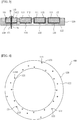
- the rotating electrical machine 1 comprises a stator 2 and a rotor 3.
- the stator 2 is provided to the inner peripheral surface of a frame 4 so that it is positioned opposite the rotor 3 in the diameter direction.
- the stator 2 comprises a laminated core body 5, a bobbin 6 through which the laminated core body 5 is inserted, and windings 7 that is wound around the bobbin 6.
- the bobbin 6 is made of an insulating material such as resin in order to electrically insulate the laminated core body 5 and the windings 7.
- a circular wire connecting substrate 100 that connects an end portion 7a of the windings 7 using a predetermined connection pattern is provided to a side opposite to a load side (left side in FIG 1 ) of the bobbin 6.
- the winding end portion 7a is fixed to the wire connecting substrate 100 by solder H.
- the wire connecting substrate 100 is covered by a resin 15.
- the rotor 3 comprises a yoke 8 and a permanent magnet 9.
- the rotor 3 is provided on the outer peripheral surface of a rotating shaft 10.
- the rotating shaft 10 is rotatably supported by bearings 12 on the load side and bearings 14 on the side opposite to the load side.
- the outer ring of the bearings 12 on the load side is fit to a bracket 11 on the load side.
- the outer ring of the bearings 14 on the side opposite to the load side is fit to a bracket 13 on the side opposite to the load side.
- the rotating electrical machine 1 is a three-phase AC electrical motor.
- the rotating electrical machine 1 comprises the stator 2 to which 12 of the windings 7 are assembled in a circular shape.
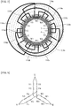
- the wire connecting substrate 100 comprises a plurality of circular-arc shaped conductive members 110 and a circular-shaped insulating member 120, concentrically disposed.
- Each of the conductive members 110 is connected to the winding end portion 7a of the stator 2.
- the insulating member 120 covers the plurality of conductive members 110. While details will be described later, the plurality of conductive members 110 is formed by shaping into a spiral shape a rectangular wire 101 (a single wire rod; refer to FIG. 7 ) to be covered, and then dividing (creating absences within) this rectangular wire 101 to be covered at predetermined locations.
- the conductive member 110 is configured so that the conductive wire rod divided by absent portions is disposed in layers in the radial direction. Note that the absent portions actually occur in the insulating member 120 as well when the rectangular wire 101 to be covered is divided, but these absent portions are not shown in FIG. 2 to prevent complexities in the illustration.
- each of the conductive members 110 is substantially concentrically disposed to form four layers in the radial direction.
- Six conductive members 110a to 110f disposed on the innermost peripheral side are conductive members for crossover.
- the conductive members 110a to 110f are disposed at substantially equal spacing along the circumferential direction of a concentric circle R1.
- Two conductive members 110n and 110n disposed on the outer peripheral side of the conductive members 110a to 110f are conductive members for neutral points.
- the conductive members 110n and 110n are disposed along the circumferential direction of a concentric circle R2.
- Conductive members 110u and 110v disposed further on the outer peripheral side of the conductive members 110n and 110n are conductive members for a U phase and a V phase, respectively.
- the conductive members 110u and 110v are disposed somewhat along the circumferential direction of a concentric circle R3.
- a conductive member 110w disposed on the outermost peripheral side is a conductive member for a W phase.
- the conductive member 110w is disposed along the circumferential direction of a concentric circle R4.
- each of the conductive members is suitably referred to as crossover conductive members 110a to 110f, neutral point conductive members 110n, U-phase conductive member 110u, V-phase conductive member 110v, and W-phase conductive member 110w.
- the U-phase conductive member 110u comprises a linear portion 110uc that linearly extends in the direction of a tangent line X of the inner peripheral portion 110ui.
- the linear portion 110uc is integrally provided between the two circular-arc shaped portions of the inner peripheral portion 110ui and the outer peripheral portion 110uo, which are concentrically disposed but differ in radius of curvature.
- the V-phase conductive member 110v comprises a linear portion 110vc that linearly extends in the direction of a tangent line Y of the inner peripheral portion 110vi.
- the linear portion 110vc is integrally provided between the two circular-arc shaped portions of the inner peripheral portion 110vi and the outer peripheral portion 110vo, which are concentrically disposed but differ in radius of curvature.
- the cross-sectional shape of the conductive member 110 (the rectangular wire 101 to be covered) is substantially square.
- the conductive member 110 comprises a conductive material 111 and a covering material 112 that covers the conductive material 111.
- a through-hole 113 through which the winding end portion 7a is inserted in the axial direction of the rotating shaft 10 is provided as a through portion at the substantial center position in the width direction of both longitudinal end portions of each of the conductive members 110.
- the winding end portion 7a that is inserted through this through-hole 113 is fixed by the solder H to the surface of the connection side (the side opposite to the load side) of the conductive member 110.
- the covering material 112 is peeled away from the circumference of the through-hole 113 of the conductive member 110, and the solder H is provided to this peeled-away section.
- the through portion used may be something other than a hole, such as a notch.
- the insulating member 120 is a circular member formed by insert molding using a resin material, for example.
- the insulating member 120 fixes each of the conductive members 110 to a predetermined location on a common plane (not shown) that is substantially orthogonal to the axial direction of the rotating shaft 10. Further, the insulating member 120 maintains the insulation between each of the conductive members 110. As shown in FIG. 2 and FIG. 3 , the insulating member 120 exposes at least the surface of the conductive member 110 that is on the connection side while covering all other surfaces. Note that, as shown in FIG. 3 , each of the conductive members 110 is actually disposed so that a predetermined space is created in the radial direction by the insulating member 120. Nevertheless, this space is not shown in FIG. 2 .
- a tapered hole 121 is provided to the location of the insulating member 120 corresponding to the through-hole 113 of the conductive member 110.
- This tapered hole 121 is provided to a surface 122 on the side opposite the connection side (the load side) of the insulating member 120.
- the diameter of the tapered hole 121 gradually decreases from the surface 122 toward the through-hole 113 of the conductive member 110.
- the winding end portion 7a of the stator 5 is inserted through the through-hole 113 of the conductive member 110 from the stator 5 side via this tapered hole 121.
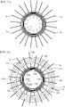
- connection pattern of the wire connecting substrate 100 will be described using FIG. 5 and FIG. 6 .
- the reference numerals of each of the windings shown in FIG. 5 and FIG. 6 have a corresponding relationship.
- the windings 7 corresponding to U1 is called windings U1.
- the wire connecting substrate 100 connects the winding end portion 7a of the stator 2 using a connection pattern having two star connection systems.
- the star connection connects each of the three phases at a neutral point of one end.
- the end portions 7a of one side of windings U1 and windings U2, which form a system on one side of the U-phase are connected by the crossover conductive member 110c.
- the end portions 7a of one side of windings U3 and windings U4, which form a system of the other side of the U-phase, are connected by the crossover conductive member 110f.
- the end portions 7a of one side of windings V1 and windings V2, which form a system of one side of the V-phase, are connected by the crossover conductive member 110e.
- the end portions 7a of one side of windings V3 and windings V4, which form a system of the other side of the V-phase, are connected by the crossover conductive member 110b.
- the end portions 7a of one side of windings W1 and windings W2, which form a system of one side of the W-phase are connected by the crossover conductive member 110d.
- the end portions 7a of one side of windings W3 and windings W4, which form a system of the other side of the W-phase are connected by the crossover conductive member 110a.
- the end portions 7a of the other side of the windings U2, V2, and W2 are connected by the neutral point conductive member 110n.
- the end portions 7a of the other side of the windings U4, V4, and W4 are connected by the neutral point conductive member 110n.
- the end portion 7a of the other side of the windings U1 and the end portion 7a of the other side of the windings U3 are connected to the U-phase via the U-phase conductive member 110u.
- the end portion 7a of the other side of the windings V 1 and the end portion 7a of the other side of the windings V3 are connected to the V-phase via the V-phase conductive member 110v.
- the end portion 7a of the other side of the windings W1 and the end portion 7a of the other side of the windings W3 are connected to the W-phase via the W-phase conductive member 110w.
- the manufacturing methods of the wire connecting substrate 100 and the rotating electrical machine 1 will be described using FIG. 7 to FIG. 14 .
- the single rectangular wire 101 to be covered is formed into a spiral shape.
- the spiral shape may be a simple spiral shape wherein the radius of curvature continually changes. Nevertheless, a spiral shape having the linear portions 101a to 101c is preferred.
- the linear portions 101a to 101c are sections that linearly extend in a tangent line direction of the circular-arc shaped sections, along the concentric circle R on the inner peripheral side.
- the spiral shape having the linear portions 101a to 101c it is possible to dispose the sections of the rectangular wire 101 to be covered other than the linear portions 101a to 101c on the concentric circles R1 to R4. As a result, the subsequent hole punching work for the through-hole 113 and the connection work with the winding end portion 7a can be easily performed.
- the rectangular wire 101 to be covered comprises the conductive material 111 and the covering material 112, forming a substantially square cross-sectional shape.
- the linear portions 101b and 101c shown in FIG. 7 respectively correspond to the linear portions 110vc and 110uc shown in FIG. 2 . Note that this step corresponds to the first step described in the claims.
- the rectangular wire 101 to be covered is wound to form four layers in the radial direction
- the number of windings is not limited thereto. That is, a suitable number of windings is set in accordance with the connection pattern, etc., of the wire connecting substrate 100.
- the rectangular wire 101 to be covered that was thus formed into a spiral shape is fixed to metal die, and resin material is insert-molded.
- the rectangular wire 101 to be covered is covered with insulating material.
- the rectangular wire 101 to be covered is covered so that at least the surface on the connection side of the rectangular wire 101 to be covered is exposed.
- the insulating member 120 is formed, as shown in FIG. 8 . Note that this step corresponds to the second step described in the claims.
- the rectangular wire 101 to be covered that was thus covered with insulating material is divided at predetermined circumferential locations to form the connection pattern shown in FIG. 5 .
- an absent portion S (shown by the dashed line in FIG. 9 ) having a predetermined length is formed in the rectangular wire 101 to be covered using a drill or punch press, for example.
- both longitudinal end portions of each of the conductive members 110 formed by the division by the absent portion S can serve as connection locations for the rectangular wire 101 to be covered and the winding end portion 7a.
- Each of the conductive members 110 formed by division comprises a concave curved surface 114 corresponding to the shape of the drill or punch press on both end portions in the circumferential direction.
- the absent portion S does not necessarily need to be formed at a predetermined length as in this embodiment.
- the absent portion S may form a simple round hole shape or a short square hole shape.
- the division process may be performed using a tool other than a drill or punch press.
- the formed end surface shape of each of the conductive members 110 may be flat rather than curved. That is, as long as the rectangular wire 101 to be covered is divided so that the insulation of each of the conductive members 110 is maintainable, there is no limit to the shape or length of the absent portion S.
- the through-hole 113 through which the winding end portion 7a is inserted in the axial direction of the rotating shaft 10 is formed in each of the conductive members 110 using a drill, etc.
- the through-hole 113 is provided to the substantially central position in the width direction of both longitudinal end portions of each of the conductive members 110.
- the covering material 112 around the circumference of the through-hole 113 of each of the conductive members 110 is peeled away using a tool such as sand paper or a knife.
- the tapered hole 121 is provided to a location corresponding to the through-hole 113 of the surface 122 on the opposite side of the connection side of the insulating member 120 using a drill, etc. (refer to FIG. 3 and FIG. 4 ). With the above steps, the wire connecting substrate 100 is thus manufactured.
- each of the winding end portions 7a pulled out from the stator 2 is inserted through the through-hole 113 of the corresponding conductive member 110 via the tapered hole 121 provided to the insulating member 120.
- the wire connecting substrate 100 is fixed to the insulator (not shown) of the stator 2 using adhesive or the like.
- the unnecessary section of the winding end portion 7a is cut off to form a length at which the winding end portion 7a slightly protrudes from the surface on the connection side of each of the conductive members 110.
- soldering is performed to fix each of the winding end portions 7a to each of the conductive members 110 by the solder H.
- a portion of the process refers to steps that require manual work, such as fixing the rectangular wire 101 to be covered to the metal die when forming the insulating member 120.
- step ( FIG. 10 ) of providing the through-hole 113 to the conductive member 110, and the step ( FIG. 12 ) of inserting the winding end portion 7a through the through-hole 113 via the tapered hole 121 correspond to the fourth step described in the claims.
- each of the conductive members 110 of the wire connecting substrate 100 comprises a through-hole 113. Then, the winding end portion 7a of the stator 2 is directly connected to the conductive member 110 by inserting the winding end portion 7a through this through-hole 113 in the axial direction of the rotating shaft 10. With this arrangement, the terminal member for connecting the winding end portion 7a and the conductive member 110 is no longer required. As a result, compared to a configuration in which the terminal member is provided so as to protrude from the insulating member 120 toward the outer peripheral side in the diameter direction, it is possible to decrease the dimension in the diameter direction of the wire connecting substrate 100.
- the terminal member in a case where the terminal member protrudes toward the outer peripheral side of the insulating member 120, the terminal member must be routed around in the axial direction of the rotating shaft 10 to prevent the terminal member of the conductive member 110 on the inner peripheral side from interfering with the conductive member 110 on the outer peripheral side.
- the conductive member 110 of each phase needs to be arranged so that it shifts in the axial direction of the rotating shaft 10. This then causes an increase in the axial dimension of the wire connecting substrate 100.
- the winding end portion 7a of the stator 2 is inserted in the axial direction of the rotating shaft 10 and connected to each of the conductive members 110.
- the terminal member no longer needs to be routed around in the axial direction of the rotating shaft 10, and the conductive member 110 no longer needs to be shifted in position in the axial direction of the rotating shaft 10 for each phase. Accordingly, it is possible to decrease the axial dimension of the wire connecting substrate 100. Accordingly, miniaturization of the wire connecting substrate 100 is thus achieved in the diameter direction and the axial direction. As a result, miniaturization of the rotating electrical machine 1 is achieved.
- the conductive members 110v and 100u respectively comprise the linear portions 110vc and 110uc that linearly extend in the tangent line direction of the concentric circle R on the inner peripheral side.
- the linear portions 110vc and 110uc thus provided, it is possible to form the plurality of concentrically arranged conductive members 110 with the single rectangular wire 101 to be covered, which is wound in layers in the radial direction, divided into parts.
- This achievement of forming the conductive member 110 using a single wire rod significantly suppresses waste in material compared to a case where the conductive member 110 is formed by stamping the metal member. Thus, a reduction in cost is achieved.
- the plurality of conductive members 110 is formed using a single wire rod, division of the rectangular wire 101 to be covered that is formed into a simple spiral shape without any linear portions is also conceivable. Nevertheless, in such a case, the radius of curvature of the formed conductive member 110 continuously changes. As a result, the level of difficulty of the work of punching the through-hole 113 into the conductive member 110, as well as the connection work of inserting and connecting the winding end portion 7a of the stator 2 though the through-hole 113 increases. Conversely, according to this embodiment, the linear portions 110vc and 110uc are provided to the conductive members 110v and 110u.
- the rectangular wire 101 to be covered is formed into a spiral shape comprising the linear portions 110vc and 110uc.
- this arrangement it is possible to achieve a uniform radius of curvature of the rectangular wire 101 to be covered in regions other than the linear portions 110vc and 110uc, and concentrically dispose the rectangular wire 101 to be covered.
- simplification of the hole punching work and connection work is achieved. Further, automation of this work is also possible.
- the tapered hole 121 is provided to a location corresponding to the through-hole 113 provided to the conductive member 110 on the side opposite the connection side of the insulating member 120.
- This tapered hole 121 makes it possible to introduce the winding end portion 7a of the stator 2 through the through-hole 113. Accordingly, connection work is further simplified, facilitating automation thereof.
- the conductive member 110 comprises the convex curved surface 114 on both end portions in the circumferential direction.
- Such the conductive member 110 can be formed by dividing the rectangular wire 101 to be covered, which is wound in layers at predetermined locations, using a drill or punch press, which is a general-purpose tool. As a result, it is possible to readily form the conductive member 110 at a low price, without use of a special tool.
- the rectangular wire 101 to be covered which has a square cross-sectional shape, is used for the conductive member 110.
- the process of providing the through-hole 113 through which the winding end portion 7a is inserted to the conductive member 110 and the process of division at predetermined locations are easier to perform.
- the workability of the conductive member 110 is improved.
- soldering may be performed on a flat surface using the rectangular wire 101 to be covered. As a result, an improvement in workability is achieved.
- the radial spacing between the conductive members 110 for maintaining insulation needs to be a certain size or greater.
- Use of the rectangular wire 101 to be covered as in the embodiment makes it possible to minimize this spacing to the extent possible and further minimize the dimension of the wire connecting substrate 100 in the diameter direction.
- the plurality of conductive members 110 of the wire connecting substrate 100 is configured so that the rectangular wire 101 to be covered, which is divided by the absent portion S, is disposed in layers in the radial direction. Then, the plurality of conductive members 110 is disposed on the same plane, which is substantially orthogonal to the rotating shaft direction.
- the wire connecting substrate 100 is manufactured by dividing the rectangular wire 101 to be covered, which is a single conductive wire rod formed into a spiral shape, at predetermined circumferential positions.
- the plurality of conductive members 110 formed by this division process can be disposed on a common plane which is substantially orthogonal to the rotating shaft direction. With this arrangement, it is possible to decrease the axial dimension of the wire connecting substrate 100 to the extent possible. As a result, miniaturization of the rotating electrical machine 1 is achieved. Further, the achievement of forming the conductive member 110 using a single wire rod significantly suppresses waste in material compared to a case where the conductive member 110 is formed by stamping the metal member, etc. Accordingly, a reduction in cost is achieved.
- connection pattern has two star connection systems
- present disclosure is not limited thereto. That is, the present disclosure may be applied to various connection patterns, such as delta connection or V-shaped connection, by suitably changing the number of windings, the division locations, and the connection locations of the rectangular wire 101 to be covered.
- the rotating electrical machine 1 is a three-phase AC electrical motor having 12 of the windings 7.
- the number of the windings 7 may be suitably changed.
- the present disclosure may also be applied to an electrical motor other than a three-phase AC electrical motor, such as a single-phase AC electrical motor or DC electrical motor. That is, the type of electrical motor is not limited. As long as the end portion of the windings of the stator is connected using a predetermined connection pattern, the present disclosure may be applied to various electrical motors.
- a rectangular wire that is without the covering material 112 may be used for the conductive member 110.
- a rectangular wire is not necessarily required; use of a wire (such as a round wire) having a cross-sectional shape other than a square may be employed.
- the rectangular wire 101 to be covered is formed into a spiral shape having linear portions 101a to 101c
- the present disclosure is not limited thereto.
- the rectangular wire 101 to be covered may be formed into a simple spiral shape without any linear portions, wherein the radius of curvature continually changes.
- the conductive member is formed by dividing this formed object.
- miniaturization of the wire connecting substrate 100 is achieved.
- the plurality of circular-arc shaped conductive members 110 is formed by dividing the single wire rod at predetermined locations, the present disclosure is not limited thereto.
- circular-arc shaped or circular-shaped conductive members achieved by stamping the metal member may be concentrically disposed, and a through-hole through which the end portion of the windings is inserted in the axial direction of the rotating shaft 10 may be provided to thereto.
- miniaturization of the wire connecting substrate 100 is achieved.
- the rotating electrical machine 1 is an inner rotor type comprising the rotor 3 on the inside of the stator 2
- present disclosure is also applicable to a rotating electrical machine of an outer rotor type comprising the rotor 3 on the outside of the stator 2.
- present disclosure is also applicable to a case where the rotating electrical machine 1 is a generator.
Landscapes
- Engineering & Computer Science (AREA)
- Power Engineering (AREA)
- Insulation, Fastening Of Motor, Generator Windings (AREA)
- Manufacture Of Motors, Generators (AREA)
- Windings For Motors And Generators (AREA)
Applications Claiming Priority (3)
| Application Number | Priority Date | Filing Date | Title |
|---|---|---|---|
| JP2011172127A JP5713836B2 (ja) | 2011-08-05 | 2011-08-05 | 回転電機及び回転電機の結線基板 |
| JP2011172129A JP5348199B2 (ja) | 2011-08-05 | 2011-08-05 | 回転電機の製造方法及び回転電機の結線基板の製造方法 |
| JP2011172128A JP5585943B2 (ja) | 2011-08-05 | 2011-08-05 | 回転電機及び回転電機の結線基板 |
Publications (1)
| Publication Number | Publication Date |
|---|---|
| EP2555390A2 true EP2555390A2 (de) | 2013-02-06 |
Family
ID=45607627
Family Applications (1)
| Application Number | Title | Priority Date | Filing Date |
|---|---|---|---|
| EP12154392A Withdrawn EP2555390A2 (de) | 2011-08-05 | 2012-02-08 | Rotierende elektrische Maschine mit Drahtverbindungssubstrat |
Country Status (5)
| Country | Link |
|---|---|
| US (1) | US20130033135A1 (de) |
| EP (1) | EP2555390A2 (de) |
| CN (2) | CN202737617U (de) |
| BR (1) | BR102012003666A2 (de) |
| IN (1) | IN2012DE00428A (de) |
Cited By (1)
| Publication number | Priority date | Publication date | Assignee | Title |
|---|---|---|---|---|
| CN114284796A (zh) * | 2021-12-27 | 2022-04-05 | 上海精测半导体技术有限公司 | 一种上电装置及真空处理装置 |
Families Citing this family (3)
| Publication number | Priority date | Publication date | Assignee | Title |
|---|---|---|---|---|
| EP3627671A1 (de) | 2018-09-21 | 2020-03-25 | Siemens Aktiengesellschaft | Verfahren zur herstellung einer wickelkopfanordnung für eine elektrische rotierende maschine |
| JP7264717B2 (ja) * | 2019-05-15 | 2023-04-25 | ファナック株式会社 | ステータコアの端面に固定されるハウジングを備える電動機 |
| CN112953073B (zh) * | 2021-01-28 | 2021-10-08 | 浙江方正电机股份有限公司 | 一种扁铜线油冷电机定子的端部集成模块及定子 |
Citations (1)
| Publication number | Priority date | Publication date | Assignee | Title |
|---|---|---|---|---|
| JP2006158199A (ja) | 2006-03-16 | 2006-06-15 | Yaskawa Electric Corp | 回転電機の固定子 |
Family Cites Families (10)
| Publication number | Priority date | Publication date | Assignee | Title |
|---|---|---|---|---|
| GB0109179D0 (en) * | 2001-04-12 | 2001-05-30 | Alstom | Improvements relating to rotary electrical machines |
| DE102004003146B4 (de) * | 2003-01-22 | 2023-08-24 | Aisan Kogyo Kabushiki Kaisha | Motor, Kraftstoffpumpe, Kommutator und Verfahren zur Herstellung eines Kommutators |
| JP2006204029A (ja) * | 2005-01-21 | 2006-08-03 | Sumitomo Electric Ind Ltd | 線材と被接続材との接続固定構造 |
| JP2006246594A (ja) * | 2005-03-02 | 2006-09-14 | Toyota Motor Corp | 回転電機の配線部材 |
| JP2008061305A (ja) * | 2006-08-29 | 2008-03-13 | Aisin Seiki Co Ltd | 給電装置および回転電機 |
| JP2008125328A (ja) * | 2006-11-15 | 2008-05-29 | Aisin Aw Co Ltd | 3相モータ用のステータ |
| US7723879B2 (en) * | 2006-12-12 | 2010-05-25 | Nidec Corporation | Motor having multiple busbar plates and wire for the same |
| US7936100B2 (en) * | 2007-04-02 | 2011-05-03 | Hitachi, Ltd. | Stator for rotating machine and rotating machine using the same |
| JP5140389B2 (ja) * | 2007-11-22 | 2013-02-06 | 株式会社日立製作所 | 回転電機用の固定子、及びこれを用いた回転電機 |
| JP4494457B2 (ja) * | 2007-12-12 | 2010-06-30 | トヨタ自動車株式会社 | 回転電機の集中配電部材 |
-
2012
- 2012-02-08 EP EP12154392A patent/EP2555390A2/de not_active Withdrawn
- 2012-02-09 US US13/369,299 patent/US20130033135A1/en not_active Abandoned
- 2012-02-15 IN IN428DE2012 patent/IN2012DE00428A/en unknown
- 2012-02-16 CN CN201220050915.XU patent/CN202737617U/zh not_active Expired - Fee Related
- 2012-02-16 CN CN201210035591.7A patent/CN102916515B/zh active Active
- 2012-02-17 BR BR102012003666-5A patent/BR102012003666A2/pt not_active IP Right Cessation
Patent Citations (1)
| Publication number | Priority date | Publication date | Assignee | Title |
|---|---|---|---|---|
| JP2006158199A (ja) | 2006-03-16 | 2006-06-15 | Yaskawa Electric Corp | 回転電機の固定子 |
Cited By (1)
| Publication number | Priority date | Publication date | Assignee | Title |
|---|---|---|---|---|
| CN114284796A (zh) * | 2021-12-27 | 2022-04-05 | 上海精测半导体技术有限公司 | 一种上电装置及真空处理装置 |
Also Published As
| Publication number | Publication date |
|---|---|
| US20130033135A1 (en) | 2013-02-07 |
| CN202737617U (zh) | 2013-02-13 |
| CN102916515A (zh) | 2013-02-06 |
| BR102012003666A2 (pt) | 2013-10-29 |
| CN102916515B (zh) | 2015-04-22 |
| IN2012DE00428A (de) | 2015-06-05 |
Similar Documents
| Publication | Publication Date | Title |
|---|---|---|
| JP5740930B2 (ja) | ステータ及びモータ | |
| JP5740931B2 (ja) | 分割ステータ、及びモータ | |
| JP5703604B2 (ja) | バスバーユニット及びモータ | |
| EP2063516B1 (de) | Stator für Drehmaschine und Drehmaschine damit | |
| EP3051671A1 (de) | Busschieneneinheit, verfahren zur herstellung einer busschieneneinheit und bürstenloser motor | |
| JP2016127798A (ja) | モータおよびモータの製造方法 | |
| EP3166209A1 (de) | Stator für elektrisches rotationsmaschine | |
| EP3176912A1 (de) | Stator und drehmaschine | |
| JP2011182603A (ja) | ロータ、ロータの製造方法及びモータ | |
| CN1871759B (zh) | 短路部件、整流子及短路部件的制造方法 | |
| JP2018133934A (ja) | ブラシレスモータ | |
| EP2555390A2 (de) | Rotierende elektrische Maschine mit Drahtverbindungssubstrat | |
| WO2020174817A1 (ja) | 回転電機のステータ、回転電機、回転電機のステータの製造方法、および、回転電機の製造方法 | |
| JP5290718B2 (ja) | 電機子の製造方法 | |
| JP6288002B2 (ja) | 回転電機ステータの製造方法及び回転電機用カセットコイル | |
| JP5585943B2 (ja) | 回転電機及び回転電機の結線基板 | |
| JP2010183660A (ja) | ステータ、ブラシレスモータ、ステータの製造方法、及び、ブラシレスモータの製造方法 | |
| JP6080964B2 (ja) | 回転電機の固定子 | |
| EP4175127A1 (de) | Motor | |
| JP2008022626A (ja) | 回転機 | |
| JP5713836B2 (ja) | 回転電機及び回転電機の結線基板 | |
| JP5348199B2 (ja) | 回転電機の製造方法及び回転電機の結線基板の製造方法 | |
| CN211701655U (zh) | 马达 | |
| JP2006174547A (ja) | 回転電機の固定子 | |
| JP5858302B2 (ja) | 回転電機及び回転電機の結線基板 |
Legal Events
| Date | Code | Title | Description |
|---|---|---|---|
| PUAI | Public reference made under article 153(3) epc to a published international application that has entered the european phase |
Free format text: ORIGINAL CODE: 0009012 |
|
| AK | Designated contracting states |
Kind code of ref document: A2 Designated state(s): AL AT BE BG CH CY CZ DE DK EE ES FI FR GB GR HR HU IE IS IT LI LT LU LV MC MK MT NL NO PL PT RO RS SE SI SK SM TR |
|
| AX | Request for extension of the european patent |
Extension state: BA ME |
|
| STAA | Information on the status of an ep patent application or granted ep patent |
Free format text: STATUS: THE APPLICATION HAS BEEN WITHDRAWN |
|
| 18W | Application withdrawn |
Effective date: 20160120 |