EP2555190B1 - Verfahren, Vorrichtung und Computerprogramm zur Rauschunterdrückung - Google Patents
Verfahren, Vorrichtung und Computerprogramm zur Rauschunterdrückung Download PDFInfo
- Publication number
- EP2555190B1 EP2555190B1 EP12190386.8A EP12190386A EP2555190B1 EP 2555190 B1 EP2555190 B1 EP 2555190B1 EP 12190386 A EP12190386 A EP 12190386A EP 2555190 B1 EP2555190 B1 EP 2555190B1
- Authority
- EP
- European Patent Office
- Prior art keywords
- frequency
- spectral
- domain signals
- noise
- supplied
- Prior art date
- Legal status (The legal status is an assumption and is not a legal conclusion. Google has not performed a legal analysis and makes no representation as to the accuracy of the status listed.)
- Ceased
Links
- 238000000034 method Methods 0.000 title claims description 25
- 238000004590 computer program Methods 0.000 title claims description 7
- 230000003595 spectral effect Effects 0.000 claims description 108
- 230000008569 process Effects 0.000 claims description 7
- 230000005236 sound signal Effects 0.000 claims description 7
- 230000001131 transforming effect Effects 0.000 claims 2
- 238000001228 spectrum Methods 0.000 description 72
- 239000003607 modifier Substances 0.000 description 54
- 230000015654 memory Effects 0.000 description 50
- 238000010586 diagram Methods 0.000 description 38
- 230000006870 function Effects 0.000 description 21
- 230000004044 response Effects 0.000 description 10
- 230000010354 integration Effects 0.000 description 9
- 238000012886 linear function Methods 0.000 description 9
- 230000001629 suppression Effects 0.000 description 8
- 238000012937 correction Methods 0.000 description 6
- 238000012545 processing Methods 0.000 description 5
- 238000012546 transfer Methods 0.000 description 4
- 238000006243 chemical reaction Methods 0.000 description 3
- 230000015556 catabolic process Effects 0.000 description 2
- 238000006731 degradation reaction Methods 0.000 description 2
- 230000000694 effects Effects 0.000 description 2
- 238000011156 evaluation Methods 0.000 description 2
- 238000005070 sampling Methods 0.000 description 2
- 230000009466 transformation Effects 0.000 description 2
- 101000582320 Homo sapiens Neurogenic differentiation factor 6 Proteins 0.000 description 1
- 102100030589 Neurogenic differentiation factor 6 Human genes 0.000 description 1
- 238000004364 calculation method Methods 0.000 description 1
- 230000008859 change Effects 0.000 description 1
- 230000006866 deterioration Effects 0.000 description 1
- 239000000284 extract Substances 0.000 description 1
- 238000001914 filtration Methods 0.000 description 1
- 230000001788 irregular Effects 0.000 description 1
- 238000012892 rational function Methods 0.000 description 1
- 230000035945 sensitivity Effects 0.000 description 1
- 239000000758 substrate Substances 0.000 description 1
Images


Classifications
-
- G—PHYSICS
- G10—MUSICAL INSTRUMENTS; ACOUSTICS
- G10L—SPEECH ANALYSIS TECHNIQUES OR SPEECH SYNTHESIS; SPEECH RECOGNITION; SPEECH OR VOICE PROCESSING TECHNIQUES; SPEECH OR AUDIO CODING OR DECODING
- G10L21/00—Speech or voice signal processing techniques to produce another audible or non-audible signal, e.g. visual or tactile, in order to modify its quality or its intelligibility
- G10L21/02—Speech enhancement, e.g. noise reduction or echo cancellation
- G10L21/0208—Noise filtering
-
- G—PHYSICS
- G10—MUSICAL INSTRUMENTS; ACOUSTICS
- G10L—SPEECH ANALYSIS TECHNIQUES OR SPEECH SYNTHESIS; SPEECH RECOGNITION; SPEECH OR VOICE PROCESSING TECHNIQUES; SPEECH OR AUDIO CODING OR DECODING
- G10L19/00—Speech or audio signals analysis-synthesis techniques for redundancy reduction, e.g. in vocoders; Coding or decoding of speech or audio signals, using source filter models or psychoacoustic analysis
- G10L19/02—Speech or audio signals analysis-synthesis techniques for redundancy reduction, e.g. in vocoders; Coding or decoding of speech or audio signals, using source filter models or psychoacoustic analysis using spectral analysis, e.g. transform vocoders or subband vocoders
- G10L19/0204—Speech or audio signals analysis-synthesis techniques for redundancy reduction, e.g. in vocoders; Coding or decoding of speech or audio signals, using source filter models or psychoacoustic analysis using spectral analysis, e.g. transform vocoders or subband vocoders using subband decomposition
-
- G—PHYSICS
- G10—MUSICAL INSTRUMENTS; ACOUSTICS
- G10L—SPEECH ANALYSIS TECHNIQUES OR SPEECH SYNTHESIS; SPEECH RECOGNITION; SPEECH OR VOICE PROCESSING TECHNIQUES; SPEECH OR AUDIO CODING OR DECODING
- G10L21/00—Speech or voice signal processing techniques to produce another audible or non-audible signal, e.g. visual or tactile, in order to modify its quality or its intelligibility
- G10L21/02—Speech enhancement, e.g. noise reduction or echo cancellation
- G10L21/0208—Noise filtering
- G10L21/0216—Noise filtering characterised by the method used for estimating noise
Definitions
- the present invention relates to a method and apparatus for suppressing noise to reduce the noise superimposed on a desired audio signal as well as to a computer program for use in signal processing of noise suppression.
- a noise suppressor (noise suppressing system) is a system for suppressing noise superimposed on a desired audio signal, and typically estimates the power spectrum of the noise component using the input signal that was converted into frequency domain, and subtracts this estimated power spectrum from the input signal to thereby suppress the noise mixed in the desired audio signal. When the power spectrum of the noise component is continuously estimated, it is possible to deal with the suppression of irregular noise.
- a conventional noise suppressor is disclosed in patent document 1 (Japanese Patent Application Laid-open 204175/2002 ), for example.
- a digital signal that has been obtained by analog-to-digital (AD) conversion of an output signal from a microphone that corrects speech waves is supplied as an input signal to a noise suppressor.
- AD analog-to-digital
- a high-pass filter is disposed between AD conversion and a noise suppressor in order to suppress a low-frequency component that is added during speech collection with a microphone or during AD conversion.
- Patent document 2 United State Patent No. 5,659,622 ).
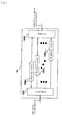
- FIG. 1 shows a configuration in which a high-pass filter of patent document 2 is applied to a noise suppressor of patent document 1.
- a noisy speech signal (a signal that contains a desired speech signal and noise) as a sequence of sample values.
- the noisy speech signal samples are supplied to high-pass filter 17 where the low-pass component is suppressed, and then are supplied to frame divider 1. Suppression of the low-pass component is an essential process in order to maintain the linearity of the input noisy speech and to present high enough signal processing performance.
- Frame divider 1 divides the noisy speech signal samples into frames of a specified number of samples and transmits them to windowing processor 2.
- Windowing processor 2 multiplies the divided frame of noisy speech samples by a window function and transmits the result to Fourier transformer 3.
- Fourier transformer 3 performs a Fourier transform on the windowed, noisy speech samples to divide the samples into a plurality of frequency components and multiplex the amplitude values and supplies them to estimated noise calculator 52, spectral gain generator 82 and multiplex multiplier 16. The phases are transmitted to invert Fourier transformer 9.
- Estimated noise calculator 52 estimates the noise for each of the supplied multiple frequency components and transmits them to spectral gain generator 82.
- noise estimation there is a method of estimating the noise component by weighting the noisy speech based on the past signal-to-noise ratio, the detail being described in patent document 1.
- Spectral gain generator 82 generates individual spectral gains for multiple frequency components, in order to produce enhanced speech with noise suppressed by multiplying the noisy speech by the coefficients.
- spectral gains the least mean square short period spectrum amplitude method in which the mean square power of enhanced speech is minimized has been widely used. Details are described in patent document 1.
- the spectral gains generated for individual frequencies are supplied to multiplex multiplier 16.
- Multiplex multiplier 16 multiplies the noisy speech supplied from Fourier transformer 3 and the spectral gain supplied from spectral gain generator 82 for every frequency, and transmits the products as the amplitudes of the enhanced speech to inverse Fourier transformer 9.
- Inverse Fourier transformer 9 performs inverse Fourier transformation making use of the enhanced speech amplitudes supplied from multiplex multiplier 16 and the phases of the noisy speech supplied from Fourier transformer 3 and supplies the result as enhanced speech signal samples to frame synthesizer 10.
- This frame synthesizer 10 synthesizes output speech samples of the current frame using the enhanced speech samples of the neighboring frame and outputs the result to output terminal 12.
- High-pass filter 17 suppresses the frequency components in the vicinity of the direct current, and usually permits components having frequencies equal to or greater than 100 Hz to 120 Hz to pass through as they are without suppression.
- high-pass filter 17 can be configured of either a finite impulse response (FIR) type filter or an infinite impulse response (IIR) type filter, usually the latter is used because a sharp passband end characteristic is needed.
- FIR finite impulse response
- IIR infinite impulse response
- the transfer function of an IIR type filter is represented by a rational function and the sensitivity of the denominator coefficient is markedly high. Accordingly, when high-pass filter 17 is realized by finite word length operations, it is necessary to use frequent double precision operations in order to achieve high enough precision. So there has been the problem that the amount of operations becomes great. In contrast, if high-pass filter 17 is omitted in order to reduce the amount of operations, it is difficult to maintain the linearity of the input signal, hence it is impossible to achieve high-quality noise suppression.
- estimated noise calculator 52 noise is estimated for all the frequency components supplied from Fourier transformer 3, and in spectral gain generator 82, spectral gains corresponding to these are determined. Therefore, if the block length (frame length) for the Fourier transform is made longer in order to improve frequency resolution, the number of samples constituting each block becomes greater, resulting in the problem that the amount of operations increases.
- Non patent document KATO M ET AL "A family of 3GPP-standard noise suppressors for the AMR CODEC and the evaluation results", ICASSP, IEEE INTERNATIONAL CONFERENCE ON ACOUSTICS, SPEECH AND SIGNAL PROCESSING - PROCEEDINGS 2003 INSTITUTE OF ELECTRICAL AND ELECTRONICS ENGINEERS INC. US, vol. 1, 6 April 2003, pages 916-919, Hongkong , discloses a noise suppressing method for suppressing noise for a 3GPP-standard type codec.
- the object of the present invention is to provide a noise suppressing method and apparatus capable of achieving high-quality noise suppression using a lower amount of operations.
- a noise suppressing method is provided according to claim 1.
- the method, apparatus and computer program for suppressing noise of the present invention are defined by execution of suppression of low-pass components for the signal after the Fourier transform. More specifically, the invention is defined by inclusion of an amplitude modifier for suppressing low-pass components for the amplitudes of the Fourier transformed output and a phase modifier for performing phase correction corresponding to amplitude deformation of low-pass components for the phase of the Fourier transformed output.
- the invention is defined in that noise estimation and generation of spectral gains are performed for multiple frequency components. More specifically, the invention is defined by inclusion of a band integrator for integrating part of multiple frequency components.
- noise estimation and generation of noise coefficients are performed for a lower number of frequency components than the number of samples that constitute each block of Fourier transform, so that it is possible to reduce the amount of operations.
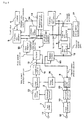
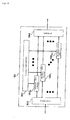
- FIG. 2 is a block diagram showing the first embodiment of the present invention.
- FIG. 2 The configuration shown in FIG. 2 and the conventional configuration shown in FIG. 1 are the same except for high-pass filter 17, amplitude modifier 18, phase modifier 19, windowing processor 20, band integrator 53, estimated noise modifier 54 and multiplex multiplier 161. The detailed operation will be described herein below focusing on these points of difference.
- Amplitude modifier 18 and phase modifier 19 are provided to apply frequency response of a high-pass filter to the signal that was converted into frequency domain.
- the input signal is converted through Fourier transformer 3 into frequency domain signals, which then are multiplied by frequency response.
- band integrator 53 integrates signal samples corresponding to multiple frequency components to reduce the total number and transmits the result to estimated noise calculator 52 and spectral gain generator 82. Upon integration, multiple signal samples are added up and the sum is divided by the number of the added samples to determine the mean value.
- Estimated noise modifier 54 corrects the estimated noise supplied from estimated noise calculator 52 and transmits the result to spectral gain generator 82.
- the most essential operation for making corrections in estimated noise modifier 54 is to multiply all the frequency components by an identical constant. Also, different constants may be used depending on the frequency.
- a special case is that the constants for particular frequencies are set at 1.0; that is, the data at the frequencies for which the constant is set at 1.0 is not corrected and the data for the frequencies other than that is corrected. This means that selective correction can be made depending on the frequency. It is possible to make correction other than this, by adding a different value depending on the frequency, by performing a non-linear process or the like.
- phase modifier 19 is transmitted to inverse Fourier transformer 9. The operation from this point forward is the same as that described with FIG. 1 .
- Windowing processor 20 is provided for suppressing intermittent speechs at frame boundaries, as disclosed in patent document 3 (Japanese Patent Application Laid-open 131689/2003 ).
- FIG. 3 shows a configurational example of amplitude modifier 18 of FIG. 2 .
- the number of independent Fourier transform output components is assumed to be K.
- the multiplexed noisy speech amplitude spectrum supplied from Fourier transformer 3 is transmitted to demultiplexer 1801.
- Demultiplexer 1801 decomposes the multiplexed noisy speech amplitude spectrum into individual frequency components and transmits them to weighting processors 1802 0 to 1802 K-1 .
- Weighting processors 1802 0 to 1802 K-1 weight the noisy speech amplitude spectra that were decomposed for individual frequency components, with corresponding amplitude frequency responses and transmit the result to multiplexer 1803.
- Multiplexer 1803 multiplexes the signals transferred from weighting processors 1802 0 to 1802 K-1 and outputs the result as a corrected noisy speech amplitude spectrum.
- FIG. 4 shows a configurational example of phase modifier 19 of FIG. 2 .
- the multiplexed noisy speech phase spectrum supplied from Fourier transformer 3 is transmitted to demultiplexer 1901.
- Demultiplexer 1901 decomposes the multiplexed noisy speech phase spectrum into individual frequency components and transmits them to phase rotators 1902 0 to 1902 K-1 .
- Phase rotators 1902 0 to 1902 K-1 rotate the noisy speech phase spectra that were decomposed for individual frequency components, in accordance with corresponding phase frequency responses and transmit the result to multiplexer 1903.
- Multiplexer 1903 multiplexes the signals transferred from phase rotators 19020 to 1902K-1 and outputs the result as a corrected noisy speech phase spectrum.
- FIG. 5 is a chart for explaining how multiple frequency samples are integrated by band integrator 53 of FIG. 2 . Shown here is a case of 8 kHz sampling, that is, a case where a signal having a band of 4 kHz is Fourier transformed with a block length L.
- noisy speech signal samples that were Fourier transformed arise as many number as block length L of the Fourier transform. However, the number of the independent components is the half of these samples, i.e., L/2.
- these L/2 samples are partly integrated to reduce the number of independent frequency components.
- a greater number of samples are integrated into one sample in the higher frequency range. That is, many frequency components are integrated into one as their frequencies become higher, that is, the band is divided unequally.
- the octave division in which the band becomes narrower toward the lower band side having powers of 2 the critical band division in which the band is divided based on the human auditory characteristics, and others are known.
- Concerning the details of the critical band non-patent document 1 ( pp. 158 to 164 in PSYCHOACOUSTICS, 2ND ED., SPRINGER, Jan. 1999 ) can be referred to.
- the band division based on a critical band, has been widely used since it presents high consistency with human auditory characteristics.
- the critical band consists of, in total, 18 bands.
- the lower range is divided into narrower bands than those in the case of the critical band as shown in FIG. 5 , so as to prevent deterioration of noise suppressing characteristics.
- the present invention is characterized in that the frequency range higher than 1156 Hz to 4 kHz is divided into bands in the same manner as in the critical band division, but the range lower than that is divided into narrower bands.
- the frequency components from the direct current to the thirteenth component are not integrated, and the frequency components are handed independently as they are.
- the following fourteen components are integrated, two by two, into seven groups.
- the six components that follow are integrated, three by three, into two groups. Then, the following four components are integrated into one group. Thereafter, the components are integrated in correspondence to the case of the critical band.
- band integrator 53 It is important in the operation of band integrator 53 that frequency components are not integrated for the frequencies below approximately 400 Hz. If frequency components in this frequency range are integrated, the resolution is lowered resulting in degradation of speech quality. On the other hand, in the frequencies above about 1156 Hz, frequency components may be integrated in conformity with the critical band. When the band of the input signal becomes wider, it is necessary to maintain speech quality by increasing the block length L of Fourier transform. This is because the bandwidth for one frequency component increases in the aforementioned band equal to or lower than 400 Hz where no frequency components are integrated, causing degradation of resolution.
- L 256 and the bandwidth is 4 kHz as the reference, it is possible to maintain the speech quality at the same level as in the case with a bandwidth of 4 kHz even when a broader band signal is used, by determining the block length L of the Fourier transform so that L > fs/31.25 holds.
- L 512 when 8kHz ⁇ fs ⁇ 16kHz
- L 1024 when 16kHz ⁇ fs ⁇ 32kHz
- L 2048 when 32kHz ⁇ fs ⁇ 64kHz.
- Table 2 shows one example, and those having band integration boundaries slightly different present the same effect.
- FIG. 6 shows a configurational example of multiplex multiplier 161.
- Multiplex multiplier 161 includes multipliers 1601 0 to 1601 K-1 , demultiplexers 1602, 1603 and multiplexer 1604.
- the corrected noisy speech amplitude spectrum as it is being multiplexed, supplied from amplitude modifier 18 in FIG. 2 is decomposed in demultiplexer 1602 into K samples of individual frequencies, which are supplied to respective multipliers 1601 0 to 1601 K-1 .
- the spectral gains, which are supplied from spectral gain generator 82 in FIG. 2 as being multiplexed are separated by demultiplexer 1603 into individual frequency elements, which are supplied to respective multipliers 1601 0 to 1601 K-1 .
- the number of the spectral gains classified by frequency is equal to the number of bands integrated in band integrator 53. In other words, a spectral gain corresponding to each sub-band that was integrated by band integrator 53 is separated by demultiplexer 1603.
- the number of the separated spectral gains is 32.
- the separated spectral gains are supplied to the multipliers that correspond to the band integration pattern in band integrator 53.
- a common spectral gain is supplied to a plurality of multipliers in accordance with Table 1.
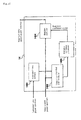
- FIG. 7 is a block diagram showing an example of the present invention.
- the difference from the configuration shown in FIG. 2 of the first embodiment is offset remover 22.
- Offset remover 22 removes the offset from the windowed, noisy speech and outputs the result.
- the simplest scheme for offset removal is achieved by calculating the means value of noisy speech for every frame to assume it as the offset and subtracting it from all the samples in the frame. It is also possible to average the means values for individual frames, over a multiple number of frames to determine the average value as the offset and substrate it.
- offset removal it is possible to improve transformation accuracy in the following Fourier transformer and hence improve the speech quality of the enhanced speech in the output.
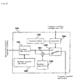
- FIG. 8 is a block diagram showing an example of the present invention.
- a noisy speech signal is supplied to input terminal 11 as a sequence of sample values.
- the noisy speech signal samples are supplied to frame divider 1 and divided into frames each including K/2 samples.
- K is assumed to be an even number.
- the noisy speech signal samples divided into frames are supplied to windowing processor 2, where the signal is multiplied by window function w(t).
- phase modifier 19 and amplitude modifier 18 are the same as those already described with reference to FIG. 2 .
- Multiplex multiplier 13 calculates a noisy speech power spectrum based on the amplitude-corrected, noisy speech amplitude spectrum and transmits it to band integrator 53.
- Band integrator 53 partly integrates the noisy speech power spectrum so as to reduce the number of independent frequency components, then transmits the result to estimated noise calculator 5, frequency-classified SNR (signal to noise ratio) calculator 6 and weighted noisy speech calculator 14.
- the operation of band integrator 53 is the same as that already described with reference to FIG. 2 .
- Weighted noisy speech calculator 14 calculates a weighted noisy speech power spectrum based on the noisy speech power spectrum supplied from multiplex multiplier 13 and transmits the result to estimated noise calculator 5.
- Estimated noise calculator 5 estimates the power spectrum of noise based on the noisy speech power spectrum, the weighted noisy speech power spectrum and the count value from counter 4 and transmits the result as an estimated noise power spectrum to frequency-classified SNR calculator 6.
- Frequency-classified SNR calculator 6 calculates SNRs for individual frequency bands based on the input noisy speech power spectrum and estimated noise power spectrum, and supplies the results as aposteriori SNRs to estimated apriori SNR calculator 7 and spectral gain generator 8.
- Estimated apriori SNR calculator 7 estimates apriori SNRs based on the input aposteriori SNRs and the corrected spectral gains supplied from spectral gain modifier 15 and transmits the result as estimated apriori SNRs to spectral gain generator 8.
- Spectral gain generator 8 receives as its input the aposteriori SNRs, the estimated apriori SNRs and the speech non-existence probability supplied from speech non-existence probability memory 21, generates spectral gains based on these inputs, and transmits the results as the spectral gains to spectral gain modifier 15.
- Spectral gain modifier 15 corrects the spectral gains using the input estimated apriori SNRs and spectral gains and supplies corrected spectral gains Gn(k)bar to multiplex multiplier 161.
- Multiplex multiplier 161 weights the corrected, noisy speech amplitude spectra supplied from Fourier transformer 3 by way of amplitude modifier 18 using corrected spectral gains Gn(k)bar supplied from spectral gain modifier 15 to thereby determine enhanced speech amplitude spectra
- bar is represented by the following equation.
- Hn(k) is a correction gain in amplitude modifier 18, having characteristics simulating the amplitude frequency response of high-pass filter 17.
- Inverse Fourier transformer 9 multiplies the enhanced speech amplitude
- X ⁇ n k X ⁇ n k ⁇ arg ⁇ Y n k + arg ⁇ H n k is executed.
- arg Hn(k) is the corrected phase in phase modifier 19, having characteristics that simulate the phase frequency response of high-pass filter 17.
- FIG. 9 is a block diagram showing the configuration of multiplex multiplier 13 shown in FIG. 8 .
- Multiplex multiplier 13 includes multipliers 1301 0 to 1301 K-1 , demultiplexers 1302 and 1303 and multiplexer 1304.
- the corrected, noisy speech amplitude spectrum as it is being multiplexed and supplied from amplitude modifier 18 in FIG. 8 , is separated into frequency-classified K samples by demultiplexers 1302 and 1303, and the separated samples are supplied to each of multipliers 1301 0 to 1301 K-1
- Multipliers 1301 0 to 1301 K-1 square the input signal and transmit the result to multiplexer 1304.
- Multiplexer 1304 multiplexes the input signals and output the multiplexed signal as a noisy speech power spectrum.
- FIG. 10 is a block diagram showing the configuration of weighted noisy speech calculator 14.
- Weighted noisy speech calculator 14 includes estimated noise memory 1401, frequency-classified SNR calculator 1402, multiplex non-linear processor 1405 and multiplex multiplier 1404.
- Estimated noise memory 1401 stores the estimated noise power spectrum supplied from estimated noise calculator 5 in FIG. 8 and outputs the estimated power spectrum stored one frame before, to frequency-classified SNR calculator 1402.
- Frequency-classified SNR calculator 1402 based on the estimated noise power spectrum supplied from estimated noise memory 1401 and the noisy speech power spectrum supplied from band integrator 53 in FIG. 8 , determines SNRs for individual frequency bands and outputs them to multiplex non-linear processor 1405.
- Multiplex multiplier 1404 calculates the product of the noisy speech power strum supplied from band integrator 53 in FIG. 8 and the weight coefficient vector supplied from multiplex non-linear processor 1405, for every frequency band, and outputs a weighted noisy speech power spectrum to estimated noise memory 5 in FIG. 8 .
- the configuration of multiplex multiplier 1404 is the same as that of multiplex multiplier 13 described with reference to FIG. 9 , so that detailed description is omitted.
- FIG. 11 is a block diagram showing the configuration of frequency-classified SNR calculator 1402 shown in FIG. 10 .
- Frequency-classified SNR calculator 1402 includes dividers 1421 0 to 1421 M-1 , demultiplexers 1422 and 1423 and multiplexer 1424.
- the noisy speech power spectrum supplied from band integrator 53 in FIG. 8 is transmitted to demultiplexer 1422.
- the estimated noise power spectrum supplied from estimated noise memory 1401 in FIG. 10 is transmitted to demultiplexer 1423.
- the noisy speech power spectrum and estimated noise power spectrum are separated by demultiplexer 1422 and demultiplexer 1423, respectively, into M samples corresponding to individual frequency components, and supplied to corresponding dividers 1421 0 to 1421 M-1 .
- divider 1421 0 to 1421 M-1 the supplied noisy speech power spectrum is divided by estimated noise power spectrum in accordance with the following equation to determine frequency-classified SNR ⁇ n(k)hut, which is transmitted to multiplexer 1424.
- Multiplexer 1424 multiplexes transmitted M frequency-classified SNRs and transmits the result to multiplex non-linear processor 1405 in Fig. 10 .
- FIG. 12 is a block diagram showing a configuration of multiplex non-linear processor 1405 included in weighted noisy speech calculator 14.
- Multiplex non-linear processor 1405 includes demultiplexer 1495, non-linear processors 1485 0 to 1485 M-1 and multiplexer 1475.
- Demultiplexer 1495 separates the SNRs supplied from frequency-classified SNR calculator 1402 in FIG. 10 into frequency-band-classified SNRs and transmits them to non-linear processors 1485 0 to 1485 M-1 .
- Non-linear processors 1485 0 to 1485 M-1 each have a non-linear function that outputs a real number value in accordance with the input value.
- FIG. 13 shows an example of a non-linear function.
- a and b are arbitrary real numbers.
- non-linear processors 1485 0 to 1485 M-1 in FIG. 12 the frequency-band-classified SNR supplied from demultiplexer 1495 is processed by a non-linear function to determine a weight coefficient and the result is output to multiplexer 1475. That is, non-linear processors 1485 0 to 1485 M-1 each output a weight coefficient ranging from 1 to 0 in accordance with the SNR. When the SNR is low, 1 is output and 0 is output when the SNR is high. Multiplexer 1475 multiplexes the weight coefficients output from non-linear processors 1485 0 to 1485 M-1 and outputs the result as a weight coefficient vector to multiplex multiplier 1404.
- the weight coefficients which are used in multiplex multiplier 1404 in FIG. 10 to multiply the noisy speech power spectrum, take values corresponding to the SNRs; the greater the SNR is, i.e., the greater the speech component that is contained in the noisy speech is, the smaller is the value of the weight coefficient.
- the noisy speech power spectrum is used.
- the noisy speech power spectrum used for updating estimated noise is weighted in accordance with the SNRs, it is possible to reduce the influence of the speech component contained in the noisy speech power spectrum, and hence to achieve noise estimation with a higher precision.
- SNR functions represented by other forms such as linear functions, high degree polynomials and the like can be also used.
- FIG. 14 is a block diagram showing a configuration of estimated speech noise calculator 5 shown in FIG. 8 .
- Noise estimating calculator 5 includes demultiplexers 501, 502, multiplexer 503 and frequency-classified estimated noise calculators 5040 to 504M-1.
- Demultiplexer 501 separates the weighted noisy speech power spectrum supplied from weighted noisy speech calculator 14 in FIG. 8 into frequency-band-classified weighted noisy speech power spectra and supplies them to each of frequency-classified estimated noise calculators 5040 to 504M-1.
- Demultiplexer 502 separates the noisy speech power spectrum supplied from band integrator 53 in FIG. 8 into frequency-band-classified noisy speech power spectra and supplies them to each of frequency-classified estimated noise calculators 504 0 to 504 M-1 .
- Frequency-classified estimated noise calculators 504 0 to 504 M-1 calculate frequency-classified estimated noise power spectra from the frequency-band-classified weighted noisy speech power spectra supplied from demultiplexer 501, the frequency-band-classified noisy speech power spectra supplied from demultiplexer 502 and the count value supplied from counter 4 in FIG. 8 and output them to multiplexer 503.
- Multiplexer 503 multiplexes the frequency-classified estimated noise power spectra supplied from frequency-classified estimated noise calculators 504 0 to 504 M-1 and outputs the estimated noise power spectrum to frequency-classified SNR calculator 6 and weighted noisy speech calculator 14 in FIG. 8 .
- the configuration and operation of frequency-classified estimated noise calculators 504 0 to 504 M-1 will be described in detail with reference to FIG. 15 .
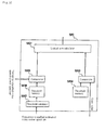
- FIG. 15 is a block diagram showing a configuration of frequency-classified estimated noise calculators 504 0 to 504 M-1 shown in FIG. 14 .
- Frequency-classified estimated noise calculator 504 includes update controller 520, register-length memory 5041, estimated noise memory 5042, switch 5044, shift register 5045, adder 5046, minimum-value selector 5047, divider 5048 and counter 5049.
- Switch 5044 is supplied with frequency-classified weighted noisy speech power spectrum from demultiplexer 501 in FIG. 14 . When switch 5044 closes the circuit, the frequency-classified weighted noisy speech power spectrum is transmitted to shift register 5045.
- Shift register 5045 in accordance with the control signal supplied from update controller 520, shifts the stored values in the internal register to the neighboring register.
- the shift register length is equal to the value stored in register-length memory 5041, which will be described later. All the register outputs from shift register 5045 are supplied to adder 5046. Adder 5046 adds all the supplied register outputs and transmits the result to divider 5048.
- update controller 520 is supplied with the count value, the frequency-classified noisy speech power spectrum and frequency-classified estimated noise power spectrum.
- Update controller 520 constantly outputs "1” until the count value reaches a predetermined set value. After the predetermined set value is reached, update controller 520 outputs "1" when the input noisy speech signal is determined to be noise and outputs "0" otherwise, and transmits the result to counter 5049, switch 5044 and shifter register 5045. Switch 5044 closes and opens the circuit when the signal supplied from update controller 520 is “1” and "0", respectively.
- Counter 5049 increases the count value when the signal supplied from update controller 520 is "1” and does not change the count value when the supplied signal is "0".
- Shift register 5045 picks up one sample of the signal samples supplied from switch 5044 when the signal supplied from update controller 520 is "1" and at the same time shifts the stored values in the internal register to the neighboring register. Supplied to minimum-value selector 5047 are the output from counter 5049 and the output from register-length memory 5041.
- Minimum-value selector 5047 selects the smaller one form among the supplied count value and register length, and transmits it to divider 5048.
- Divider 5048 divides the sum of the frequency-classified noisy speech power spectra, supplied from adder 5046, by the smaller one form among the count value and the register length, and outputs the quotient as frequency-classified estimated noise power spectrum An(k).
- N is the smaller value between the count value and the register length. Since the count value monotonously increases starting from zero, the division is done with the count value at the beginning and then is done with the register length.
- the mean value of the values stored in the shift register is determined by dividing by the register length. Since not many values have been stored in shift register 5045, division is done by the number of the registers in which values have been actually stored. The number of the registers in which values are actually stored is equal to the count value when the count value is smaller than the register length and is equal to the register length when the count value is greater than the register length.
- FIG. 16 is a block diagram showing a configuration of update controller 520 shown in FIG. 15 .
- Update controller 520 includes logical sum calculator 5201, comparators 5203 and 5205, threshold memorys 5204 and 5206 and threshold calculator 5207.
- the count value supplied from counter 4 in FIG. 8 is transmitted to comparator 5203.
- the threshold as the output from threshold memory 5204 is also transmitted to comparator 5203.
- Comparator 5203 makes a comparison between the supplied count value and the threshold and transmits "1" and "0" to logical sum calculator 5201 when the count value is smaller than the threshold and greater than the threshold, respectively.
- threshold calculator 5207 calculates a value corresponding to the frequency-classified estimated noise power spectrum supplied from estimated noise memory 5042 in FIG. 15 and outputs it as the threshold value to threshold memory 5206.
- Threshold memory 5206 stores the threshold output from threshold calculator 5207 and outputs the threshold stored in the preceding frame to comparator 5205.
- Comparator 5205 compares the threshold value supplied from threshold memory 5206 with the frequency-classified noisy speech power spectrum supplied from demultiplexer 502 in FIG. 14 , and outputs "1" and "0" to logical sum calculator 5201 when the frequency-classified noisy speech power spectrum is smaller and greater than the threshold, respectively.
- Logical sum calculator 5201 calculates the logical sum between the output value from comparator 5203 and the output value from comparator 5205 and outputs the calculated result to switch 5044, shift register 5045 and counter 5049 in FIG. 15 .
- update controller 520 outputs "1" not only for the initial state and silent periods but also when the noisy speech power is low even in non-silent periods. That is, estimated noise is updated. Since the threshold value is calculated for every frequency, it is possible to update estimated noise for every frequency.
- FIG. 17 is a block diagram showing a configuration of estimated apriori SNR calculator 7 shown in FIG. 8 .
- Estimated apriori SNR calculator 7 includes multiplexed value range limit processor 701, aposteriori SNR memory 702, spectral gain memory 703, multiplex multipliers 704 and 705, weight memory 706, multiplexed weighting accumulator 707 and adder 708.
- Aposteriori SNR memory 702 stores aposteriori SNR ⁇ (k) in the n-th frame and transmits aposteriori SNR yn-1 (k) in the (n-1)-th frame to multiplex multiplier 705.
- Spectral gain memory 703 stores corrected spectral gains Gn(k)bar in the n-th frame and transmits corrected spectral gains Gn-1(k)bar in the (n-1)-th frame to multiplex multiplier 704.
- Multiplex multiplier 704 squares supplied Gn(k)bar to determine G2n-1 (k)bar and transmits it to multiplex multiplier 705.
- Multiplex multiplier 705 multiplies G2n-1 (k)bar and yn-1(k) for K-0, 1, ..., M-1 to determine G2n-1 (k)bar.
- multiplex multipliers 704 and 705 are the same as that of multiplex multiplier 13 already described with reference to FIG. 9 , so that detailed description is omitted.
- the other terminal of adder 708 is supplied with -1, and the added result ⁇ n(k)-1 is transmitted to multiplexed limiter 701.
- Multiplexed limiter 701 performs an operation on the added result ⁇ n(k)-1, supplied from adder 708, by value range limit operator p[ ⁇ ] and transmits the result P[yn(k)-1] to adder 707 as temporary estimated SNR 921.
- P[x] is defined as the following equation.
- weight 923 Supplied also to multiplexed weighting accumulator 707 is weight 923 from weight memory 703.
- Multiplexed weighting accumulator 707 determines estimated apriori SNR 924 based on the supplied temporary estimated SNR 921, past SNR 922 and weight 923.
- weight 923 is represented by ⁇
- the estimated apriori SNR is represented by ⁇ n(k)hut
- ⁇ n(k)hut is calculated by the following equation.
- FIG. 18 is a block diagram showing a configuration of multiplexed limiter 701 shown in FIG. 17 .
- Multiplexed limiter 701 includes constant-value memory 7011, maximum-value selectors 7012 0 to 7012 M-1 , demultiplexer 7013 and multiplexer 7014. Supplied from adder 708 in FIG. 17 to demultiplexer 7013 is ⁇ n(k)-1.
- Demultiplexer 7013 separates the supplied ⁇ n(k)-1 into M frequency-band-classified components and supplies them to maximum-value selectors 7012 0 to 7012 M-1 .
- the other inputs of maximum-value selectors 7012 0 to 7012 M-1 are supplied with zero from constant-value memory 7011.
- Maximum-value selectors 7012 0 to 7012 M-1 compare ⁇ n(k)-1 with zero and transmits the greater value to multiplexer 7014. This maximum value select operation corresponds to the execution of aforementioned formula 12. Multiplexer 7014 multiplexes these values and outputs the result.
- FIG. 19 is a block diagram showing a configuration of multiplexed weighting accumulator 707 included in FIG. 17 .
- Multiplexed weighting accumulator 707 includes weighting adders 7071 0 to 7071 M-1 , demultiplexers 7072, 7074 and multiplexer 7075.
- Demultiplexer 7072 is supplied with P[ ⁇ n(k)-1] from multiplexed limiter 701 in FIG. 17 as temporary estimated SNR 921.
- Demultiplexer 7072 separates P[ ⁇ n(k)-1] into M frequency-band-classified components and transmits them as frequency-band-classified temporary estimated SNRs 921 0 to 921 M-1 to weighting adders 7071 0 to 7071 M-1 .
- Demultiplexer 7074 is supplied with G2n-1 (k) bar ⁇ n-1(k) from multiplex multiplier 705 in FIG. 17 as past estimated SNR 922. Demultiplexer 7074 separates G2n-1 (k) bar ⁇ n-1(k) into M frequency-band-classified components and transmits them as past frequency-band-classified estimated SNRs 922 0 to 922 M-1 to weighting adders 7071 0 to 7071 M-1 . On the other hand, weight 923 is also supplied to weighting adders 7071 0 to 7071 M-1 .
- Weighting adders 7071 0 to 7071 M-1 execute the weighted addition represented by aforementioned formula 13 and transmit frequency-band-classified estimated apriori SNRs 924 0 to 924 M-1 to multiplexer 7075. Multiplexer 7075 multiplexes frequency-band-classified estimated apriori SNRs 9240 to 924M-1 and outputs the result as estimated apriori SNR 924.
- the operation and configuration of weighting adders 7071 0 to 7071 M-1 will be described next with reference to FIG. 20 .
- FIG. 20 is a block diagram showing a configuration of weighting adders 7071 0 to 7071 M-1 shown in FIG. 19 .
- Weighting adder 7071 includes multipliers 7091 and 7093, constant multiplier 7095, adders 7092 and 7094.
- Frequency-band-classified temporary estimated SNR 921 from demultiplexer 7072 in FIG. 19 past frequency-band-classified SNR 922 from demultiplexer 7074 in FIG. 19 and weight 923 from weight memory 706 in FIG. 17 are supplied as an input.
- Wight 923 having a value of ⁇ is transmitted to constant multiplier 7095 and multiplier 7093.
- Constant multiplier 7095 multiplies the input signal by -1 and transmits the obtained - ⁇ to adder 7094.
- adder 7094 The other input of adder 7094 is supplied with 1, so that adder 7094 outputs the sum, i.e., 1- ⁇ .
- This output, 1- ⁇ is supplied to multiplier 7091, and multiplied therein by the other input, i.e., frequency-band-classified temporary estimated SNR P[ ⁇ n(k)-1].
- the resultant product, (1- ⁇ )P[ ⁇ n(k)-1] is transmitted to adder 7092.
- multiplier 7093 ⁇ supplied as weight 923 is multiplied by past estimated SNR 922, and the resultant product, ⁇ G2n-1 (k) bar yn-1 (k) is transmitted to adder 7092.
- Adder 7092 outputs the sum of (1- ⁇ )P[ ⁇ n(k)-1] and ⁇ G2n-1 (k) bar ⁇ n-1(k) as frequency-band-classified estimated apriori SNR 904.
- FIG. 21 is a block diagram showing spectral gain generator 8 shown in FIG. 8 .
- Spectral gain generator 8 includes MMSE STSA gain function value calculator 811, generalized likelihood ratio calculator 812 and spectral gain calculator 814.
- MMSE STSA gain function value calculator 811 generalized likelihood ratio calculator 812
- spectral gain calculator 814 based on the formulae described in non-patent document 2 ( IEEE TRANSACTIONSON ACOUSTICS, SPEECH, AND SIGNAL PROCESSING, VOL.32, NO.6, PP.1109-1121, DEC, 1984 ), the method of calculating spectral gains will be described.
- the frame number is n
- the frequency number is k
- ⁇ n(k) represents the frequency-classified aposteriori SNR supplied from frequency-classified SNR calculator 6 in FIG. 8
- ⁇ n(k)hut represents the frequency-classified estimated apriori SNR supplied from estimated apriori SNR calculator 7 in FIG. 8
- q represents the speech non-existence probability supplied from speech non-existence probability memory 21 in FIG. 8 .
- MMSE STSA gain function value calculator 811 calculates an MMSE STSA gain function value for every frequency band and output it to spectral gain calculator 814.
- Each MMSE STSA gain function value Gn(k) for each frequency band is given as
- n k ⁇ 2 ⁇ ⁇ n k ⁇ n k ⁇ exp - ⁇ n k 2 ⁇ 1 + ⁇ n k ⁇ I 0 ⁇ n k 2 + ⁇ n k ⁇ I 1 ⁇ n k 2
- I0(z) is the 0-th order modified Bessel function
- I1(z) is the 1 st order modified Bessel function. Reference to the modified Bessel functions is found in non-patent document 3 ( page 374G, Iwanami Shoten, Sugakujiten, 1985 ).
- Generalized likelihood ratio calculator 812 calculates a generalized likelihood ratio for every frequency band and transmits it to spectral gain calculator 814.
- Generalized likelihood ratio An(k) for an individual frequency band is given as:
- Spectral gain calculator 814 calculates a spectral gain for every frequency, from MMSE STSA gain function value Gn(k) supplied from MMSE STSA gain function value calculator 811 and generalized likelihood ratio An(k) supplied from generalized likelihood ratio calculator 812, and outputs the result to spectral gain modifier 15 in FIG. 8 .
- Spectral gain Gn(k)bar for every frequency band is given as
- G ⁇ n k ⁇ n k ⁇ n k + 1 ⁇ G n k
- FIG. 22 is a block diagram showing a configuration of spectral gain modifier 15 shown in FIG. 8 .
- Spectral gain modifier 15 includes frequency-classified spectral gain modifiers 1501 0 to 1501 M-1 , demultiplexers 1502 and 1503 and multiplexer 1504.
- Demultiplexer 1502 separates estimated apriori SNR supplied from estimated apriori SNR calculator 7 in FIG. 8 into frequency-band-classified components and outputs them to individual frequency-classified spectral gain modifiers 1501 0 to 1501 M-1 .
- Demultiplexer 1503 separates the spectral gains supplied from spectral gain generator 8 in FIG.
- Frequency- classified spectral gain modifiers 1501 0 to 1501 M-1 calculate frequency-band-classified corrected spectral gains, from frequency-band-classified estimated apriori SNRs supplied from demultiplexer 1502 and frequency-band-classified spectral gains supplied from demultiplexer 1503, and output them to multiplexer 1504.
- Multiplexer 1504 multiplexes the frequency-band-classified corrected spectral gains supplied from frequency-classified spectral gain modifiers 1501 0 to 1501 M-1 and outputs them as corrected spectral gains to multiplex multiplier 16 and estimated apriori SNR calculator 7 in FIG. 8 .
- frequency-classified spectral gain modifiers 1501 0 to 1501 M-1 will be described in detail.
- FIG. 23 is a block diagram showing the configuration of frequency-classified spectral gain modifiers 1501 0 to 1501 M-1 included in spectral gain modifier 15.
- Frequency-classified spectral gain modifier 1501 includes maximum-value selector 1591, minimum-spectral-gain memory 1592, threshold memory 1593, comparator 1594, switch 1595, modified-value memory 1596 and multiplier 1597.
- Comparator 1594 makes a comparison between the threshold supplied from threshold memory 1593 and the frequency-band-classified estimated apriori SNR supplied from demultiplexer 1502 in FIG. 22 , and supplies "0" and "1" to switch 1595 when the frequency-band-classified estimated apriori SNR is greater and smaller than the threshold, respectively.
- Switch 1595 outputs the frequency-band-classified estimated apriori SNR supplied from demultiplexer 1503 in FIG. 22 to multiplier 1597 when the output value from comparator 1594 is "1" and to maximum-value selector 1591 and when the output value is "0". More clearly, when frequency-band-classified estimated apriori SNR is smaller than the threshold value, the spectral gain is corrected. Multiplier 1597 calculates the product of the output value from switch 1595 and the output value from modified-value memory 1596 and transmits the product to maximum-value selector 1591.
- minimum-spectral-gain memory 1592 supplies the lower limit of the spectral gains that are stored to maximum-value selector 1591.
- Maximum-value selector 1591 compares the frequency-band-classified spectral gain supplied from demultiplexer 1503 in FIG. 22 or the product calculated by multiplier 1597 with the minimum spectral gain supplied from minimum-spectral-gain memory 1592, and outputs the greater value to multiplexer 1504 in FIG. 22 . That is, the spectral gain necessarily takes a greater value than the lower limit being stored in minimum-spectral-gain memory 1592.
- the least mean square error short period spectrum amplitude method has been assumed as the scheme for suppressing noise
- other methods may also be applied. Examples of such methods include the Wiener filtering method, disclosed in non-patent document 4 ( PROCEEDINGS OF THE IEEE, VOL.67, NO.12, PP.1586-1604, DEC, 1979 ), a spectraubtracting method disclosed in non-patent document 5 ( IEEETRANSACTIONS ON ACOUSTICS, SPEECH, AND SIGNAL PROCESSING, VOL.27, NO.2,PP.113-129, APR, 1979 ). However, description of detailed configurational examples of these is omitted.
- the noise suppressing apparatus of each of the aforementioned embodiments can be configured by a computer apparatus made up of a memory device for storing programs, a control portion equipped with input keys and switches, a display device such as an LCD or the like and a control device that receives input from the control portion and controls the operation of each part.
- the operation in the noise suppressing apparatus of each of the aforementioned embodiments can be realized by letting the control device execute the program stored in memory.
- the program may be stored beforehand in memory or may be written in CD-ROM or any other recording medium that the user prefers. It is also possible to provide the program by way of a network.
Landscapes
- Engineering & Computer Science (AREA)
- Computational Linguistics (AREA)
- Quality & Reliability (AREA)
- Signal Processing (AREA)
- Health & Medical Sciences (AREA)
- Audiology, Speech & Language Pathology (AREA)
- Human Computer Interaction (AREA)
- Physics & Mathematics (AREA)
- Acoustics & Sound (AREA)
- Multimedia (AREA)
- Noise Elimination (AREA)
- Cable Transmission Systems, Equalization Of Radio And Reduction Of Echo (AREA)
Claims (6)
- Ein Rauschunterdrückungsverfahren, aufweisend:Transformieren eines Eingangs-Audiosignals in ein Frequenz-Domänensignal, welches eine Mehrzahl von Frequenzkomponenten aufweist;Ermitteln spektraler Verstärkungen basierend auf den Frequenz-Domänensignalen, wobei eine Anzahl von spektralen Verstärkungen kleiner ist als eine Anzahl von Frequenzkomponenten in dem Frequenz-Domänensignal, undGewichten der Frequenz-Domänensignale durch die spektralen Verstärkungen, um Rauschen zu unterdrücken, das in dem Eingangssignal enthalten ist,wobei zumindest eine der spektralen Verstärkungen verwendet wird für multiple Frequenzkomponenten.
- Das Rauschunterdrückungsverfahren nach anspruch 1, wobei in dem Schritt zur Ermittlung der spektralen Verstärkung die Frequenz-Domänensignale, die eine Mehrzahl von durch die spektrale Verstärkung zu verwendenden Frequenzkomponenten einschließen, verwendet werden, um geschätztes Rauschen zu ermitteln, das der Mehrzahl von Frequenzkomponenten gemeinsam ist, und wobei die spektrale Verstärkung ermittelt wird basierend auf dem geschätzten Rauschen.
- Eine Rauschunterdrückungsvorrichtung zum Unterdrücken von Rauschen, aufweisend:Einen Transformer zum Transformieren eines Eingangs-Audiosignals in Frequenz-Domänensignale, welche eine Mehrzahl von Frequenzkomponenten aufweisen;einen spektralen Verstärkungsgenerator zum Ermitteln spektraler Verstärkungen basierend auf den Frequenz-Domänensignalen, wobei eine Anzahl von spektralen Verstärkungen geringer ist als eine Anzahl von Frequenzkomponenten in den Frequenz-Domänensignalen;ein Multiplizierer zum Gewichten der Frequenz-Domänensignale mit den spektralen Verstärkungen, undeinen Frequenzkomponentenintegrator zum Integrieren von Frequenzkomponenten der Frequenz-Domänensignale, um integrierte Frequenz-Domänensignale zu ermitteln,wobei der spektrale Verstärkungsgenerator spektrale Verstärkungen ermittelt basierend auf den integrierten Frequenz-Domänensignalen und der Multiplizierer zumindest eine der spektralen Verstärkungen für multiple Frequenzkomponenten verwendet, um die Frequenz-Domänensignale zu gewichten.
- Die Rauschunterdrückungsvorrichtung nach Anspruch 3, ferner aufweisend:Einen Rausch-Schätzer zum Ermitteln geschätzten Rauschens, das der Mehrzahl von Frequenzkomponenten gemeinsam ist, basierend auf den integrierten Frequenz-Domänensignalen,wobei der spektrale Verstärkungsgenerator die spektralen Verstärkungen basierend auf dem geschätzten Rauschen ermittelt.
- Ein Computerprogramm zum Durchführen eines Signalprozesses, bei dem zur Unterdrückung von Rauschen, das in einem Eingangs-Audiosignal enthalten ist, das Eingangssignal transformiert wird in Frequenz-Domänensignale, welche eine Mehrzahl von Frequenzkomponenten aufweisen, wobei spektrale Verstärkungen ermittelt werden basierend auf den Frequenz-Domänensignalen, wobei eine Anzahl von spektralen Verstärkungen geringer ist als die Anzahl von Frequenzkomponenten in den Frequenz-Domänensignalen und wobei die Frequenz-Domänensignale gewichtet werden durch spektrale Verstärkungen, wobei das Computerprogramm angepasst ist, einen Computer zu veranlassen auszuführen:Ein Verfahren zum Integrieren von Frequenzkomponenten der Frequenz-Domänensignale, um integrierte Frequenz-Domänensignale zu ermitteln;ein Verfahren zum Ermitteln der spektralen Verstärkungen basierend auf den integrierten Frequenz-Domänensignalen; undein Verfahren zum Verwenden zumindest einer der spektralen Verstärkungen für multiple Frequenzkomponenten, um die Frequenz-Domänensignale zu gewichten.
- Das Computerprogramm nach Anspruch 5, ferner angepasst, um einen Computer zu veranlassen, auszuführen:Ein Verfahren zum Ermitteln geschätzten Rauschens, das der Mehrzahl von Frequenzkomponenten gemeinsam ist, basierend auf den integrierten Frequenz-Domänensignalen und zum Ermitteln der spektralen Verstärkungen basierend auf dem geschätzten Rauschen.
Applications Claiming Priority (2)
| Application Number | Priority Date | Filing Date | Title |
|---|---|---|---|
| JP2005255748 | 2005-09-02 | ||
| EP06796943.6A EP1921609B1 (de) | 2005-09-02 | 2006-08-29 | Rauschunterdrückungsverfahren und vorrichtung und computerprogramm |
Related Parent Applications (3)
| Application Number | Title | Priority Date | Filing Date |
|---|---|---|---|
| EP06796943.6 Division | 2006-08-29 | ||
| EP06796943.6A Division-Into EP1921609B1 (de) | 2005-09-02 | 2006-08-29 | Rauschunterdrückungsverfahren und vorrichtung und computerprogramm |
| EP06796943.6A Division EP1921609B1 (de) | 2005-09-02 | 2006-08-29 | Rauschunterdrückungsverfahren und vorrichtung und computerprogramm |
Publications (2)
| Publication Number | Publication Date |
|---|---|
| EP2555190A1 EP2555190A1 (de) | 2013-02-06 |
| EP2555190B1 true EP2555190B1 (de) | 2014-07-02 |
Family
ID=37808780
Family Applications (2)
| Application Number | Title | Priority Date | Filing Date |
|---|---|---|---|
| EP12190386.8A Ceased EP2555190B1 (de) | 2005-09-02 | 2006-08-29 | Verfahren, Vorrichtung und Computerprogramm zur Rauschunterdrückung |
| EP06796943.6A Ceased EP1921609B1 (de) | 2005-09-02 | 2006-08-29 | Rauschunterdrückungsverfahren und vorrichtung und computerprogramm |
Family Applications After (1)
| Application Number | Title | Priority Date | Filing Date |
|---|---|---|---|
| EP06796943.6A Ceased EP1921609B1 (de) | 2005-09-02 | 2006-08-29 | Rauschunterdrückungsverfahren und vorrichtung und computerprogramm |
Country Status (6)
| Country | Link |
|---|---|
| US (1) | US9318119B2 (de) |
| EP (2) | EP2555190B1 (de) |
| JP (2) | JP4172530B2 (de) |
| KR (1) | KR100927897B1 (de) |
| CN (1) | CN101091209B (de) |
| WO (1) | WO2007026691A1 (de) |
Families Citing this family (46)
| Publication number | Priority date | Publication date | Assignee | Title |
|---|---|---|---|---|
| WO2007026691A1 (ja) * | 2005-09-02 | 2007-03-08 | Nec Corporation | 雑音抑圧の方法及び装置並びにコンピュータプログラム |
| NL1032724C2 (nl) * | 2006-10-23 | 2008-04-25 | Ten Cate Thiolon Bv | Kunstgrasveld, in het bijzonder voor een kunstgrassportveld. |
| JP5483000B2 (ja) * | 2007-09-19 | 2014-05-07 | 日本電気株式会社 | 雑音抑圧装置、その方法及びプログラム |
| JP4660578B2 (ja) * | 2008-08-29 | 2011-03-30 | 株式会社東芝 | 信号補正装置 |
| WO2010032405A1 (ja) * | 2008-09-16 | 2010-03-25 | パナソニック株式会社 | 音声分析装置、音声分析合成装置、補正規則情報生成装置、音声分析システム、音声分析方法、補正規則情報生成方法、およびプログラム |
| ES2690677T3 (es) * | 2009-02-09 | 2018-11-21 | Nec Corporation | Sistema de control de la trayectoria, dispositivo de control de la trayectoria, método de control de la trayectoria y producto de programa informático |
| WO2011004299A1 (en) * | 2009-07-07 | 2011-01-13 | Koninklijke Philips Electronics N.V. | Noise reduction of breathing signals |
| JP5294085B2 (ja) | 2009-11-06 | 2013-09-18 | 日本電気株式会社 | 情報処理装置、その付属装置、情報処理システム、その制御方法並びに制御プログラム |
| JP2011100029A (ja) | 2009-11-06 | 2011-05-19 | Nec Corp | 信号処理方法、情報処理装置、及び信号処理プログラム |
| JP5787126B2 (ja) | 2009-11-06 | 2015-09-30 | 日本電気株式会社 | 信号処理方法、情報処理装置、及び信号処理プログラム |
| JP5299233B2 (ja) | 2009-11-20 | 2013-09-25 | ソニー株式会社 | 信号処理装置、および信号処理方法、並びにプログラム |
| JP5325134B2 (ja) * | 2010-02-04 | 2013-10-23 | 日本電信電話株式会社 | 反響消去方法、反響消去装置、そのプログラムおよび記録媒体 |
| US8989403B2 (en) | 2010-03-09 | 2015-03-24 | Mitsubishi Electric Corporation | Noise suppression device |
| WO2011148860A1 (ja) | 2010-05-24 | 2011-12-01 | 日本電気株式会社 | 信号処理方法、情報処理装置、及び信号処理プログラム |
| WO2011148861A1 (ja) | 2010-05-25 | 2011-12-01 | 日本電気株式会社 | 信号処理方法、情報処理装置、及び信号処理プログラム |
| JP5919516B2 (ja) * | 2010-07-26 | 2016-05-18 | パナソニックIpマネジメント株式会社 | 多入力雑音抑圧装置、多入力雑音抑圧方法、プログラムおよび集積回路 |
| JP2012058358A (ja) * | 2010-09-07 | 2012-03-22 | Sony Corp | 雑音抑圧装置、雑音抑圧方法およびプログラム |
| CN103250208B (zh) * | 2010-11-24 | 2015-06-17 | 日本电气株式会社 | 信号处理装置和信号处理方法 |
| CN103270772B (zh) | 2010-11-25 | 2017-06-06 | 日本电气株式会社 | 信号处理设备、信号处理方法 |
| WO2012114628A1 (ja) * | 2011-02-26 | 2012-08-30 | 日本電気株式会社 | 信号処理装置、信号処理方法、及び記憶媒体 |
| JP2014123011A (ja) * | 2012-12-21 | 2014-07-03 | Sony Corp | 雑音検出装置および方法、並びに、プログラム |
| RU2640442C2 (ru) * | 2012-12-31 | 2018-01-09 | Филип Моррис Продактс С.А. | Курительное изделие, содержащее ограничитель потока в полой трубке |
| CN104103278A (zh) * | 2013-04-02 | 2014-10-15 | 北京千橡网景科技发展有限公司 | 一种实时语音去噪的方法和设备 |
| CN104702558B (zh) * | 2013-12-05 | 2018-03-09 | 上海数字电视国家工程研究中心有限公司 | Ofdm系统的相位噪声消除方法 |
| US20170011753A1 (en) * | 2014-02-27 | 2017-01-12 | Nuance Communications, Inc. | Methods And Apparatus For Adaptive Gain Control In A Communication System |
| US10149047B2 (en) * | 2014-06-18 | 2018-12-04 | Cirrus Logic Inc. | Multi-aural MMSE analysis techniques for clarifying audio signals |
| EP2963646A1 (de) * | 2014-07-01 | 2016-01-06 | Fraunhofer-Gesellschaft zur Förderung der angewandten Forschung e.V. | Decodierer und Verfahren zur Decodierung eines Audiosignals, Codierer und Verfahren zur Codierung eines Audiosignals |
| CN104134444B (zh) * | 2014-07-11 | 2017-03-15 | 福建星网视易信息系统有限公司 | 一种基于mmse的歌曲去伴奏方法和装置 |
| CN104090253B (zh) * | 2014-07-14 | 2016-12-07 | 中国电子科技集团公司第四十一研究所 | 一种基于数据模型的校准件定标数据中噪声的处理方法 |
| CN105635453B (zh) * | 2015-12-28 | 2020-12-29 | 上海博泰悦臻网络技术服务有限公司 | 一种通话音量自动调节方法、系统、车载设备及汽车 |
| WO2017119284A1 (ja) | 2016-01-08 | 2017-07-13 | 日本電気株式会社 | 信号処理装置、利得調整方法および利得調整プログラム |
| CN106228993B (zh) * | 2016-09-29 | 2020-02-07 | 北京奇艺世纪科技有限公司 | 一种消除噪声的方法和装置以及电子设备 |
| AU2017402614B2 (en) * | 2017-03-10 | 2022-03-31 | James Jordan Rosenberg | System and method for relative enhancement of vocal utterances in an acoustically cluttered environment |
| CN108281149B (zh) * | 2017-12-29 | 2021-08-27 | 芯原微电子(北京)有限公司 | 一种基于加Blackman窗的FIR滤波器的音频采样率转换方法及系统 |
| WO2020039598A1 (ja) * | 2018-08-24 | 2020-02-27 | 日本電気株式会社 | 信号処理装置、信号処理方法および信号処理プログラム |
| CN109613336B (zh) * | 2018-12-07 | 2020-12-01 | 中国电子科技集团公司第四十一研究所 | 一种任意长度fft多模信号频域分析装置及方法 |
| CN110164467B (zh) | 2018-12-18 | 2022-11-25 | 腾讯科技(深圳)有限公司 | 语音降噪的方法和装置、计算设备和计算机可读存储介质 |
| KR102569365B1 (ko) * | 2018-12-27 | 2023-08-22 | 삼성전자주식회사 | 가전기기 및 이의 음성 인식 방법 |
| CN109829899B (zh) * | 2019-01-18 | 2020-08-07 | 创新奇智(广州)科技有限公司 | 一种针对钢卷端面缺陷检测的背景抑制算法 |
| CN110931033B (zh) * | 2019-11-27 | 2022-02-18 | 深圳市悦尔声学有限公司 | 一种麦克风内置耳机的语音聚焦增强方法 |
| CN111163399A (zh) * | 2019-12-26 | 2020-05-15 | 九江慧明电子科技有限公司 | 一种具有高灵敏度的音频系统及其调节方法 |
| CN111131965A (zh) * | 2019-12-26 | 2020-05-08 | 九江慧明电子科技有限公司 | 一种带有保护功能的音频系统及其调节方法 |
| CN111402917B (zh) * | 2020-03-13 | 2023-08-04 | 北京小米松果电子有限公司 | 音频信号处理方法及装置、存储介质 |
| CN113936670A (zh) * | 2020-06-28 | 2022-01-14 | 腾讯科技(深圳)有限公司 | 丢包重发方法、系统、装置、计算机可读存储介质及设备 |
| CN111899752B (zh) * | 2020-07-13 | 2023-01-10 | 紫光展锐(重庆)科技有限公司 | 快速计算语音存在概率的噪声抑制方法及装置、存储介质、终端 |
| CN113516992A (zh) * | 2020-08-21 | 2021-10-19 | 腾讯科技(深圳)有限公司 | 一种音频处理方法、装置、智能设备及存储介质 |
Family Cites Families (41)
| Publication number | Priority date | Publication date | Assignee | Title |
|---|---|---|---|---|
| KR940009391B1 (ko) | 1985-07-01 | 1994-10-07 | 모토로라 인코포레이티드 | 잡음 억제 시스템 |
| US4630304A (en) | 1985-07-01 | 1986-12-16 | Motorola, Inc. | Automatic background noise estimator for a noise suppression system |
| US4628529A (en) * | 1985-07-01 | 1986-12-09 | Motorola, Inc. | Noise suppression system |
| IL84948A0 (en) * | 1987-12-25 | 1988-06-30 | D S P Group Israel Ltd | Noise reduction system |
| US5432859A (en) * | 1993-02-23 | 1995-07-11 | Novatel Communications Ltd. | Noise-reduction system |
| US5544250A (en) * | 1994-07-18 | 1996-08-06 | Motorola | Noise suppression system and method therefor |
| JP3338573B2 (ja) | 1994-11-01 | 2002-10-28 | ユナイテッド・モジュール・コーポレーション | サブバンド分割演算回路 |
| JP3591068B2 (ja) * | 1995-06-30 | 2004-11-17 | ソニー株式会社 | 音声信号の雑音低減方法 |
| JPH0944186A (ja) | 1995-07-31 | 1997-02-14 | Matsushita Electric Ind Co Ltd | 雑音抑制装置 |
| US5659622A (en) | 1995-11-13 | 1997-08-19 | Motorola, Inc. | Method and apparatus for suppressing noise in a communication system |
| JP3522954B2 (ja) * | 1996-03-15 | 2004-04-26 | 株式会社東芝 | マイクロホンアレイ入力型音声認識装置及び方法 |
| US6144937A (en) | 1997-07-23 | 2000-11-07 | Texas Instruments Incorporated | Noise suppression of speech by signal processing including applying a transform to time domain input sequences of digital signals representing audio information |
| FR2768547B1 (fr) * | 1997-09-18 | 1999-11-19 | Matra Communication | Procede de debruitage d'un signal de parole numerique |
| US6415253B1 (en) * | 1998-02-20 | 2002-07-02 | Meta-C Corporation | Method and apparatus for enhancing noise-corrupted speech |
| JPH11289312A (ja) | 1998-04-01 | 1999-10-19 | Toshiba Tec Corp | マルチキャリア無線通信装置 |
| US6381570B2 (en) * | 1999-02-12 | 2002-04-30 | Telogy Networks, Inc. | Adaptive two-threshold method for discriminating noise from speech in a communication signal |
| US6618701B2 (en) * | 1999-04-19 | 2003-09-09 | Motorola, Inc. | Method and system for noise suppression using external voice activity detection |
| JP2000357969A (ja) | 1999-06-16 | 2000-12-26 | Victor Co Of Japan Ltd | オーディオ信号の符号化装置 |
| GB2355834A (en) * | 1999-10-29 | 2001-05-02 | Nokia Mobile Phones Ltd | Speech recognition |
| US6757395B1 (en) * | 2000-01-12 | 2004-06-29 | Sonic Innovations, Inc. | Noise reduction apparatus and method |
| US7058572B1 (en) * | 2000-01-28 | 2006-06-06 | Nortel Networks Limited | Reducing acoustic noise in wireless and landline based telephony |
| US6766292B1 (en) * | 2000-03-28 | 2004-07-20 | Tellabs Operations, Inc. | Relative noise ratio weighting techniques for adaptive noise cancellation |
| US6523003B1 (en) * | 2000-03-28 | 2003-02-18 | Tellabs Operations, Inc. | Spectrally interdependent gain adjustment techniques |
| US6529868B1 (en) * | 2000-03-28 | 2003-03-04 | Tellabs Operations, Inc. | Communication system noise cancellation power signal calculation techniques |
| US6701291B2 (en) * | 2000-10-13 | 2004-03-02 | Lucent Technologies Inc. | Automatic speech recognition with psychoacoustically-based feature extraction, using easily-tunable single-shape filters along logarithmic-frequency axis |
| JP4282227B2 (ja) * | 2000-12-28 | 2009-06-17 | 日本電気株式会社 | ノイズ除去の方法及び装置 |
| CN1282155C (zh) | 2001-03-28 | 2006-10-25 | 三菱电机株式会社 | 噪声抑制装置和方法 |
| WO2002082427A1 (en) * | 2001-04-09 | 2002-10-17 | Koninklijke Philips Electronics N.V. | Speech enhancement device |
| JP2002316580A (ja) | 2001-04-24 | 2002-10-29 | Murakami Corp | カメラ内蔵ミラー装置 |
| JP3457293B2 (ja) * | 2001-06-06 | 2003-10-14 | 三菱電機株式会社 | 雑音抑圧装置及び雑音抑圧方法 |
| EP1278185A3 (de) * | 2001-07-13 | 2005-02-09 | Alcatel | Verfahren zur Verbesserung von Geräuschunterdrückung bei der Sprachübertragung |
| JP2003131689A (ja) | 2001-10-25 | 2003-05-09 | Nec Corp | ノイズ除去方法及び装置 |
| WO2004006625A1 (en) * | 2002-07-08 | 2004-01-15 | Koninklijke Philips Electronics N.V. | Audio processing |
| US20040148160A1 (en) * | 2003-01-23 | 2004-07-29 | Tenkasi Ramabadran | Method and apparatus for noise suppression within a distributed speech recognition system |
| JP4247037B2 (ja) * | 2003-01-29 | 2009-04-02 | 株式会社東芝 | 音声信号処理方法と装置及びプログラム |
| JP4162604B2 (ja) * | 2004-01-08 | 2008-10-08 | 株式会社東芝 | 雑音抑圧装置及び雑音抑圧方法 |
| JP4542790B2 (ja) * | 2004-01-16 | 2010-09-15 | 株式会社東芝 | ノイズサプレッサ及びノイズサプレッサを備えた音声通信装置 |
| US7492889B2 (en) * | 2004-04-23 | 2009-02-17 | Acoustic Technologies, Inc. | Noise suppression based on bark band wiener filtering and modified doblinger noise estimate |
| WO2007026691A1 (ja) | 2005-09-02 | 2007-03-08 | Nec Corporation | 雑音抑圧の方法及び装置並びにコンピュータプログラム |
| GB2466668A (en) * | 2009-01-06 | 2010-07-07 | Skype Ltd | Speech filtering |
| WO2019021609A1 (ja) | 2017-07-28 | 2019-01-31 | シャープ株式会社 | カメラモジュール製造方法およびカメラモジュール製造装置 |
-
2006
- 2006-08-29 WO PCT/JP2006/316963 patent/WO2007026691A1/ja active Application Filing
- 2006-08-29 EP EP12190386.8A patent/EP2555190B1/de not_active Ceased
- 2006-08-29 US US11/794,563 patent/US9318119B2/en not_active Expired - Fee Related
- 2006-08-29 KR KR1020077014813A patent/KR100927897B1/ko active IP Right Grant
- 2006-08-29 JP JP2007505297A patent/JP4172530B2/ja not_active Expired - Fee Related
- 2006-08-29 CN CN2006800015392A patent/CN101091209B/zh not_active Expired - Fee Related
- 2006-08-29 EP EP06796943.6A patent/EP1921609B1/de not_active Ceased
-
2008
- 2008-04-21 JP JP2008110432A patent/JP2008203879A/ja active Pending
Also Published As
| Publication number | Publication date |
|---|---|
| JP4172530B2 (ja) | 2008-10-29 |
| JPWO2007026691A1 (ja) | 2009-03-26 |
| US9318119B2 (en) | 2016-04-19 |
| US20100010808A1 (en) | 2010-01-14 |
| CN101091209A (zh) | 2007-12-19 |
| CN101091209B (zh) | 2010-06-09 |
| KR20070088751A (ko) | 2007-08-29 |
| EP1921609B1 (de) | 2014-07-16 |
| WO2007026691A1 (ja) | 2007-03-08 |
| JP2008203879A (ja) | 2008-09-04 |
| EP1921609A4 (de) | 2012-07-25 |
| KR100927897B1 (ko) | 2009-11-23 |
| EP2555190A1 (de) | 2013-02-06 |
| EP1921609A1 (de) | 2008-05-14 |
Similar Documents
| Publication | Publication Date | Title |
|---|---|---|
| EP2555190B1 (de) | Verfahren, Vorrichtung und Computerprogramm zur Rauschunterdrückung | |
| EP1930880B1 (de) | Verfahren und vorrichtung zur rauschunterdrückung und computerprogramm | |
| JP4670483B2 (ja) | 雑音抑圧の方法及び装置 | |
| US8073147B2 (en) | Dereverberation method, apparatus, and program for dereverberation | |
| JP5435204B2 (ja) | 雑音抑圧の方法、装置、及びプログラム | |
| EP1349148B1 (de) | Verfahren und Vorrichtung zur Rauschschätzung in einem Tonsignal | |
| DK2337224T3 (en) | Filter unit and method for generating subband filter pulse response | |
| JP5252661B2 (ja) | エイリアシング効果抑制のための実副帯信号の処理装置及び処理方法 | |
| AU2010206229B2 (en) | Apparatus, method and computer program for obtaining a parameter describing a variation of a signal characteristic of a signal | |
| EP1903558B1 (de) | Verfahren und Vorrichtung zur Interpolation von Audiosignalen | |
| JP2008216721A (ja) | 雑音抑圧の方法、装置、及びプログラム | |
| JP2003140700A (ja) | ノイズ除去方法及び装置 | |
| EP2755205B1 (de) | Subband-Verarbeitung zur Komplexitätsverringerung |
Legal Events
| Date | Code | Title | Description |
|---|---|---|---|
| PUAI | Public reference made under article 153(3) epc to a published international application that has entered the european phase |
Free format text: ORIGINAL CODE: 0009012 |
|
| AC | Divisional application: reference to earlier application |
Ref document number: 1921609 Country of ref document: EP Kind code of ref document: P |
|
| AK | Designated contracting states |
Kind code of ref document: A1 Designated state(s): DE FR GB IT |
|
| 17P | Request for examination filed |
Effective date: 20130806 |
|
| RBV | Designated contracting states (corrected) |
Designated state(s): DE FR GB IT |
|
| REG | Reference to a national code |
Ref country code: DE Ref legal event code: R079 Ref document number: 602006042185 Country of ref document: DE Free format text: PREVIOUS MAIN CLASS: G10L0021020000 Ipc: G10L0021020800 |
|
| GRAP | Despatch of communication of intention to grant a patent |
Free format text: ORIGINAL CODE: EPIDOSNIGR1 |
|
| RIC1 | Information provided on ipc code assigned before grant |
Ipc: G10L 19/02 20130101ALN20131206BHEP Ipc: G10L 21/0216 20130101ALN20131206BHEP Ipc: G10L 21/0208 20130101AFI20131206BHEP |
|
| RIC1 | Information provided on ipc code assigned before grant |
Ipc: G10L 21/0216 20130101ALN20131213BHEP Ipc: G10L 19/02 20130101ALN20131213BHEP Ipc: G10L 21/0208 20130101AFI20131213BHEP |
|
| INTG | Intention to grant announced |
Effective date: 20140110 |
|
| RIC1 | Information provided on ipc code assigned before grant |
Ipc: G10L 21/0216 20130101ALN20131220BHEP Ipc: G10L 21/0208 20130101AFI20131220BHEP Ipc: G10L 19/02 20130101ALN20131220BHEP |
|
| GRAS | Grant fee paid |
Free format text: ORIGINAL CODE: EPIDOSNIGR3 |
|
| GRAA | (expected) grant |
Free format text: ORIGINAL CODE: 0009210 |
|
| AC | Divisional application: reference to earlier application |
Ref document number: 1921609 Country of ref document: EP Kind code of ref document: P |
|
| AK | Designated contracting states |
Kind code of ref document: B1 Designated state(s): DE FR GB IT |
|
| REG | Reference to a national code |
Ref country code: GB Ref legal event code: FG4D |
|
| REG | Reference to a national code |
Ref country code: DE Ref legal event code: R096 Ref document number: 602006042185 Country of ref document: DE Effective date: 20140814 |
|
| REG | Reference to a national code |
Ref country code: DE Ref legal event code: R097 Ref document number: 602006042185 Country of ref document: DE |
|
| PG25 | Lapsed in a contracting state [announced via postgrant information from national office to epo] |
Ref country code: IT Free format text: LAPSE BECAUSE OF FAILURE TO SUBMIT A TRANSLATION OF THE DESCRIPTION OR TO PAY THE FEE WITHIN THE PRESCRIBED TIME-LIMIT Effective date: 20140702 |
|
| PLBE | No opposition filed within time limit |
Free format text: ORIGINAL CODE: 0009261 |
|
| STAA | Information on the status of an ep patent application or granted ep patent |
Free format text: STATUS: NO OPPOSITION FILED WITHIN TIME LIMIT |
|
| 26N | No opposition filed |
Effective date: 20150407 |
|
| REG | Reference to a national code |
Ref country code: FR Ref legal event code: PLFP Year of fee payment: 11 |
|
| REG | Reference to a national code |
Ref country code: FR Ref legal event code: PLFP Year of fee payment: 12 |
|
| REG | Reference to a national code |
Ref country code: FR Ref legal event code: PLFP Year of fee payment: 13 |
|
| PGFP | Annual fee paid to national office [announced via postgrant information from national office to epo] |
Ref country code: FR Payment date: 20210819 Year of fee payment: 16 |
|
| PGFP | Annual fee paid to national office [announced via postgrant information from national office to epo] |
Ref country code: DE Payment date: 20210819 Year of fee payment: 16 Ref country code: GB Payment date: 20210820 Year of fee payment: 16 |
|
| REG | Reference to a national code |
Ref country code: DE Ref legal event code: R119 Ref document number: 602006042185 Country of ref document: DE |
|
| GBPC | Gb: european patent ceased through non-payment of renewal fee |
Effective date: 20220829 |
|
| PG25 | Lapsed in a contracting state [announced via postgrant information from national office to epo] |
Ref country code: FR Free format text: LAPSE BECAUSE OF NON-PAYMENT OF DUE FEES Effective date: 20220831 Ref country code: DE Free format text: LAPSE BECAUSE OF NON-PAYMENT OF DUE FEES Effective date: 20230301 |
|
| PG25 | Lapsed in a contracting state [announced via postgrant information from national office to epo] |
Ref country code: GB Free format text: LAPSE BECAUSE OF NON-PAYMENT OF DUE FEES Effective date: 20220829 |