EP2554789A1 - Dampfturbine umfassend einen Schubausgleichskolben - Google Patents
Dampfturbine umfassend einen Schubausgleichskolben Download PDFInfo
- Publication number
- EP2554789A1 EP2554789A1 EP11176574A EP11176574A EP2554789A1 EP 2554789 A1 EP2554789 A1 EP 2554789A1 EP 11176574 A EP11176574 A EP 11176574A EP 11176574 A EP11176574 A EP 11176574A EP 2554789 A1 EP2554789 A1 EP 2554789A1
- Authority
- EP
- European Patent Office
- Prior art keywords
- steam turbine
- pressure chamber
- steam
- inner housing
- balance piston
- Prior art date
- Legal status (The legal status is an assumption and is not a legal conclusion. Google has not performed a legal analysis and makes no representation as to the accuracy of the status listed.)
- Withdrawn
Links
Images
Classifications
-
- F—MECHANICAL ENGINEERING; LIGHTING; HEATING; WEAPONS; BLASTING
- F01—MACHINES OR ENGINES IN GENERAL; ENGINE PLANTS IN GENERAL; STEAM ENGINES
- F01K—STEAM ENGINE PLANTS; STEAM ACCUMULATORS; ENGINE PLANTS NOT OTHERWISE PROVIDED FOR; ENGINES USING SPECIAL WORKING FLUIDS OR CYCLES
- F01K3/00—Plants characterised by the use of steam or heat accumulators, or intermediate steam heaters, therein
- F01K3/02—Use of accumulators and specific engine types; Control thereof
- F01K3/04—Use of accumulators and specific engine types; Control thereof the engine being of multiple-inlet-pressure type
-
- F—MECHANICAL ENGINEERING; LIGHTING; HEATING; WEAPONS; BLASTING
- F01—MACHINES OR ENGINES IN GENERAL; ENGINE PLANTS IN GENERAL; STEAM ENGINES
- F01D—NON-POSITIVE DISPLACEMENT MACHINES OR ENGINES, e.g. STEAM TURBINES
- F01D3/00—Machines or engines with axial-thrust balancing effected by working-fluid
- F01D3/04—Machines or engines with axial-thrust balancing effected by working-fluid axial thrust being compensated by thrust-balancing dummy piston or the like
-
- F—MECHANICAL ENGINEERING; LIGHTING; HEATING; WEAPONS; BLASTING
- F05—INDEXING SCHEMES RELATING TO ENGINES OR PUMPS IN VARIOUS SUBCLASSES OF CLASSES F01-F04
- F05D—INDEXING SCHEME FOR ASPECTS RELATING TO NON-POSITIVE-DISPLACEMENT MACHINES OR ENGINES, GAS-TURBINES OR JET-PROPULSION PLANTS
- F05D2220/00—Application
- F05D2220/30—Application in turbines
- F05D2220/31—Application in turbines in steam turbines
-
- F—MECHANICAL ENGINEERING; LIGHTING; HEATING; WEAPONS; BLASTING
- F05—INDEXING SCHEMES RELATING TO ENGINES OR PUMPS IN VARIOUS SUBCLASSES OF CLASSES F01-F04
- F05D—INDEXING SCHEME FOR ASPECTS RELATING TO NON-POSITIVE-DISPLACEMENT MACHINES OR ENGINES, GAS-TURBINES OR JET-PROPULSION PLANTS
- F05D2260/00—Function
- F05D2260/20—Heat transfer, e.g. cooling
Definitions
- the invention relates to a steam turbine having an outer casing and an inner casing, wherein a rotor comprising a thrust piston having a plurality of blades is rotatably mounted within the inner housing, wherein the inner housing has an inner housing end region formed around the thrust balance piston, wherein a seal having a third pressure space, the between the inner housing portion and the outer housing is disposed, the inner housing having a supply channel, which connects the first pressure chamber with a thrust balance piston antechamber, which is arranged between the thrust balance piston and the inner housing.
- a steam turbine is understood to mean any turbine or sub-turbine through which a working medium in the form of steam flows.
- gas turbines are traversed with gas and / or air as the working medium, which, however, is subject to completely different temperature and pressure conditions than the steam in a steam turbine.
- steam turbines have e.g.
- the working medium with the highest temperature, which flows into a partial turbine has the highest pressure.
- An open cooling system which is open to the flow channel, can be realized in gas turbines without external supply of cooling medium.
- an external supply for cooling medium should be provided. The prior art relating to gas turbines can not therefore be used for the assessment of the present application subject.
- a steam turbine typically comprises a rotor-mounted rotatably mounted rotor disposed within a housing. With flow of the housing formed by the shell of the flow channel with heated and pressurized steam, the rotor is rotated by the blades through the steam in rotation.
- the blades of the rotor are also referred to as blades.
- usually stationary guide vanes are suspended on the inner housing, which engage along an axial extent of the body in the interspaces of the rotor blades.
- a vane is typically held at a first location along an interior of the steam turbine casing. In this case, it is usually part of a stator blade row, which comprises a number of guide vanes, which are arranged along an inner circumference on the inside of the steam turbine housing.
- Each vane has its blade radially inward.
- a row of vanes at said first location along the axial extent is also referred to as a vane grille or ring.
- a number of vane rows are connected in series. Accordingly, at a second location along the axial extent behind the first location, a further second blade is held along the inside of the steam turbine housing.
- a pair of a vane row and a blade row is also referred to as a vane stage.
- the housing jacket of such a steam turbine can be formed from a number of housing segments.
- the housing shell of the steam turbine is to be understood as meaning, in particular, the stationary housing component of a steam turbine or a sub-turbine, that along the longitudinal direction of the steam turbine has an interior in the form of a flow channel, which is provided for the flow of the working medium in the form of steam.
- this may be an inner casing and / or a guide vane carrier which does not have an inner casing or a vane carrier.
- the seal is designed as a piston ring, which leads to a fast and cost-effective production of the steam turbine according to the invention.
- the steam turbine comprises a valve for supplying steam into the flow channel, wherein cooling channels are formed in the valve connection, which are fluidically connected to the first pressure chamber.
- cooling channels are fluidically connected to the third pressure chamber.
- the invention is based on the idea that an inherent cooling of components is possible in which a targeted pressure flow over different pressure levels is enabled or enforced.
- the pressure in the first pressure chamber is greater than the pressure in the third pressure chamber.
- This cooling effect is achieved in that the third pressure chamber is directly connected to the thrust balance piston antechamber.
- the cooling channels are arranged between a valve diffuser and the outer housing.
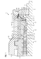
- FIG. 1 a cross section through a steam turbine 1 is shown.
- the steam turbine 1 has an outer housing 2 and an inner housing 3.
- the inner housing 3 and the outer housing 2 have a live steam supply channel, which in the FIG. 2 will be described in more detail.
- a rotor 5 having a thrust balance piston 4 is rotatably mounted inside the inner casing 3.
- the rotor 5 comprises a plurality of rotor blades 7.
- the inner casing 3 has a plurality of stator blades 8.
- the flow channel 9 comprises a plurality of blade stages, each of a series of blades 7 and a number of guide vanes 8 are formed.
- Fresh steam flows into an inflow opening 10 via the main steam supply duct and flows from there in a flow direction 11 through the flow duct 9, which runs essentially parallel to the axis of rotation 6.
- the live steam expands and cools down. Thermal energy is converted into rotational energy.
- the rotor 5 is set in a rotational movement and can, for example, drive a generator for generating electrical energy.
- the thrust balance piston 4 is formed such that a thrust balance piston antechamber 12 is formed and subjected to a defined pressure.
- a thrust balance piston antechamber 12 By supplying steam of a certain pressure in the thrust balance piston antechamber 12 creates a counterforce, which counteracts a thrust 13 of the blade path.
- the live steam supply is represented symbolically by the arrow 13a.
- the live steam usually has temperature values of, for example, up to 625 ° C and a pressure of up to 350bar.
- the live steam flows in the flow direction 11 through the flow channel 9. After a vane stage, the steam flows into the thrust balance vane 12 via a connection comprising a feed duct 14, a first pressure chamber 15 and a supply duct 16.
- the steam flows into the first pressure space 15 between the inner housing 3 via a feed channel 14, which is designed as a communicating tube between a first pressure chamber 15 between the inner housing 3 and the outer housing 2 and the flow channel 9 according to a blade stage and the outer housing 2.
- this first pressure chamber 15 there is a pressure of p 1 .
- the vapor located in the first pressure chamber 15 between the inner housing 3 and the outer housing 2 now has lower temperature and pressure values.
- This steam flows through a supply channel 16, which is formed as a communicating tube between the first pressure chamber 15 and the thrust balance piston antechamber 12.
- the thrust balance piston antechamber 12 is disposed in an axial direction 17 between the thrust balance piston 4 and the inner housing 3.
- the Schubaus GmbHskolbenvorraum 12 may also be referred to as the fourth pressure chamber. In this fourth pressure chamber there is a pressure p 1 .
- a smaller part flows as a leak vapor into a leak-sealing chamber 18.
- the leakage steam flows essentially in an opposite direction 19.
- the opposite direction 19 is opposite to Flow direction 11 aligned.
- the leakage steam flows through a cross-return passage 20, which is a communicating tube between the sealing space 18 formed between the rotor 5 and the housing 3 and a vane-shaped inflow space 26 into the flow passage 9.
- the cross-return passage 20 is in this case from the sealing chamber 18 to the first pressure chamber 15 is substantially perpendicular, after a deflection 21 substantially parallel and after a second deflection 22 substantially perpendicular to the flow direction 11, but without connecting the sealing chamber 18 with the first pressure chamber 15.
- the inner housing 3 and the outer housing 2 may be formed with an overload introduction not shown in detail.
- the overload discharge 23 external steam flows through a separate inflow.
- the feed passage 14 is connected to the flow passage 9 downstream of a return scoop step 24 and the cross return passage 20 is connected to the flow passage 9 downstream of a cross return scoop step 25.
- the cross recirculation vane stage 25 is hereby arranged in the flow direction 11 of the flow channel 9 with regard to expansion of the vapor downstream of the recirculation vane stage 24.
- the recycle vane stage 24 is the fourth vane stage and the cross recycle vane stage 25 is the fifth vane stage.
- a seal 27 is disposed in the region of the thrust balance piston 4.
- This seal 27 is expediently designed, for example, as a piston ring and arranged in a groove 28 in the inner housing 3.
- the seal 27 thereby separates the first pressure chamber 15 from a third pressure chamber 29.
- In the third pressure chamber 29 there is a pressure p 3 .
- the pressure p 3 may be approximately equal to the pressure p 1 .
- the third pressure chamber 29 is limited by a further seal 30.
- the further seal 30 is arranged between the inner housing 3 and the outer housing 2 and separates the third pressure chamber 29 from the fourth pressure chamber 31, in which the pressure p 4 prevails.
- the third pressure chamber 29 is connected via a direct connection 32 with the thrust balance piston antechamber 12.
- the pressure p 2 prevails in the thrust balance piston antechamber, where: p 2 ⁇ p 3 .
- the connection 32 constitutes a fluidic connection and allows vapor, which is in the third pressure chamber 29, to flow into the thrust balance piston antechamber 12.
- the steam located in the fourth pressure chamber 31 opens in the inner housing end region 33 onto a thrust balance piston surface 34 of the thrust balance piston 4.
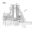
- the FIG. 2 shows a cross section through the steam turbine 1 in section through an inflow 35.
- the inflow 35 comprises a valve diffuser 36. From the valve diffuser 36 live steam flows into the inflow opening 10 and from there, as for FIG. 1 described, through the flow channel 9.
- the in the first pressure chamber 15 zugeströmte vapor may flow in part into a ring cooling passage 37 which is formed between the valve diffuser 36 and the outer housing 2.
- the steam flows via a further cooling channel 39 in the outer housing 2 to the third pressure chamber 29. From the third pressure chamber 29, the steam flows via the connection 32 into the thrust balance piston antechamber 12.
- valve connection 40 Since the pressure p 1 > p 3 > p 4 , This creates a targeted forced flow through this component area, which advantageously cools the valve connection 40. Thus, effective cooling of the valve connection 40 is possible without using external cooling steam.
- the valve diffuser 36 is in this case arranged sealingly against the inner housing 3.
- contactless sealing elements such as e.g. Arranged sealing strips, which realize a pressure reduction and a separation of the pressure chambers.
Priority Applications (7)
| Application Number | Priority Date | Filing Date | Title |
|---|---|---|---|
| EP11176574A EP2554789A1 (de) | 2011-08-04 | 2011-08-04 | Dampfturbine umfassend einen Schubausgleichskolben |
| JP2014523320A JP5756886B2 (ja) | 2011-08-04 | 2012-08-01 | スラストバランスピストンを備えている蒸気タービン |
| PCT/EP2012/065065 WO2013017634A1 (de) | 2011-08-04 | 2012-08-01 | Dampfturbine umfassend einen schubausgleichskolben |
| CN201280038308.4A CN103717838B (zh) | 2011-08-04 | 2012-08-01 | 包括推力平衡活塞的蒸汽轮机 |
| IN164DEN2014 IN2014DN00164A (ja) | 2011-08-04 | 2012-08-01 | |
| EP12743152.6A EP2718545B1 (de) | 2011-08-04 | 2012-08-01 | Dampfturbine umfassend einen schubausgleichskolben |
| US14/236,396 US20140199161A1 (en) | 2011-08-04 | 2012-08-01 | Steam turbine comprising a thrust balance piston |
Applications Claiming Priority (1)
| Application Number | Priority Date | Filing Date | Title |
|---|---|---|---|
| EP11176574A EP2554789A1 (de) | 2011-08-04 | 2011-08-04 | Dampfturbine umfassend einen Schubausgleichskolben |
Publications (1)
| Publication Number | Publication Date |
|---|---|
| EP2554789A1 true EP2554789A1 (de) | 2013-02-06 |
Family
ID=45002221
Family Applications (2)
| Application Number | Title | Priority Date | Filing Date |
|---|---|---|---|
| EP11176574A Withdrawn EP2554789A1 (de) | 2011-08-04 | 2011-08-04 | Dampfturbine umfassend einen Schubausgleichskolben |
| EP12743152.6A Not-in-force EP2718545B1 (de) | 2011-08-04 | 2012-08-01 | Dampfturbine umfassend einen schubausgleichskolben |
Family Applications After (1)
| Application Number | Title | Priority Date | Filing Date |
|---|---|---|---|
| EP12743152.6A Not-in-force EP2718545B1 (de) | 2011-08-04 | 2012-08-01 | Dampfturbine umfassend einen schubausgleichskolben |
Country Status (6)
| Country | Link |
|---|---|
| US (1) | US20140199161A1 (ja) |
| EP (2) | EP2554789A1 (ja) |
| JP (1) | JP5756886B2 (ja) |
| CN (1) | CN103717838B (ja) |
| IN (1) | IN2014DN00164A (ja) |
| WO (1) | WO2013017634A1 (ja) |
Cited By (3)
| Publication number | Priority date | Publication date | Assignee | Title |
|---|---|---|---|---|
| EP2987952A1 (de) * | 2014-08-20 | 2016-02-24 | Siemens Aktiengesellschaft | Dampfturbine und Verfahren zum Betrieb einer Dampfturbine |
| RU2659633C2 (ru) * | 2013-09-30 | 2018-07-03 | Сименс Акциенгезелльшафт | Паровая турбина |
| US20210381394A1 (en) * | 2018-11-06 | 2021-12-09 | Shanghai Electric Power Generation Equipment Co., Ltd. | Steam turbine and method for internally cooling the same |
Families Citing this family (2)
| Publication number | Priority date | Publication date | Assignee | Title |
|---|---|---|---|---|
| US8893499B2 (en) * | 2011-10-20 | 2014-11-25 | Dresser-Rand Company | Advanced super-critical CO2 expander-generator |
| EP3130748A1 (de) * | 2015-08-14 | 2017-02-15 | Siemens Aktiengesellschaft | Rotorkühlung für eine dampfturbine |
Citations (5)
| Publication number | Priority date | Publication date | Assignee | Title |
|---|---|---|---|---|
| US2304994A (en) * | 1941-06-20 | 1942-12-15 | Westinghouse Electric & Mfg Co | Turbine cylinder cooling |
| US2524724A (en) * | 1948-10-07 | 1950-10-03 | Westinghouse Electric Corp | Turbine apparatus |
| US2796231A (en) * | 1954-03-24 | 1957-06-18 | Westinghouse Electric Corp | High pressure steam turbine casing structure |
| EP1624155A1 (de) * | 2004-08-02 | 2006-02-08 | Siemens Aktiengesellschaft | Dampfturbine und Verfahren zum Betrieb einer Dampfturbine |
| EP1780376A1 (de) * | 2005-10-31 | 2007-05-02 | Siemens Aktiengesellschaft | Dampfturbine |
Family Cites Families (6)
| Publication number | Priority date | Publication date | Assignee | Title |
|---|---|---|---|---|
| US4661043A (en) * | 1985-10-23 | 1987-04-28 | Westinghouse Electric Corp. | Steam turbine high pressure vent and seal system |
| US6036433A (en) * | 1998-06-29 | 2000-03-14 | General Electric Co. | Method of balancing thrust loads in steam turbines |
| EP1035301A1 (de) * | 1999-03-08 | 2000-09-13 | Asea Brown Boveri AG | Ausgleichskolben für den axialen Schubausgleich einer Welle von einer Turbine |
| JP4455254B2 (ja) * | 2004-09-30 | 2010-04-21 | 株式会社東芝 | 蒸気タービンおよびこれを備える蒸気タービンプラント |
| DE102008022966B4 (de) * | 2008-05-09 | 2014-12-24 | Siemens Aktiengesellschaft | Rotationsmaschine |
| EP2410128A1 (de) * | 2010-07-21 | 2012-01-25 | Siemens Aktiengesellschaft | Interne Kühlung für eine Strömungsmaschine |
-
2011
- 2011-08-04 EP EP11176574A patent/EP2554789A1/de not_active Withdrawn
-
2012
- 2012-08-01 IN IN164DEN2014 patent/IN2014DN00164A/en unknown
- 2012-08-01 JP JP2014523320A patent/JP5756886B2/ja not_active Expired - Fee Related
- 2012-08-01 WO PCT/EP2012/065065 patent/WO2013017634A1/de active Application Filing
- 2012-08-01 EP EP12743152.6A patent/EP2718545B1/de not_active Not-in-force
- 2012-08-01 US US14/236,396 patent/US20140199161A1/en not_active Abandoned
- 2012-08-01 CN CN201280038308.4A patent/CN103717838B/zh not_active Expired - Fee Related
Patent Citations (5)
| Publication number | Priority date | Publication date | Assignee | Title |
|---|---|---|---|---|
| US2304994A (en) * | 1941-06-20 | 1942-12-15 | Westinghouse Electric & Mfg Co | Turbine cylinder cooling |
| US2524724A (en) * | 1948-10-07 | 1950-10-03 | Westinghouse Electric Corp | Turbine apparatus |
| US2796231A (en) * | 1954-03-24 | 1957-06-18 | Westinghouse Electric Corp | High pressure steam turbine casing structure |
| EP1624155A1 (de) * | 2004-08-02 | 2006-02-08 | Siemens Aktiengesellschaft | Dampfturbine und Verfahren zum Betrieb einer Dampfturbine |
| EP1780376A1 (de) * | 2005-10-31 | 2007-05-02 | Siemens Aktiengesellschaft | Dampfturbine |
Cited By (8)
| Publication number | Priority date | Publication date | Assignee | Title |
|---|---|---|---|---|
| RU2659633C2 (ru) * | 2013-09-30 | 2018-07-03 | Сименс Акциенгезелльшафт | Паровая турбина |
| US10227873B2 (en) | 2013-09-30 | 2019-03-12 | Siemens Aktiengesellschaft | Steam turbine |
| EP2987952A1 (de) * | 2014-08-20 | 2016-02-24 | Siemens Aktiengesellschaft | Dampfturbine und Verfahren zum Betrieb einer Dampfturbine |
| WO2016026880A1 (de) * | 2014-08-20 | 2016-02-25 | Siemens Aktiengesellschaft | Dampfturbine und verfahren zum betrieb einer dampfturbine |
| US10436030B2 (en) | 2014-08-20 | 2019-10-08 | Siemens Aktiengesellschaft | Steam turbine and method for operating a steam turbine |
| US20210381394A1 (en) * | 2018-11-06 | 2021-12-09 | Shanghai Electric Power Generation Equipment Co., Ltd. | Steam turbine and method for internally cooling the same |
| EP3879078A4 (en) * | 2018-11-06 | 2022-08-31 | Shanghai Electric Power Generation Equipment Co., Ltd. | STEAM TURBINE AND ITS INTERNAL COOLING PROCESS |
| US11746674B2 (en) | 2018-11-06 | 2023-09-05 | Shanghai Electric Power Generation Equipment Co., Ltd. | Steam turbine and method for internally cooling the same |
Also Published As
| Publication number | Publication date |
|---|---|
| WO2013017634A1 (de) | 2013-02-07 |
| EP2718545B1 (de) | 2016-03-02 |
| CN103717838A (zh) | 2014-04-09 |
| JP2014521872A (ja) | 2014-08-28 |
| IN2014DN00164A (ja) | 2015-05-22 |
| US20140199161A1 (en) | 2014-07-17 |
| EP2718545A1 (de) | 2014-04-16 |
| CN103717838B (zh) | 2016-02-17 |
| JP5756886B2 (ja) | 2015-07-29 |
Similar Documents
| Publication | Publication Date | Title |
|---|---|---|
| EP2596213B1 (de) | Dampfturbine mit einer internen kühlung | |
| EP1774140B1 (de) | Dampfturbine und verfahren zum betrieb einer dampfturbine | |
| DE60203959T2 (de) | Luftgekühltes Abgasgehäuse für eine Gasturbine | |
| EP2824282A1 (de) | Gasturbine mit Hochdruckturbinenkühlsystem | |
| EP2718545B1 (de) | Dampfturbine umfassend einen schubausgleichskolben | |
| CH708326A2 (de) | Gasturbinen-Deckbandkühlung. | |
| EP3130748A1 (de) | Rotorkühlung für eine dampfturbine | |
| CH702000A2 (de) | Wirbelkammern zur Spaltströmungssteuerung. | |
| DE102015122928A1 (de) | Gasturbinendichtung | |
| EP2719869A1 (de) | Axiale Abdichtung in einer Gehäusestruktur für eine Strömungsmaschine | |
| DE102017110055A1 (de) | Zentraler Zwischenkanal, der äußere Wände hinter einem Vorderkantenkanal eines Schaufelblattes überbrückt | |
| EP2802748B1 (de) | Strömungsmaschine mit schraubenkühlung | |
| EP3155226B1 (de) | Dampfturbine und verfahren zum betrieb einer dampfturbine | |
| DE102012208263A1 (de) | Verdichtervorrichtung für eine Turbomaschine | |
| EP2823154B1 (de) | Kühlmittelüberbrückungsleitung, zugehörige turbinenschaufel, gasturbine und kraftwerksanlage | |
| DE102016202833A1 (de) | Gasturbine mit Kühlung über die hintere Hohlwelle | |
| DE102014117263A1 (de) | Dampfturbine und Verfahren zur Montage derselben | |
| EP2598724B1 (de) | Dampfturbine sowie verfahren zum kühlen einer solchen | |
| DE102012206090A1 (de) | Axialverdichter einer Turbomaschine | |
| DE102006010863B4 (de) | Turbomaschine, insbesondere Verdichter | |
| EP3183426B1 (de) | Kontrollierte kühlung von turbinenwellen | |
| EP3172407B1 (de) | Gasturbine mit einer kühlung der letzten turbinenstufe | |
| EP1598537B1 (de) | Dampfturbinen-Körper, Verfahren zum Kühlen einer Dampfturbine sowie Verwendung | |
| EP1895094B1 (de) | Drallgekühlte Rotor-Schweissnaht | |
| DE102016203731A1 (de) | Dampfturbine |
Legal Events
| Date | Code | Title | Description |
|---|---|---|---|
| PUAI | Public reference made under article 153(3) epc to a published international application that has entered the european phase |
Free format text: ORIGINAL CODE: 0009012 |
|
| AK | Designated contracting states |
Kind code of ref document: A1 Designated state(s): AL AT BE BG CH CY CZ DE DK EE ES FI FR GB GR HR HU IE IS IT LI LT LU LV MC MK MT NL NO PL PT RO RS SE SI SK SM TR |
|
| AX | Request for extension of the european patent |
Extension state: BA ME |
|
| RAP1 | Party data changed (applicant data changed or rights of an application transferred) |
Owner name: SIEMENS AKTIENGESELLSCHAFT |
|
| STAA | Information on the status of an ep patent application or granted ep patent |
Free format text: STATUS: THE APPLICATION IS DEEMED TO BE WITHDRAWN |
|
| 18D | Application deemed to be withdrawn |
Effective date: 20130807 |