EP2554352A1 - Verfahren zur Herstellung eines hinterspritzten Formteils - Google Patents
Verfahren zur Herstellung eines hinterspritzten Formteils Download PDFInfo
- Publication number
- EP2554352A1 EP2554352A1 EP12179243A EP12179243A EP2554352A1 EP 2554352 A1 EP2554352 A1 EP 2554352A1 EP 12179243 A EP12179243 A EP 12179243A EP 12179243 A EP12179243 A EP 12179243A EP 2554352 A1 EP2554352 A1 EP 2554352A1
- Authority
- EP
- European Patent Office
- Prior art keywords
- die
- insert
- edge
- tool
- cavity
- Prior art date
- Legal status (The legal status is an assumption and is not a legal conclusion. Google has not performed a legal analysis and makes no representation as to the accuracy of the status listed.)
- Granted
Links
Images

Classifications
-
- B—PERFORMING OPERATIONS; TRANSPORTING
- B29—WORKING OF PLASTICS; WORKING OF SUBSTANCES IN A PLASTIC STATE IN GENERAL
- B29C—SHAPING OR JOINING OF PLASTICS; SHAPING OF MATERIAL IN A PLASTIC STATE, NOT OTHERWISE PROVIDED FOR; AFTER-TREATMENT OF THE SHAPED PRODUCTS, e.g. REPAIRING
- B29C45/00—Injection moulding, i.e. forcing the required volume of moulding material through a nozzle into a closed mould; Apparatus therefor
- B29C45/14—Injection moulding, i.e. forcing the required volume of moulding material through a nozzle into a closed mould; Apparatus therefor incorporating preformed parts or layers, e.g. injection moulding around inserts or for coating articles
- B29C45/1418—Injection moulding, i.e. forcing the required volume of moulding material through a nozzle into a closed mould; Apparatus therefor incorporating preformed parts or layers, e.g. injection moulding around inserts or for coating articles the inserts being deformed or preformed, e.g. by the injection pressure
- B29C45/14196—Injection moulding, i.e. forcing the required volume of moulding material through a nozzle into a closed mould; Apparatus therefor incorporating preformed parts or layers, e.g. injection moulding around inserts or for coating articles the inserts being deformed or preformed, e.g. by the injection pressure the inserts being positioned around an edge of the injected part
Definitions
- the invention relates to a method for producing a molded part by means of a tool, which has a die and a mandrel, wherein in a first step, a behind injecting or behind foaming insert is inserted into the die, so that an edge of the insert over an edge of the die or a die-side slide or frame, and in a second step, the tool is closed so that a cavity is formed between the mandrel and the die, wherein in a third step, the cavity is filled with an injection molding material or a foam.
- the invention relates to a molded part with a behind injected or behind foamed insert.
- insert in this document means any insertable into the die and behind sprayable materials, especially decorative materials, fabrics, films, etc. understood.
- injection molding is understood in this document also Banlhnetician and extrusion.
- a method of the type mentioned is, for example, from EP 1 144 177 B1 known.
- an injection molding tool is used, which has a die and a mold core, which form a subsequently referred to as a cavity cavity.
- an insert for example, a decorative material, inserted, which is injected by filling the cavity with plastic behind, so that the inserted material is pressed against the Kavticianswand.
- the plastic is injected at low pressure.
- the injection mold is initially not completely closed, but remains slightly open, for example, 2 to 10 mm.
- a so-called dipping edge gap is provided.
- the upper material which is inserted in the matrix before the injection molding process, extends into the dipping edge gap and, when the injection molding tool is completely closed, which occurs during the injection of plastic, trapped in the dipping edge gap.
- the main problem in the back injection of inserts is distinguished in diving edge play. This is necessary for the venting of the tool cavity. If the dipping edge play is too large, the plastic overspreads the insert in the folding area and prevents or damages the subsequent folding of the insert. If the dipping edge clearance is too short, the insertion of the punch will cause the insert to be compressed so that wrinkles form in the visible area of the component.
- a disadvantage of the known embodiments it is especially because a complex post-processing is required, since the depositors are on the edge overhanging and thus must be everted in a post-processing step and attached or trimmed. This post-processing is expensive and time-consuming and also requires certain component qualities to be executed without damage.
- the solution according to the invention makes it possible to carry out no post-processing steps on the resulting components during the back-injection of inserts. Since the protruding decorative foil is bent and fastened directly in the tool. By bending over by means of the mold core, the edge of the insert part comes to rest within the cavity when the injection mold is closed. With the solution according to the invention, it is possible to perform transcripts, for example, in the angle of 90 ° and 180 ° directly in the injection mold. Also, the above-mentioned problem with the diving edge clearance is solved by the invention, since the dipping edge clearance can be chosen a bit larger, because if the plastic overflows a few millimeters, this no longer matters because the post is eliminated.
- a side effect of the solution according to the invention is also that foil clips for fixing the insert in the tool are omitted. Until now it was usual to pull the film over the slide and fasten. Since the foil is now cut off, the clamps also fall away. The foil holds by its form in the matrix.
- the insert is inserted so that its protruding edge encloses an angle greater than zero degrees with a surface of the die or the die-side slide or the die-side frame.
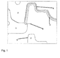
- Fig. 1 shows a molded part 3 with a folded over by 90 ° Umbugkante.
- the molded body 3 is produced by means of an injection molding tool which has a die 7 and a mandrel 2.
- an insert member 4 which is to be sprayed behind or behind the foaming insert 4 is inserted into the die 7.
- an edge 6 of the insert over an edge of the die or a die-side slide 1 or frame over.
- the edge 6 is also referred to as depositor excess 6.
- the slider 1 surrounds the visible edge and fixes the insert 4 so that the depositor excess 6 is slightly pressed against the mandrel 2.
- the insert 4 can be tailored so that a small depositor excess 6 protrudes over the slider 1.
- the insert 4 may be trimmed so that the inlay excess 6 projects from the die 7 and encloses an angle greater than zero degrees with the surface of the die 7 or the slider 1 or the frame.
- the material of the insert 4 is a plastic and / or elastic material.
- a material for the insert 4 basically any material can be used which is suitable for a back injection or foaming.
- a second step the tool is closed.
- the depositor excess 6 is bent by the mandrel 2 in the direction of the die 7.
- the mold closing movement of the mandrel 2 moves into the die 7 and bends the depositor excess 6 at a dip edge gap 5.
- the cavity is filled with an injection molding material or a foam.
- the incoming plastic melt front presses the insert 4 and the depositor excess 6 to the corresponding cavity outer walls and thereby forms the radius and the in Fig. 2 achieved 180 ° Umbug achieved.
- the depositor excess 6 does not protrude into the dipping edge gap 5 and is bent in the tool.
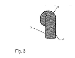
- the insert 4 may in the illustrated example, for example, a surface 8 in the form of a film and an adjoining body made of foam.
Landscapes
- Engineering & Computer Science (AREA)
- Manufacturing & Machinery (AREA)
- Mechanical Engineering (AREA)
- Injection Moulding Of Plastics Or The Like (AREA)
- Moulds For Moulding Plastics Or The Like (AREA)
Abstract
Description
- Die Erfindung betrifft ein Verfahren zum Herstellen eines Formteils mittels eines Werkzeuges, welches eine Matrize und einem Formkern aufweist, wobei in einem ersten Schritt ein zu hinter spritzender oder hinter schäumender Einlegeteil in die Matrize eingelegt wird, sodass eine Kante des Einlegeteils über einen Rand der Matrize oder eines matrizenseitigen Schiebers oder Rahmens übersteht, und in einem zweiten Schritt das Werkzeug geschlossen wird, sodass zwischen dem Formkern und der Matrize eine Kavität gebildet wird, wobei in einem dritten Schritt die Kavität mit einem Spritzgussmaterial oder einem Schaumstoff aufgefüllt wird.
- Weiters betrifft die Erfindung einen Formteil mit einem hinter spritzten oder hinter schäumten Einlegeteil.
- Unter dem Begriff "Einleger", werden in diesem Dokument beliebige in die Matrize einlegbare und hinter spritzbare Materialien, insbesondere Dekormaterialien, Stoffe, Folien, etc. verstanden. Unter dem Begriff "Hinterspritzen" wird in diesem Dokument auch Quellflussprägen und Strangpressen verstanden.
- Ein Verfahren der eingangs genannten Art ist beispielsweise aus der
EP 1 144 177 B1 bekannt geworden. Bei dem bekannten Verfahren kommt ein Spritzgusswerkzeug zum Einsatz, welches eine Matrize und einen Formkern aufweist, die einen in weiterer Folge als Kavität bezeichneten Hohlraum bilden. In das Werkzeug wird ein Einleger, beispielsweise ein Dekormaterial, eingelegt, welches durch Auffüllen der Kavität mit Kunststoff hinter spritzt wird, sodass das eingelegte Material an die Kavitätswand gepresst wird. Um eine Beschädigung des Einlegers zu vermeiden wird der Kunststoff mit geringem Druck eingespritzt. Hierzu ist das Spritzgießwerkzeug zunächst noch nicht vollkommen geschlossen, sondern bleibt geringfügig geöffnet, beispielsweise 2 bis 10 mm. Um zu vermeiden, dass in dieser Position eingespritzter Kunststoff über den Randbereich der Kavität austritt, ist ein sogenannter Tauchkantenspalt vorgesehen. Das vor dem Hinterspritzen in die Matrize eingelegte Obermaterial erstreckt sich in den Tauchkantenspalt hinein und wird beim vollständigen Schließen des Spritzgießwerkzeugs, das während des Einspritzens von Kunststoff erfolgt, im Tauchkantenspalt eingeklemmt. - Das Hauptproblem beim Hinterspritzen von Einlegern zeichnet sich beim Tauchkantenspiel ab. Diese ist für die Entlüftung der Werkzeugkavität notwendig. Ist das Tauchkantenspiel zu groß, so überspritzt der Kunststoff den Einleger im Umbugbereich und verhindert oder beschädigt das nachträgliche Umbugen des Einlegers. Wird das Tauchkantenspiel zu knapp bemessen, wird durch das Einfahren des Stempels der Einleger gestaucht, sodass sich im Sichtbereich des Bauteils Falten bilden.
- Nachteilig an den bekannten Ausführungsformen ist es vor allem, dass eine aufwendige Nachbearbeitung erforderlich ist, da die Einleger am Rand überstehend sind und dadurch in einem Nachbearbeitungsschritt umgebugt und befestigt oder beschnitten werden müssen. Diese Nachbearbeitung ist teuer und zeitaufwendig und fordert auch gewisse Bauteilgüten um beschädigungsfrei ausgeführt zu werden.
- Es ist daher eine Aufgabe der Erfindung, die oben genannten Nachteile zu überwinden.
- Diese Aufgabe wird mit einem Verfahren der eingangs genannten Art erfindungsgemäß dadurch gelöst, dass während des Schließens des Werkzeugs die überstehende Kante von dem Formkern in Richtung der Matrize umgebogen wird.
- Die erfindungsgemäße Lösung ermöglicht es, dass beim Hinterspritzen von Einlegern keine Nachbearbeitungsschritte an den resultierenden Bauteilen durchzuführen sind. Da die überstehende Dekorfolie direkt im Werkzeug umgebugt und befestigt wird. Durch das Umbiegen mittels des Formkerns kommt die Kante des Einlegeteils bei Schließen des Spritzgießwerkzeuges innerhalb der Kavität zu liegen. Mit der erfindungsgemäßen Lösung ist es möglich, Umbüge beispielsweise in den Winkel von 90° und 180° direkt im Spritzgusswerkzeug durchzuführen. Auch das oben angesprochene Problem mit dem Tauchkantenspiel ist durch die Erfindung gelöst, da das Tauchkantenspiel ein bisschen grösser gewählt werden kann, denn falls der Kunststoff einige Millimeter überschießt spielt dies keine Rolle mehr, weil die Nachbearbeitung wegfällt. Ein Nebeneffekt der erfindungsgemäßen Lösung besteht auch darin, dass Folienklemmen zur Fixierung des Einlegers im Werkzeug wegfallen. Bis jetzt war es üblich, die Folie weiter über den Schieber zu ziehen und zu befestigen. Da die Folie nun abgeschnitten wird, fallen auch die Klemmen weg. Die Folie hält durch ihre Form in der Matrize.
- Vorteilhafterweise wird der Einlegeteil so eingelegt wird, dass seine überstehende Kante einen Winkel größer als Null Grad mit einer Oberfläche der Matrize oder des matrizenseitigen Schiebers oder des matrizenseitigen Rahmens einschließt. Durch diese Maßnahme lässt sich auf einfache Weise sicherstellen, dass die Kante des Einlegeteils bei Schließen des Spritzgusswerkzeuges von dem Formteil umgebugt wird.
- Als besonders vorteilhaft hat sich herausgestellt, wenn ein Einlegeteil aus einem elastischen oder plastischen Material verwendet wird. Auf diese Weise lässt sich ein Abstehen des Einlegerüberschusses über die Matrize bewerkstelligen.
- Die oben genannte Aufgabe lässt sich auch mit einem Formteil der eingangs genannten Art lösen, welcher es nach dem erfindungsgemäßen Verfahren hergestellt ist.
- Zum besseren Verständnis der Erfindung wird diese anhand der nachfolgenden Figuren näher erläutert.
- Es zeigen jeweils in stark schematisch vereinfachter Darstellung:
-
Fig. 1 ein Spritzgusswerkzeug in einem geöffneten Zustand mit einem Formkörper mit einer um 90° umgebogenen Umbugkante -
Fig. 2 das Spritzgusswerkzeug ausFig. 1 mit einem Formteil mit einer um 180° umgebogenen Umbugkante und -
Fig. 3 ein Detail eines erfindungsgemäßen Formteils mit in einem Spritzgusswerkzeug umgebugten Umbug. - Einführend sei festgehalten, dass in den unterschiedlich beschriebenen Ausführungsformen gleiche Teile mit gleichen Bezugszeichen bzw. gleichen Bauteilbezeichnungen versehen werden, wobei die in der gesamten Beschreibung enthaltenen Offenbarungen sinngemäß auf gleiche Teile mit gleichen Bezugszeichen bzw. gleichen Bauteilbezeichnungen übertragen werden können. Auch sind die in der Beschreibung gewählten Lageangaben, wie z.B. oben, unten, seitlich usw. auf die unmittelbar beschriebene sowie dargestellte Figur bezogen und sind bei einer Lageänderung sinngemäß auf die neue Lage zu übertragen. Weiters können auch Einzelmerkmale oder Merkmalskombinationen aus den gezeigten und beschriebenen unterschiedlichen Ausführungsbeispielen für sich eigenständige, erfinderische oder erfindungsgemäße Lösungen darstellen.
- Sämtliche Angaben zu Wertebereichen in gegenständlicher Beschreibung sind so zu verstehen, dass diese beliebige und alle Teilbereiche daraus mit umfassen, z.B. ist die Angabe 1 bis 10 so zu verstehen, dass sämtliche Teilbereiche, ausgehend von der unteren Grenze 1 und der oberen Grenze 10 mitumfasst sind, d.h. sämtliche Teilbereich beginnen mit einer unteren Grenze von 1 oder größer und enden bei einer oberen Grenze von 10 oder weniger, z.B. 1 bis 1,7, oder 3,2 bis 8,1 oder 5,5 bis 10.
-
Fig. 1 zeigt einen Formteil 3 mit einer um 90° umgebogenen Umbugkante. Der Formkörper 3 wird mittels eines Spritzgusswerkzeuges, welches eine Matrize 7 und einen Formkern 2 aufweist, hergestellt. Zur Herstellung des erfindungsgemäßen Formkörpers 3 wird in einem ersten Schritt ein zu hinter spritzender oder hinter schäumender Einlegeteil 4 in die Matrize 7 eingelegt. Hierbei steht eine Kante 6 des Einlegeteils über einen Rand der Matrize oder eines matrizenseitigen Schiebers 1 oder Rahmens über. Im Folgenden wird die Kante 6 auch als Einlegerüberschuss 6 bezeichnet. Der Schieber 1 umrundet die Sichtkante und fixiert den Einlegeteil 4 so, dass der Einlegerüberschuss 6 an den Formkern 2 leicht angedrückt wird. - Um den Umbug im Werkzeug zu erleichtern, kann der Einlegeteil 4 so zugeschnitten werden das ein kleiner Einlegerüberschuss 6 über den Schieber 1 vorsteht. Bevorzugt kann der Einlegeteil 4 so beschnitten werden, dass der Einlegerüberschuss 6 von der Matrize absteht 7 und einen Winkel größer als Null Grad mit der Oberfläche der Matrize 7 oder des Schiebers 1 oder des Rahmens einschließt.
- Als vorteilhaft hat es sich erwiesen, wenn das Material des Einlegeteils 4 ein plastisches und/oder elastisches Material ist. An dieser Stelle sei jedoch darauf hingewiesen, dass als Material für den Einlegeteil 4 grundsätzlich jedes Material verwendet werden kann, welches sich für ein Hinterspritzen oder Hinterschäumen eignet.
- In einem zweiten Schritt wird das Werkzeug geschlossen. Hierbei wird der Einlegerüberschuss 6 von dem Formkern 2 in Richtung der Matrize 7 umgebogen. Während der Werkzeugschliessbewegung fährt der Formkern 2 in die Matrize 7 und bugt den Einlegerüberschuss 6 an einem Tauchkantenspalt 5 um. In einem dritten Schritt wird die Kavität mit einem Spritzgussmaterial oder einem Schaumstoff aufgefüllt.
- Die ankommende Kunststoffschmelzefront drückt den Einlegeteil 4 und den Einlegerüberschuss 6 an die entsprechenden Kavität-Außenwände und formt dadurch den Radius aus und der in
Fig. 2 dargestellte 180° Umbug erzielt. Im Gegensatz zum Stand der Technik ragt der Einlegerüberschuss 6 nicht in den Tauchkantenspalt 5 und wird in dem Werkzeug umgebugt. - Wie aus
Fig. 3 ersichtlich ist, schließt der umgebugte Einlegerüberschuss 6 des fertigen Formteils 3 bündig ab, sodass keine weitere Nachbearbeitung mehr erforderlich ist. Der Einleger 4 kann in dem dargestellten Beispiel beispielsweise eine Oberfläche 8 in Form einer Folie und einen daran anschließenden Körper aus Schaumstoff aufweisen. - Die Ausführungsbeispiele zeigen mögliche Ausführungsvarianten des erfindungsgemäßen Verfahrens bzw. des erfindungsgemäßen Formteils, wobei an dieser Stelle bemerkt sei, dass die Erfindung nicht auf die speziell dargestellten Ausführungsvarianten derselben eingeschränkt ist, sondern vielmehr auch diverse Kombinationen der einzelnen Ausführungsvarianten untereinander möglich sind und diese Variationsmöglichkeit aufgrund der Lehre zum technischen Handeln durch gegenständliche Erfindung im Können des auf diesem technischen Gebiet tätigen Fachmannes liegt. Es sind also auch sämtliche denkbaren Ausführungsvarianten, die durch Kombinationen einzelner Details der dargestellten und beschriebenen Ausführungsvariante möglich sind, vom Schutzumfang mit umfasst.
- Der Ordnung halber sei abschließend darauf hingewiesen, dass zum besseren Verständnis des Aufbaus eines verwendeten Spritzgusswerkzeuges dieses bzw. dessen Bestandteile teilweise nicht maßstäblich und/oder vergrößert und/oder verkleinert dargestellt wurden.
-
- 1
- Schieber
- 2
- Formkern
- 3
- Formteil (Bauteil)
- 4
- Einlegeteil (Enleger)
- 5
- Tauchkantenspalt
- 6
- Kante (Einlegerüberschuss)
- 7
- Matrize
- 8
- Oberfläche des Einlegeteils
Claims (5)
- Verfahren zum Herstellen eines Formteils (3) mittels eines Werkzeuges, welches eine Matrize (7) und einem Formkern (2) aufweist, wobei in einem ersten Schritt ein zu hinterspritzender oder hinterschäumender Einlegeteil (4) in die Matrize (7) eingelegt wird, sodass eine Kante (6) des Einlegeteils (4) über einen Rand der Matrize (7) oder eines matrizenseitigen Schiebers (1) oder Rahmens übersteht, und in einem zweiten Schritt das Werkzeug geschlossen wird, sodass zwischen dem Formkern (2) und der Matrize (7) eine Kavität gebildet wird, wobei in einem dritten Schritt die Kavität mit einem Spritzgussmaterial oder einem Schaumstoff aufgefüllt wird, dadurch gekennzeichnet, dass in Schritt zwei die überstehende Kante (6) von dem Formkern (2) in Richtung der Matrize (7) umgebogen wird.
- Verfahren nach Anspruch 1, dadurch gekennzeichnet, dass der Einlegeteil (14) in Schritt eins so eingelegt wird, dass seine überstehende Kante (6) einen Winkel größer als Null Grad mit einer Oberfläche der Matrize (7) oder des matrizenseitigen Schiebers (1) oder des matrizenseitigen Rahmens einschließt.
- Verfahren nach einem der Ansprüche 1 oder 2, dadurch gekennzeichnet, dass in Schritt eins ein Einlegeteil (14) aus einem elastischen Material verwendet wird.
- Verfahren nach einem der Ansprüche 1 bis 3, dadurch gekennzeichnet, dass in Schritt eins ein Einlegeteil (14) aus einem plastischen Material verwendet wird.
- Formteil (3) mit einem hinterspritzten oder hinterschäumten Einlegeteil (14), dadurch gekennzeichnet, dass es nach einem Verfahren nach einem der Ansprüche 1 bis 4 hergestellt ist.
Applications Claiming Priority (2)
| Application Number | Priority Date | Filing Date | Title |
|---|---|---|---|
| AT11352011 | 2011-08-05 | ||
| ATA1145/2011A AT511735B1 (de) | 2011-08-05 | 2011-08-09 | Verfahren zur herstellung eines hinterspritzten formteils |
Publications (3)
| Publication Number | Publication Date |
|---|---|
| EP2554352A1 true EP2554352A1 (de) | 2013-02-06 |
| EP2554352B1 EP2554352B1 (de) | 2017-03-01 |
| EP2554352B2 EP2554352B2 (de) | 2020-08-19 |
Family
ID=46601703
Family Applications (1)
| Application Number | Title | Priority Date | Filing Date |
|---|---|---|---|
| EP12179243.6A Active EP2554352B2 (de) | 2011-08-05 | 2012-08-03 | Verfahren zur herstellung eines hinterspritzten formteils |
Country Status (2)
| Country | Link |
|---|---|
| EP (1) | EP2554352B2 (de) |
| AT (1) | AT511735B1 (de) |
Cited By (3)
| Publication number | Priority date | Publication date | Assignee | Title |
|---|---|---|---|---|
| EP3178624A1 (de) * | 2015-12-08 | 2017-06-14 | Georg Kaufmann Formenbau AG | Vorrichtung und verfahren zur herstellung von verbundformteilen |
| WO2021156001A1 (de) | 2020-02-03 | 2021-08-12 | Georg Kaufmann Formenbau Ag | Spritzgusswerkzeug und verfahren zur herstellung von formteilen |
| DE102023114876A1 (de) | 2023-06-06 | 2024-12-12 | Audi Aktiengesellschaft | Verfahren zur Herstellung eines Spritzgussbauteils mit Kunststoffmaterialien unterschiedlicher Härte, Interieurbauteil für ein Kraftfahrzeug und Verwendung des Spritzgussbauteils als Recyclingmaterial |
Families Citing this family (1)
| Publication number | Priority date | Publication date | Assignee | Title |
|---|---|---|---|---|
| JP6632094B2 (ja) * | 2017-02-01 | 2020-01-15 | 河西工業株式会社 | 自動車用内装部品 |
Citations (7)
| Publication number | Priority date | Publication date | Assignee | Title |
|---|---|---|---|---|
| DE4127241A1 (de) * | 1991-08-17 | 1993-02-18 | Bayer Ag | Hinterspritzverfahren |
| JPH08156015A (ja) * | 1994-11-29 | 1996-06-18 | Takashimaya Nippatsu Kogyo Kk | 表皮一体合成樹脂成形品の製造方法およびそのための成形型 |
| JPH1177739A (ja) * | 1997-09-10 | 1999-03-23 | Toyo Tire & Rubber Co Ltd | 表皮と樹脂芯体との一体成形方法 |
| EP1144177B1 (de) | 1999-01-28 | 2003-05-28 | Franz Josef Summerer | Spritzgiessvorrichtung zum hinterspritzen eines obermaterials mit kunststoff und verfahren |
| US20030215614A1 (en) * | 2000-06-12 | 2003-11-20 | Hiroaki Yamamoto | Injection co-molding with offset parting line |
| US20080197670A1 (en) * | 2004-06-15 | 2008-08-21 | Johnson Controls Technology Company | Vehicle Component and Method For Making a Vehicle Component |
| US20080237925A1 (en) * | 2004-06-15 | 2008-10-02 | Johnson Controls Technology Company | Vehicle Component and Method For Making a Vehicle Component |
Family Cites Families (11)
| Publication number | Priority date | Publication date | Assignee | Title |
|---|---|---|---|---|
| DE3634596A1 (de) * | 1986-10-10 | 1988-04-21 | Audi Ag | Verfahren und vorrichtung zur herstellung von karosserieteilen in verbundtechnik |
| JP2529991B2 (ja) * | 1988-02-29 | 1996-09-04 | 昭和電工株式会社 | スタンピング成形金型および表皮端部の処理方法 |
| JP2976537B2 (ja) * | 1991-02-07 | 1999-11-10 | 豊田合成株式会社 | 表皮付き成形品の成形方法とその成形に使用する成形型 |
| JP2611593B2 (ja) * | 1991-12-18 | 1997-05-21 | 豊田合成株式会社 | 表皮インモールド成形方法 |
| DE4235769A1 (de) * | 1992-10-23 | 1994-04-28 | Riesselmann & Sohn | Verfahren zur Herstellung eines Kunststoffträgers mit einem Verkleidungselement und danach hergestelltes Teil |
| JP2968682B2 (ja) * | 1993-12-30 | 1999-10-25 | テイ・エス テック株式会社 | 表皮一体成形方法及びその装置 |
| JP2662933B2 (ja) * | 1993-12-30 | 1997-10-15 | 東京シート株式会社 | 表皮一体成形方法 |
| DE4408446A1 (de) * | 1994-03-12 | 1995-09-14 | Otto Deuschle Modell Formenbau | Folienkaschiertes Kunststoff-Formteil sowie Verfahren und Vorrichtung zu dessen Herstellung |
| DE19948155A1 (de) * | 1999-10-06 | 2001-04-12 | Volkswagen Ag | Vorrichtung und Verfahren zur Herstellung eines mit einem Dekor versehenen Formteiles und zum Umbugen und Beschneiden des Dekors im Formwerkzeug |
| DE102006005303B4 (de) * | 2006-02-06 | 2012-07-05 | Franz Josef Summerer | Verfahren zum Anspritzen einer Kunststoffkomponente an ein Kunststoffteil und mehrkomponentiges Kunststoff-Formteil |
| CN101850591A (zh) * | 2009-04-06 | 2010-10-06 | 康准电子科技(昆山)有限公司 | 模内装饰成型方法及模制品 |
-
2011
- 2011-08-09 AT ATA1145/2011A patent/AT511735B1/de not_active IP Right Cessation
-
2012
- 2012-08-03 EP EP12179243.6A patent/EP2554352B2/de active Active
Patent Citations (7)
| Publication number | Priority date | Publication date | Assignee | Title |
|---|---|---|---|---|
| DE4127241A1 (de) * | 1991-08-17 | 1993-02-18 | Bayer Ag | Hinterspritzverfahren |
| JPH08156015A (ja) * | 1994-11-29 | 1996-06-18 | Takashimaya Nippatsu Kogyo Kk | 表皮一体合成樹脂成形品の製造方法およびそのための成形型 |
| JPH1177739A (ja) * | 1997-09-10 | 1999-03-23 | Toyo Tire & Rubber Co Ltd | 表皮と樹脂芯体との一体成形方法 |
| EP1144177B1 (de) | 1999-01-28 | 2003-05-28 | Franz Josef Summerer | Spritzgiessvorrichtung zum hinterspritzen eines obermaterials mit kunststoff und verfahren |
| US20030215614A1 (en) * | 2000-06-12 | 2003-11-20 | Hiroaki Yamamoto | Injection co-molding with offset parting line |
| US20080197670A1 (en) * | 2004-06-15 | 2008-08-21 | Johnson Controls Technology Company | Vehicle Component and Method For Making a Vehicle Component |
| US20080237925A1 (en) * | 2004-06-15 | 2008-10-02 | Johnson Controls Technology Company | Vehicle Component and Method For Making a Vehicle Component |
Cited By (3)
| Publication number | Priority date | Publication date | Assignee | Title |
|---|---|---|---|---|
| EP3178624A1 (de) * | 2015-12-08 | 2017-06-14 | Georg Kaufmann Formenbau AG | Vorrichtung und verfahren zur herstellung von verbundformteilen |
| WO2021156001A1 (de) | 2020-02-03 | 2021-08-12 | Georg Kaufmann Formenbau Ag | Spritzgusswerkzeug und verfahren zur herstellung von formteilen |
| DE102023114876A1 (de) | 2023-06-06 | 2024-12-12 | Audi Aktiengesellschaft | Verfahren zur Herstellung eines Spritzgussbauteils mit Kunststoffmaterialien unterschiedlicher Härte, Interieurbauteil für ein Kraftfahrzeug und Verwendung des Spritzgussbauteils als Recyclingmaterial |
Also Published As
| Publication number | Publication date |
|---|---|
| AT511735A1 (de) | 2013-02-15 |
| AT511735B1 (de) | 2014-12-15 |
| EP2554352B2 (de) | 2020-08-19 |
| EP2554352B1 (de) | 2017-03-01 |
Similar Documents
| Publication | Publication Date | Title |
|---|---|---|
| DE102011050003A1 (de) | Gelochtes Kunststoff-Formteil mit Dekormaterial sowie Vorrichtung und Verfahren zu dessen Herstellung | |
| EP2554352B1 (de) | Verfahren zur herstellung eines hinterspritzten formteils | |
| DE102004040942A1 (de) | Verfahren und Vorrichtung zur Herstellung von Zierteilen | |
| DE102013107991A1 (de) | Verfahren zur endkonturgetreuen Herstellung mechanisch hoch belastbarer Kunststoff-Bauteile | |
| DE102009039116A1 (de) | Vorrichtung zur Herstellung von Faserverbundwerkstoffen | |
| DE102009003981B4 (de) | Vorrichtung und Verfahren zum Spritzgießen eines Kunststoff-Formteils | |
| DE102018100576A1 (de) | Verfahren zur Herstellung eines Formteils mit einer Sichtfläche mit verschiedenen Oberflächenbereichen | |
| EP1144177B1 (de) | Spritzgiessvorrichtung zum hinterspritzen eines obermaterials mit kunststoff und verfahren | |
| DE102017204882A1 (de) | Verfahren zur Herstellung einer Airbagabdeckung und Formwerkzeug | |
| EP2877332B1 (de) | Verfahren zur herstellung eines kunststoffbauteils | |
| DE19834747B4 (de) | Verfahren zur Herstellung einer Kunststoff-Gießhaut | |
| EP3305497B1 (de) | Vorrichtung und verfahren zur herstellung eines hinterspritzten verbundformteils | |
| EP1090731B1 (de) | Vorrichtung und Verfahren zur Herstellung eines mit einem Dekor versehenen Formteiles und zum Umbugen und Beschneiden des Dekors im Formwerkzeug | |
| WO2007128573A1 (de) | Verfahren und vorrichtung zur herstellung eines formteiles mit einer öffnungsnut und formteil | |
| AT509616B1 (de) | Spritzgiessvorrichtung | |
| DE102008005669A1 (de) | Verkleidungsteil für ein Kraftfahrzeug | |
| DE10221239B4 (de) | Vorrichtung und Verfahren zum Hinterspritzen eines Obermaterials mit Kunststoff | |
| DE102008016059A1 (de) | Verfahren zur Herstellung einer Oberflächenschicht | |
| DE102014010573B4 (de) | Werkzeugsystem und Verfahren zur Herstellung eines Verkleidungsteils sowie Verfahren zur Montage des Werkzeugsystems | |
| DE102016123021A1 (de) | Vorrichtung und Verfahren zum Bearbeiten eines Deckels sowie Anordnung für ein Fahrzeugdach und Fahrzeugdach für ein Kraftfahrzeug | |
| EP3383612B1 (de) | Verfahren zur wahlweisen herstellung einer ersten bzw. einer zweiten variante eines mehrschichtigen kunststoffbauteils | |
| DE102015208461A1 (de) | Vorrichtung zur Herstellung faserverstärkter Kunststoffbauteile | |
| DE102013214480A1 (de) | Werkzeug, Platine und Verfahren zum Herstellen von Werkstücken | |
| DE3927039C2 (de) | ||
| EP3224014A1 (de) | Verfahren zur herstellung eines spritzgussbauteils mit einem aus einem organoblech bestehenden einleger, vorrichtung zur durchführung des verfahrens und nach dem verfahren hergestelltes spritzgussbauteil |
Legal Events
| Date | Code | Title | Description |
|---|---|---|---|
| PUAI | Public reference made under article 153(3) epc to a published international application that has entered the european phase |
Free format text: ORIGINAL CODE: 0009012 |
|
| AK | Designated contracting states |
Kind code of ref document: A1 Designated state(s): AL AT BE BG CH CY CZ DE DK EE ES FI FR GB GR HR HU IE IS IT LI LT LU LV MC MK MT NL NO PL PT RO RS SE SI SK SM TR |
|
| AX | Request for extension of the european patent |
Extension state: BA ME |
|
| 17P | Request for examination filed |
Effective date: 20130805 |
|
| RBV | Designated contracting states (corrected) |
Designated state(s): AL AT BE BG CH CY CZ DE DK EE ES FI FR GB GR HR HU IE IS IT LI LT LU LV MC MK MT NL NO PL PT RO RS SE SI SK SM TR |
|
| REG | Reference to a national code |
Ref country code: FR Ref legal event code: EL |
|
| 17Q | First examination report despatched |
Effective date: 20160428 |
|
| GRAP | Despatch of communication of intention to grant a patent |
Free format text: ORIGINAL CODE: EPIDOSNIGR1 |
|
| INTG | Intention to grant announced |
Effective date: 20161004 |
|
| GRAS | Grant fee paid |
Free format text: ORIGINAL CODE: EPIDOSNIGR3 |
|
| GRAA | (expected) grant |
Free format text: ORIGINAL CODE: 0009210 |
|
| AK | Designated contracting states |
Kind code of ref document: B1 Designated state(s): AL AT BE BG CH CY CZ DE DK EE ES FI FR GB GR HR HU IE IS IT LI LT LU LV MC MK MT NL NO PL PT RO RS SE SI SK SM TR |
|
| REG | Reference to a national code |
Ref country code: GB Ref legal event code: FG4D Free format text: NOT ENGLISH |
|
| REG | Reference to a national code |
Ref country code: CH Ref legal event code: EP Ref country code: AT Ref legal event code: REF Ref document number: 870757 Country of ref document: AT Kind code of ref document: T Effective date: 20170315 |
|
| REG | Reference to a national code |
Ref country code: IE Ref legal event code: FG4D Free format text: LANGUAGE OF EP DOCUMENT: GERMAN |
|
| REG | Reference to a national code |
Ref country code: DE Ref legal event code: R096 Ref document number: 502012009619 Country of ref document: DE |
|
| REG | Reference to a national code |
Ref country code: NL Ref legal event code: MP Effective date: 20170301 |
|
| REG | Reference to a national code |
Ref country code: LT Ref legal event code: MG4D |
|
| REG | Reference to a national code |
Ref country code: FR Ref legal event code: PLFP Year of fee payment: 6 |
|
| PG25 | Lapsed in a contracting state [announced via postgrant information from national office to epo] |
Ref country code: LT Free format text: LAPSE BECAUSE OF FAILURE TO SUBMIT A TRANSLATION OF THE DESCRIPTION OR TO PAY THE FEE WITHIN THE PRESCRIBED TIME-LIMIT Effective date: 20170301 Ref country code: FI Free format text: LAPSE BECAUSE OF FAILURE TO SUBMIT A TRANSLATION OF THE DESCRIPTION OR TO PAY THE FEE WITHIN THE PRESCRIBED TIME-LIMIT Effective date: 20170301 Ref country code: HR Free format text: LAPSE BECAUSE OF FAILURE TO SUBMIT A TRANSLATION OF THE DESCRIPTION OR TO PAY THE FEE WITHIN THE PRESCRIBED TIME-LIMIT Effective date: 20170301 Ref country code: NO Free format text: LAPSE BECAUSE OF FAILURE TO SUBMIT A TRANSLATION OF THE DESCRIPTION OR TO PAY THE FEE WITHIN THE PRESCRIBED TIME-LIMIT Effective date: 20170601 Ref country code: GR Free format text: LAPSE BECAUSE OF FAILURE TO SUBMIT A TRANSLATION OF THE DESCRIPTION OR TO PAY THE FEE WITHIN THE PRESCRIBED TIME-LIMIT Effective date: 20170602 |
|
| PG25 | Lapsed in a contracting state [announced via postgrant information from national office to epo] |
Ref country code: ES Free format text: LAPSE BECAUSE OF FAILURE TO SUBMIT A TRANSLATION OF THE DESCRIPTION OR TO PAY THE FEE WITHIN THE PRESCRIBED TIME-LIMIT Effective date: 20170301 Ref country code: SE Free format text: LAPSE BECAUSE OF FAILURE TO SUBMIT A TRANSLATION OF THE DESCRIPTION OR TO PAY THE FEE WITHIN THE PRESCRIBED TIME-LIMIT Effective date: 20170301 Ref country code: LV Free format text: LAPSE BECAUSE OF FAILURE TO SUBMIT A TRANSLATION OF THE DESCRIPTION OR TO PAY THE FEE WITHIN THE PRESCRIBED TIME-LIMIT Effective date: 20170301 Ref country code: RS Free format text: LAPSE BECAUSE OF FAILURE TO SUBMIT A TRANSLATION OF THE DESCRIPTION OR TO PAY THE FEE WITHIN THE PRESCRIBED TIME-LIMIT Effective date: 20170301 Ref country code: BG Free format text: LAPSE BECAUSE OF FAILURE TO SUBMIT A TRANSLATION OF THE DESCRIPTION OR TO PAY THE FEE WITHIN THE PRESCRIBED TIME-LIMIT Effective date: 20170601 |
|
| PG25 | Lapsed in a contracting state [announced via postgrant information from national office to epo] |
Ref country code: NL Free format text: LAPSE BECAUSE OF FAILURE TO SUBMIT A TRANSLATION OF THE DESCRIPTION OR TO PAY THE FEE WITHIN THE PRESCRIBED TIME-LIMIT Effective date: 20170301 |
|
| PG25 | Lapsed in a contracting state [announced via postgrant information from national office to epo] |
Ref country code: SK Free format text: LAPSE BECAUSE OF FAILURE TO SUBMIT A TRANSLATION OF THE DESCRIPTION OR TO PAY THE FEE WITHIN THE PRESCRIBED TIME-LIMIT Effective date: 20170301 Ref country code: RO Free format text: LAPSE BECAUSE OF FAILURE TO SUBMIT A TRANSLATION OF THE DESCRIPTION OR TO PAY THE FEE WITHIN THE PRESCRIBED TIME-LIMIT Effective date: 20170301 Ref country code: CZ Free format text: LAPSE BECAUSE OF FAILURE TO SUBMIT A TRANSLATION OF THE DESCRIPTION OR TO PAY THE FEE WITHIN THE PRESCRIBED TIME-LIMIT Effective date: 20170301 Ref country code: EE Free format text: LAPSE BECAUSE OF FAILURE TO SUBMIT A TRANSLATION OF THE DESCRIPTION OR TO PAY THE FEE WITHIN THE PRESCRIBED TIME-LIMIT Effective date: 20170301 |
|
| PG25 | Lapsed in a contracting state [announced via postgrant information from national office to epo] |
Ref country code: PT Free format text: LAPSE BECAUSE OF FAILURE TO SUBMIT A TRANSLATION OF THE DESCRIPTION OR TO PAY THE FEE WITHIN THE PRESCRIBED TIME-LIMIT Effective date: 20170703 Ref country code: SM Free format text: LAPSE BECAUSE OF FAILURE TO SUBMIT A TRANSLATION OF THE DESCRIPTION OR TO PAY THE FEE WITHIN THE PRESCRIBED TIME-LIMIT Effective date: 20170301 Ref country code: PL Free format text: LAPSE BECAUSE OF FAILURE TO SUBMIT A TRANSLATION OF THE DESCRIPTION OR TO PAY THE FEE WITHIN THE PRESCRIBED TIME-LIMIT Effective date: 20170301 Ref country code: IS Free format text: LAPSE BECAUSE OF FAILURE TO SUBMIT A TRANSLATION OF THE DESCRIPTION OR TO PAY THE FEE WITHIN THE PRESCRIBED TIME-LIMIT Effective date: 20170701 |
|
| REG | Reference to a national code |
Ref country code: DE Ref legal event code: R026 Ref document number: 502012009619 Country of ref document: DE |
|
| PLBI | Opposition filed |
Free format text: ORIGINAL CODE: 0009260 |
|
| 26 | Opposition filed |
Opponent name: FAURECIA INNENRAUM SYSTEME GMBH Effective date: 20171130 |
|
| PLAX | Notice of opposition and request to file observation + time limit sent |
Free format text: ORIGINAL CODE: EPIDOSNOBS2 |
|
| PG25 | Lapsed in a contracting state [announced via postgrant information from national office to epo] |
Ref country code: DK Free format text: LAPSE BECAUSE OF FAILURE TO SUBMIT A TRANSLATION OF THE DESCRIPTION OR TO PAY THE FEE WITHIN THE PRESCRIBED TIME-LIMIT Effective date: 20170301 |
|
| PG25 | Lapsed in a contracting state [announced via postgrant information from national office to epo] |
Ref country code: SI Free format text: LAPSE BECAUSE OF FAILURE TO SUBMIT A TRANSLATION OF THE DESCRIPTION OR TO PAY THE FEE WITHIN THE PRESCRIBED TIME-LIMIT Effective date: 20170301 |
|
| PG25 | Lapsed in a contracting state [announced via postgrant information from national office to epo] |
Ref country code: MC Free format text: LAPSE BECAUSE OF FAILURE TO SUBMIT A TRANSLATION OF THE DESCRIPTION OR TO PAY THE FEE WITHIN THE PRESCRIBED TIME-LIMIT Effective date: 20170301 |
|
| PLBB | Reply of patent proprietor to notice(s) of opposition received |
Free format text: ORIGINAL CODE: EPIDOSNOBS3 |
|
| REG | Reference to a national code |
Ref country code: IE Ref legal event code: MM4A |
|
| REG | Reference to a national code |
Ref country code: BE Ref legal event code: MM Effective date: 20170831 |
|
| REG | Reference to a national code |
Ref country code: FR Ref legal event code: PLFP Year of fee payment: 7 |
|
| PG25 | Lapsed in a contracting state [announced via postgrant information from national office to epo] |
Ref country code: LU Free format text: LAPSE BECAUSE OF NON-PAYMENT OF DUE FEES Effective date: 20170803 |
|
| PG25 | Lapsed in a contracting state [announced via postgrant information from national office to epo] |
Ref country code: IE Free format text: LAPSE BECAUSE OF NON-PAYMENT OF DUE FEES Effective date: 20170803 |
|
| PG25 | Lapsed in a contracting state [announced via postgrant information from national office to epo] |
Ref country code: BE Free format text: LAPSE BECAUSE OF NON-PAYMENT OF DUE FEES Effective date: 20170831 |
|
| PG25 | Lapsed in a contracting state [announced via postgrant information from national office to epo] |
Ref country code: MT Free format text: LAPSE BECAUSE OF FAILURE TO SUBMIT A TRANSLATION OF THE DESCRIPTION OR TO PAY THE FEE WITHIN THE PRESCRIBED TIME-LIMIT Effective date: 20170301 |
|
| REG | Reference to a national code |
Ref country code: AT Ref legal event code: MM01 Ref document number: 870757 Country of ref document: AT Kind code of ref document: T Effective date: 20170803 |
|
| PG25 | Lapsed in a contracting state [announced via postgrant information from national office to epo] |
Ref country code: AT Free format text: LAPSE BECAUSE OF NON-PAYMENT OF DUE FEES Effective date: 20170803 |
|
| REG | Reference to a national code |
Ref country code: DE Ref legal event code: R082 Ref document number: 502012009619 Country of ref document: DE Representative=s name: ABP BURGER RECHTSANWALTSGESELLSCHAFT MBH, DE |
|
| PG25 | Lapsed in a contracting state [announced via postgrant information from national office to epo] |
Ref country code: HU Free format text: LAPSE BECAUSE OF FAILURE TO SUBMIT A TRANSLATION OF THE DESCRIPTION OR TO PAY THE FEE WITHIN THE PRESCRIBED TIME-LIMIT; INVALID AB INITIO Effective date: 20120803 |
|
| PLBP | Opposition withdrawn |
Free format text: ORIGINAL CODE: 0009264 |
|
| PG25 | Lapsed in a contracting state [announced via postgrant information from national office to epo] |
Ref country code: CY Free format text: LAPSE BECAUSE OF NON-PAYMENT OF DUE FEES Effective date: 20170301 |
|
| PG25 | Lapsed in a contracting state [announced via postgrant information from national office to epo] |
Ref country code: MK Free format text: LAPSE BECAUSE OF FAILURE TO SUBMIT A TRANSLATION OF THE DESCRIPTION OR TO PAY THE FEE WITHIN THE PRESCRIBED TIME-LIMIT Effective date: 20170301 |
|
| PG25 | Lapsed in a contracting state [announced via postgrant information from national office to epo] |
Ref country code: TR Free format text: LAPSE BECAUSE OF FAILURE TO SUBMIT A TRANSLATION OF THE DESCRIPTION OR TO PAY THE FEE WITHIN THE PRESCRIBED TIME-LIMIT Effective date: 20170301 |
|
| PUAH | Patent maintained in amended form |
Free format text: ORIGINAL CODE: 0009272 |
|
| STAA | Information on the status of an ep patent application or granted ep patent |
Free format text: STATUS: PATENT MAINTAINED AS AMENDED |
|
| PG25 | Lapsed in a contracting state [announced via postgrant information from national office to epo] |
Ref country code: AL Free format text: LAPSE BECAUSE OF FAILURE TO SUBMIT A TRANSLATION OF THE DESCRIPTION OR TO PAY THE FEE WITHIN THE PRESCRIBED TIME-LIMIT Effective date: 20170301 |
|
| REG | Reference to a national code |
Ref country code: CH Ref legal event code: AELC |
|
| 27A | Patent maintained in amended form |
Effective date: 20200819 |
|
| AK | Designated contracting states |
Kind code of ref document: B2 Designated state(s): AL AT BE BG CH CY CZ DE DK EE ES FI FR GB GR HR HU IE IS IT LI LT LU LV MC MK MT NL NO PL PT RO RS SE SI SK SM TR |
|
| REG | Reference to a national code |
Ref country code: DE Ref legal event code: R102 Ref document number: 502012009619 Country of ref document: DE |
|
| PGFP | Annual fee paid to national office [announced via postgrant information from national office to epo] |
Ref country code: CH Payment date: 20220818 Year of fee payment: 11 |
|
| PGFP | Annual fee paid to national office [announced via postgrant information from national office to epo] |
Ref country code: IT Payment date: 20230609 Year of fee payment: 12 |
|
| PGFP | Annual fee paid to national office [announced via postgrant information from national office to epo] |
Ref country code: GB Payment date: 20230817 Year of fee payment: 12 |
|
| PGFP | Annual fee paid to national office [announced via postgrant information from national office to epo] |
Ref country code: FR Payment date: 20230810 Year of fee payment: 12 |
|
| REG | Reference to a national code |
Ref country code: CH Ref legal event code: PL |
|
| PG25 | Lapsed in a contracting state [announced via postgrant information from national office to epo] |
Ref country code: CH Free format text: LAPSE BECAUSE OF NON-PAYMENT OF DUE FEES Effective date: 20230831 |
|
| GBPC | Gb: european patent ceased through non-payment of renewal fee |
Effective date: 20240803 |
|
| PG25 | Lapsed in a contracting state [announced via postgrant information from national office to epo] |
Ref country code: GB Free format text: LAPSE BECAUSE OF NON-PAYMENT OF DUE FEES Effective date: 20240803 |
|
| PG25 | Lapsed in a contracting state [announced via postgrant information from national office to epo] |
Ref country code: IT Free format text: LAPSE BECAUSE OF NON-PAYMENT OF DUE FEES Effective date: 20240803 |
|
| PG25 | Lapsed in a contracting state [announced via postgrant information from national office to epo] |
Ref country code: FR Free format text: LAPSE BECAUSE OF NON-PAYMENT OF DUE FEES Effective date: 20240831 |
|
| PGFP | Annual fee paid to national office [announced via postgrant information from national office to epo] |
Ref country code: DE Payment date: 20250820 Year of fee payment: 14 |