EP2553933B1 - Cartes de disparité en 3d - Google Patents
Cartes de disparité en 3d Download PDFInfo
- Publication number
- EP2553933B1 EP2553933B1 EP11726942.3A EP11726942A EP2553933B1 EP 2553933 B1 EP2553933 B1 EP 2553933B1 EP 11726942 A EP11726942 A EP 11726942A EP 2553933 B1 EP2553933 B1 EP 2553933B1
- Authority
- EP
- European Patent Office
- Prior art keywords
- disparity
- resolution
- image
- disparity value
- video
- Prior art date
- Legal status (The legal status is an assumption and is not a legal conclusion. Google has not performed a legal analysis and makes no representation as to the accuracy of the status listed.)
- Active
Links
- 238000000034 method Methods 0.000 claims description 29
- 238000012545 processing Methods 0.000 description 44
- 230000005540 biological transmission Effects 0.000 description 37
- 238000006243 chemical reaction Methods 0.000 description 20
- 238000001914 filtration Methods 0.000 description 14
- 238000005070 sampling Methods 0.000 description 13
- 230000008901 benefit Effects 0.000 description 10
- 230000000694 effects Effects 0.000 description 10
- 238000010586 diagram Methods 0.000 description 9
- 210000001747 pupil Anatomy 0.000 description 6
- 238000012937 correction Methods 0.000 description 4
- 238000004891 communication Methods 0.000 description 3
- 239000013598 vector Substances 0.000 description 3
- 239000000969 carrier Substances 0.000 description 2
- 230000006870 function Effects 0.000 description 2
- 229920001690 polydopamine Polymers 0.000 description 2
- 230000002123 temporal effect Effects 0.000 description 2
- 230000000007 visual effect Effects 0.000 description 2
- 238000012952 Resampling Methods 0.000 description 1
- 238000009825 accumulation Methods 0.000 description 1
- 238000013459 approach Methods 0.000 description 1
- 210000004556 brain Anatomy 0.000 description 1
- 230000000295 complement effect Effects 0.000 description 1
- 238000006073 displacement reaction Methods 0.000 description 1
- 238000013213 extrapolation Methods 0.000 description 1
- 238000003780 insertion Methods 0.000 description 1
- 230000037431 insertion Effects 0.000 description 1
- 238000004519 manufacturing process Methods 0.000 description 1
- 230000003287 optical effect Effects 0.000 description 1
- 230000008520 organization Effects 0.000 description 1
- 238000005192 partition Methods 0.000 description 1
- 230000008447 perception Effects 0.000 description 1
- 238000009877 rendering Methods 0.000 description 1
- 238000001228 spectrum Methods 0.000 description 1
Images


Classifications
-
- H—ELECTRICITY
- H04—ELECTRIC COMMUNICATION TECHNIQUE
- H04N—PICTORIAL COMMUNICATION, e.g. TELEVISION
- H04N13/00—Stereoscopic video systems; Multi-view video systems; Details thereof
- H04N13/10—Processing, recording or transmission of stereoscopic or multi-view image signals
- H04N13/106—Processing image signals
- H04N13/128—Adjusting depth or disparity
Definitions
- Stereoscopic video provides two video images, including a left video image and a right video image. Depth and/or disparity information may also be provided for these two video images. The depth and/or disparity information may be used for a variety of processing operations on the two video images.
- US 2001/045979 A1 published on November 29, 2011 , discloses a method for creating an image for a 3D display, for calculating depth information and for image processing using the depth information.
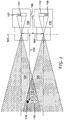
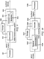
- FIG. 1 illustrates the concept of depth in a video image.
- FIG. 1 shows a right camera 105 with a sensor 107, and a left camera 110 with a sensor 112. Both cameras 105, 110 are capturing images of an object 115.
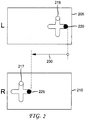
- object 115 is a physical cross, having an arbitrary detail 116 located on the right side of the cross (see FIG. 2 ).
- the right camera 105 has a capture angle 120
- the left camera 110 has a capture angle 125.
- the two capture angles 120, 125 overlap in a 3D stereo area 130.
- the cameras 105, 110 are also shown having a focal length 145.
- the focal length 145 is the distance from the exit pupil plane to the sensors 107, 112.
- the entrance pupil plane and the exit pupil plane are shown as coincident, when in most instances they are slightly separated.
- the cameras 105, 110 are shown as having a baseline length 150.
- the baseline length 150 is the distance between the centers of the entrance pupils of the cameras 105, 110, and therefore is measured at the stereo camera baseline 140.
- the object 115 is imaged by each of the cameras 105 and 110 as real images on each of the sensors 107 and 112. These real images include a real image 117 of the detail 116 on the sensor 107, and a real image 118 of the detail 116 on the sensor 112. As shown in FIG. 1 , the real images are flipped, as is known in the art.
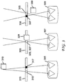
- the third observer 309 views a left view 335 of the object and a right view 337 of the object that have a negative disparity.
- the negative disparity reflects the fact that the left view 335 of the object is to the right of the right view 337 of the object on the screen 330.
- the negative disparity results in a perceived, or virtual, object 339 appearing to be in front of the plane of the screen 330.
- FIG. 4 includes the camera 105 and the camera 110 positioned in a converging configuration rather than the parallel configuration of FIG. 1 .
- An angle 410 shows the lines of sight of the cameras 105, 110 converging, and the angle 410 may be referred to as the convergence angle.
- the resolution of a dense disparity map is substantially the same as, but different from, the resolution of the associated image.
- the disparity information at the image boundaries are difficult to obtain. Therefore, in that implementation, the disparity values at the boundary pixels are not included in the disparity map, and the disparity map is smaller than the associated image.
- graphics are inserted into a background of an image.
- a 3D presentation includes a stereoscopic video interview between a sportscaster and a football player, both of whom are in the foreground.
- the background includes a view of a stadium.
- a disparity map is used to select pixels from the stereoscopic video interview when the corresponding disparity values are less than (that is, nearer than) a predetermined value.
- pixels are selected from a graphic if the disparity values are greater than (that is, farther than) the predetermined value. This allows, for example, a director to show the interview participants in front of a graphic image, rather than in front of the actual stadium background.
- the background is substituted with another environment, such as, for example, the playfield during a replay of the player's most recent scoring play.
- extrapolation rather than interpolation, is performed to exaggerate the apparent depth and thereby increase the 3D effect.
- a new view is extrapolated corresponding to a virtual camera having an increased baseline length relative to one of the original left and right views.
- a disparity value may be represented in a variety of formats. Several implementations use the following format to represent a disparity value for storage or transmission:
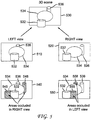
- FIG. 5 shows a left view 510 and a right view 520 that combine, in a viewer's brain, to produce a 3D scene 530.
- the left view 510, the right view 520, and the 3D scene 530 each contain three objects, which include a wide cylinder 532, an oval 534, and a thin cylinder 536.
- two of the three objects 532, 534, 536 are in different relative locations in each of the views 510, 520 and the 3D scene 530.
- Those two objects are the wide cylinder 532 and the thin cylinder 536.
- the oval 534 is in the same relative location in each of the views 510, 520 and the 3D scene 530.
- a pixel L is located in row N and has a horizontal coordinate x L in the left-eye image. Pixel L is determined to have a disparity value d L .
- a pixel R is located in row N of the corresponding right-eye image and has a horizontal coordinate nearest x L + d L . The pixel R is determined to have a disparity value d R of about "-d L ". Then, with a high degree of confidence, there is no occlusion at L or R because the disparities correspond to each other. That is, the pixels L and R both point to each other, generally, with their determined disparities.
- d R is not substantially the same as -d L , then there may be an occlusion.
- the two disparity values are substantially different, after accounting for the sign, then there is generally a high degree of confidence that there is an occlusion. Substantial difference is indicated, in one implementation, by
- one of the disparity values (either d R or d L ) is unavailable, then there is generally a high degree of confidence that there is an occlusion.
- a disparity value may be unavailable because, for example, the disparity value cannot be determined.
- the occlusion generally relates to one of the two images. For example, the portion of the scene shown by the pixel associated with the disparity having the smaller magnitude, or shown by the pixel corresponding to the unavailable disparity value, is generally considered to be occluded in the other image.
- disparity values are useful and can be effective.
- Some other implementations represent disparity values as a percentage value. Therefore, instead of representing the disparity as a number of pixels, the disparity is represented as a percentage of the horizontal resolution. For example, if the disparity for a given pixel location is ten pixels, and the horizontal resolution is 1920, then the percentage disparity value is (10/1920)*100. Such implementations can also provide sub-pixel accuracy in disparity.
- a percentage value representation is typically a floating point representation, rather than an integer representation. For example, one pixel of disparity in a display having a horizontal resolution of 1920 is 1/1920, which is 0.0005208 or .05208%.
- such percentage disparity values can be applied directly to other horizontal resolutions. For example, assume that (i) a video image has a horizontal resolution of 1920, (ii) the video image is transmitted to a user's home, and (iii) the user's display device has a horizontal resolution of 1440.
- the user's display device or set-top box, or some other processor or processing device typically converts the video image's horizontal resolution from 1920 to 1440, and also converts the disparity values so that the disparity values correspond to a horizontal resolution of 1440. The conversion may be performed, for example, by multiplying the percentage disparity value by the horizontal resolution.
- the absolute disparity value is 1 ⁇ 2 * 1920 / 100.
- Several of these implementations use a single disparity value, which is a percentage disparity value, in the transmission and storage of disparity values, regardless of the horizontal resolution of the video image and the disparity map. Such implementations are also useful, and can be effective.
- a transmission system may use a horizontal resolution in the transmission format that is different from the horizontal resolution of the video image.
- a receiving system may use a different horizontal resolution to display the video image.
- a conversion from one horizontal resolution to another horizontal resolution may be required.
- Such a conversion not only changes the resolution of the video image, but also requires that the disparity values be adjusted.
- Such a conversion would generally be required for absolute disparity values, but not for percentage disparity values.
- Another solution is to use an integer value that is not specific to any one common resolution. (Note that pictures are typically assumed to have been rectified vertically as well as receiving other processing. Accordingly, it is typically sufficient to discuss disparity in terms of horizontal displacement.)
- This solution proposes to define a reference resolution (or virtual resolution) of 11,520 pixels, which is referred to in this application as the smallest common multiple ("SCM") of several standard TV horizontal resolutions (720, 960, 1280, 1440, 1920). Note that the SCM is also referred to in various references as the "lowest common multiple" or "least common multiple".
- one or more SCM implementations (1) determine the disparity values for the existing horizontal resolution of the corresponding video content, (2) convert those disparity values to the scale of 11,520 with a simple multiplication and/or division to create an SCM disparity value, (3) store and transmit the SCM disparity values without transcoding, and (4) convert the received SCM disparity values to the resolution of the output display using a simple multiplication and/or division. Because there is no transcoding, this solution would generally not suffer from loss of information (for example, rounding losses) due to transcoding. Note that the resolution of the disparity map is not changed by the above process. Rather, the existing disparity values (for the existing resolution) are scaled so that they are based on, or reflect, a reference resolution (or virtual resolution) that is different from the actual resolution.
- FIG. 7 provides more detail into the process of determining a smallest common multiple for various different horizontal resolutions.
- a column 710 lists the different horizontal resolutions.
- the 11,520 resolution is used with resolutions of 2k, 4k, and 8k, by multiplying by an appropriate power of 2, and then dividing by the factors 3 2 and 5 which are not present in 2k, 4k, and 8k. Note that multiplying by a power of 2 is performed, in various implementations, using a bitwise left-shift operation, rather than an actual multiplication operation.
- FIG. 7 includes a column 730 that provides the conversion equation to convert between 11,520 and the various resolutions shown in the column 610.
- 11,520 is used for various implementations. However, other values are used in other implementations. In one implementation, the 11,520 value is doubled to 23,040. In a second implementation, the 368,640 value is doubled to 737,280.
- Yet another implementation conserves a bit by considering the sign of the disparity to be implicit. For example, the disparity of pixels in a left view is coded, along with the sign of the disparity. However, the disparity of corresponding pixels in a corresponding right view are assumed to have the opposite sign.
- Another implementation in order to be able to provide one dense disparity map per view (both left view and right view), and thereby to reduce issues caused by occlusions, allocates a bit to indicate the view to which the dense disparity map corresponds.
- Another implementation provides an implicit association between an image (either a left image or a right image) and a corresponding dense disparity map, and therefore does not need to devote a bit to this information.
- Variations on these implementations use one or more additional bits to introduce other types of maps or images.
- One such implementation uses two bits to indicate whether the map is (i) a left image disparity map, (ii) a right image disparity map, (iii) an occlusion map, or (iv) a transparency map.
- One implementation has a sixteen bit format, and uses 11 bits to indicate a range of - 900 to +480, two bits to indicate the type of map, and has three bits unused.
- FIG. 8 includes a processing chain 810 that processes video.
- a video image 811 has a horizontal resolution of 1920.
- the transmission format of the processing chain 810 has a horizontal resolution of 1280.
- the video image 811 is filtered and down-sampled in an operation 812 to produce a video image 813 having a horizontal resolution of 1280.
- the filtering and down-sampling are performed together in the processing chain 810.
- Other implementations perform the filtering and down-sampling separately, however.
- the filtering is used, for example, to low-pass filter the video image 811 with the goal of preventing aliasing when the video image 811 is down-sampled.
- the video image 813 is conveyed in a transmission and/or storage operation 814.
- a receiving side of the chain 810 accesses a received video image 815, which can be the same as, similar to, or different from, the video image 813.
- the video image 815 is a stored version of the video image 813.
- the video image 815 represents a reconstructed version of the video image 813 after source encoding and decoding operations (not shown).
- the video image 815 represents an error-corrected version of the video image 813 after channel encoding and decoding (including error correction) operations (not shown).
- the video image 815 is processed in an upsampling operation 816 to produce a video image 817 having the 1920 horizontal resolution, as in the original video image 811.
- FIG. 8 also includes a processing chain 820 that processes disparity images corresponding to the video images processed in the chain 810.
- a disparity image 821 has a horizontal resolution of 1920, and includes integer-valued disparity values based on a resolution of 11,520.
- a disparity image refers generally to any accumulation of disparity information, such as, for example, a dense disparity map, a down-sampled disparity map, or a sparse disparity map.
- the disparity map may correspond, for example, to a picture, a frame, a field, a slice, a macroblock, a partition, or some other collection of disparity information.
- the transmission format of the processing chain 820 has a horizontal resolution of 1280. Accordingly, the disparity image 821 is filtered and down-sampled in an operation 822 to produce a disparity image 823 having a horizontal resolution of 1280.
- the filtering and down-sampling are performed together in the processing chain 820. Other implementations perform the filtering and down-sampling separately, however.
- the filtering is used, for example, to low-pass filter the disparity values of the disparity image 821 with the goal of preventing aliasing when the disparity image 821 is down-sampled.
- the disparity values of the disparity image 823 are integer values. This may be accomplished in various ways. In one implementation, the result of the filtering and down-sampling operations is rounded to the nearest integer. In another implementation, any fractional portion is simply discarded. Yet another implementation uses a floating point representation for the disparity values of the disparity image 823. Note that the disparity values are still based on a resolution of 11,520 even after the filtering and down-sampling produces a resolution for the disparity image 823 of 1280.
- the disparity image 823 is conveyed in a transmission and/or storage operation 824.
- a receiving side of the chain 820 accesses a received disparity image 825.
- the disparity image 825 can be the same as, similar to, or different from, the disparity image 823.
- the disparity image 825 is a stored version of the disparity image 823.
- the disparity image 825 represents a reconstructed version of the disparity image 823 after source encoding and decoding operations (not shown).
- the disparity image 825 represents an error-corrected version of the disparity image 823 after channel encoding and decoding (including error correction) operations (not shown).
- the disparity values in the disparity image 825 remain as integers, however, by, for example, using rounding if needed.
- the conversion operation 828 divides each disparity value by six, as explained above.
- the conversion operation 828 produces a disparity image 829.
- the disparity values of the disparity image 829 are represented as floating point numbers in order to preserve sub-pixel accuracy.
- the processing chain 820 includes at least significant advantages.
- the disparity values are integers throughout the chain 820 until the final disparity image 829 is provided.
- the actual disparity values are not transcoded, despite the fact that the transmission format's horizontal resolution is different from the horizontal resolution of the native disparity map 821.
- the disparity values are applicable to a variety of different horizontal resolutions.
- a receiving system then processes the video image 817, using the disparity image 829.
- the processing may include, as explained earlier, adjusting 3D effects, positioning subtitles, inserting graphics, or performing visual effects.
- FIG. 8 also depicts a processing chain 830 for comparison purposes.
- the processing chain 830 also processes disparity images corresponding to the video images processed in the chain 810.
- the processing chain 830 is an alternative to the processing chain 820. It should be clear that the entire chain 830 is not shown in order to simplify FIG. 8 , as will be explained below.
- a disparity image 831 has a horizontal resolution of 1920, and includes percentage-based disparity values having a floating point representation.
- the transmission format of the processing chain 830 has a horizontal resolution of 1280.
- the disparity image 831 is filtered and down-sampled in an operation 832 to produce a disparity image 833 having a horizontal resolution of 1280.
- the operation 832 may be analogous, for example, to the filtering and down-sampling operation 812 or 822.
- the percentage-based disparity values of the disparity image 833 continue to be represented in a floating point format.
- a disparity image 841 has a horizontal resolution of 1920, and includes disparity values based on the 1920 resolution and having a floating point representation.
- the transmission format of the processing chain 840 has a horizontal resolution of 1280.
- the disparity image 841 is filtered and down-sampled in an operation 842 to produce a disparity image 843 having a horizontal resolution of 1280.
- the operation 842 may be analogous, for example, to the filtering and down-sampling operation 812, 822, or 823.
- the disparity values of the disparity image 843 continue to be represented in a floating point format.
- the conversion operation 850 is not performed.
- the disparity values of the disparity image 843 remain as disparity values that are based on a horizontal resolution of 1920.
- the horizontal resolution of the disparity image 843 remains as 1280.
- this implementation avoids the conversion prior to transmission, and possibly avoids a re-conversion after reception or retrieval. Avoiding conversion and re-conversion also avoids rounding errors in at least some implementations.
- This implementation as with all other implementations in this application, has advantages and can be useful.
- the disparity values are represented with floating point numbers throughout the implementation.
- the video transmission system or apparatus 900 may be, for example, a head-end or transmission system for transmitting a signal using any of a variety of media, such as, for example, satellite, cable, telephone-line, or terrestrial broadcast.
- the video transmission system or apparatus 900 also, or alternatively, may be used, for example, to provide a signal for storage.
- the transmission may be provided over the Internet or some other network.
- the video transmission system or apparatus 900 is capable of generating and delivering, for example, video content and other content such as, for example, indicators of depth including, for example, depth and/or disparity values. It should also be clear that the blocks of FIG. 9 provide a flow diagram of a video transmission process, in addition to providing a block diagram of a video transmission system or apparatus.
- the video transmission system or apparatus 900 receives input video from a processor 901.
- the processor 901 simply provides original-resolution images, such as the disparity images 821, 831, 841 and/or the video image 811, to the video transmission system or apparatus 900.
- the processor 901 is a processor configured for performing filtering and down-sampling, for example, as described above with respect to the operations 812, 822, 832, 842 to produce images such as the video image 813 and/or the disparity images 823, 833, 843.
- the encoder 902 may include sub-modules, including for example an assembly unit for receiving and assembling various pieces of information into a structured format for storage or transmission.
- the various pieces of information may include, for example, coded or uncoded video, coded or uncoded disparity (or depth) values, and coded or uncoded elements such as, for example, motion vectors, coding mode indicators, and syntax elements.
- the encoder 902 includes the processor 901 and therefore performs the operations of the processor 901.
- the transmitter 904 receives the encoded signal(s) from the encoder 902 and transmits the encoded signal(s) in one or more output signals.
- the transmitter 904 may be, for example, adapted to transmit a program signal having one or more bitstreams representing encoded pictures and/or information related thereto.
- Typical transmitters perform functions such as, for example, one or more of providing error-correction coding, interleaving the data in the signal, randomizing the energy in the signal, and modulating the signal onto one or more carriers using a modulator 906.
- the transmitter 904 may include, or interface with, an antenna (not shown). Further, implementations of the transmitter 904 may be limited to the modulator 906.
- a video receiving system or apparatus 1000 is shown to which the features and principles described above may be applied.
- the video receiving system or apparatus 1000 may be configured to receive signals over a variety of media, such as, for example, satellite, cable, telephone-line, or terrestrial broadcast.
- the signals may be received over the Internet or some other network.
- FIG. 10 provide a flow diagram of a video receiving process, in addition to providing a block diagram of a video receiving system or apparatus.
- the video receiving system or apparatus 1000 may be, for example, a cell-phone, a computer, a set-top box, a television, or other device that receives encoded video and provides, for example, decoded video signal for display (display to a user, for example), for processing, or for storage.
- the video receiving system or apparatus 1000 may provide its output to, for example, a screen of a television, a computer monitor, a computer (for storage, processing, or display), or some other storage, processing, or display device.
- the video receiving system or apparatus 1000 is capable of receiving and processing video information, and the video information may include, for example, video images, and/or disparity (or depth) images.
- the video receiving system or apparatus 1000 includes a receiver 1002 for receiving an encoded signal, such as, for example, the signals described in the implementations of this application.
- the receiver 1002 may receive, for example, a signal providing one or more of the video image 815 and/or the disparity image 825, or a signal output from the video transmission system 900 of FIG. 9 .
- the receiver 1002 may be, for example, adapted to receive a program signal having a plurality of bitstreams representing encoded pictures. Typical receivers perform functions such as, for example, one or more of receiving a modulated and encoded data signal, demodulating the data signal from one or more carriers using a demodulator 1004, de-randomizing the energy in the signal, de-interleaving the data in the signal, and error-correction decoding the signal.
- the receiver 1002 may include, or interface with, an antenna (not shown). Implementations of the receiver 1002 may be limited to the demodulator 1004.
- the video receiving system or apparatus 1000 includes a decoder 1006.
- the receiver 1002 provides a received signal to the decoder 1006.
- the signal provided to the decoder 1006 by the receiver 1002 may include one or more encoded bitstreams.
- the decoder 1006 outputs a decoded signal, such as, for example, decoded video signals including video information.
- the decoder 1006 may be, for example, an AVC decoder.
- the video receiving system or apparatus 1000 is also communicatively coupled to a storage unit 1007.
- the storage unit 1007 is coupled to the receiver 1002, and the receiver 1002 accesses a bitstream from the storage unit 1007.
- the storage unit 1007 is coupled to the decoder 1006, and the decoder 1006 accesses a bitstream from the storage unit 1007.
- the bitstream accessed from the storage unit 1007 includes, in different implementations, one or more encoded bitstreams.
- the storage unit 1007 is, in different implementations, one or more of a standard DVD, a Blu-Ray disc, a hard drive, or some other storage device.
- the output video from the decoder 1006 is provided, in one implementation, to a processor 1008.
- the processor 1008 is, in one implementation, a processor configured for performing upsampling such as that described, for example, with respect to upsampling operations 816 and/or 826.
- the decoder 1006 includes the processor 1008 and therefore performs the operations of the processor 1008.
- the processor 1008 is part of a downstream device such as, for example, a set-top box or a television.
- At least one implementation uses an extra bit to allow for 2 disparity maps to be generated.
- a first disparity map is computed with respect to a "left" view
- a second disparity map is computed with respect to a "right” view.
- having two disparity maps allows for improved handling of occlusions. For example, by comparing the corresponding disparity values, a system can determine whether an occlusion exists, and if so, then take steps to fill the resulting hole.
- Additional implementations provide more disparity maps, and allocate an appropriate number of bits to accommodate the number of disparity maps.
- MVC which refers to AVC with the MVC extension (Annex G)
- Annex G MVC extension
- an implementation may only transmit disparity maps with respect to a subset of views.
- Disparity may be calculated, for example, in a manner similar to calculating motion vectors.
- disparity may be calculated from depth values, as is known and described above.
- Various implementations also have advantages resulting from the use of disparity values instead of depth values. Such advantages may include: (1) disparity values are bounded, whereas depth values may go to infinity and so depth values are harder to represent/encode, (2) disparity values can be represented directly, whereas a logarithmic scaling is often needed to represent the potentially very large depth values. Additionally, it is generally simple to determine depth from the disparity. Metadata is included in various implementations to provide information such as focal length, baseline distance (length), and convergence plane distance. Convergence plane distance is the distance at which the camera axes intersect when the cameras are converging. The point at which camera axes intersect can be seen in FIG. 4 as the vertex of the angle 410. When the cameras are parallel, the convergence plane distance is at infinite distance.
- Dense disparity maps may allow a variety of applications, such as, for example, a relatively complex 3D effect adjustment on a consumer device, and a relatively simple sub-title placement in post-production.
- applications such as, for example, a relatively complex 3D effect adjustment on a consumer device, and a relatively simple sub-title placement in post-production.
- variations of these implementations and additional applications are contemplated and within our disclosure, and features and aspects of described implementations may be adapted for other implementations.
- Determining the information may include one or more of, for example, estimating the information, calculating the information, predicting the information, or retrieving the information from memory.
- a given display may support multiple different resolutions. Therefore, the given display may be able to display video content having a resolution of, for example, either 1280, 1440, or 1920. Nonetheless, the given display is often referred to as a 1920 display because the highest supported resolution is 1920.
- the individual elements of the image may comprise multiple pixels. For example, if a display can support a horizontal resolution of 800 and 1920, then the display is typically at least 1920 pixels wide. When the display is displaying an 800 resolution image it is possible that the display allocates at least a portion of three or more pixels to each element of the image.
- an encoder for example, the encoder 902
- a decoder for example, the decoder 1006
- a post-processor for example, the processor 1008
- a pre-processor for example, the processor 901
- Processors also include communication devices, such as, for example, computers, cell phones, portable/personal digital assistants (“PDAs”), and other devices that facilitate communication of information between end-users.
- communication devices such as, for example, computers, cell phones, portable/personal digital assistants ("PDAs"), and other devices that facilitate communication of information between end-users.
- PDAs portable/personal digital assistants
Landscapes
- Engineering & Computer Science (AREA)
- Multimedia (AREA)
- Signal Processing (AREA)
- Testing, Inspecting, Measuring Of Stereoscopic Televisions And Televisions (AREA)
- Processing Or Creating Images (AREA)
- Image Generation (AREA)
- Television Systems (AREA)
Claims (9)
- Procédé comprenant les étapes suivantes :accès à une valeur de disparité pour un emplacement spécifique d'une image, l'image étant destinée à être affichée sur un dispositif d'affichage standardayant une résolution spécifique et la valeur de disparité correspondant à une autre résolution qui est supérieure à la résolution maximale de tout dispositif d'affichage standard et qui est un entier correspondant à un plus petit multiple commun de résolutions multiples prises en charge par le dispositif d'affichage standard ;modification de la valeur de disparité accédée en réduisant l'échelle de la valeur de disparité accédée pour produire une valeur de disparité modifiée correspondant à la résolution spécifique.
- Procédé selon la revendication 1, dans lequel la résolution spécifique est une résolution horizontale et la valeur de disparité est une disparité horizontale.
- Procédé selon l'une quelconque des revendications 1 à 2, dans lequel la modification comprend la mise à l'échelle de la valeur de disparité accédée d'après un multiple commun des résolutions multiples.
- Procédé selon la revendication 3, dans lequel le multiple commun est le plus petit multiple commun des résolutions multiples.
- Procédé selon la revendication 3 ou 4, dans lequel le multiple commun est 11 520.
- Procédé selon la revendication 5, dans lequel l'entier fournit une précision de sous-pixel de la disparité pour les résolutions multiples.
- Appareil comprenant :un moyen pour accéder à une valeur de disparité pour un emplacement spécifique d'une image, l'image étant destinée à être affichée sur un dispositif d'affichage standardayant une résolution spécifique et la valeur de disparité correspondant à une autre résolution qui est supérieure à la résolution maximale de tout dispositif d'affichage standard et qui est un entier correspondant à un plus petit multiple commun de résolutions multiples prises en charge par le dispositif d'affichage standard ; et un moyen adapté pour modifier la valeur de disparité accédée en réduisant l'échelle de la valeur de disparité accédée pour produire une valeur de disparité modifiée correspondant à la résolution spécifique.
- Support lisible par un processeur sur lequel sont stockées des instructions permettant à un ou plusieurs processeurs d'exécuter collectivement le procédé selon les revendications 1 à 6.
- Appareil selon la revendication 7, comprenant :un démodulateur pour démoduler un signal qui inclut des données indiquant une valeur de disparité pour un emplacement spécifique d'une image, l'image ayant une résolution spécifique et la valeur de disparité correspondant à une autre résolution de l'image qui est différente de et supérieure à la résolution spécifique et qui est basée sur des résolutions inférieures possibles multiples pour l'image ; etun processeur configuré pour modifier la valeur de disparité accédée en réduisant l'échelle de la valeur de disparité accédée pour produire une valeur de disparité modifiée correspondant à la résolution spécifique.
Applications Claiming Priority (3)
| Application Number | Priority Date | Filing Date | Title |
|---|---|---|---|
| US31956610P | 2010-03-31 | 2010-03-31 | |
| US39741810P | 2010-06-11 | 2010-06-11 | |
| PCT/IB2011/000708 WO2011121437A1 (fr) | 2010-03-31 | 2011-03-31 | Cartes de disparité en 3d |
Publications (2)
| Publication Number | Publication Date |
|---|---|
| EP2553933A1 EP2553933A1 (fr) | 2013-02-06 |
| EP2553933B1 true EP2553933B1 (fr) | 2018-10-24 |
Family
ID=44246501
Family Applications (1)
| Application Number | Title | Priority Date | Filing Date |
|---|---|---|---|
| EP11726942.3A Active EP2553933B1 (fr) | 2010-03-31 | 2011-03-31 | Cartes de disparité en 3d |
Country Status (11)
| Country | Link |
|---|---|
| US (1) | US10791314B2 (fr) |
| EP (1) | EP2553933B1 (fr) |
| JP (1) | JP6073214B2 (fr) |
| KR (1) | KR101825761B1 (fr) |
| CN (2) | CN106131531B (fr) |
| AU (1) | AU2011234163B2 (fr) |
| BR (1) | BR112012024955B1 (fr) |
| CA (1) | CA2795021C (fr) |
| HK (1) | HK1182245A1 (fr) |
| MX (1) | MX340111B (fr) |
| WO (1) | WO2011121437A1 (fr) |
Families Citing this family (24)
| Publication number | Priority date | Publication date | Assignee | Title |
|---|---|---|---|---|
| KR101825761B1 (ko) * | 2010-03-31 | 2018-03-22 | 톰슨 라이센싱 | 3d 디스패리티 맵들 |
| EP2608553A4 (fr) * | 2010-08-19 | 2014-04-16 | Panasonic Corp | Dispositif de capture d'image stéréoscopique et procédé de capture d'image stéréoscopique |
| TWI475515B (zh) * | 2011-04-13 | 2015-03-01 | Univ Nat Taiwan | 產生立體影片之深度圖的方法 |
| AU2011368712A1 (en) * | 2011-05-26 | 2013-12-05 | Thomson Licensing | Scale-independent maps |
| KR20140120000A (ko) * | 2013-04-01 | 2014-10-13 | 한국전자통신연구원 | 3차원공간의 분석을 통한 입체영상 자막 생성 장치 및 방법 |
| US9460855B2 (en) * | 2013-10-01 | 2016-10-04 | Samsung Electro-Mechanics Co., Ltd. | Multilayer ceramic capacitor and board having the same |
| US10244223B2 (en) | 2014-01-10 | 2019-03-26 | Ostendo Technologies, Inc. | Methods for full parallax compressed light field 3D imaging systems |
| KR101882931B1 (ko) | 2014-07-10 | 2018-07-30 | 삼성전자주식회사 | 다시점 영상 디스플레이 장치 및 그의 디스패리티 측정 방법 |
| CN105323573B (zh) * | 2014-07-16 | 2019-02-05 | 北京三星通信技术研究有限公司 | 三维图像显示装置和方法 |
| TWI556624B (zh) * | 2014-07-18 | 2016-11-01 | 友達光電股份有限公司 | 影像顯示方法以及影像顯示裝置 |
| CN105491277B (zh) * | 2014-09-15 | 2018-08-31 | 联想(北京)有限公司 | 图像处理方法和电子设备 |
| CN106471803A (zh) * | 2014-12-04 | 2017-03-01 | 深圳市大疆创新科技有限公司 | 成像系统及方法 |
| JP7036599B2 (ja) | 2015-04-23 | 2022-03-15 | オステンド・テクノロジーズ・インコーポレーテッド | 奥行き情報を用いて全方向視差を圧縮したライトフィールドを合成する方法 |
| EP3286916A1 (fr) | 2015-04-23 | 2018-02-28 | Ostendo Technologies, Inc. | Procédés et appareil pour systèmes d'affichage à champ lumineux à parallaxe totale |
| US10448030B2 (en) | 2015-11-16 | 2019-10-15 | Ostendo Technologies, Inc. | Content adaptive light field compression |
| US10453431B2 (en) | 2016-04-28 | 2019-10-22 | Ostendo Technologies, Inc. | Integrated near-far light field display systems |
| US11051039B2 (en) | 2017-06-02 | 2021-06-29 | Ostendo Technologies, Inc. | Methods for full parallax light field compression |
| US20180350038A1 (en) | 2017-06-02 | 2018-12-06 | Ostendo Technologies, Inc. | Methods and Systems for Light Field Compression With Residuals |
| US10432944B2 (en) | 2017-08-23 | 2019-10-01 | Avalon Holographics Inc. | Layered scene decomposition CODEC system and methods |
| CN107436500B (zh) * | 2017-08-25 | 2020-04-24 | 京东方科技集团股份有限公司 | 光栅及制备方法、驱动方法、裸眼三维显示系统 |
| US10931956B2 (en) * | 2018-04-12 | 2021-02-23 | Ostendo Technologies, Inc. | Methods for MR-DIBR disparity map merging and disparity threshold determination |
| US11172222B2 (en) | 2018-06-26 | 2021-11-09 | Ostendo Technologies, Inc. | Random access in encoded full parallax light field images |
| US11182630B2 (en) | 2019-03-29 | 2021-11-23 | Advanced New Technologies Co., Ltd. | Using an illumination sequence pattern for biometric authentication |
| US20200314411A1 (en) * | 2019-03-29 | 2020-10-01 | Alibaba Group Holding Limited | Synchronizing an illumination sequence of illumination sources with image capture in rolling shutter mode |
Citations (5)
| Publication number | Priority date | Publication date | Assignee | Title |
|---|---|---|---|---|
| US5926567A (en) * | 1995-03-01 | 1999-07-20 | Compaq Computer Corporation | Method and apparatus for storing and rapidly displaying graphic data |
| US20060290778A1 (en) * | 2003-08-26 | 2006-12-28 | Sharp Kabushiki Kaisha | 3-Dimensional video reproduction device and 3-dimensional video reproduction method |
| EP1807806A1 (fr) * | 2004-10-26 | 2007-07-18 | Koninklijke Philips Electronics N.V. | Carte de disparite |
| US20080136819A1 (en) * | 2006-12-11 | 2008-06-12 | Michael Shivas | Apparatus and method for screen scaling displays on communication devices |
| US8090195B2 (en) * | 2008-02-12 | 2012-01-03 | Panasonic Corporation | Compound eye imaging apparatus, distance measuring apparatus, disparity calculation method, and distance measuring method |
Family Cites Families (51)
| Publication number | Priority date | Publication date | Assignee | Title |
|---|---|---|---|---|
| US5025325A (en) | 1989-10-13 | 1991-06-18 | Hewlett-Packard Company | Graphics scaling method for high resolution printers |
| JPH0818954A (ja) * | 1994-06-24 | 1996-01-19 | Sharp Corp | 画像伝送装置 |
| CN1132123A (zh) | 1995-03-25 | 1996-10-02 | 国营无锡市新峰石化管件厂 | 短半径弯头加工工艺 |
| US6384859B1 (en) | 1995-03-29 | 2002-05-07 | Sanyo Electric Co., Ltd. | Methods for creating an image for a three-dimensional display, for calculating depth information and for image processing using the depth information |
| JPH11127339A (ja) * | 1997-10-23 | 1999-05-11 | Fuji Xerox Co Ltd | 画像処理装置 |
| US7092003B1 (en) | 1999-01-21 | 2006-08-15 | Mel Siegel | 3-D imaging arrangements |
| TW421969B (en) | 1999-03-19 | 2001-02-11 | Asustek Comp Inc | 3D image processing device and method |
| JP2000321050A (ja) | 1999-05-14 | 2000-11-24 | Minolta Co Ltd | 3次元データ取得装置および3次元データ取得方法 |
| US20020145610A1 (en) | 1999-07-16 | 2002-10-10 | Steve Barilovits | Video processing engine overlay filter scaler |
| TW452757B (en) | 1999-08-17 | 2001-09-01 | Trumpion Microelectronics Inc | Image processing device in accordance with the resolution adjustment of flat panel display |
| JP2001306287A (ja) * | 2000-04-25 | 2001-11-02 | Ricoh Co Ltd | 異機種間代行印刷システム |
| JP3736379B2 (ja) | 2001-04-19 | 2006-01-18 | ソニー株式会社 | 電子透かし埋め込み処理装置、電子透かし検出処理装置、および電子透かし埋め込み処理方法、電子透かし検出処理方法、並びにプログラム記憶媒体、およびプログラム |
| US6873717B2 (en) * | 2002-07-09 | 2005-03-29 | Riverain Medical Group, Llc | Input/output interface for computer aided diagnosis (CAD) system |
| KR100439341B1 (ko) | 2002-08-27 | 2004-07-07 | 한국전자통신연구원 | 시각 피로 감소를 위한 스테레오 영상의 초점심도 조정장치 및 그 방법 |
| CN101841728B (zh) | 2003-04-17 | 2012-08-08 | 夏普株式会社 | 三维图像处理装置 |
| JP4251907B2 (ja) | 2003-04-17 | 2009-04-08 | シャープ株式会社 | 画像データ作成装置 |
| US20050132191A1 (en) | 2003-12-16 | 2005-06-16 | Joshi Ajit P. | Method for authenticating different rendering devices with different service providers |
| KR100636221B1 (ko) | 2005-01-29 | 2006-10-19 | 삼성전자주식회사 | 컨텐츠를 선택하여 재생/기록하는 방법 및 그 장치 |
| KR100727940B1 (ko) | 2005-06-22 | 2007-06-14 | 삼성전자주식회사 | 통신 채널을 이용한 3d 입체 영상의 화질 조정 방법 |
| KR100667810B1 (ko) | 2005-08-31 | 2007-01-11 | 삼성전자주식회사 | 3d 영상의 깊이감 조정 장치 및 방법 |
| EP1952199B1 (fr) | 2005-11-17 | 2012-10-03 | Nokia Corporation | Procede et dispositifs de generation, transfert et traitement de donnees d'images tridimensionnelles |
| US7738712B2 (en) | 2006-01-04 | 2010-06-15 | Aten International Co., Ltd. | Mixing 2-D gradient-difference and interpolation/decimation method and device for scaling a digital image |
| US8044994B2 (en) | 2006-04-04 | 2011-10-25 | Mitsubishi Electric Research Laboratories, Inc. | Method and system for decoding and displaying 3D light fields |
| US7609906B2 (en) | 2006-04-04 | 2009-10-27 | Mitsubishi Electric Research Laboratories, Inc. | Method and system for acquiring and displaying 3D light fields |
| US7916934B2 (en) | 2006-04-04 | 2011-03-29 | Mitsubishi Electric Research Laboratories, Inc. | Method and system for acquiring, encoding, decoding and displaying 3D light fields |
| ATE523861T1 (de) | 2006-10-04 | 2011-09-15 | Koninkl Philips Electronics Nv | Bildverbesserung |
| KR101311896B1 (ko) | 2006-11-14 | 2013-10-14 | 삼성전자주식회사 | 입체 영상의 변위 조정방법 및 이를 적용한 입체 영상장치 |
| JP4936869B2 (ja) * | 2006-12-12 | 2012-05-23 | 株式会社東芝 | 画像処理装置及び画像処理方法 |
| JP4909063B2 (ja) | 2006-12-28 | 2012-04-04 | キヤノン株式会社 | 撮像装置及び画像記録方法 |
| KR20080076628A (ko) | 2007-02-16 | 2008-08-20 | 삼성전자주식회사 | 영상의 입체감 향상을 위한 입체영상 표시장치 및 그 방법 |
| KR100778085B1 (ko) | 2007-03-14 | 2007-11-22 | 주식회사 이시티 | 주시각 제어를 위한 입체 영상 신호의 처리 방법 및 장치 |
| KR101345303B1 (ko) * | 2007-03-29 | 2013-12-27 | 삼성전자주식회사 | 스테레오 또는 다시점 영상의 입체감 조정 방법 및 장치 |
| JP5299734B2 (ja) * | 2007-07-30 | 2013-09-25 | Nltテクノロジー株式会社 | 画像処理方法、画像表示装置及びそのタイミングコントローラ |
| US8390674B2 (en) | 2007-10-10 | 2013-03-05 | Samsung Electronics Co., Ltd. | Method and apparatus for reducing fatigue resulting from viewing three-dimensional image display, and method and apparatus for generating data stream of low visual fatigue three-dimensional image |
| WO2009083863A1 (fr) | 2007-12-20 | 2009-07-09 | Koninklijke Philips Electronics N.V. | Reproduction et superposition de graphiques 3d sur une vidéo 3d |
| KR101510099B1 (ko) | 2008-01-11 | 2015-04-08 | 삼성전자주식회사 | 디지털 영상 처리 장치에서 다중 심도를 가진 3차원 메뉴디스플레이 방법 |
| JP2009238117A (ja) | 2008-03-28 | 2009-10-15 | Toshiba Corp | 多視差画像生成装置および方法 |
| JP4870120B2 (ja) | 2008-05-16 | 2012-02-08 | 株式会社Jvcケンウッド | 動画像階層符号化装置、動画像階層符号化方法、動画像階層符号化プログラム、動画像階層復号化装置、動画像階層復号化方法、および動画像階層復号化プログラム |
| BRPI0822737A2 (pt) | 2008-09-25 | 2015-06-23 | Tele Atlas Bv | Método e disposição para obscurecer uma imagem |
| JP2010098479A (ja) * | 2008-10-15 | 2010-04-30 | Sony Corp | 表示装置、表示方法及び表示システム |
| JP5235604B2 (ja) | 2008-10-20 | 2013-07-10 | キヤノン株式会社 | 画像処理装置および画像処理方法 |
| RU2546546C2 (ru) | 2008-12-01 | 2015-04-10 | Аймакс Корпорейшн | Способы и системы для представления трехмерных изображений движения с адаптивной к содержимому информацией |
| US8599242B2 (en) | 2008-12-02 | 2013-12-03 | Lg Electronics Inc. | Method for displaying 3D caption and 3D display apparatus for implementing the same |
| TW201101839A (en) | 2009-06-26 | 2011-01-01 | Liao Li Shi | System for encoding video and method, system for decoding video and method, system for displaying video and method |
| KR101678968B1 (ko) | 2009-08-21 | 2016-11-25 | 에스케이텔레콤 주식회사 | 참조 픽처 보간 방법 및 장치와 그를 이용한 영상 부호화/복호화 방법 및 장치 |
| US8374463B1 (en) * | 2010-01-06 | 2013-02-12 | Marseille Networks, Inc. | Method for partitioning a digital image using two or more defined regions |
| KR101825761B1 (ko) | 2010-03-31 | 2018-03-22 | 톰슨 라이센싱 | 3d 디스패리티 맵들 |
| GB2479784B (en) | 2010-04-23 | 2012-11-07 | Nds Ltd | Image scaling |
| US9035939B2 (en) | 2010-10-04 | 2015-05-19 | Qualcomm Incorporated | 3D video control system to adjust 3D video rendering based on user preferences |
| AU2011368712A1 (en) | 2011-05-26 | 2013-12-05 | Thomson Licensing | Scale-independent maps |
| CN103999461A (zh) | 2011-12-15 | 2014-08-20 | 汤姆逊许可公司 | 视频质量测量方法及装置 |
-
2011
- 2011-03-31 KR KR1020127028237A patent/KR101825761B1/ko active IP Right Grant
- 2011-03-31 MX MX2012011134A patent/MX340111B/es active IP Right Grant
- 2011-03-31 AU AU2011234163A patent/AU2011234163B2/en active Active
- 2011-03-31 BR BR112012024955-0A patent/BR112012024955B1/pt active IP Right Grant
- 2011-03-31 CN CN201610806820.9A patent/CN106131531B/zh active Active
- 2011-03-31 US US13/637,961 patent/US10791314B2/en active Active
- 2011-03-31 CN CN201180027121.XA patent/CN102934451B/zh active Active
- 2011-03-31 EP EP11726942.3A patent/EP2553933B1/fr active Active
- 2011-03-31 CA CA2795021A patent/CA2795021C/fr active Active
- 2011-03-31 JP JP2013501979A patent/JP6073214B2/ja active Active
- 2011-03-31 WO PCT/IB2011/000708 patent/WO2011121437A1/fr active Application Filing
-
2013
- 2013-08-09 HK HK13109319.0A patent/HK1182245A1/zh unknown
Patent Citations (5)
| Publication number | Priority date | Publication date | Assignee | Title |
|---|---|---|---|---|
| US5926567A (en) * | 1995-03-01 | 1999-07-20 | Compaq Computer Corporation | Method and apparatus for storing and rapidly displaying graphic data |
| US20060290778A1 (en) * | 2003-08-26 | 2006-12-28 | Sharp Kabushiki Kaisha | 3-Dimensional video reproduction device and 3-dimensional video reproduction method |
| EP1807806A1 (fr) * | 2004-10-26 | 2007-07-18 | Koninklijke Philips Electronics N.V. | Carte de disparite |
| US20080136819A1 (en) * | 2006-12-11 | 2008-06-12 | Michael Shivas | Apparatus and method for screen scaling displays on communication devices |
| US8090195B2 (en) * | 2008-02-12 | 2012-01-03 | Panasonic Corporation | Compound eye imaging apparatus, distance measuring apparatus, disparity calculation method, and distance measuring method |
Also Published As
| Publication number | Publication date |
|---|---|
| CN106131531A (zh) | 2016-11-16 |
| MX2012011134A (es) | 2012-11-12 |
| AU2011234163B2 (en) | 2015-10-29 |
| CN106131531B (zh) | 2019-04-26 |
| JP2013524608A (ja) | 2013-06-17 |
| BR112012024955A2 (pt) | 2016-07-12 |
| AU2011234163A1 (en) | 2012-10-11 |
| WO2011121437A1 (fr) | 2011-10-06 |
| CN102934451A (zh) | 2013-02-13 |
| US10791314B2 (en) | 2020-09-29 |
| JP6073214B2 (ja) | 2017-02-01 |
| CN102934451B (zh) | 2016-10-05 |
| CA2795021A1 (fr) | 2011-10-06 |
| EP2553933A1 (fr) | 2013-02-06 |
| US20130010057A1 (en) | 2013-01-10 |
| CA2795021C (fr) | 2020-06-16 |
| MX340111B (es) | 2016-06-27 |
| KR20130088012A (ko) | 2013-08-07 |
| BR112012024955B1 (pt) | 2021-12-07 |
| HK1182245A1 (zh) | 2013-11-22 |
| KR101825761B1 (ko) | 2018-03-22 |
Similar Documents
| Publication | Publication Date | Title |
|---|---|---|
| EP2553933B1 (fr) | Cartes de disparité en 3d | |
| EP2715661B1 (fr) | Cartes indépendantes de l'échelle | |
| EP2553932B1 (fr) | Indications de valeur de disparité | |
| US10055814B2 (en) | Image processing device and image processing method | |
| EP2201784B1 (fr) | Procédé et dispositif pour traiter une carte de profondeur | |
| US9986258B2 (en) | Efficient encoding of multiple views | |
| WO2011094164A1 (fr) | Systèmes d'optimisation d'image utilisant des informations de zone |
Legal Events
| Date | Code | Title | Description |
|---|---|---|---|
| PUAI | Public reference made under article 153(3) epc to a published international application that has entered the european phase |
Free format text: ORIGINAL CODE: 0009012 |
|
| 17P | Request for examination filed |
Effective date: 20121004 |
|
| AK | Designated contracting states |
Kind code of ref document: A1 Designated state(s): AL AT BE BG CH CY CZ DE DK EE ES FI FR GB GR HR HU IE IS IT LI LT LU LV MC MK MT NL NO PL PT RO RS SE SI SK SM TR |
|
| DAX | Request for extension of the european patent (deleted) | ||
| 17Q | First examination report despatched |
Effective date: 20140428 |
|
| GRAP | Despatch of communication of intention to grant a patent |
Free format text: ORIGINAL CODE: EPIDOSNIGR1 |
|
| STAA | Information on the status of an ep patent application or granted ep patent |
Free format text: STATUS: GRANT OF PATENT IS INTENDED |
|
| INTG | Intention to grant announced |
Effective date: 20180409 |
|
| GRAS | Grant fee paid |
Free format text: ORIGINAL CODE: EPIDOSNIGR3 |
|
| GRAA | (expected) grant |
Free format text: ORIGINAL CODE: 0009210 |
|
| STAA | Information on the status of an ep patent application or granted ep patent |
Free format text: STATUS: THE PATENT HAS BEEN GRANTED |
|
| AK | Designated contracting states |
Kind code of ref document: B1 Designated state(s): AL AT BE BG CH CY CZ DE DK EE ES FI FR GB GR HR HU IE IS IT LI LT LU LV MC MK MT NL NO PL PT RO RS SE SI SK SM TR |
|
| REG | Reference to a national code |
Ref country code: GB Ref legal event code: FG4D |
|
| REG | Reference to a national code |
Ref country code: CH Ref legal event code: EP |
|
| REG | Reference to a national code |
Ref country code: IE Ref legal event code: FG4D |
|
| REG | Reference to a national code |
Ref country code: AT Ref legal event code: REF Ref document number: 1058067 Country of ref document: AT Kind code of ref document: T Effective date: 20181115 |
|
| REG | Reference to a national code |
Ref country code: DE Ref legal event code: R096 Ref document number: 602011053186 Country of ref document: DE |
|
| REG | Reference to a national code |
Ref country code: NL Ref legal event code: FP |
|
| REG | Reference to a national code |
Ref country code: LT Ref legal event code: MG4D |
|
| REG | Reference to a national code |
Ref country code: AT Ref legal event code: MK05 Ref document number: 1058067 Country of ref document: AT Kind code of ref document: T Effective date: 20181024 |
|
| PG25 | Lapsed in a contracting state [announced via postgrant information from national office to epo] |
Ref country code: AT Free format text: LAPSE BECAUSE OF FAILURE TO SUBMIT A TRANSLATION OF THE DESCRIPTION OR TO PAY THE FEE WITHIN THE PRESCRIBED TIME-LIMIT Effective date: 20181024 Ref country code: NO Free format text: LAPSE BECAUSE OF FAILURE TO SUBMIT A TRANSLATION OF THE DESCRIPTION OR TO PAY THE FEE WITHIN THE PRESCRIBED TIME-LIMIT Effective date: 20190124 Ref country code: LV Free format text: LAPSE BECAUSE OF FAILURE TO SUBMIT A TRANSLATION OF THE DESCRIPTION OR TO PAY THE FEE WITHIN THE PRESCRIBED TIME-LIMIT Effective date: 20181024 Ref country code: FI Free format text: LAPSE BECAUSE OF FAILURE TO SUBMIT A TRANSLATION OF THE DESCRIPTION OR TO PAY THE FEE WITHIN THE PRESCRIBED TIME-LIMIT Effective date: 20181024 Ref country code: IS Free format text: LAPSE BECAUSE OF FAILURE TO SUBMIT A TRANSLATION OF THE DESCRIPTION OR TO PAY THE FEE WITHIN THE PRESCRIBED TIME-LIMIT Effective date: 20190224 Ref country code: LT Free format text: LAPSE BECAUSE OF FAILURE TO SUBMIT A TRANSLATION OF THE DESCRIPTION OR TO PAY THE FEE WITHIN THE PRESCRIBED TIME-LIMIT Effective date: 20181024 Ref country code: HR Free format text: LAPSE BECAUSE OF FAILURE TO SUBMIT A TRANSLATION OF THE DESCRIPTION OR TO PAY THE FEE WITHIN THE PRESCRIBED TIME-LIMIT Effective date: 20181024 Ref country code: ES Free format text: LAPSE BECAUSE OF FAILURE TO SUBMIT A TRANSLATION OF THE DESCRIPTION OR TO PAY THE FEE WITHIN THE PRESCRIBED TIME-LIMIT Effective date: 20181024 Ref country code: PL Free format text: LAPSE BECAUSE OF FAILURE TO SUBMIT A TRANSLATION OF THE DESCRIPTION OR TO PAY THE FEE WITHIN THE PRESCRIBED TIME-LIMIT Effective date: 20181024 Ref country code: BG Free format text: LAPSE BECAUSE OF FAILURE TO SUBMIT A TRANSLATION OF THE DESCRIPTION OR TO PAY THE FEE WITHIN THE PRESCRIBED TIME-LIMIT Effective date: 20190124 |
|
| PG25 | Lapsed in a contracting state [announced via postgrant information from national office to epo] |
Ref country code: GR Free format text: LAPSE BECAUSE OF FAILURE TO SUBMIT A TRANSLATION OF THE DESCRIPTION OR TO PAY THE FEE WITHIN THE PRESCRIBED TIME-LIMIT Effective date: 20190125 Ref country code: PT Free format text: LAPSE BECAUSE OF FAILURE TO SUBMIT A TRANSLATION OF THE DESCRIPTION OR TO PAY THE FEE WITHIN THE PRESCRIBED TIME-LIMIT Effective date: 20190224 Ref country code: AL Free format text: LAPSE BECAUSE OF FAILURE TO SUBMIT A TRANSLATION OF THE DESCRIPTION OR TO PAY THE FEE WITHIN THE PRESCRIBED TIME-LIMIT Effective date: 20181024 Ref country code: SE Free format text: LAPSE BECAUSE OF FAILURE TO SUBMIT A TRANSLATION OF THE DESCRIPTION OR TO PAY THE FEE WITHIN THE PRESCRIBED TIME-LIMIT Effective date: 20181024 Ref country code: RS Free format text: LAPSE BECAUSE OF FAILURE TO SUBMIT A TRANSLATION OF THE DESCRIPTION OR TO PAY THE FEE WITHIN THE PRESCRIBED TIME-LIMIT Effective date: 20181024 |
|
| REG | Reference to a national code |
Ref country code: DE Ref legal event code: R097 Ref document number: 602011053186 Country of ref document: DE |
|
| PG25 | Lapsed in a contracting state [announced via postgrant information from national office to epo] |
Ref country code: IT Free format text: LAPSE BECAUSE OF FAILURE TO SUBMIT A TRANSLATION OF THE DESCRIPTION OR TO PAY THE FEE WITHIN THE PRESCRIBED TIME-LIMIT Effective date: 20181024 Ref country code: CZ Free format text: LAPSE BECAUSE OF FAILURE TO SUBMIT A TRANSLATION OF THE DESCRIPTION OR TO PAY THE FEE WITHIN THE PRESCRIBED TIME-LIMIT Effective date: 20181024 Ref country code: DK Free format text: LAPSE BECAUSE OF FAILURE TO SUBMIT A TRANSLATION OF THE DESCRIPTION OR TO PAY THE FEE WITHIN THE PRESCRIBED TIME-LIMIT Effective date: 20181024 |
|
| PG25 | Lapsed in a contracting state [announced via postgrant information from national office to epo] |
Ref country code: SK Free format text: LAPSE BECAUSE OF FAILURE TO SUBMIT A TRANSLATION OF THE DESCRIPTION OR TO PAY THE FEE WITHIN THE PRESCRIBED TIME-LIMIT Effective date: 20181024 Ref country code: RO Free format text: LAPSE BECAUSE OF FAILURE TO SUBMIT A TRANSLATION OF THE DESCRIPTION OR TO PAY THE FEE WITHIN THE PRESCRIBED TIME-LIMIT Effective date: 20181024 Ref country code: SM Free format text: LAPSE BECAUSE OF FAILURE TO SUBMIT A TRANSLATION OF THE DESCRIPTION OR TO PAY THE FEE WITHIN THE PRESCRIBED TIME-LIMIT Effective date: 20181024 Ref country code: EE Free format text: LAPSE BECAUSE OF FAILURE TO SUBMIT A TRANSLATION OF THE DESCRIPTION OR TO PAY THE FEE WITHIN THE PRESCRIBED TIME-LIMIT Effective date: 20181024 |
|
| PLBE | No opposition filed within time limit |
Free format text: ORIGINAL CODE: 0009261 |
|
| STAA | Information on the status of an ep patent application or granted ep patent |
Free format text: STATUS: NO OPPOSITION FILED WITHIN TIME LIMIT |
|
| 26N | No opposition filed |
Effective date: 20190725 |
|
| REG | Reference to a national code |
Ref country code: GB Ref legal event code: 732E Free format text: REGISTERED BETWEEN 20190926 AND 20191002 |
|
| PG25 | Lapsed in a contracting state [announced via postgrant information from national office to epo] |
Ref country code: SI Free format text: LAPSE BECAUSE OF FAILURE TO SUBMIT A TRANSLATION OF THE DESCRIPTION OR TO PAY THE FEE WITHIN THE PRESCRIBED TIME-LIMIT Effective date: 20181024 Ref country code: MC Free format text: LAPSE BECAUSE OF FAILURE TO SUBMIT A TRANSLATION OF THE DESCRIPTION OR TO PAY THE FEE WITHIN THE PRESCRIBED TIME-LIMIT Effective date: 20181024 |
|
| REG | Reference to a national code |
Ref country code: CH Ref legal event code: PL |
|
| PG25 | Lapsed in a contracting state [announced via postgrant information from national office to epo] |
Ref country code: LU Free format text: LAPSE BECAUSE OF NON-PAYMENT OF DUE FEES Effective date: 20190331 |
|
| REG | Reference to a national code |
Ref country code: BE Ref legal event code: MM Effective date: 20190331 |
|
| PG25 | Lapsed in a contracting state [announced via postgrant information from national office to epo] |
Ref country code: LI Free format text: LAPSE BECAUSE OF NON-PAYMENT OF DUE FEES Effective date: 20190331 Ref country code: CH Free format text: LAPSE BECAUSE OF NON-PAYMENT OF DUE FEES Effective date: 20190331 Ref country code: IE Free format text: LAPSE BECAUSE OF NON-PAYMENT OF DUE FEES Effective date: 20190331 |
|
| PG25 | Lapsed in a contracting state [announced via postgrant information from national office to epo] |
Ref country code: BE Free format text: LAPSE BECAUSE OF NON-PAYMENT OF DUE FEES Effective date: 20190331 |
|
| PG25 | Lapsed in a contracting state [announced via postgrant information from national office to epo] |
Ref country code: TR Free format text: LAPSE BECAUSE OF FAILURE TO SUBMIT A TRANSLATION OF THE DESCRIPTION OR TO PAY THE FEE WITHIN THE PRESCRIBED TIME-LIMIT Effective date: 20181024 |
|
| PG25 | Lapsed in a contracting state [announced via postgrant information from national office to epo] |
Ref country code: MT Free format text: LAPSE BECAUSE OF NON-PAYMENT OF DUE FEES Effective date: 20190331 |
|
| PG25 | Lapsed in a contracting state [announced via postgrant information from national office to epo] |
Ref country code: CY Free format text: LAPSE BECAUSE OF FAILURE TO SUBMIT A TRANSLATION OF THE DESCRIPTION OR TO PAY THE FEE WITHIN THE PRESCRIBED TIME-LIMIT Effective date: 20181024 |
|
| REG | Reference to a national code |
Ref country code: DE Ref legal event code: R081 Ref document number: 602011053186 Country of ref document: DE Owner name: INTERDIGITAL CE PATENT HOLDINGS, SAS, FR Free format text: FORMER OWNER: THOMSON LICENSING, ISSY-LES-MOULINEAUX, FR |
|
| PG25 | Lapsed in a contracting state [announced via postgrant information from national office to epo] |
Ref country code: HU Free format text: LAPSE BECAUSE OF FAILURE TO SUBMIT A TRANSLATION OF THE DESCRIPTION OR TO PAY THE FEE WITHIN THE PRESCRIBED TIME-LIMIT; INVALID AB INITIO Effective date: 20110331 |
|
| REG | Reference to a national code |
Ref country code: NL Ref legal event code: PD Owner name: INTERDIGITAL CE PATENT HOLDINGS, SAS; FR Free format text: DETAILS ASSIGNMENT: CHANGE OF OWNER(S), ASSIGNMENT; FORMER OWNER NAME: THOMSON LICENSING Effective date: 20211014 |
|
| PG25 | Lapsed in a contracting state [announced via postgrant information from national office to epo] |
Ref country code: MK Free format text: LAPSE BECAUSE OF FAILURE TO SUBMIT A TRANSLATION OF THE DESCRIPTION OR TO PAY THE FEE WITHIN THE PRESCRIBED TIME-LIMIT Effective date: 20181024 |
|
| P01 | Opt-out of the competence of the unified patent court (upc) registered |
Effective date: 20230511 |
|
| PGFP | Annual fee paid to national office [announced via postgrant information from national office to epo] |
Ref country code: NL Payment date: 20240326 Year of fee payment: 14 |
|
| PGFP | Annual fee paid to national office [announced via postgrant information from national office to epo] |
Ref country code: DE Payment date: 20240328 Year of fee payment: 14 Ref country code: GB Payment date: 20240319 Year of fee payment: 14 |
|
| PGFP | Annual fee paid to national office [announced via postgrant information from national office to epo] |
Ref country code: FR Payment date: 20240326 Year of fee payment: 14 |