EP2551542B1 - Wheel-hub bearing/constant-velocity joint unit provided with a protective screen - Google Patents
Wheel-hub bearing/constant-velocity joint unit provided with a protective screen Download PDFInfo
- Publication number
- EP2551542B1 EP2551542B1 EP12175802.3A EP12175802A EP2551542B1 EP 2551542 B1 EP2551542 B1 EP 2551542B1 EP 12175802 A EP12175802 A EP 12175802A EP 2551542 B1 EP2551542 B1 EP 2551542B1
- Authority
- EP
- European Patent Office
- Prior art keywords
- constant
- velocity joint
- bearing
- unit according
- screen
- Prior art date
- Legal status (The legal status is an assumption and is not a legal conclusion. Google has not performed a legal analysis and makes no representation as to the accuracy of the status listed.)
- Active
Links
- 230000001681 protective effect Effects 0.000 title claims description 21
- 238000007789 sealing Methods 0.000 claims description 23
- 239000003795 chemical substances by application Substances 0.000 claims description 11
- 239000000463 material Substances 0.000 claims description 7
- 238000000465 moulding Methods 0.000 claims description 3
- XLYOFNOQVPJJNP-UHFFFAOYSA-N water Substances O XLYOFNOQVPJJNP-UHFFFAOYSA-N 0.000 description 3
- 230000008878 coupling Effects 0.000 description 2
- 238000010168 coupling process Methods 0.000 description 2
- 238000005859 coupling reaction Methods 0.000 description 2
- 230000009977 dual effect Effects 0.000 description 2
- 239000012530 fluid Substances 0.000 description 2
- 239000000843 powder Substances 0.000 description 2
- 238000000429 assembly Methods 0.000 description 1
- 230000000712 assembly Effects 0.000 description 1
- 230000000903 blocking effect Effects 0.000 description 1
- 230000006835 compression Effects 0.000 description 1
- 238000007906 compression Methods 0.000 description 1
- -1 for example Substances 0.000 description 1
- 239000012535 impurity Substances 0.000 description 1
- 230000008595 infiltration Effects 0.000 description 1
- 238000001764 infiltration Methods 0.000 description 1
- 238000004519 manufacturing process Methods 0.000 description 1
- 230000002028 premature Effects 0.000 description 1
- 238000005096 rolling process Methods 0.000 description 1
- 239000004576 sand Substances 0.000 description 1
- 238000000926 separation method Methods 0.000 description 1
- 230000003068 static effect Effects 0.000 description 1
Images

Classifications
-
- F—MECHANICAL ENGINEERING; LIGHTING; HEATING; WEAPONS; BLASTING
- F16—ENGINEERING ELEMENTS AND UNITS; GENERAL MEASURES FOR PRODUCING AND MAINTAINING EFFECTIVE FUNCTIONING OF MACHINES OR INSTALLATIONS; THERMAL INSULATION IN GENERAL
- F16D—COUPLINGS FOR TRANSMITTING ROTATION; CLUTCHES; BRAKES
- F16D3/00—Yielding couplings, i.e. with means permitting movement between the connected parts during the drive
- F16D3/84—Shrouds, e.g. casings, covers; Sealing means specially adapted therefor
- F16D3/843—Shrouds, e.g. casings, covers; Sealing means specially adapted therefor enclosed covers
-
- B—PERFORMING OPERATIONS; TRANSPORTING
- B60—VEHICLES IN GENERAL
- B60B—VEHICLE WHEELS; CASTORS; AXLES FOR WHEELS OR CASTORS; INCREASING WHEEL ADHESION
- B60B27/00—Hubs
- B60B27/0015—Hubs for driven wheels
- B60B27/0036—Hubs for driven wheels comprising homokinetic joints
-
- B—PERFORMING OPERATIONS; TRANSPORTING
- B60—VEHICLES IN GENERAL
- B60B—VEHICLE WHEELS; CASTORS; AXLES FOR WHEELS OR CASTORS; INCREASING WHEEL ADHESION
- B60B27/00—Hubs
- B60B27/0073—Hubs characterised by sealing means
-
- F—MECHANICAL ENGINEERING; LIGHTING; HEATING; WEAPONS; BLASTING
- F16—ENGINEERING ELEMENTS AND UNITS; GENERAL MEASURES FOR PRODUCING AND MAINTAINING EFFECTIVE FUNCTIONING OF MACHINES OR INSTALLATIONS; THERMAL INSULATION IN GENERAL
- F16C—SHAFTS; FLEXIBLE SHAFTS; ELEMENTS OR CRANKSHAFT MECHANISMS; ROTARY BODIES OTHER THAN GEARING ELEMENTS; BEARINGS
- F16C33/00—Parts of bearings; Special methods for making bearings or parts thereof
- F16C33/72—Sealings
- F16C33/76—Sealings of ball or roller bearings
- F16C33/80—Labyrinth sealings
- F16C33/805—Labyrinth sealings in addition to other sealings, e.g. dirt guards to protect sealings with sealing lips
-
- F—MECHANICAL ENGINEERING; LIGHTING; HEATING; WEAPONS; BLASTING
- F16—ENGINEERING ELEMENTS AND UNITS; GENERAL MEASURES FOR PRODUCING AND MAINTAINING EFFECTIVE FUNCTIONING OF MACHINES OR INSTALLATIONS; THERMAL INSULATION IN GENERAL
- F16D—COUPLINGS FOR TRANSMITTING ROTATION; CLUTCHES; BRAKES
- F16D3/00—Yielding couplings, i.e. with means permitting movement between the connected parts during the drive
- F16D3/16—Universal joints in which flexibility is produced by means of pivots or sliding or rolling connecting parts
- F16D3/20—Universal joints in which flexibility is produced by means of pivots or sliding or rolling connecting parts one coupling part entering a sleeve of the other coupling part and connected thereto by sliding or rolling members
- F16D3/22—Universal joints in which flexibility is produced by means of pivots or sliding or rolling connecting parts one coupling part entering a sleeve of the other coupling part and connected thereto by sliding or rolling members the rolling members being balls, rollers, or the like, guided in grooves or sockets in both coupling parts
- F16D3/223—Universal joints in which flexibility is produced by means of pivots or sliding or rolling connecting parts one coupling part entering a sleeve of the other coupling part and connected thereto by sliding or rolling members the rolling members being balls, rollers, or the like, guided in grooves or sockets in both coupling parts the rolling members being guided in grooves in both coupling parts
-
- F—MECHANICAL ENGINEERING; LIGHTING; HEATING; WEAPONS; BLASTING
- F16—ENGINEERING ELEMENTS AND UNITS; GENERAL MEASURES FOR PRODUCING AND MAINTAINING EFFECTIVE FUNCTIONING OF MACHINES OR INSTALLATIONS; THERMAL INSULATION IN GENERAL
- F16C—SHAFTS; FLEXIBLE SHAFTS; ELEMENTS OR CRANKSHAFT MECHANISMS; ROTARY BODIES OTHER THAN GEARING ELEMENTS; BEARINGS
- F16C19/00—Bearings with rolling contact, for exclusively rotary movement
- F16C19/02—Bearings with rolling contact, for exclusively rotary movement with bearing balls essentially of the same size in one or more circular rows
- F16C19/14—Bearings with rolling contact, for exclusively rotary movement with bearing balls essentially of the same size in one or more circular rows for both radial and axial load
- F16C19/18—Bearings with rolling contact, for exclusively rotary movement with bearing balls essentially of the same size in one or more circular rows for both radial and axial load with two or more rows of balls
- F16C19/181—Bearings with rolling contact, for exclusively rotary movement with bearing balls essentially of the same size in one or more circular rows for both radial and axial load with two or more rows of balls with angular contact
- F16C19/183—Bearings with rolling contact, for exclusively rotary movement with bearing balls essentially of the same size in one or more circular rows for both radial and axial load with two or more rows of balls with angular contact with two rows at opposite angles
- F16C19/184—Bearings with rolling contact, for exclusively rotary movement with bearing balls essentially of the same size in one or more circular rows for both radial and axial load with two or more rows of balls with angular contact with two rows at opposite angles in O-arrangement
- F16C19/186—Bearings with rolling contact, for exclusively rotary movement with bearing balls essentially of the same size in one or more circular rows for both radial and axial load with two or more rows of balls with angular contact with two rows at opposite angles in O-arrangement with three raceways provided integrally on parts other than race rings, e.g. third generation hubs
-
- F—MECHANICAL ENGINEERING; LIGHTING; HEATING; WEAPONS; BLASTING
- F16—ENGINEERING ELEMENTS AND UNITS; GENERAL MEASURES FOR PRODUCING AND MAINTAINING EFFECTIVE FUNCTIONING OF MACHINES OR INSTALLATIONS; THERMAL INSULATION IN GENERAL
- F16C—SHAFTS; FLEXIBLE SHAFTS; ELEMENTS OR CRANKSHAFT MECHANISMS; ROTARY BODIES OTHER THAN GEARING ELEMENTS; BEARINGS
- F16C2326/00—Articles relating to transporting
- F16C2326/01—Parts of vehicles in general
- F16C2326/02—Wheel hubs or castors
-
- F—MECHANICAL ENGINEERING; LIGHTING; HEATING; WEAPONS; BLASTING
- F16—ENGINEERING ELEMENTS AND UNITS; GENERAL MEASURES FOR PRODUCING AND MAINTAINING EFFECTIVE FUNCTIONING OF MACHINES OR INSTALLATIONS; THERMAL INSULATION IN GENERAL
- F16C—SHAFTS; FLEXIBLE SHAFTS; ELEMENTS OR CRANKSHAFT MECHANISMS; ROTARY BODIES OTHER THAN GEARING ELEMENTS; BEARINGS
- F16C33/00—Parts of bearings; Special methods for making bearings or parts thereof
- F16C33/72—Sealings
- F16C33/76—Sealings of ball or roller bearings
- F16C33/78—Sealings of ball or roller bearings with a diaphragm, disc, or ring, with or without resilient members
- F16C33/7869—Sealings of ball or roller bearings with a diaphragm, disc, or ring, with or without resilient members mounted with a cylindrical portion to the inner surface of the outer race and having a radial portion extending inward
- F16C33/7879—Sealings of ball or roller bearings with a diaphragm, disc, or ring, with or without resilient members mounted with a cylindrical portion to the inner surface of the outer race and having a radial portion extending inward with a further sealing ring
- F16C33/7883—Sealings of ball or roller bearings with a diaphragm, disc, or ring, with or without resilient members mounted with a cylindrical portion to the inner surface of the outer race and having a radial portion extending inward with a further sealing ring mounted to the inner race and of generally L-shape, the two sealing rings defining a sealing with box-shaped cross-section
-
- F—MECHANICAL ENGINEERING; LIGHTING; HEATING; WEAPONS; BLASTING
- F16—ENGINEERING ELEMENTS AND UNITS; GENERAL MEASURES FOR PRODUCING AND MAINTAINING EFFECTIVE FUNCTIONING OF MACHINES OR INSTALLATIONS; THERMAL INSULATION IN GENERAL
- F16D—COUPLINGS FOR TRANSMITTING ROTATION; CLUTCHES; BRAKES
- F16D3/00—Yielding couplings, i.e. with means permitting movement between the connected parts during the drive
- F16D3/16—Universal joints in which flexibility is produced by means of pivots or sliding or rolling connecting parts
- F16D3/20—Universal joints in which flexibility is produced by means of pivots or sliding or rolling connecting parts one coupling part entering a sleeve of the other coupling part and connected thereto by sliding or rolling members
- F16D3/22—Universal joints in which flexibility is produced by means of pivots or sliding or rolling connecting parts one coupling part entering a sleeve of the other coupling part and connected thereto by sliding or rolling members the rolling members being balls, rollers, or the like, guided in grooves or sockets in both coupling parts
- F16D3/223—Universal joints in which flexibility is produced by means of pivots or sliding or rolling connecting parts one coupling part entering a sleeve of the other coupling part and connected thereto by sliding or rolling members the rolling members being balls, rollers, or the like, guided in grooves or sockets in both coupling parts the rolling members being guided in grooves in both coupling parts
- F16D2003/22326—Attachments to the outer joint member, i.e. attachments to the exterior of the outer joint member or to the shaft of the outer joint member
Definitions
- the present invention relates to a wheel hub-bearing/constant-velocity joint unit provided with a protective screen.
- Constant-velocity joints are angularly coupled to wheel hub/bearing assemblies to transmit a rotary motion from a half-shaft engaged in the joint to a wheel supported by the wheel hub/bearing assembly, and operate in environments which are exposed to a particular degree to external agents, such as powder, debris, dirt and water.
- constant-velocity joints comprise an outer ring which is provided with a shaft inserted inside the wheel hub and coupled angularly to said wheel hub by means of a grooved profile.
- the bearing of the wheel hub/bearing assembly is, on the other hand, mounted on the wheel hub, or is provided with a flanged inner ring within which the shaft of the joint engages.
- the bearing or at least an intermediate space between an inner ring and an outer ring of said bearing, faces completely towards the outer ring of the joint, and therefore is completely exposed to the action of the external agents mentioned.
- the latter is equipped with a sealing device mounted between the two rings so as to close the intermediate space, but the direct and constant exposure to the action of the external agents can bring about premature wear of the sealing device, in such a way that it may even lead to the infiltration of said agents into the area of coupling between the wheel hub and the shaft.
- Document EP 0 619 438 A1 discloses bearing-hub unit with a sensor element mounted on an annular support.
- the support is provided with an annular wall, a central hole and a plurality of retaining fins.
- said annular support is not used as a protective screen for the sealing device of the bearing-hub unit.
- the present invention provides a wheel hub-bearing/ constant-velocity joint unit comprising a protective screen mounted on the constant-velocity joint having the features indicated in the accompanying claims.
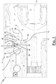
- 1 denotes, in its entirety, a wheel hub-bearing/constant-velocity joint unit for transmitting a rotary motion about an axis A from a half-shaft 2 engaged in the constant-velocity joint 3 to a wheel (not shown) supported by the wheel hub/bearing assembly 4, which comprises a bearing 5 provided with an outer ring 6 mounted in a post 7 and with an inner ring 8, which is preferably but not necessarily flanged so as to support the wheel (not shown).
- the constant-velocity joint 3 is laterally delimited by an outer cylindrical surface 9 and is provided with a grooved shaft 10, which extends axially from a side wall 11 of said constant-velocity joint 3 and engages into the inner ring 8 so as to rotate with said inner ring 8 about the axis A.
- the bearing 5 is, in addition, provided with a sealing device 12 interposed between the outer ring 6 and the inner ring 8 so as to close an annular gap 13 defined by the two rings 6 and 8 and to protect the bearing 5 against the admission of external agents such as, for example, powder, sand, dirt or water.
- the inner ring 8 of the bearing 5 also defines the hub of the assembly 1, and is also provided with a rolled rim 14 for axially blocking a so-called "small ring", that is a ring 15 provided with a respective raceway 16.
- the bearing 5 may also be of the type with two rows of rolling bodies mounted on a wheel hub, or else may also not have the rolled rim 14, despite the small ring 15 being axially blocked.
- the unit 1 comprises, in addition, a protective screen 20, which is mounted on the outer cylindrical surface 9 of the constant-velocity joint 3 against the side wall 11 in a position which is axially opposite the sealing device 12 for protecting the sealing device 12 and the rolling-contact bearing 5 from the action of external agents, and, as is also shown in Figures 2 and 3 , is provided with an annular wall 21, which is arranged transversely to the axis A and in axial abutment against the side wall 11, and with a central hole 22, which is made through the annular wall 21 and through which the shaft 10 of the constant-velocity joint 3 passes with play.
- the screen 20 is made of metallic sheet material or, preferably, can be made of plastic material, and comprises a plurality of elastic mounting and centring fins 23, which are distributed uniformly about the central hole 22 and extend unsupported from the annular wall 21 such that they are coupled to the outer cylindrical surface 9 of the constant-velocity joint 3.
- the fins 23 are obtained by cutting the annular wall 21, defining respective windows 24, and are arranged in a substantially perpendicular manner with respect to the annular wall 21.
- the elasticity of the fins 23 not only keeps the screen 5 joined to the constant-velocity joint 3, but also makes it possible to compensate for possible differences presented by the outer cylindrical surface 9, giving the screen 5 suitable characteristics so that it can also possibly be assembled with the unit 1 like a spare part, or on constant-velocity joints 3 originating from third party suppliers.
- the fins 23 have an end extension 25 bent slightly towards the outside of the axis A in order to act as an introduction bevel for said fins 23.
- the elastic fins 23 would instead be obtained by moulding, that is during the same moulding of the screen 20.
- the screen 20 is provided with five fins 23 distributed uniformly about the axis A.
- the number of fins 23 may, however, also be greater than five and may be selected depending on the dimensions of the screen 20 and of the constant-velocity joint 3.
- the fins 23 have centring functions for the screen 20 with respect to the axis A and to the constant-velocity joint 3, and also allow for the screen 20 to be mounted on the constant-velocity joint 3 and for the totally safe movement of the latter without the possibility of accidental separation of the two components.
- the protective screen 20 comprises, in addition, a deflector 26, which is integral with the annular wall 21 and extends radially towards the outside of said annular wall 21 and towards an inner surface 7a of the post 7 so as to define an annular through-channel 27 of very limited dimensions which are, in any case, inadequate for the passage of large quantities of water or dirt or other debris such as can damage the sealing device 12 when these external agents are conveyed directly against said sealing device 12.
- the deflector 26 has a substantially conical shape with a conicity which tapers towards the bearing 5 so as to act, when in rotation with the constant-velocity joint 3 about the axis A, like a centrifuge for external agents at a large distance from the bearing 5.
- the screen 20 rotates, in use, about the axis A together with the constant-velocity joint 3 and with the inner ring 8, and the rotation thereof brings about the centrifuging of any fluids or debris which may be in contact with said screen 20 or may be located in the immediate vicinity thereof.
- the shape of the deflector 26 makes it possible for any fluids or debris to be conveyed against the post 7 in an axially opposed direction with respect to the bearing 5, providing for an effective and efficient protective action, both dynamic and static, for said bearing 5 and for the relative sealing device 12.
- the annular wall 21 comprises an annular rim 28, which radially outwardly delimits the central hole 22 and is in turn radially outwardly delimited by the elastic fins 23.
- the annular rim 28 is axially compressed between the bearing 5 and the side wall 11 of the constant-velocity joint 3 so as to make the screen 20 angularly integral with the inner ring 8 of the bearing 5 and with the constant-velocity joint 3 during rotation about the axis A.
- the dual clamping action exerted on the rim 28 by the bearing 5 from one side and by the constant-velocity joint 3 from an opposite side is exerted when the mounting of the unit 1 has been completed, that is when the shaft 10 and the inner ring 8 are axially closed with respect to one another by means, for example, of a screw (not shown).
- the clamping of the shaft 10 and of the inner ring 8 and the consequent axial compression of the annular rim 28 ensure that the screen 20 rotates about the axis A together with the inner ring 8 of the bearing 5 and with the constant-velocity joint 3.
- the annular rim 28 is axially compressed between said rim 14 and the side wall 11 of the joint.
- the side wall 21 has a flat shape inasmuch as the rolled rim 14 positions the screen 5 at an axial distance from the sealing device 12 which is equal to an axial dimension of said rolled rim 14.
- the bearing 5 is not provided with the rolled rim 14, the screen 20 nevertheless remains blocked and angularly integral with the inner ring 8 of the bearing 5 and with the constant-velocity joint 3 during rotation about the axis A, but it is necessary to establish an axial positioning thickness between the sealing device 12 and the screen 5 in order to avoid relative instances of rubbing between the screen 20 and the fixed parts of the sealing device 10 or else of said bearing 5.
- Said axial positioning thickness is established either by turning the annular rim 28 on itself, in the case in which the screen 20 is made of metallic sheet material, or by forming the annular rim 28 with an axial thickness which is at least greater than an axial thickness of the annular wall 21, when the screen 20 is made of plastic material.
- the annular wall 21 may have a rib substantially in the proximity of the connections of the fins 23 so as to axially offset the annular wall 21 with respect to the rim 28 from the part of said fins 23.
- the sealing device 12 is composed of two screens 31 and 32 respectively mounted in the outer ring 6 and on the inner ring 8 and of a lip 33 interposed between the two screens 31 and 32.
- the sealing device 12 may also comprise at least one further sealing lip 34, which is supported by a mounting flange 35 forming part of the screen 32 and extends axially outside the inner ring 8 in such a way as to extend axially beyond the rolled rim 14 until it comes into contact with the annular wall 21 substantially at the annular rim 28.
- the lip 34 makes it possible to seal off at least part of the annular rim 28 from the outside and, in addition, makes it possible to seal off the area of coupling between the inner ring 8 and the shaft 10 from the outside.
- the lip 34 has two free end portions 35 and 36, of which the portion 35 makes direct contact with the screen 20, whereas the portion 36 is arranged more to the inside towards the axis A with respect to the portion 35 and makes contact with the rolled rim 14: the dual contact, in addition to defining dedicated protection both for the rim 28 and for the rim 14, increases the sealing and protective capacity of the sealing device 10.
- the protective screen 5 described above, and in the variants described above, has a high level of versatility and can be adapted so as to be coupled to different constant-velocity joints 3, while at the same time making it possible to enhance the protective characteristics for the unit 1 as described above.
Landscapes
- Engineering & Computer Science (AREA)
- General Engineering & Computer Science (AREA)
- Mechanical Engineering (AREA)
- Sealing Devices (AREA)
- Rolling Contact Bearings (AREA)
- Sealing Of Bearings (AREA)
Applications Claiming Priority (1)
| Application Number | Priority Date | Filing Date | Title |
|---|---|---|---|
| IT000697A ITTO20110697A1 (it) | 2011-07-29 | 2011-07-29 | Schermo di protezione per giunti omocinetici ed unità cuscinetto mozzo ruota-giunto omocinetico provvista di tale schermo di protezione |
Publications (2)
| Publication Number | Publication Date |
|---|---|
| EP2551542A1 EP2551542A1 (en) | 2013-01-30 |
| EP2551542B1 true EP2551542B1 (en) | 2019-05-15 |
Family
ID=44584482
Family Applications (1)
| Application Number | Title | Priority Date | Filing Date |
|---|---|---|---|
| EP12175802.3A Active EP2551542B1 (en) | 2011-07-29 | 2012-07-10 | Wheel-hub bearing/constant-velocity joint unit provided with a protective screen |
Country Status (3)
| Country | Link |
|---|---|
| US (1) | US8808099B2 (it) |
| EP (1) | EP2551542B1 (it) |
| IT (1) | ITTO20110697A1 (it) |
Families Citing this family (1)
| Publication number | Priority date | Publication date | Assignee | Title |
|---|---|---|---|---|
| JP2022069254A (ja) * | 2020-10-23 | 2022-05-11 | 株式会社Subaru | 密封装置 |
Family Cites Families (9)
| Publication number | Priority date | Publication date | Assignee | Title |
|---|---|---|---|---|
| FR2703740B1 (fr) * | 1993-04-09 | 1995-05-24 | Roulements Soc Nouvelle | Roulement équipé d'un dispositif capteur d'informations. |
| DE4319168C2 (de) * | 1993-06-09 | 1995-08-17 | Freudenberg Carl Fa | Torsionsschwingungsdämpfer |
| JP3585339B2 (ja) * | 1997-03-18 | 2004-11-04 | 株式会社エクセディ | 多板クラッチ |
| JP3982093B2 (ja) * | 1998-02-16 | 2007-09-26 | 日本精工株式会社 | 車輪駆動用車軸ユニット |
| JP4691851B2 (ja) * | 2001-08-07 | 2011-06-01 | 株式会社ジェイテクト | 車軸用軸受装置 |
| JP2006064082A (ja) | 2004-08-27 | 2006-03-09 | Jtekt Corp | 転がり軸受装置 |
| WO2006073159A1 (ja) * | 2005-01-07 | 2006-07-13 | Honda Motor Co., Ltd. | 駆動輪用軸受装置 |
| EP2103451B1 (en) * | 2006-12-28 | 2016-03-09 | JTEKT Corporation | Wheel supporting device |
| ATE500977T1 (de) * | 2007-01-04 | 2011-03-15 | Skf Ab | Dichtungsanordnung zwischen einem gleichlaufgelenk und einer nabenlagereinheit eines kraftfahrzeugrades |
-
2011
- 2011-07-29 IT IT000697A patent/ITTO20110697A1/it unknown
-
2012
- 2012-07-10 EP EP12175802.3A patent/EP2551542B1/en active Active
- 2012-07-17 US US13/550,704 patent/US8808099B2/en active Active
Non-Patent Citations (1)
| Title |
|---|
| None * |
Also Published As
| Publication number | Publication date |
|---|---|
| US20130184086A1 (en) | 2013-07-18 |
| ITTO20110697A1 (it) | 2013-01-30 |
| EP2551542A1 (en) | 2013-01-30 |
| US8808099B2 (en) | 2014-08-19 |
Similar Documents
| Publication | Publication Date | Title |
|---|---|---|
| JP5901632B2 (ja) | 転がり軸受用のシールアセンブリ | |
| EP2685118B1 (en) | Wheel hub rolling bearing assembly for a motor vehicle with a sealing device | |
| US20150071581A1 (en) | Preassembled insertable roller bearing unit | |
| KR101411615B1 (ko) | 씰링 장치 및 이를 이용한 휠 베어링 조립체 | |
| EP3985271B1 (en) | Sealing device | |
| US7628541B2 (en) | Sealing device for a wheel hub unit | |
| US8657503B2 (en) | Bearing hub unit for a motor-vehicle wheel | |
| JP2010060127A (ja) | 転がり軸受装置 | |
| CN210978234U (zh) | 带密封装置的轮毂单元轴承 | |
| US8061901B2 (en) | Extension member for a flinger of a bearing | |
| US9662937B2 (en) | Vehicle hub bearing unit provided with a protective ring | |
| EP2551542B1 (en) | Wheel-hub bearing/constant-velocity joint unit provided with a protective screen | |
| EP2800915B1 (en) | A large sealed self aligning roller bearing | |
| CN107975533B (zh) | 车轮用的轮毂轴承组件 | |
| KR101551892B1 (ko) | 실링 장치 및 이를 이용한 휠 베어링 조립체 | |
| WO2021059626A1 (ja) | 密封装置 | |
| US20210115973A1 (en) | Sealing device | |
| KR102075472B1 (ko) | 구름 베어링용 카트리지 씰 | |
| JP2012087901A (ja) | 密封装置および転がり軸受装置 | |
| JP2017106574A (ja) | 密封装置及び密封装置付ハブユニット軸受 | |
| JP2005325924A (ja) | 密封装置 | |
| JP6625340B2 (ja) | 密封装置 | |
| CN112277529B (zh) | 用于轮毂总成的密封装置 | |
| US6899463B2 (en) | Protection device for an encoder in a rolling bearing | |
| WO2021005882A1 (ja) | 密封装置および密封構造 |
Legal Events
| Date | Code | Title | Description |
|---|---|---|---|
| PUAI | Public reference made under article 153(3) epc to a published international application that has entered the european phase |
Free format text: ORIGINAL CODE: 0009012 |
|
| AK | Designated contracting states |
Kind code of ref document: A1 Designated state(s): AL AT BE BG CH CY CZ DE DK EE ES FI FR GB GR HR HU IE IS IT LI LT LU LV MC MK MT NL NO PL PT RO RS SE SI SK SM TR |
|
| AX | Request for extension of the european patent |
Extension state: BA ME |
|
| 17P | Request for examination filed |
Effective date: 20130730 |
|
| RBV | Designated contracting states (corrected) |
Designated state(s): AL AT BE BG CH CY CZ DE DK EE ES FI FR GB GR HR HU IE IS IT LI LT LU LV MC MK MT NL NO PL PT RO RS SE SI SK SM TR |
|
| GRAP | Despatch of communication of intention to grant a patent |
Free format text: ORIGINAL CODE: EPIDOSNIGR1 |
|
| STAA | Information on the status of an ep patent application or granted ep patent |
Free format text: STATUS: GRANT OF PATENT IS INTENDED |
|
| INTG | Intention to grant announced |
Effective date: 20181211 |
|
| GRAS | Grant fee paid |
Free format text: ORIGINAL CODE: EPIDOSNIGR3 |
|
| GRAA | (expected) grant |
Free format text: ORIGINAL CODE: 0009210 |
|
| STAA | Information on the status of an ep patent application or granted ep patent |
Free format text: STATUS: THE PATENT HAS BEEN GRANTED |
|
| AK | Designated contracting states |
Kind code of ref document: B1 Designated state(s): AL AT BE BG CH CY CZ DE DK EE ES FI FR GB GR HR HU IE IS IT LI LT LU LV MC MK MT NL NO PL PT RO RS SE SI SK SM TR |
|
| REG | Reference to a national code |
Ref country code: CH Ref legal event code: EP Ref country code: GB Ref legal event code: FG4D |
|
| REG | Reference to a national code |
Ref country code: DE Ref legal event code: R096 Ref document number: 602012060089 Country of ref document: DE |
|
| REG | Reference to a national code |
Ref country code: IE Ref legal event code: FG4D |
|
| REG | Reference to a national code |
Ref country code: NL Ref legal event code: MP Effective date: 20190515 |
|
| REG | Reference to a national code |
Ref country code: LT Ref legal event code: MG4D |
|
| PG25 | Lapsed in a contracting state [announced via postgrant information from national office to epo] |
Ref country code: HR Free format text: LAPSE BECAUSE OF FAILURE TO SUBMIT A TRANSLATION OF THE DESCRIPTION OR TO PAY THE FEE WITHIN THE PRESCRIBED TIME-LIMIT Effective date: 20190515 Ref country code: NL Free format text: LAPSE BECAUSE OF FAILURE TO SUBMIT A TRANSLATION OF THE DESCRIPTION OR TO PAY THE FEE WITHIN THE PRESCRIBED TIME-LIMIT Effective date: 20190515 Ref country code: LT Free format text: LAPSE BECAUSE OF FAILURE TO SUBMIT A TRANSLATION OF THE DESCRIPTION OR TO PAY THE FEE WITHIN THE PRESCRIBED TIME-LIMIT Effective date: 20190515 Ref country code: ES Free format text: LAPSE BECAUSE OF FAILURE TO SUBMIT A TRANSLATION OF THE DESCRIPTION OR TO PAY THE FEE WITHIN THE PRESCRIBED TIME-LIMIT Effective date: 20190515 Ref country code: FI Free format text: LAPSE BECAUSE OF FAILURE TO SUBMIT A TRANSLATION OF THE DESCRIPTION OR TO PAY THE FEE WITHIN THE PRESCRIBED TIME-LIMIT Effective date: 20190515 Ref country code: NO Free format text: LAPSE BECAUSE OF FAILURE TO SUBMIT A TRANSLATION OF THE DESCRIPTION OR TO PAY THE FEE WITHIN THE PRESCRIBED TIME-LIMIT Effective date: 20190815 Ref country code: PT Free format text: LAPSE BECAUSE OF FAILURE TO SUBMIT A TRANSLATION OF THE DESCRIPTION OR TO PAY THE FEE WITHIN THE PRESCRIBED TIME-LIMIT Effective date: 20190915 Ref country code: AL Free format text: LAPSE BECAUSE OF FAILURE TO SUBMIT A TRANSLATION OF THE DESCRIPTION OR TO PAY THE FEE WITHIN THE PRESCRIBED TIME-LIMIT Effective date: 20190515 Ref country code: SE Free format text: LAPSE BECAUSE OF FAILURE TO SUBMIT A TRANSLATION OF THE DESCRIPTION OR TO PAY THE FEE WITHIN THE PRESCRIBED TIME-LIMIT Effective date: 20190515 |
|
| PG25 | Lapsed in a contracting state [announced via postgrant information from national office to epo] |
Ref country code: BG Free format text: LAPSE BECAUSE OF FAILURE TO SUBMIT A TRANSLATION OF THE DESCRIPTION OR TO PAY THE FEE WITHIN THE PRESCRIBED TIME-LIMIT Effective date: 20190815 Ref country code: GR Free format text: LAPSE BECAUSE OF FAILURE TO SUBMIT A TRANSLATION OF THE DESCRIPTION OR TO PAY THE FEE WITHIN THE PRESCRIBED TIME-LIMIT Effective date: 20190816 Ref country code: LV Free format text: LAPSE BECAUSE OF FAILURE TO SUBMIT A TRANSLATION OF THE DESCRIPTION OR TO PAY THE FEE WITHIN THE PRESCRIBED TIME-LIMIT Effective date: 20190515 Ref country code: RS Free format text: LAPSE BECAUSE OF FAILURE TO SUBMIT A TRANSLATION OF THE DESCRIPTION OR TO PAY THE FEE WITHIN THE PRESCRIBED TIME-LIMIT Effective date: 20190515 |
|
| REG | Reference to a national code |
Ref country code: AT Ref legal event code: MK05 Ref document number: 1133788 Country of ref document: AT Kind code of ref document: T Effective date: 20190515 |
|
| PG25 | Lapsed in a contracting state [announced via postgrant information from national office to epo] |
Ref country code: AT Free format text: LAPSE BECAUSE OF FAILURE TO SUBMIT A TRANSLATION OF THE DESCRIPTION OR TO PAY THE FEE WITHIN THE PRESCRIBED TIME-LIMIT Effective date: 20190515 Ref country code: EE Free format text: LAPSE BECAUSE OF FAILURE TO SUBMIT A TRANSLATION OF THE DESCRIPTION OR TO PAY THE FEE WITHIN THE PRESCRIBED TIME-LIMIT Effective date: 20190515 Ref country code: RO Free format text: LAPSE BECAUSE OF FAILURE TO SUBMIT A TRANSLATION OF THE DESCRIPTION OR TO PAY THE FEE WITHIN THE PRESCRIBED TIME-LIMIT Effective date: 20190515 Ref country code: CZ Free format text: LAPSE BECAUSE OF FAILURE TO SUBMIT A TRANSLATION OF THE DESCRIPTION OR TO PAY THE FEE WITHIN THE PRESCRIBED TIME-LIMIT Effective date: 20190515 Ref country code: SK Free format text: LAPSE BECAUSE OF FAILURE TO SUBMIT A TRANSLATION OF THE DESCRIPTION OR TO PAY THE FEE WITHIN THE PRESCRIBED TIME-LIMIT Effective date: 20190515 Ref country code: DK Free format text: LAPSE BECAUSE OF FAILURE TO SUBMIT A TRANSLATION OF THE DESCRIPTION OR TO PAY THE FEE WITHIN THE PRESCRIBED TIME-LIMIT Effective date: 20190515 |
|
| REG | Reference to a national code |
Ref country code: DE Ref legal event code: R097 Ref document number: 602012060089 Country of ref document: DE |
|
| PG25 | Lapsed in a contracting state [announced via postgrant information from national office to epo] |
Ref country code: SM Free format text: LAPSE BECAUSE OF FAILURE TO SUBMIT A TRANSLATION OF THE DESCRIPTION OR TO PAY THE FEE WITHIN THE PRESCRIBED TIME-LIMIT Effective date: 20190515 Ref country code: IT Free format text: LAPSE BECAUSE OF FAILURE TO SUBMIT A TRANSLATION OF THE DESCRIPTION OR TO PAY THE FEE WITHIN THE PRESCRIBED TIME-LIMIT Effective date: 20190515 Ref country code: MC Free format text: LAPSE BECAUSE OF FAILURE TO SUBMIT A TRANSLATION OF THE DESCRIPTION OR TO PAY THE FEE WITHIN THE PRESCRIBED TIME-LIMIT Effective date: 20190515 |
|
| REG | Reference to a national code |
Ref country code: CH Ref legal event code: PL |
|
| PLBE | No opposition filed within time limit |
Free format text: ORIGINAL CODE: 0009261 |
|
| STAA | Information on the status of an ep patent application or granted ep patent |
Free format text: STATUS: NO OPPOSITION FILED WITHIN TIME LIMIT |
|
| PG25 | Lapsed in a contracting state [announced via postgrant information from national office to epo] |
Ref country code: TR Free format text: LAPSE BECAUSE OF FAILURE TO SUBMIT A TRANSLATION OF THE DESCRIPTION OR TO PAY THE FEE WITHIN THE PRESCRIBED TIME-LIMIT Effective date: 20190515 |
|
| REG | Reference to a national code |
Ref country code: BE Ref legal event code: MM Effective date: 20190731 |
|
| 26N | No opposition filed |
Effective date: 20200218 |
|
| GBPC | Gb: european patent ceased through non-payment of renewal fee |
Effective date: 20190815 |
|
| PG25 | Lapsed in a contracting state [announced via postgrant information from national office to epo] |
Ref country code: PL Free format text: LAPSE BECAUSE OF FAILURE TO SUBMIT A TRANSLATION OF THE DESCRIPTION OR TO PAY THE FEE WITHIN THE PRESCRIBED TIME-LIMIT Effective date: 20190515 |
|
| PG25 | Lapsed in a contracting state [announced via postgrant information from national office to epo] |
Ref country code: LU Free format text: LAPSE BECAUSE OF NON-PAYMENT OF DUE FEES Effective date: 20190710 Ref country code: LI Free format text: LAPSE BECAUSE OF NON-PAYMENT OF DUE FEES Effective date: 20190731 Ref country code: CH Free format text: LAPSE BECAUSE OF NON-PAYMENT OF DUE FEES Effective date: 20190731 Ref country code: SI Free format text: LAPSE BECAUSE OF FAILURE TO SUBMIT A TRANSLATION OF THE DESCRIPTION OR TO PAY THE FEE WITHIN THE PRESCRIBED TIME-LIMIT Effective date: 20190515 Ref country code: BE Free format text: LAPSE BECAUSE OF NON-PAYMENT OF DUE FEES Effective date: 20190731 |
|
| PG25 | Lapsed in a contracting state [announced via postgrant information from national office to epo] |
Ref country code: FR Free format text: LAPSE BECAUSE OF NON-PAYMENT OF DUE FEES Effective date: 20190715 |
|
| PG25 | Lapsed in a contracting state [announced via postgrant information from national office to epo] |
Ref country code: IE Free format text: LAPSE BECAUSE OF NON-PAYMENT OF DUE FEES Effective date: 20190710 |
|
| PG25 | Lapsed in a contracting state [announced via postgrant information from national office to epo] |
Ref country code: GB Free format text: LAPSE BECAUSE OF NON-PAYMENT OF DUE FEES Effective date: 20190815 |
|
| PG25 | Lapsed in a contracting state [announced via postgrant information from national office to epo] |
Ref country code: CY Free format text: LAPSE BECAUSE OF FAILURE TO SUBMIT A TRANSLATION OF THE DESCRIPTION OR TO PAY THE FEE WITHIN THE PRESCRIBED TIME-LIMIT Effective date: 20190515 |
|
| PG25 | Lapsed in a contracting state [announced via postgrant information from national office to epo] |
Ref country code: IS Free format text: LAPSE BECAUSE OF FAILURE TO SUBMIT A TRANSLATION OF THE DESCRIPTION OR TO PAY THE FEE WITHIN THE PRESCRIBED TIME-LIMIT Effective date: 20190915 |
|
| PG25 | Lapsed in a contracting state [announced via postgrant information from national office to epo] |
Ref country code: MT Free format text: LAPSE BECAUSE OF FAILURE TO SUBMIT A TRANSLATION OF THE DESCRIPTION OR TO PAY THE FEE WITHIN THE PRESCRIBED TIME-LIMIT Effective date: 20190515 Ref country code: HU Free format text: LAPSE BECAUSE OF FAILURE TO SUBMIT A TRANSLATION OF THE DESCRIPTION OR TO PAY THE FEE WITHIN THE PRESCRIBED TIME-LIMIT; INVALID AB INITIO Effective date: 20120710 |
|
| PG25 | Lapsed in a contracting state [announced via postgrant information from national office to epo] |
Ref country code: MK Free format text: LAPSE BECAUSE OF FAILURE TO SUBMIT A TRANSLATION OF THE DESCRIPTION OR TO PAY THE FEE WITHIN THE PRESCRIBED TIME-LIMIT Effective date: 20190515 |
|
| P01 | Opt-out of the competence of the unified patent court (upc) registered |
Effective date: 20230513 |
|
| PGFP | Annual fee paid to national office [announced via postgrant information from national office to epo] |
Ref country code: DE Payment date: 20230726 Year of fee payment: 12 |