EP2551435A2 - Autonomes Öffnungs- und Schließsystem für Klappflügel, und mit einem solchen System ausgestattete Anlage - Google Patents
Autonomes Öffnungs- und Schließsystem für Klappflügel, und mit einem solchen System ausgestattete Anlage Download PDFInfo
- Publication number
- EP2551435A2 EP2551435A2 EP12178064A EP12178064A EP2551435A2 EP 2551435 A2 EP2551435 A2 EP 2551435A2 EP 12178064 A EP12178064 A EP 12178064A EP 12178064 A EP12178064 A EP 12178064A EP 2551435 A2 EP2551435 A2 EP 2551435A2
- Authority
- EP
- European Patent Office
- Prior art keywords
- actuator
- leaf
- shaft
- telescopic bar
- opening
- Prior art date
- Legal status (The legal status is an assumption and is not a legal conclusion. Google has not performed a legal analysis and makes no representation as to the accuracy of the status listed.)
- Granted
Links
- 238000009434 installation Methods 0.000 title claims abstract description 35
- 230000033001 locomotion Effects 0.000 claims description 9
- 238000004891 communication Methods 0.000 claims description 8
- 230000006854 communication Effects 0.000 claims description 8
- 238000005096 rolling process Methods 0.000 claims description 6
- 230000036961 partial effect Effects 0.000 claims description 5
- 238000012790 confirmation Methods 0.000 claims description 4
- 230000000694 effects Effects 0.000 claims description 3
- 210000003462 vein Anatomy 0.000 claims 1
- XAGFODPZIPBFFR-UHFFFAOYSA-N aluminium Chemical compound [Al] XAGFODPZIPBFFR-UHFFFAOYSA-N 0.000 abstract description 2
- 229910052782 aluminium Inorganic materials 0.000 abstract description 2
- 239000002023 wood Substances 0.000 abstract description 2
- 239000000470 constituent Substances 0.000 description 8
- 238000006073 displacement reaction Methods 0.000 description 6
- 230000001965 increasing effect Effects 0.000 description 6
- 238000013519 translation Methods 0.000 description 5
- 230000000670 limiting effect Effects 0.000 description 4
- 230000009471 action Effects 0.000 description 3
- 238000006243 chemical reaction Methods 0.000 description 3
- 230000000295 complement effect Effects 0.000 description 3
- 238000001514 detection method Methods 0.000 description 3
- 230000003287 optical effect Effects 0.000 description 3
- 230000000254 damaging effect Effects 0.000 description 2
- 230000009975 flexible effect Effects 0.000 description 2
- 238000009413 insulation Methods 0.000 description 2
- 230000005291 magnetic effect Effects 0.000 description 2
- 239000000463 material Substances 0.000 description 2
- 230000004224 protection Effects 0.000 description 2
- 230000002829 reductive effect Effects 0.000 description 2
- 230000002441 reversible effect Effects 0.000 description 2
- 230000003068 static effect Effects 0.000 description 2
- 230000008901 benefit Effects 0.000 description 1
- 239000004917 carbon fiber Substances 0.000 description 1
- 230000015556 catabolic process Effects 0.000 description 1
- 239000003638 chemical reducing agent Substances 0.000 description 1
- 238000010276 construction Methods 0.000 description 1
- 230000008602 contraction Effects 0.000 description 1
- 230000006378 damage Effects 0.000 description 1
- 238000006731 degradation reaction Methods 0.000 description 1
- 238000013461 design Methods 0.000 description 1
- 238000005553 drilling Methods 0.000 description 1
- 229920001971 elastomer Polymers 0.000 description 1
- 239000000806 elastomer Substances 0.000 description 1
- 239000011152 fibreglass Substances 0.000 description 1
- 230000001976 improved effect Effects 0.000 description 1
- VNWKTOKETHGBQD-UHFFFAOYSA-N methane Chemical compound C VNWKTOKETHGBQD-UHFFFAOYSA-N 0.000 description 1
- 230000007935 neutral effect Effects 0.000 description 1
- 230000035515 penetration Effects 0.000 description 1
- 230000000284 resting effect Effects 0.000 description 1
- 230000011664 signaling Effects 0.000 description 1
- 230000008093 supporting effect Effects 0.000 description 1
- 230000001360 synchronised effect Effects 0.000 description 1
- XLYOFNOQVPJJNP-UHFFFAOYSA-N water Substances O XLYOFNOQVPJJNP-UHFFFAOYSA-N 0.000 description 1
- 229910001868 water Inorganic materials 0.000 description 1
Images



Classifications
-
- E—FIXED CONSTRUCTIONS
- E05—LOCKS; KEYS; WINDOW OR DOOR FITTINGS; SAFES
- E05F—DEVICES FOR MOVING WINGS INTO OPEN OR CLOSED POSITION; CHECKS FOR WINGS; WING FITTINGS NOT OTHERWISE PROVIDED FOR, CONCERNED WITH THE FUNCTIONING OF THE WING
- E05F17/00—Special devices for shifting a plurality of wings operated simultaneously
- E05F17/004—Special devices for shifting a plurality of wings operated simultaneously for wings which abut when closed
-
- E—FIXED CONSTRUCTIONS
- E05—LOCKS; KEYS; WINDOW OR DOOR FITTINGS; SAFES
- E05F—DEVICES FOR MOVING WINGS INTO OPEN OR CLOSED POSITION; CHECKS FOR WINGS; WING FITTINGS NOT OTHERWISE PROVIDED FOR, CONCERNED WITH THE FUNCTIONING OF THE WING
- E05F15/00—Power-operated mechanisms for wings
- E05F15/60—Power-operated mechanisms for wings using electrical actuators
- E05F15/603—Power-operated mechanisms for wings using electrical actuators using rotary electromotors
- E05F15/611—Power-operated mechanisms for wings using electrical actuators using rotary electromotors for swinging wings
-
- E—FIXED CONSTRUCTIONS
- E05—LOCKS; KEYS; WINDOW OR DOOR FITTINGS; SAFES
- E05F—DEVICES FOR MOVING WINGS INTO OPEN OR CLOSED POSITION; CHECKS FOR WINGS; WING FITTINGS NOT OTHERWISE PROVIDED FOR, CONCERNED WITH THE FUNCTIONING OF THE WING
- E05F5/00—Braking devices, e.g. checks; Stops; Buffers
- E05F5/12—Braking devices, e.g. checks; Stops; Buffers specially for preventing the closing of a wing before another wing has been closed
-
- E—FIXED CONSTRUCTIONS
- E05—LOCKS; KEYS; WINDOW OR DOOR FITTINGS; SAFES
- E05Y—INDEXING SCHEME ASSOCIATED WITH SUBCLASSES E05D AND E05F, RELATING TO CONSTRUCTION ELEMENTS, ELECTRIC CONTROL, POWER SUPPLY, POWER SIGNAL OR TRANSMISSION, USER INTERFACES, MOUNTING OR COUPLING, DETAILS, ACCESSORIES, AUXILIARY OPERATIONS NOT OTHERWISE PROVIDED FOR, APPLICATION THEREOF
- E05Y2201/00—Constructional elements; Accessories therefor
- E05Y2201/40—Motors; Magnets; Springs; Weights; Accessories therefor
- E05Y2201/43—Motors
-
- E—FIXED CONSTRUCTIONS
- E05—LOCKS; KEYS; WINDOW OR DOOR FITTINGS; SAFES
- E05Y—INDEXING SCHEME ASSOCIATED WITH SUBCLASSES E05D AND E05F, RELATING TO CONSTRUCTION ELEMENTS, ELECTRIC CONTROL, POWER SUPPLY, POWER SIGNAL OR TRANSMISSION, USER INTERFACES, MOUNTING OR COUPLING, DETAILS, ACCESSORIES, AUXILIARY OPERATIONS NOT OTHERWISE PROVIDED FOR, APPLICATION THEREOF
- E05Y2201/00—Constructional elements; Accessories therefor
- E05Y2201/40—Motors; Magnets; Springs; Weights; Accessories therefor
- E05Y2201/43—Motors
- E05Y2201/434—Electromotors; Details thereof
-
- E—FIXED CONSTRUCTIONS
- E05—LOCKS; KEYS; WINDOW OR DOOR FITTINGS; SAFES
- E05Y—INDEXING SCHEME ASSOCIATED WITH SUBCLASSES E05D AND E05F, RELATING TO CONSTRUCTION ELEMENTS, ELECTRIC CONTROL, POWER SUPPLY, POWER SIGNAL OR TRANSMISSION, USER INTERFACES, MOUNTING OR COUPLING, DETAILS, ACCESSORIES, AUXILIARY OPERATIONS NOT OTHERWISE PROVIDED FOR, APPLICATION THEREOF
- E05Y2201/00—Constructional elements; Accessories therefor
- E05Y2201/60—Suspension or transmission members; Accessories therefor
- E05Y2201/604—Transmission members
-
- E—FIXED CONSTRUCTIONS
- E05—LOCKS; KEYS; WINDOW OR DOOR FITTINGS; SAFES
- E05Y—INDEXING SCHEME ASSOCIATED WITH SUBCLASSES E05D AND E05F, RELATING TO CONSTRUCTION ELEMENTS, ELECTRIC CONTROL, POWER SUPPLY, POWER SIGNAL OR TRANSMISSION, USER INTERFACES, MOUNTING OR COUPLING, DETAILS, ACCESSORIES, AUXILIARY OPERATIONS NOT OTHERWISE PROVIDED FOR, APPLICATION THEREOF
- E05Y2201/00—Constructional elements; Accessories therefor
- E05Y2201/60—Suspension or transmission members; Accessories therefor
- E05Y2201/606—Accessories therefor
- E05Y2201/62—Synchronisation of suspension or transmission members
-
- E—FIXED CONSTRUCTIONS
- E05—LOCKS; KEYS; WINDOW OR DOOR FITTINGS; SAFES
- E05Y—INDEXING SCHEME ASSOCIATED WITH SUBCLASSES E05D AND E05F, RELATING TO CONSTRUCTION ELEMENTS, ELECTRIC CONTROL, POWER SUPPLY, POWER SIGNAL OR TRANSMISSION, USER INTERFACES, MOUNTING OR COUPLING, DETAILS, ACCESSORIES, AUXILIARY OPERATIONS NOT OTHERWISE PROVIDED FOR, APPLICATION THEREOF
- E05Y2201/00—Constructional elements; Accessories therefor
- E05Y2201/60—Suspension or transmission members; Accessories therefor
- E05Y2201/622—Suspension or transmission members elements
- E05Y2201/686—Rods, links
-
- E—FIXED CONSTRUCTIONS
- E05—LOCKS; KEYS; WINDOW OR DOOR FITTINGS; SAFES
- E05Y—INDEXING SCHEME ASSOCIATED WITH SUBCLASSES E05D AND E05F, RELATING TO CONSTRUCTION ELEMENTS, ELECTRIC CONTROL, POWER SUPPLY, POWER SIGNAL OR TRANSMISSION, USER INTERFACES, MOUNTING OR COUPLING, DETAILS, ACCESSORIES, AUXILIARY OPERATIONS NOT OTHERWISE PROVIDED FOR, APPLICATION THEREOF
- E05Y2201/00—Constructional elements; Accessories therefor
- E05Y2201/60—Suspension or transmission members; Accessories therefor
- E05Y2201/622—Suspension or transmission members elements
- E05Y2201/708—Sliders
-
- E—FIXED CONSTRUCTIONS
- E05—LOCKS; KEYS; WINDOW OR DOOR FITTINGS; SAFES
- E05Y—INDEXING SCHEME ASSOCIATED WITH SUBCLASSES E05D AND E05F, RELATING TO CONSTRUCTION ELEMENTS, ELECTRIC CONTROL, POWER SUPPLY, POWER SIGNAL OR TRANSMISSION, USER INTERFACES, MOUNTING OR COUPLING, DETAILS, ACCESSORIES, AUXILIARY OPERATIONS NOT OTHERWISE PROVIDED FOR, APPLICATION THEREOF
- E05Y2600/00—Mounting or coupling arrangements for elements provided for in this subclass
- E05Y2600/40—Mounting location; Visibility of the elements
- E05Y2600/46—Mounting location; Visibility of the elements in or on the wing
-
- E—FIXED CONSTRUCTIONS
- E05—LOCKS; KEYS; WINDOW OR DOOR FITTINGS; SAFES
- E05Y—INDEXING SCHEME ASSOCIATED WITH SUBCLASSES E05D AND E05F, RELATING TO CONSTRUCTION ELEMENTS, ELECTRIC CONTROL, POWER SUPPLY, POWER SIGNAL OR TRANSMISSION, USER INTERFACES, MOUNTING OR COUPLING, DETAILS, ACCESSORIES, AUXILIARY OPERATIONS NOT OTHERWISE PROVIDED FOR, APPLICATION THEREOF
- E05Y2800/00—Details, accessories and auxiliary operations not otherwise provided for
- E05Y2800/37—Length, width or depth adjustment
- E05Y2800/372—Telescopically
-
- E—FIXED CONSTRUCTIONS
- E05—LOCKS; KEYS; WINDOW OR DOOR FITTINGS; SAFES
- E05Y—INDEXING SCHEME ASSOCIATED WITH SUBCLASSES E05D AND E05F, RELATING TO CONSTRUCTION ELEMENTS, ELECTRIC CONTROL, POWER SUPPLY, POWER SIGNAL OR TRANSMISSION, USER INTERFACES, MOUNTING OR COUPLING, DETAILS, ACCESSORIES, AUXILIARY OPERATIONS NOT OTHERWISE PROVIDED FOR, APPLICATION THEREOF
- E05Y2900/00—Application of doors, windows, wings or fittings thereof
- E05Y2900/10—Application of doors, windows, wings or fittings thereof for buildings or parts thereof
- E05Y2900/13—Type of wing
- E05Y2900/146—Shutters
-
- E—FIXED CONSTRUCTIONS
- E05—LOCKS; KEYS; WINDOW OR DOOR FITTINGS; SAFES
- E05Y—INDEXING SCHEME ASSOCIATED WITH SUBCLASSES E05D AND E05F, RELATING TO CONSTRUCTION ELEMENTS, ELECTRIC CONTROL, POWER SUPPLY, POWER SIGNAL OR TRANSMISSION, USER INTERFACES, MOUNTING OR COUPLING, DETAILS, ACCESSORIES, AUXILIARY OPERATIONS NOT OTHERWISE PROVIDED FOR, APPLICATION THEREOF
- E05Y2900/00—Application of doors, windows, wings or fittings thereof
- E05Y2900/10—Application of doors, windows, wings or fittings thereof for buildings or parts thereof
- E05Y2900/13—Type of wing
- E05Y2900/148—Windows
Definitions
- the present invention relates to an autonomous system for opening and closing wings, in particular for a double leaf opening system.
- the invention also relates to a double leaf opening system equipped with such a system, in particular a double-leaf window flap.
- the field of the invention is that of the actuator systems for the wing flaps.
- a double-leaf opening system comprises two wings hinged to the outer wall of a building, so as to obscure a window formed in this wall.
- the installation further comprises a leaf actuator system, preferably motorized.
- a motorized system comprises for example one or more arm drive motors articulated on the leaves.
- the motors are arranged in housings fixed to the masonry of the building or to the frame of the window, in particular by screwing.
- tenants may wish a removable motorized system to be able to transport it during a move.
- a removable motorized system must be easy to install and dismount without damaging the masonry.
- FR-A-2,638,779 describes a shutter opening and closing system, adapted to be installed without drilling the masonry.
- the system comprises a telescopic bar constituted by two tubes, provided with an internal spring exerting an action of extension on their free ends. These ends are hinged to each of the wings using support pieces fixed rigidly to the leaves, which is not satisfactory.
- the spring is sensitive to fatigue over time, which implies a risk of degradation of the operation of the system.
- the system includes a cord or chain to be manipulated by a user to move the leaves, thereby creating additional stress on the hinges of the leaves.
- the system has a problem of passage to neutral, when the telescopic bar passes a minimum distance.
- the object of the present invention is to provide an improved leaf actuator system, not having the disadvantages mentioned above.
- the subject of the invention is an autonomous system for opening and closing wings, adapted to equip a double-leaf opening system, the system comprising a telescopic bar including at least a first part and a second part. configured to extend or retract along a telescopic movement path between a first leaf and a second leaf.
- the system is characterized in that it also comprises a first actuator comprising a drive motor in rotation of a first shaft and fastening means to the first leaf, and a second actuator comprising a rotation drive motor. a second shaft and fastening means to the second leaf.
- the first part of the telescopic bar is integral with the first shaft driven by the motor of the first actuator and the second part of the telescopic bar is integral with the second shaft driven by the motor of the second actuator.
- the invention provides an opening and closing system with reduced complexity and cost, easy to install on a building door without damaging the masonry.
- the actuators exert torques on the shafts, which transmit these couples to the telescopic bar to cause its deployment or withdrawal, causing the opening or closing of the leaves.
- the drive is only "rotary", without the need for a cable, hydraulic or pneumatic device.
- the system operates without requiring a spring, sensitive to fatigue over time, between the parts of the telescopic bar.
- the hinges of the leaves are subjected to a pure torque, corresponding substantially to the engine torque, and do not undergo additional constraints. Thanks to the use of the telescopic bar, it is not necessary to synchronize the movements of the leaves with a complex and expensive electronic control. In addition, the motorization is distinct from the bar, which can thus have a free form. Finally, the system allows desynchronization of the leaves if necessary.
- the invention also relates to a double leaf opening system, characterized in that it is equipped with an autonomous system for opening and closing flaps as mentioned above.
- the installation is preferably a double-pane window pane, but can also be a gate, an entrance door or a garage door.
- FIG. 1 to 6 On the Figures 1 to 6 is shown a double flap shutter installation 10 equipping a window 3 formed in a building 1.
- the building 1 has an opening in a vertical outer wall 2, at the level of which is the window 3.
- Vertical walls 5 and 6 and horizontal 7 and 8 define the opening or frame 4 of the window 3.
- the window 3 is disposed towards the interior of the building 1 and comprises a glazed frame 9 which can be pivoted or sliding.
- the glazed frame 9 passes light and, to a certain extent, fulfills a function of sound and heat insulation.
- the installation 10 comprises a covered leaf 20 and a leaf covering 30 articulated on the outer wall 2 of the building 1, as well as a motorized system 40 for opening and closing the leaves 20 and 30.
- the installation 10 is specifically provided for to fulfill a function of thermal and sound insulation and solar protection for the occupants and the interior of the building 1, located on the other side of the window 3 and the window 9.
- the leaves 20 and 30 can be selectively actuated by the motorized system 40 to obscure or expose the window 3.
- Each leaf 20 and 30 is presented as a massive occultation panel, or provided with thin slots that can pass fine light strip type shutters.
- the leaves 20 and 30 can be made of any type of material, for example wood, aluminum or PVC.
- the covered leaf 20 comprises an end provided with hinges 21 fixed to the wall 2, as well as an end 22 opposite to the hinges 21.
- the covering leaf 30 comprises an end provided with hinges 31 fixed to the wall 2, as well as an end 32 opposite to these hinges 31.
- the ends 22 and 32 have complementary shapes, so that when the leaves 20 and 30 are closed, the end 22 may be covered by the end 32 but can not cover the end 22. In other words, we distinguish the covered end 22 and the covering end 32.
- the wing 20 is shown in an open position 26 to Figures 1 to 3 , in a closed position 28 to figures 4 and 6 , and in an intermediate position 27 to the figure 5 .
- the leaf 30 is shown in an open position 36 to Figures 1 to 3 in a closed position 38 at the figure 4 , and in intermediate positions 37a and 37b to Figures 5 and 6 .
- intermediate positions 27n and 37n of non-interference are shown in dashed lines at Figures 5 and 6 and will be detailed below. As their name indicates, the intermediate positions 27, 27n, 37a, 37b, 37n are located between the open positions 26 and 36 and the closed positions 28 and 38.
- the leaf 20 has a vertical face 23, facing outwards in the open position 26 and towards the interior of the building 1 in the closed position 28. On the face 23 are arranged horizontal bars 24, specifically an upper bar and a bar lower. The leaf 20 also has a horizontal upper edge 25, facing upwards. Similarly, the leaf 30 has a vertical face 33, horizontal bars 34 and an upper edge 35.
- the motorized system 40 for opening and closing the leaves 20 and 30 comprises a control device 42, an actuator 50 fixed on the face 23 of the leaf 20, an actuator 60 fixed on the face 33 of the wing 20, and a telescopic bar 70 which extends between the actuators 50 and 60.
- the actuators 50 and 60 coupled to the telescopic bar 70, make it possible to control the displacements wings 20 and 30 according to the instructions issued by the control device 42.
- the actuator 50 is a master actuator and the actuator 60 is a slave actuator.
- the control device 42 is schematically represented by a dotted block, located inside the building 1, with figures 1 and 3 .
- the device 42 is preferably a remote control unit, communicating by radio with the actuators 50 and 60, or at least the master actuator 50, in order to transmit to it commands from a user of the motorized system 40.
- the remote control may be replaced by a box with control buttons, eg attached to the interior wall of building 1, adjacent to window 3.
- Each actuator 50 and 60 comprises a housing, in which are housed in particular an electric battery, an electric motor, a gearbox, radio communication means, and an electronic control card of the engine according to the instructions received by the means of communication. radio communication.
- These constitutive elements of the actuators 50 and 60 are not represented in FIGS. Figures 1 to 6 for the sake of simplification.
- the fact that the actuators 50 and 60 comprise a battery and radio communication means is thus advantageous in terms of the mobility of the system 40, in particular for its assembly and disassembly.
- the system 40 is autonomous in energy.
- the casing of the actuator 50 has a horizontal upper face 51, through which a shaft 52 extends along a vertical axis A52.
- the housing of the actuator 60 has a horizontal upper face 61, through which a shaft 62 extends along a vertical axis A62.
- the actuator 50 is secured to the face 23 of the leaf 20 by a device 53 for removable attachment.
- the actuator 60 is secured to the face 33 of the leaf 30 by a device 63 for removable attachment.
- the actuators 50 and 60 are positioned on the leaves 20 and 30 so that the faces 51, 61 and the shafts 52, 62 are oriented upwards on the Figures 1 to 6 .
- the device 53 for fixing the actuator 50 to the leaf 20 is represented only in the Figures 1 to 3 , while the device 63 for fixing the actuator 60 to the leaf 30 is shown only at the figure 1 .
- the following description refers to the device 53, it being understood that the device 63 has a similar operation.
- the device 53 comprises hooks 54 and 55 which are fixed to the casing of the actuator 50, at the level of the face of the plated casing against the 23 of the flap 20.
- Each hook 54 and 55 extends upwardly from the actuator 50, is folded over the edge 25 of the leaf 20, and then behind the leaf 20, on the face opposite the face 23.
- the hooks 54 and 55 are hooked on the upper edge 25 of the leaf 20.
- the device 53 may include adjustment means, not shown, the length of the hooks 54 and 55 projecting beyond the face 51 of the actuator 50
- the device 53 also comprises two bearing pieces 56 and 57, respectively provided with tabs 56a and 57b and clamping screws 58 and 59.
- the tabs 56a extend laterally against the face 23, on either side of the hook. 54, while the screw 58 passing through the piece 56 can be screwed to press the hook 54 against this face 23.
- the tabs 57a extend laterally against the face 23, on either side of the hook 54, while that the screw 59 passing through the piece 57 can be screwed to press the hook 55 against this face 23.
- the tightening of the screws 58, 59 makes it possible to rigidly fix the hooks 54, 55 and the actuator 50 to the leaf 20, without piercing this leaf 20.
- the fixing made by means of the device 53 is removable, so that the actuator 50 can be easily detached from the leaf 20 by unscrewing the screws 58 and 59.
- the operation of the device 63 is similar for fixing the actuator 60 to the leaf 30.
- the actuators 50 and 60 can be hooked to the leaves 20 and 30 with simple tightening screws.
- the use of the devices 53 and 63 also has the advantage of not touching the frame of the window 3 if it is fragile or difficult to drill.
- the actuators 50 and 60 rest on the bars 24 and 34 near the edges 25 and 35, thus facilitating their vertical positioning.
- the actuators 50 and 60 are positioned as close as possible to the hinges, respectively 21 and 31, in order to minimize the forces transmitted to these hinges 21 and 31 during operation of the motorized system 40.
- the devices 53 and 63 may have a different construction, suitable for the present application.
- the devices 53 and 63 can be used to position the actuators 50 and 60 at any point of the leaves 20 and 30, on the side of their faces 23 and 33.
- the actuators 50 and 60 can be positioned in the lower part wings 20 and 30, with the faces 51, 61 and the shafts 52, 62 which are oriented downwards.
- the motor and the gearbox of the actuator 50 form a drive geared motor assembly of the shaft 52, which protrudes out of the housing at the face 51.
- the motor and the gearbox of the actuator 60 form a geared motor drive assembly of a shaft 62 which protrudes out of the housing at the face 61.
- the geared motor assemblies are reversible and the shafts 52 and 62 can pivot in one or the other direction of rotation, respectively corresponding to the closing or opening of the openings 20 and 30, about their respective axes A52 and A62.
- the motors provide a dynamic torque of the order of 20 Nm and a static torque of the order of 100 Nm.
- the dynamic torque is sufficient to cause the displacement of the leaves 20 and 30, while the static torque is well adapted to maintain them in the open position 26, 36, in the intermediate position or in the closed position 28, 38.
- each actuator 50 and 60 is supplied with electrical energy by independent power supply means, in particular a battery internal to the housing.
- the battery can be standalone or connected to an external power source.
- each actuator 50 and 60 can be powered by a solar panel disposed on the wall 2 of the building 1 and connected to its internal battery. These means of supplying energy are also not represented in Figures 1 to 6 .
- the actuators 50 and 60 also comprise disengaging means, not shown in FIGS. Figures 1 to 6 .
- uncoupling can be performed between the drive shaft of a motor and the shaft 52 or 62 integral with the bar 70, or at one of the stages of the reducer associated with the motor.
- the leaves can be operated manually if necessary, for example in case of bad weather, strong wind or insufficient power supply.
- the telescopic bar 70 extends between the shafts 52 and 62 along a horizontal axis A70.
- This axis A70 passes through the axes of rotation A52 and A62 of the shafts 52 and 62.
- this axis A70 is movable in the plane horizontal.
- the bar 70 comprises two parts 80 and 90 elongated parallel to the axis A70, integral respectively with the shafts 52 and 62, sliding on one another during the extension or retraction of the bar along axis A70.
- the axis A70 constitutes a telescopic displacement path of the portions 80 and 90 of the bar 70.
- the parts 80 and 90 are each a hollow section of rectangular section, cooperating with each other as detailed below.
- the portion 80 has an outer sliding face 81, a first longitudinal end 82, a second longitudinal end 84 and a longitudinal groove 85.
- the end 82 is provided with an orifice 83 for passage of the shaft 52, as well as locking means, not shown, of the shaft 52 in the orifice 83.
- the connection between the shaft 52 and the orifice 83, not shown in FIGS. Figures 1 to 6 for the sake of simplification, can be achieved by keying or by complementary shapes, for example square or hexagonal.
- the portion 80 and the shaft 52 are integral in rotation around the A52 axis.
- the end 84 opposite to the first end 82, supports a roller 86 movable in rotation about an axis A86 perpendicular to the axis A52.
- the groove 85 is formed between the inner space of the portion 80 and its outer face 81.
- the groove 85 extends from the end 84 towards the end 82, parallel to the axis A70.
- the length of the groove 85 is of the order of two thirds of the length of the portion 80, these lengths being measured parallel to the axis A70.
- the portion 90 is identical to the portion 80, in inverse symmetry with respect to a central point 75 of the bar 70 located on the axis A70.
- the portion 90 has an outer sliding face 91, a first longitudinal end 92 provided with an opening 93, and a second longitudinal end 94 supporting a roller 96.
- the portion 90 also comprises a longitudinal groove 95, shown in dotted line at the figure 3 , parallel to the groove 85.
- the axes A86, A96 are parallel to each other, parallel to the axes A52, A62 and perpendicular to the axis A70.
- one and the same telescopic bar 70 can be adapted for different window sizes 3.
- the motors be placed as close as possible to the hinges, respectively 21 and 31, the positioning of the actuators 50 and 60 can also be an adjustment element vis-à-vis the length (min / max) of the telescopic bar 70.
- the roller 86 rolls in the groove 95, the roller 96 rolls in the groove 85, while the surfaces 81 and 91 slide against each other.
- these elements 81, 85, 86, 91, 95, 96 constitute cooperation means between the parts 80 and 90, which are slidably connected with sliding against one another.
- the parts 80 and 90 are connected with partial interpenetration of one into the other, at the rollers 86 and 96 cooperating with the grooves, respectively 95 and 85.
- the rollers 86 and 96 allow the rolling guidance of Parts 80 and 90.
- the rollers 86 and 96 comprise bearings on which are mounted bearings made of a material adapted to limit friction in the grooves 85 and 95, for example elastomer.
- the shaft 52 has a rotational movement R1, in a trigonometric direction in plan view, around the vertical axis A52 and, at the same time, the shaft 62 has a rotational movement R2, in a clockwise direction in order to from above in the direction of rotation R1 about the vertical axis A62. Therefore, the motor torque supplied by the actuators 50 and 60 at each shaft 52 and 62 tends, on the one hand, to rotate the portion 80 in rotation about the axis A52 in the direction of rotation R1 and, on the other hand, to rotate the 90 part in rotation about the axis A62 in the direction of rotation R2. Because of the design of the telescopic bar 70, the portions 80 and 90 can not rotate, but only translate relative to each other.
- rollers 86 and 96 roll in the grooves 95 and 85 and the parts 80 and 90 are translated, with the ends 82 and 92 which are close to each other.
- This retraction, or contraction, of the telescopic bar 70 along the axis A70 causes the closing of the leaves 20 and 30, which pivot around their respective hinges 21 and 31.
- the speed of opening or closing of the leaf 20 is equal to the speed of rotation of the shaft 52, while the opening or closing speed of the leaf 30 is equal to the speed of rotation of the leaf. 62.
- the actuators 50 and 60 are configured so that the rotational speeds of the shafts 52 and 62 are equal. By way of non-limiting example, these speeds of rotation can be between 1 and 3 revolutions per minute.
- the movements, on the one hand, of translation of the portions 80 and 90 of the bar 70 and, on the other hand, of rotation of the leaves 20 and 30, have a very high fluidity.
- the opening phase of the wings 20 and 30 is performed continuously, while it is preferable to perform the closing phase in two stages.
- the motorized system 40 is configured to avoid potential mechanical interference between the ends 22 and 32 of the wings 20 and 30, as detailed below.
- an interference zone Z17 is defined in which mechanical interference can occur between the wings 20 and 30, in particular when they are closed.
- P0 is a vertical reference plane delimited by the wall 2 of the building 1.
- the outer surfaces of the leaves 20 and 30 in the closed positions 28 and 38 may be aligned in the plane P0, or be offset slightly recessed or projecting.
- the intermediate positions 27n and 37n correspond to non-interference limit positions between the leaves 20 and 30. In these positions 27n and 37n, the leaves 20 and 30 delimit the interference zone Z17 between them and the plane P0.
- the motorized system 40 may be configured with a zone Z17 wider than its theoretical limits.
- the zone Z17 stored by the motorized system 30 is then delimited by positions 27n and 37n more inclined relative to the plane P0 than necessary to avoid interference.
- the device 42 transmits a closing instruction to the master actuator 50, which in turn transmits an intermediate closing instruction to the slave actuator 60.
- the actuators 50 and 60 begin almost simultaneously to close the two leaves 20 and 30.
- the action of the telescopic bar 70 rotates the leaves 20 and 30 around their respective hinges 21 and 31, with the ends 22 and 32 which are close to one of the 'other.
- the actuator 50 and the bar 70 close the leaf 20 to the closed position 28, in uninterrupted rotational movement under normal operating conditions.
- the actuator 60 and the bar 70 close the wing 30 only to the intermediate position 37n, in order to avoid any potential interference in the zone Z17.
- the rotation of the shaft 62 is stopped and the flap 30 is held in the intermediate position 37n, at the edge of the zone Z17.
- the axis A70 of the bar 70 is no longer parallel to the plane P0 and the window 3, but slightly inclined.
- the actuator 50 transmits a complete closing instruction to the actuator 60.
- the actuator 60 controls the rotation of the shaft 62, causing translation of the roller 96 in the groove 85 and the rotation of the leaf 20 to the closed position 28.
- the sash installation 10 then occults the window 3, with the covering end 32 which covers the covered end 22, as represented at figure 4 .
- the device 42 transmits an opening instruction to the master actuator 50, which in turn transmits an opening instruction to the slave actuator 60.
- the actuators 50 and 60 begin almost simultaneously to open the two leaves 20 and 30.
- the action of the telescopic bar 70 rotates the leaves 20 and 30 around their respective hinges 21 and 31, with the covered end 22 of the leaf 20 which follows the covering end 32 of the flapping 30, without possible interference.
- the leaves 20 and 30 can be controlled by the implementation of a unidirectional radio communication protocol, simple and inexpensive, with setpoint signals issued without confirmation of their receipt in return.
- the movements of the leaves 20 and 30 can be synchronized by the motorized system 40 without interference or desynchronization problem.
- the device 42 can be configured to transmit a closing instruction to each of the actuators 50 and 60, causing a different reaction for each of the actuators 50 and 60.
- the actuator 50 closes the door 20 until in the closed position 28, while the actuator 60 closes the wing 30 only to the intermediate position 37n, bordering the zone Z17 potential interference.
- the device 42 is configured to transmit an opening instruction to each of the actuators 50 and 60, and not only to the master actuator 50 which retransmits the instruction to the slave actuator 60.
- the motor of the corresponding actuator 50 or 60 can be stopped automatically, for safety reasons.
- the actuators 50 and 60 can then be disengaged and the flaps 20 and 30 flap can be closed or opened manually, with the portions 80 and 90 of the bar 70 which are freely translatable relative to each other.
- the sliding of a magnetic brake not shown, integrated with the actuators 50 and 60 can then occur.
- the devices 53, 63 for removable fixing and the telescopic bar 70 are presented as easy to implement accessories with the actuators 50 and 60, to form the motorized system 40.
- the system 40 has a bulk e40, in a dimension perpendicular to the plane P0, which is reduced in the closed configuration, in the space between the window 5 and the leaves 20 and 30.
- this space e40 measured in the horizontal direction perpendicular to the plane P0, is of the order of 45 millimeters.
- both actuators 50 and 60 must therefore be able to stop their engines in the final positions of opening and closing of the leaves, without these need to contact a fixed point, for example the masonry.
- the bar 70 itself forms a stop against which the covered shutter, then the covering flap come to a stop during a closing movement.
- the bar may comprise mechanical stops positioned towards the outside of the building, against which the leaves 20 and 30 abut in the closed position, at their faces 23 and 33.
- the closure stops can then be arranged on the bar 70 , on the housings or on the shafts 52, 62 of the actuators 50 and 60.
- the stops may be mechanical contactors, or any other element suitable for the present application.
- the stops are preferably mechanical, but may also include electrical or magnetic elements.
- the arrival in abutment of the openings 20 and 30 can be detected by a force detection device of the actuators 50 and 60.
- the actuators 50 and 60 may be equipped with known auxiliary devices for signaling light and / or sound, depending on the movements of the leaves 20 and 30.
- This variant is intended in particular for double-leaf installations of the portal type, domestic or industrial.
- the motorized system 40 may comprise a control device 40 connected by electrical son to the master actuator 50, operating according to a unidirectional protocol.
- this device 40 may be a housing provided with control buttons and fixed on the interior wall of building 1, next to the window.
- the bar may comprise means for transmitting information and / or energy from one actuator to the other.
- these means may include electrical and / or optical connectivity.
- electrical wires can extend in the telescopic bar 70 to supply one of the motors or to transmit information from one actuator to the other.
- a game in rotation can be provided between the telescopic bar 70 and the shafts 52 and 62.
- the shafts 52 and 62 cooperate with the telescopic bar 70 at points other than its ends 82 and 92.
- a telescopic bar 170 belonging to a second embodiment of a system for opening and closing the leaf according to the invention.
- this bar 170 Some constituent elements of this bar 170 are comparable to the bar 70 of the first embodiment, described above, and bear the same references increased by 100.
- the main differences with the first embodiment relates to the fact that the parts 180 and 190 are not necessarily hollow sections, the presence of ribs 185 and 195 disposed on either side of the parts 180 and 190, as well as the number and the arrangement of the rollers 186 and 196.
- the portion 180 has two horizontal ribs 185 disposed on its sides, and not on the face 181.
- the end 184 has two supports 187, which extend laterally on the same sides of the portion 180 as the grooves 185.
- Each support 187 supports a roller 186 movable in rotation about its axis A186 outside the bar 180.
- the grooves 185 extend between the ends 182 and 184, but not to the end due to the presence of the orifices 183 and 187.
- the two rollers 186 cooperate with the two grooves 185, on either side and outside the portion 180.
- the portion 190 is identical to the portion 180, in reverse symmetry with respect to a central point 175 of the bar 170 located on the axis A170.
- the ribs 195 extend on either side of the portion 190, while the rollers 196 are supported by supports 197, outside of the portion 190.
- the outer profiles of the ribs 185, 195 and rollers 186, 196 have complementary shapes allowing their cooperation, with no other possibility of relative movement between the part 180 and the part 190 that the translation along the axis A170.
- the axes A186, A196 are parallel to each other, parallel to the axes A52, A62 and perpendicular to the axis A170.
- the rollers 186 roll on the part 190 and its ribs 195, the rollers 196 roll on the part 180 and its ribs 185, while the surfaces 181 and 191 slide against each other.
- these elements 181, 185, 186, 191, 195, 196 constitute cooperation means between the parts 180 and 190, which are connected in a sliding connection.
- the parts 180 and 190 are not connected with partial interpenetration of one into the other. Nevertheless, the mobility of the parts 180 and 190 is limited by the presence of the rollers 186 and 196.
- the operation of the bar 170 is similar to the operation of the bar 70.
- a telescopic bar 270 belonging to a third embodiment of a system for opening and closing the leaf according to the invention.
- this bar 270 Some constituent elements of this bar 270 are comparable to the bar 70 of the first embodiment, described above, and bear the same references increased by 200.
- the main differences with the first embodiment relate to the structure of the hollow sections forming the parts 280 and 290, as well as the arrangement of the grooves 285 and 295 and rollers 286 and 296.
- the portion 280 is a hollow profile having a first section 287 and a second section 288.
- the section 287 extends from one end 282 and the section 288 extends from one end 284, substantially along the same length along the length. A270 axis, with an opening 289 formed between them.
- the section of the section 288 is smaller in the vertical and horizontal directions perpendicular to the axis A270 than the section of the section 297.
- the section 287 is a wide section and the section 288 is a thin section.
- the roller 286 is pivotally mounted at the end 284 belonging to the thin section 288, while the through opening 283 is formed at the end 282 belonging to the wide section 287.
- the groove 285 corresponds to the interior space of the wide section 287. , opening on the outside at the opening 289.
- the portion 290 is identical to the portion 280, in inverse symmetry with respect to a central point 275 of the bar 270 located on the axis A270.
- the portion 290 comprises a wide section 297, a thin section 298 and an opening 299.
- the portions 280 and 290 of the bar 270 are assembled with the section 288 which is housed in the section 297 and which slides through the opening 299, while the section 298 is housed in the section 287 and slides through the opening 289.
- the roller 286 allows the rolling guide of the portion 280 in the portion 290 cooperating with the walls of the groove 285.
- the roller 296 allows the rolling guide of the portion 290 in the portion 280 cooperating with the walls of the groove 295.
- the rollers 286 and 296 are wider than the rollers of the previous embodiments.
- the axes A286, A296 are parallel to each other, parallel to the axes A52, A62 and perpendicular to the axis A270.
- the roller 286 rolls in the groove 295
- the roller 296 rolls in the groove 295
- the section 288 slides in the section 297
- the section 298 slides in the section 287.
- these elements 285, 286, 287, 288, 289, 295, 296, 297, 298, 299 constitute cooperation means between the parts 280 and 290, which are connected in sliding connection with each other.
- the portions 280 and 290 are connected with partial interpenetration of one into the other, with the sections 288, 298 which penetrate into the sections 287, 297.
- the operation of the bar 270 is similar to the operation of the bar 70.
- the system 40 may include any type of telescopic bar without departing from the scope of the invention.
- the bar may comprise at least two telescopic parts, for example two, three or four parts.
- the bar is not necessarily straight but can be curved or offset.
- the bar is not necessarily rigid but can be flexible.
- the bar may comprise different means of cooperation in sliding connection between its different parts, for example coaxial tubes, sliding pads or ball rails.
- the telescopic bar is extensible and retractable under the sole effect of the rotation of the first shaft 52 and / or the second shaft 62.
- FIG. 12 and 13 On the Figures 12 and 13 is shown a fourth embodiment of a system 340 equipping an installation 310 according to the invention.
- the main difference with the first embodiment relates to the system 340 which comprises a telescopic bar 370.
- Some constituent elements of the bar 370 have a similar operation, but a different structure, in comparison with the bar 70 of the first embodiment, describes above, and have the same references increased by 300.
- the bar 370 also has a hollow intermediate portion 372, in which the first portion 380 and the second portion 390 slide. More specifically, the ends 382 and 392 are integral with the shafts 52 and 62, while the ends 384 and 394 slide in a groove. groove 374 internal to the part 372.
- the axis A370 constitutes a telescopic displacement path of the three parts 372, 380 and 390 of the bar 370.
- the ends 384 and 394 may be equipped with rollers or other means, not shown for simplification purposes, in cooperation with the part 372.
- the bar 370 also comprises mechanical stops 378 and 379 positioned towards the outside of the building, against which the leaves 50 and 60 abut in the closed position, at their faces 23 and 33, as shown in FIG. figure 13 .
- a detection or counting of the position of the shafts 52 and 62 is carried out within the system 340, in particular in order to identify the limit of closing and / or opening of the leaves 20 and 30 Counting can be mechanical, electronic and / or optical.
- an angular position detection can be performed by an optical sensor cooperating with a reflective patch arranged on the bar 370, in order to determine the stopping positions.
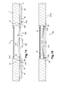
- FIG. 14 and 15 is shown a fifth embodiment of a system 440 equipping a facility 410 according to the invention.
- Some elements of the installation 410 and the system 440 are identical to the installation 10 and the system 40 of the first embodiment, described above, and have the same references.
- the system 440 comprises a telescopic bar 470, some of whose constituent elements have a similar operation, but a different structure, in comparison with the bar 370 of the fourth embodiment, described above, and have the same references increased by 100. parts 472, 480 and 490, groove 474, and stops 478 and 479.
- the main difference with the bar 370 is that the bar 470 is curved, with its three parts 472, 480 and 490 which are movable along a curved trajectory A470 of telescopic displacement.
- the curved bar 470 is less visible than a straight bar in the open position of the leaves 20 and 30, because part of the bar 470 is housed in the frame 4 of the window 3, on the "inside" side of the plane. P0.
- the actuators 50 and 60 are closer to the hinges, respectively 21 and 31, than in the previous embodiments, because of the curved shape of the bar 470. Thus, a potential contact between the bar 470 and the masonry is avoided.
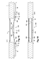
- FIG. 16 and 17 On the Figures 16 and 17 is shown a sixth embodiment of a system 540 equipping a facility 510 according to the invention.
- Some elements of the installation 510 and the system 540 are identical to the installation 10 and the system 40 of the first embodiment, described above, and have the same references.
- the system 540 comprises a telescopic bar 570, some of whose constituent elements have a similar operation, but a different structure, in comparison with the bar 370 of the fourth embodiment, described above, and have the same references increased by 200. Parts 572, 580 and 590, the axis A570, the groove 574, and the stops 578 and 579.
- the main difference with the bar 370 is that the bar 570 is shifted towards the frame 4 of the window 3, with the parts 580 and 590 which are curved, while the portion 572 extends straight along the axis A570 .
- the three parts 572, 580 and 590 are movable along the axis A570, which constitutes a telescopic displacement path. In comparison with the axis A370, this axis A570 does not intersect the axes of rotation of the output shafts of the actuators 50 and 60.
- the offset bar 580 is less visible than a straight bar in the open position wings 20 and 30.
- FIG. 18 and 19 is represented a seventh embodiment of a system 640 equipping an installation 610 according to the invention.
- Some components of the installation 610 and the system 640 are identical to the installation 10 and the system 40 of the first embodiment, described above, and have the same references.
- the system 640 comprises a telescopic bar 670 which is similar to the bar 70 of the first embodiment, described above, and whose constituent elements bear the same references increased by 600. These are the parts 680 and 690, the surfaces 681 and 691, as well as ends 682, 684, 692 and 694.
- the main difference with the bar 70 is that the bar 670 is flexible and non-rigid.
- the parts 680 and 690 are for example made of carbon fiber or fiberglass.
- the bar 670 is curved in the open position, as shown in FIG. figure 18 , and right in the closed position, as shown in figure 19 .
- Co-operating means 686 and 686 of the portions 680 and 690 are positioned at their respective ends 684 and 694.
- the portions 680 and 690 slide against each other at the surfaces 681 and 691.
- the parts 680 and 690 are movable along a path A670, which is a curved line in the open position and a straight line in the closed position.
- the trajectory A670 evolves during the opening and closing operations of the leaves 20 and 30.
- the technical features of the various embodiments may be, in whole or in part, combined with each other.
- the installation and the system according to the invention can be adapted to an application particularly in terms of cost, congestion and operational constraints.
- the motorized system can be mounted simply, conveniently and without damage to the masonry, in any suitable configuration, on any type of double leaf opening installation.
- the telescopic bars are presented as accessories easy to implement with the actuators, to form part of the motorized system.
Landscapes
- Power-Operated Mechanisms For Wings (AREA)
Applications Claiming Priority (1)
| Application Number | Priority Date | Filing Date | Title |
|---|---|---|---|
| FR1156808A FR2978478B1 (fr) | 2011-07-26 | 2011-07-26 | Systeme autonome d'ouverture et de fermeture de battants, et installation equipee d'un tel systeme |
Publications (3)
| Publication Number | Publication Date |
|---|---|
| EP2551435A2 true EP2551435A2 (de) | 2013-01-30 |
| EP2551435A3 EP2551435A3 (de) | 2013-03-13 |
| EP2551435B1 EP2551435B1 (de) | 2017-03-22 |
Family
ID=46545291
Family Applications (1)
| Application Number | Title | Priority Date | Filing Date |
|---|---|---|---|
| EP12178064.7A Not-in-force EP2551435B1 (de) | 2011-07-26 | 2012-07-26 | Autonomes Öffnungs- und Schließsystem für Klappflügel, und mit einem solchen System ausgestattete Anlage |
Country Status (2)
| Country | Link |
|---|---|
| EP (1) | EP2551435B1 (de) |
| FR (1) | FR2978478B1 (de) |
Cited By (3)
| Publication number | Priority date | Publication date | Assignee | Title |
|---|---|---|---|---|
| CN110284786A (zh) * | 2019-05-06 | 2019-09-27 | 上海澄东锁具有限公司 | 一种能够控制窗户开启大小的锁 |
| FR3091716A1 (fr) | 2019-01-15 | 2020-07-17 | Gerald LECLERCQ | Dispositif facilitant l’ouverture, la fermeture et le maintien en position ouverte de volets à un ou deux battants. |
| DE102023208713A1 (de) * | 2023-09-08 | 2025-03-13 | Geze Gmbh | Schließfolgeregelung, Schließersystem und zweiflügelige Tür |
Citations (1)
| Publication number | Priority date | Publication date | Assignee | Title |
|---|---|---|---|---|
| FR2638779A1 (fr) | 1988-11-10 | 1990-05-11 | Vernois Goulven | Dispositif pour la manoeuvre, simultanee ou non, manuelle ou motorisee, des deux volets d'une baie de batiment |
Family Cites Families (3)
| Publication number | Priority date | Publication date | Assignee | Title |
|---|---|---|---|---|
| FR2741651B1 (fr) * | 1995-11-23 | 1999-09-10 | Rohee Rene Denis Georges | Dispositif assurant l'arret automatique et la synchronisation de volets battants motorises a l'ouverture et a la fermeture |
| EP1340877B1 (de) * | 2002-03-01 | 2016-05-25 | GEZE GmbH | Türantrieb |
| US8111997B2 (en) * | 2008-06-30 | 2012-02-07 | The Chamberlain Group, Inc. | Multiple movable barrier operator system and method |
-
2011
- 2011-07-26 FR FR1156808A patent/FR2978478B1/fr active Active
-
2012
- 2012-07-26 EP EP12178064.7A patent/EP2551435B1/de not_active Not-in-force
Patent Citations (1)
| Publication number | Priority date | Publication date | Assignee | Title |
|---|---|---|---|---|
| FR2638779A1 (fr) | 1988-11-10 | 1990-05-11 | Vernois Goulven | Dispositif pour la manoeuvre, simultanee ou non, manuelle ou motorisee, des deux volets d'une baie de batiment |
Cited By (3)
| Publication number | Priority date | Publication date | Assignee | Title |
|---|---|---|---|---|
| FR3091716A1 (fr) | 2019-01-15 | 2020-07-17 | Gerald LECLERCQ | Dispositif facilitant l’ouverture, la fermeture et le maintien en position ouverte de volets à un ou deux battants. |
| CN110284786A (zh) * | 2019-05-06 | 2019-09-27 | 上海澄东锁具有限公司 | 一种能够控制窗户开启大小的锁 |
| DE102023208713A1 (de) * | 2023-09-08 | 2025-03-13 | Geze Gmbh | Schließfolgeregelung, Schließersystem und zweiflügelige Tür |
Also Published As
| Publication number | Publication date |
|---|---|
| EP2551435A3 (de) | 2013-03-13 |
| FR2978478A1 (fr) | 2013-02-01 |
| FR2978478B1 (fr) | 2014-05-16 |
| EP2551435B1 (de) | 2017-03-22 |
Similar Documents
| Publication | Publication Date | Title |
|---|---|---|
| EP3207190B1 (de) | Einheit zum abdecken und aufdecken einer oberfläche mit selbstangetriebenen verstellbaren lamellen | |
| EP3443177A1 (de) | Vorrichtung zum abdecken und freilegen einer oberfläche mit gekoppelten selbstfahrenden einstellbaren latten | |
| EP3325753B1 (de) | Vorrichtung zum aufwickeln einer abschirmung mit einer scharnierwandbefestigung | |
| EP3722547B1 (de) | Motorisierte antriebsvorrichtung, entsprechendes schiebefenster für ein gebäude und entsprechende haustechnikanlage | |
| EP2551435B1 (de) | Autonomes Öffnungs- und Schließsystem für Klappflügel, und mit einem solchen System ausgestattete Anlage | |
| EP3571368B1 (de) | Schiebefenster für ein gebäude, heimautomatisierungsanlage mit solch einem schiebefenster und verfahren zur steuerung des betriebs einer motorisierten antriebsvorrichtung für solch ein fenster | |
| WO2012052416A1 (fr) | Volet roulant pour ouvrant de batiment | |
| EP2551434B1 (de) | System und Verfahren zur Öffnung und Schließung von Klappflügeln, mit einem solchen System ausgestattete Anlage und Heimanlage, die mindestens zwei Anlagen umfasst | |
| EP2535497B1 (de) | Einrichtung zur wärmeisolierung und für den sonnenschutz | |
| WO2018046731A1 (fr) | Fenêtre coulissante pour un bâtiment et installation domotique comprenant une telle fenêtre coulissante | |
| EP3216963B1 (de) | Dreh-kippfenster für ein gebäude, und hausanlage, die ein solches dreh-kippfenster umfasst | |
| EP1674647A2 (de) | Antriebsvorrichtung für Schliesssystem wie Laden, Tor usw. | |
| EP2596195B1 (de) | Steuerungsvorrichtung für einen gebäudeabschluss und sein betriebsverfahren | |
| EP3190253B1 (de) | Dreh-kippfenster für ein gebäude, und hausanlage, die ein solches dreh-kippfenster umfasst | |
| EP3333349A1 (de) | Dreh-kippfenster für ein gebäude, hausanlage, die ein solches dreh-kippfenster umfasst, und betriebssteuerungsverfahren einer motorisierten antriebsvorrichtung für ein solches fenster | |
| EP3517721B1 (de) | Schiebefenster für ein gebäude, und heimtechnikanlage, die ein solches schiebefenster umfasst | |
| EP2652232A1 (de) | Rotationsmechanismus für rollladenlatten | |
| EP2236730A2 (de) | Rollo-Kombination, insbesondere für Bullauge eines Luftfahrzeugs, die Mittel zur Aufrechterhaltung der Spannung umfasst | |
| EP2305941A1 (de) | Vorrichtung zur Wärmedämmung von Tür- und Fensteröffnungen | |
| FR2958317A1 (fr) | Volet roulant | |
| EP2236729A2 (de) | Rollo-Kombination mit zwei Blenden insbesondere für Bullauge eines Luftfahrzeugs | |
| FR2963923A1 (fr) | Dispositif pour la fermeture d'une baie, notamment pour un bateau de plaisance | |
| FR2941479A1 (fr) | Volet roulant mixte | |
| FR3055648A1 (fr) | Desaccouplement du bras de commande d'un volet battant. | |
| FR3071863A1 (fr) | Porte motorisee |
Legal Events
| Date | Code | Title | Description |
|---|---|---|---|
| PUAI | Public reference made under article 153(3) epc to a published international application that has entered the european phase |
Free format text: ORIGINAL CODE: 0009012 |
|
| AK | Designated contracting states |
Kind code of ref document: A2 Designated state(s): AL AT BE BG CH CY CZ DE DK EE ES FI FR GB GR HR HU IE IS IT LI LT LU LV MC MK MT NL NO PL PT RO RS SE SI SK SM TR |
|
| AX | Request for extension of the european patent |
Extension state: BA ME |
|
| PUAL | Search report despatched |
Free format text: ORIGINAL CODE: 0009013 |
|
| AK | Designated contracting states |
Kind code of ref document: A3 Designated state(s): AL AT BE BG CH CY CZ DE DK EE ES FI FR GB GR HR HU IE IS IT LI LT LU LV MC MK MT NL NO PL PT RO RS SE SI SK SM TR |
|
| AX | Request for extension of the european patent |
Extension state: BA ME |
|
| RIC1 | Information provided on ipc code assigned before grant |
Ipc: E05F 5/12 20060101ALN20130201BHEP Ipc: E05F 15/12 20060101ALI20130201BHEP Ipc: E05F 17/00 20060101AFI20130201BHEP |
|
| 17P | Request for examination filed |
Effective date: 20130904 |
|
| RBV | Designated contracting states (corrected) |
Designated state(s): AL AT BE BG CH CY CZ DE DK EE ES FI FR GB GR HR HU IE IS IT LI LT LU LV MC MK MT NL NO PL PT RO RS SE SI SK SM TR |
|
| 17Q | First examination report despatched |
Effective date: 20160111 |
|
| RIC1 | Information provided on ipc code assigned before grant |
Ipc: E05F 15/611 20150101ALI20160819BHEP Ipc: E05F 17/00 20060101AFI20160819BHEP Ipc: E05F 5/12 20060101ALN20160819BHEP |
|
| GRAP | Despatch of communication of intention to grant a patent |
Free format text: ORIGINAL CODE: EPIDOSNIGR1 |
|
| INTG | Intention to grant announced |
Effective date: 20161004 |
|
| GRAJ | Information related to disapproval of communication of intention to grant by the applicant or resumption of examination proceedings by the epo deleted |
Free format text: ORIGINAL CODE: EPIDOSDIGR1 |
|
| GRAR | Information related to intention to grant a patent recorded |
Free format text: ORIGINAL CODE: EPIDOSNIGR71 |
|
| GRAS | Grant fee paid |
Free format text: ORIGINAL CODE: EPIDOSNIGR3 |
|
| GRAA | (expected) grant |
Free format text: ORIGINAL CODE: 0009210 |
|
| INTC | Intention to grant announced (deleted) | ||
| RIC1 | Information provided on ipc code assigned before grant |
Ipc: E05F 15/611 20150101ALI20170209BHEP Ipc: E05F 17/00 20060101AFI20170209BHEP Ipc: E05F 5/12 20060101ALN20170209BHEP |
|
| AK | Designated contracting states |
Kind code of ref document: B1 Designated state(s): AL AT BE BG CH CY CZ DE DK EE ES FI FR GB GR HR HU IE IS IT LI LT LU LV MC MK MT NL NO PL PT RO RS SE SI SK SM TR |
|
| INTG | Intention to grant announced |
Effective date: 20170210 |
|
| REG | Reference to a national code |
Ref country code: GB Ref legal event code: FG4D Free format text: NOT ENGLISH |
|
| REG | Reference to a national code |
Ref country code: CH Ref legal event code: EP |
|
| REG | Reference to a national code |
Ref country code: AT Ref legal event code: REF Ref document number: 877985 Country of ref document: AT Kind code of ref document: T Effective date: 20170415 |
|
| REG | Reference to a national code |
Ref country code: IE Ref legal event code: FG4D Free format text: LANGUAGE OF EP DOCUMENT: FRENCH |
|
| REG | Reference to a national code |
Ref country code: DE Ref legal event code: R096 Ref document number: 602012030060 Country of ref document: DE |
|
| REG | Reference to a national code |
Ref country code: NL Ref legal event code: MP Effective date: 20170322 Ref country code: FR Ref legal event code: PLFP Year of fee payment: 6 |
|
| PG25 | Lapsed in a contracting state [announced via postgrant information from national office to epo] |
Ref country code: HR Free format text: LAPSE BECAUSE OF FAILURE TO SUBMIT A TRANSLATION OF THE DESCRIPTION OR TO PAY THE FEE WITHIN THE PRESCRIBED TIME-LIMIT Effective date: 20170322 Ref country code: LT Free format text: LAPSE BECAUSE OF FAILURE TO SUBMIT A TRANSLATION OF THE DESCRIPTION OR TO PAY THE FEE WITHIN THE PRESCRIBED TIME-LIMIT Effective date: 20170322 Ref country code: GR Free format text: LAPSE BECAUSE OF FAILURE TO SUBMIT A TRANSLATION OF THE DESCRIPTION OR TO PAY THE FEE WITHIN THE PRESCRIBED TIME-LIMIT Effective date: 20170623 Ref country code: FI Free format text: LAPSE BECAUSE OF FAILURE TO SUBMIT A TRANSLATION OF THE DESCRIPTION OR TO PAY THE FEE WITHIN THE PRESCRIBED TIME-LIMIT Effective date: 20170322 Ref country code: NO Free format text: LAPSE BECAUSE OF FAILURE TO SUBMIT A TRANSLATION OF THE DESCRIPTION OR TO PAY THE FEE WITHIN THE PRESCRIBED TIME-LIMIT Effective date: 20170622 |
|
| REG | Reference to a national code |
Ref country code: LT Ref legal event code: MG4D |
|
| REG | Reference to a national code |
Ref country code: AT Ref legal event code: MK05 Ref document number: 877985 Country of ref document: AT Kind code of ref document: T Effective date: 20170322 |
|
| PG25 | Lapsed in a contracting state [announced via postgrant information from national office to epo] |
Ref country code: BG Free format text: LAPSE BECAUSE OF FAILURE TO SUBMIT A TRANSLATION OF THE DESCRIPTION OR TO PAY THE FEE WITHIN THE PRESCRIBED TIME-LIMIT Effective date: 20170622 Ref country code: SE Free format text: LAPSE BECAUSE OF FAILURE TO SUBMIT A TRANSLATION OF THE DESCRIPTION OR TO PAY THE FEE WITHIN THE PRESCRIBED TIME-LIMIT Effective date: 20170322 Ref country code: LV Free format text: LAPSE BECAUSE OF FAILURE TO SUBMIT A TRANSLATION OF THE DESCRIPTION OR TO PAY THE FEE WITHIN THE PRESCRIBED TIME-LIMIT Effective date: 20170322 Ref country code: RS Free format text: LAPSE BECAUSE OF FAILURE TO SUBMIT A TRANSLATION OF THE DESCRIPTION OR TO PAY THE FEE WITHIN THE PRESCRIBED TIME-LIMIT Effective date: 20170322 |
|
| PG25 | Lapsed in a contracting state [announced via postgrant information from national office to epo] |
Ref country code: NL Free format text: LAPSE BECAUSE OF FAILURE TO SUBMIT A TRANSLATION OF THE DESCRIPTION OR TO PAY THE FEE WITHIN THE PRESCRIBED TIME-LIMIT Effective date: 20170322 |
|
| PG25 | Lapsed in a contracting state [announced via postgrant information from national office to epo] |
Ref country code: RO Free format text: LAPSE BECAUSE OF FAILURE TO SUBMIT A TRANSLATION OF THE DESCRIPTION OR TO PAY THE FEE WITHIN THE PRESCRIBED TIME-LIMIT Effective date: 20170322 Ref country code: AT Free format text: LAPSE BECAUSE OF FAILURE TO SUBMIT A TRANSLATION OF THE DESCRIPTION OR TO PAY THE FEE WITHIN THE PRESCRIBED TIME-LIMIT Effective date: 20170322 Ref country code: SK Free format text: LAPSE BECAUSE OF FAILURE TO SUBMIT A TRANSLATION OF THE DESCRIPTION OR TO PAY THE FEE WITHIN THE PRESCRIBED TIME-LIMIT Effective date: 20170322 Ref country code: EE Free format text: LAPSE BECAUSE OF FAILURE TO SUBMIT A TRANSLATION OF THE DESCRIPTION OR TO PAY THE FEE WITHIN THE PRESCRIBED TIME-LIMIT Effective date: 20170322 Ref country code: IT Free format text: LAPSE BECAUSE OF FAILURE TO SUBMIT A TRANSLATION OF THE DESCRIPTION OR TO PAY THE FEE WITHIN THE PRESCRIBED TIME-LIMIT Effective date: 20170322 Ref country code: ES Free format text: LAPSE BECAUSE OF FAILURE TO SUBMIT A TRANSLATION OF THE DESCRIPTION OR TO PAY THE FEE WITHIN THE PRESCRIBED TIME-LIMIT Effective date: 20170322 Ref country code: CZ Free format text: LAPSE BECAUSE OF FAILURE TO SUBMIT A TRANSLATION OF THE DESCRIPTION OR TO PAY THE FEE WITHIN THE PRESCRIBED TIME-LIMIT Effective date: 20170322 |
|
| PG25 | Lapsed in a contracting state [announced via postgrant information from national office to epo] |
Ref country code: PL Free format text: LAPSE BECAUSE OF FAILURE TO SUBMIT A TRANSLATION OF THE DESCRIPTION OR TO PAY THE FEE WITHIN THE PRESCRIBED TIME-LIMIT Effective date: 20170322 Ref country code: SM Free format text: LAPSE BECAUSE OF FAILURE TO SUBMIT A TRANSLATION OF THE DESCRIPTION OR TO PAY THE FEE WITHIN THE PRESCRIBED TIME-LIMIT Effective date: 20170322 Ref country code: IS Free format text: LAPSE BECAUSE OF FAILURE TO SUBMIT A TRANSLATION OF THE DESCRIPTION OR TO PAY THE FEE WITHIN THE PRESCRIBED TIME-LIMIT Effective date: 20170722 Ref country code: PT Free format text: LAPSE BECAUSE OF FAILURE TO SUBMIT A TRANSLATION OF THE DESCRIPTION OR TO PAY THE FEE WITHIN THE PRESCRIBED TIME-LIMIT Effective date: 20170724 |
|
| REG | Reference to a national code |
Ref country code: DE Ref legal event code: R097 Ref document number: 602012030060 Country of ref document: DE |
|
| PLBE | No opposition filed within time limit |
Free format text: ORIGINAL CODE: 0009261 |
|
| STAA | Information on the status of an ep patent application or granted ep patent |
Free format text: STATUS: NO OPPOSITION FILED WITHIN TIME LIMIT |
|
| PG25 | Lapsed in a contracting state [announced via postgrant information from national office to epo] |
Ref country code: DK Free format text: LAPSE BECAUSE OF FAILURE TO SUBMIT A TRANSLATION OF THE DESCRIPTION OR TO PAY THE FEE WITHIN THE PRESCRIBED TIME-LIMIT Effective date: 20170322 |
|
| 26N | No opposition filed |
Effective date: 20180102 |
|
| PG25 | Lapsed in a contracting state [announced via postgrant information from national office to epo] |
Ref country code: SI Free format text: LAPSE BECAUSE OF FAILURE TO SUBMIT A TRANSLATION OF THE DESCRIPTION OR TO PAY THE FEE WITHIN THE PRESCRIBED TIME-LIMIT Effective date: 20170322 |
|
| REG | Reference to a national code |
Ref country code: CH Ref legal event code: PL |
|
| GBPC | Gb: european patent ceased through non-payment of renewal fee |
Effective date: 20170726 |
|
| REG | Reference to a national code |
Ref country code: IE Ref legal event code: MM4A |
|
| PG25 | Lapsed in a contracting state [announced via postgrant information from national office to epo] |
Ref country code: LI Free format text: LAPSE BECAUSE OF NON-PAYMENT OF DUE FEES Effective date: 20170731 Ref country code: IE Free format text: LAPSE BECAUSE OF NON-PAYMENT OF DUE FEES Effective date: 20170726 Ref country code: CH Free format text: LAPSE BECAUSE OF NON-PAYMENT OF DUE FEES Effective date: 20170731 Ref country code: GB Free format text: LAPSE BECAUSE OF NON-PAYMENT OF DUE FEES Effective date: 20170726 |
|
| REG | Reference to a national code |
Ref country code: BE Ref legal event code: MM Effective date: 20170731 |
|
| PG25 | Lapsed in a contracting state [announced via postgrant information from national office to epo] |
Ref country code: LU Free format text: LAPSE BECAUSE OF NON-PAYMENT OF DUE FEES Effective date: 20170726 |
|
| REG | Reference to a national code |
Ref country code: FR Ref legal event code: PLFP Year of fee payment: 7 |
|
| PG25 | Lapsed in a contracting state [announced via postgrant information from national office to epo] |
Ref country code: BE Free format text: LAPSE BECAUSE OF NON-PAYMENT OF DUE FEES Effective date: 20170731 |
|
| PG25 | Lapsed in a contracting state [announced via postgrant information from national office to epo] |
Ref country code: MT Free format text: LAPSE BECAUSE OF FAILURE TO SUBMIT A TRANSLATION OF THE DESCRIPTION OR TO PAY THE FEE WITHIN THE PRESCRIBED TIME-LIMIT Effective date: 20170322 |
|
| PG25 | Lapsed in a contracting state [announced via postgrant information from national office to epo] |
Ref country code: HU Free format text: LAPSE BECAUSE OF FAILURE TO SUBMIT A TRANSLATION OF THE DESCRIPTION OR TO PAY THE FEE WITHIN THE PRESCRIBED TIME-LIMIT; INVALID AB INITIO Effective date: 20120726 Ref country code: MC Free format text: LAPSE BECAUSE OF FAILURE TO SUBMIT A TRANSLATION OF THE DESCRIPTION OR TO PAY THE FEE WITHIN THE PRESCRIBED TIME-LIMIT Effective date: 20170322 |
|
| PG25 | Lapsed in a contracting state [announced via postgrant information from national office to epo] |
Ref country code: CY Free format text: LAPSE BECAUSE OF NON-PAYMENT OF DUE FEES Effective date: 20170322 |
|
| PG25 | Lapsed in a contracting state [announced via postgrant information from national office to epo] |
Ref country code: MK Free format text: LAPSE BECAUSE OF FAILURE TO SUBMIT A TRANSLATION OF THE DESCRIPTION OR TO PAY THE FEE WITHIN THE PRESCRIBED TIME-LIMIT Effective date: 20170322 |
|
| PG25 | Lapsed in a contracting state [announced via postgrant information from national office to epo] |
Ref country code: TR Free format text: LAPSE BECAUSE OF FAILURE TO SUBMIT A TRANSLATION OF THE DESCRIPTION OR TO PAY THE FEE WITHIN THE PRESCRIBED TIME-LIMIT Effective date: 20170322 |
|
| PG25 | Lapsed in a contracting state [announced via postgrant information from national office to epo] |
Ref country code: AL Free format text: LAPSE BECAUSE OF FAILURE TO SUBMIT A TRANSLATION OF THE DESCRIPTION OR TO PAY THE FEE WITHIN THE PRESCRIBED TIME-LIMIT Effective date: 20170322 |
|
| REG | Reference to a national code |
Ref country code: DE Ref legal event code: R082 Ref document number: 602012030060 Country of ref document: DE Representative=s name: LAVOIX MUNICH, DE Ref country code: DE Ref legal event code: R081 Ref document number: 602012030060 Country of ref document: DE Owner name: SOMFY ACTIVITIES SA, FR Free format text: FORMER OWNER: SOMFY SAS, CLUSES, FR Ref country code: DE Ref legal event code: R081 Ref document number: 602012030060 Country of ref document: DE Owner name: SOMFY ACTIVITES SA, FR Free format text: FORMER OWNER: SOMFY SAS, CLUSES, FR |
|
| REG | Reference to a national code |
Ref country code: DE Ref legal event code: R082 Ref document number: 602012030060 Country of ref document: DE Representative=s name: LAVOIX MUNICH, DE Ref country code: DE Ref legal event code: R081 Ref document number: 602012030060 Country of ref document: DE Owner name: SOMFY ACTIVITES SA, FR Free format text: FORMER OWNER: SOMFY ACTIVITIES SA, CLUSES, FR |
|
| PGFP | Annual fee paid to national office [announced via postgrant information from national office to epo] |
Ref country code: FR Payment date: 20210721 Year of fee payment: 10 |
|
| PGFP | Annual fee paid to national office [announced via postgrant information from national office to epo] |
Ref country code: DE Payment date: 20220624 Year of fee payment: 11 |
|
| PG25 | Lapsed in a contracting state [announced via postgrant information from national office to epo] |
Ref country code: FR Free format text: LAPSE BECAUSE OF NON-PAYMENT OF DUE FEES Effective date: 20220731 |
|
| REG | Reference to a national code |
Ref country code: DE Ref legal event code: R119 Ref document number: 602012030060 Country of ref document: DE |
|
| PG25 | Lapsed in a contracting state [announced via postgrant information from national office to epo] |
Ref country code: DE Free format text: LAPSE BECAUSE OF NON-PAYMENT OF DUE FEES Effective date: 20240201 |