EP2546494B1 - Assembly method for a gas turbine fan drive gear system - Google Patents
Assembly method for a gas turbine fan drive gear system Download PDFInfo
- Publication number
- EP2546494B1 EP2546494B1 EP12180834.9A EP12180834A EP2546494B1 EP 2546494 B1 EP2546494 B1 EP 2546494B1 EP 12180834 A EP12180834 A EP 12180834A EP 2546494 B1 EP2546494 B1 EP 2546494B1
- Authority
- EP
- European Patent Office
- Prior art keywords
- carrier
- mounts
- intermediate gears
- walls
- baffles
- Prior art date
- Legal status (The legal status is an assumption and is not a legal conclusion. Google has not performed a legal analysis and makes no representation as to the accuracy of the status listed.)
- Active
Links
Images


Classifications
-
- F—MECHANICAL ENGINEERING; LIGHTING; HEATING; WEAPONS; BLASTING
- F16—ENGINEERING ELEMENTS AND UNITS; GENERAL MEASURES FOR PRODUCING AND MAINTAINING EFFECTIVE FUNCTIONING OF MACHINES OR INSTALLATIONS; THERMAL INSULATION IN GENERAL
- F16H—GEARING
- F16H57/00—General details of gearing
- F16H57/04—Features relating to lubrication or cooling or heating
- F16H57/042—Guidance of lubricant
- F16H57/0427—Guidance of lubricant on rotary parts, e.g. using baffles for collecting lubricant by centrifugal force
-
- F—MECHANICAL ENGINEERING; LIGHTING; HEATING; WEAPONS; BLASTING
- F01—MACHINES OR ENGINES IN GENERAL; ENGINE PLANTS IN GENERAL; STEAM ENGINES
- F01D—NON-POSITIVE DISPLACEMENT MACHINES OR ENGINES, e.g. STEAM TURBINES
- F01D25/00—Component parts, details, or accessories, not provided for in, or of interest apart from, other groups
- F01D25/18—Lubricating arrangements
-
- F—MECHANICAL ENGINEERING; LIGHTING; HEATING; WEAPONS; BLASTING
- F02—COMBUSTION ENGINES; HOT-GAS OR COMBUSTION-PRODUCT ENGINE PLANTS
- F02C—GAS-TURBINE PLANTS; AIR INTAKES FOR JET-PROPULSION PLANTS; CONTROLLING FUEL SUPPLY IN AIR-BREATHING JET-PROPULSION PLANTS
- F02C3/00—Gas-turbine plants characterised by the use of combustion products as the working fluid
- F02C3/04—Gas-turbine plants characterised by the use of combustion products as the working fluid having a turbine driving a compressor
-
- F—MECHANICAL ENGINEERING; LIGHTING; HEATING; WEAPONS; BLASTING
- F02—COMBUSTION ENGINES; HOT-GAS OR COMBUSTION-PRODUCT ENGINE PLANTS
- F02C—GAS-TURBINE PLANTS; AIR INTAKES FOR JET-PROPULSION PLANTS; CONTROLLING FUEL SUPPLY IN AIR-BREATHING JET-PROPULSION PLANTS
- F02C7/00—Features, components parts, details or accessories, not provided for in, or of interest apart form groups F02C1/00 - F02C6/00; Air intakes for jet-propulsion plants
- F02C7/36—Power transmission arrangements between the different shafts of the gas turbine plant, or between the gas-turbine plant and the power user
-
- F—MECHANICAL ENGINEERING; LIGHTING; HEATING; WEAPONS; BLASTING
- F16—ENGINEERING ELEMENTS AND UNITS; GENERAL MEASURES FOR PRODUCING AND MAINTAINING EFFECTIVE FUNCTIONING OF MACHINES OR INSTALLATIONS; THERMAL INSULATION IN GENERAL
- F16H—GEARING
- F16H57/00—General details of gearing
- F16H57/04—Features relating to lubrication or cooling or heating
- F16H57/042—Guidance of lubricant
- F16H57/0421—Guidance of lubricant on or within the casing, e.g. shields or baffles for collecting lubricant, tubes, pipes, grooves, channels or the like
- F16H57/0423—Lubricant guiding means mounted or supported on the casing, e.g. shields or baffles for collecting lubricant, tubes or pipes
-
- F—MECHANICAL ENGINEERING; LIGHTING; HEATING; WEAPONS; BLASTING
- F16—ENGINEERING ELEMENTS AND UNITS; GENERAL MEASURES FOR PRODUCING AND MAINTAINING EFFECTIVE FUNCTIONING OF MACHINES OR INSTALLATIONS; THERMAL INSULATION IN GENERAL
- F16H—GEARING
- F16H57/00—General details of gearing
- F16H57/04—Features relating to lubrication or cooling or heating
- F16H57/0458—Oil-mist or spray lubrication; Means to reduce foam formation
- F16H57/046—Oil-mist or spray lubrication
-
- F—MECHANICAL ENGINEERING; LIGHTING; HEATING; WEAPONS; BLASTING
- F16—ENGINEERING ELEMENTS AND UNITS; GENERAL MEASURES FOR PRODUCING AND MAINTAINING EFFECTIVE FUNCTIONING OF MACHINES OR INSTALLATIONS; THERMAL INSULATION IN GENERAL
- F16H—GEARING
- F16H57/00—General details of gearing
- F16H57/04—Features relating to lubrication or cooling or heating
- F16H57/0467—Elements of gearings to be lubricated, cooled or heated
- F16H57/0479—Gears or bearings on planet carriers
-
- F—MECHANICAL ENGINEERING; LIGHTING; HEATING; WEAPONS; BLASTING
- F16—ENGINEERING ELEMENTS AND UNITS; GENERAL MEASURES FOR PRODUCING AND MAINTAINING EFFECTIVE FUNCTIONING OF MACHINES OR INSTALLATIONS; THERMAL INSULATION IN GENERAL
- F16H—GEARING
- F16H57/00—General details of gearing
- F16H57/04—Features relating to lubrication or cooling or heating
- F16H57/048—Type of gearings to be lubricated, cooled or heated
- F16H57/0482—Gearings with gears having orbital motion
-
- F—MECHANICAL ENGINEERING; LIGHTING; HEATING; WEAPONS; BLASTING
- F05—INDEXING SCHEMES RELATING TO ENGINES OR PUMPS IN VARIOUS SUBCLASSES OF CLASSES F01-F04
- F05D—INDEXING SCHEME FOR ASPECTS RELATING TO NON-POSITIVE-DISPLACEMENT MACHINES OR ENGINES, GAS-TURBINES OR JET-PROPULSION PLANTS
- F05D2230/00—Manufacture
- F05D2230/60—Assembly methods
-
- F—MECHANICAL ENGINEERING; LIGHTING; HEATING; WEAPONS; BLASTING
- F05—INDEXING SCHEMES RELATING TO ENGINES OR PUMPS IN VARIOUS SUBCLASSES OF CLASSES F01-F04
- F05D—INDEXING SCHEME FOR ASPECTS RELATING TO NON-POSITIVE-DISPLACEMENT MACHINES OR ENGINES, GAS-TURBINES OR JET-PROPULSION PLANTS
- F05D2260/00—Function
- F05D2260/40—Transmission of power
- F05D2260/403—Transmission of power through the shape of the drive components
- F05D2260/4031—Transmission of power through the shape of the drive components as in toothed gearing
- F05D2260/40311—Transmission of power through the shape of the drive components as in toothed gearing of the epicyclical, planetary or differential type
-
- F—MECHANICAL ENGINEERING; LIGHTING; HEATING; WEAPONS; BLASTING
- F05—INDEXING SCHEMES RELATING TO ENGINES OR PUMPS IN VARIOUS SUBCLASSES OF CLASSES F01-F04
- F05D—INDEXING SCHEME FOR ASPECTS RELATING TO NON-POSITIVE-DISPLACEMENT MACHINES OR ENGINES, GAS-TURBINES OR JET-PROPULSION PLANTS
- F05D2260/00—Function
- F05D2260/98—Lubrication
-
- F—MECHANICAL ENGINEERING; LIGHTING; HEATING; WEAPONS; BLASTING
- F16—ENGINEERING ELEMENTS AND UNITS; GENERAL MEASURES FOR PRODUCING AND MAINTAINING EFFECTIVE FUNCTIONING OF MACHINES OR INSTALLATIONS; THERMAL INSULATION IN GENERAL
- F16H—GEARING
- F16H57/00—General details of gearing
- F16H57/04—Features relating to lubrication or cooling or heating
- F16H57/048—Type of gearings to be lubricated, cooled or heated
- F16H57/0482—Gearings with gears having orbital motion
- F16H57/0486—Gearings with gears having orbital motion with fixed gear ratio
-
- F—MECHANICAL ENGINEERING; LIGHTING; HEATING; WEAPONS; BLASTING
- F16—ENGINEERING ELEMENTS AND UNITS; GENERAL MEASURES FOR PRODUCING AND MAINTAINING EFFECTIVE FUNCTIONING OF MACHINES OR INSTALLATIONS; THERMAL INSULATION IN GENERAL
- F16H—GEARING
- F16H57/00—General details of gearing
- F16H57/08—General details of gearing of gearings with members having orbital motion
- F16H57/082—Planet carriers
-
- Y—GENERAL TAGGING OF NEW TECHNOLOGICAL DEVELOPMENTS; GENERAL TAGGING OF CROSS-SECTIONAL TECHNOLOGIES SPANNING OVER SEVERAL SECTIONS OF THE IPC; TECHNICAL SUBJECTS COVERED BY FORMER USPC CROSS-REFERENCE ART COLLECTIONS [XRACs] AND DIGESTS
- Y10—TECHNICAL SUBJECTS COVERED BY FORMER USPC
- Y10T—TECHNICAL SUBJECTS COVERED BY FORMER US CLASSIFICATION
- Y10T29/00—Metal working
- Y10T29/49—Method of mechanical manufacture
- Y10T29/49316—Impeller making
- Y10T29/4932—Turbomachine making
- Y10T29/49323—Assembling fluid flow directing devices, e.g., stators, diaphragms, nozzles
-
- Y—GENERAL TAGGING OF NEW TECHNOLOGICAL DEVELOPMENTS; GENERAL TAGGING OF CROSS-SECTIONAL TECHNOLOGIES SPANNING OVER SEVERAL SECTIONS OF THE IPC; TECHNICAL SUBJECTS COVERED BY FORMER USPC CROSS-REFERENCE ART COLLECTIONS [XRACs] AND DIGESTS
- Y10—TECHNICAL SUBJECTS COVERED BY FORMER USPC
- Y10T—TECHNICAL SUBJECTS COVERED BY FORMER US CLASSIFICATION
- Y10T29/00—Metal working
- Y10T29/49—Method of mechanical manufacture
- Y10T29/49462—Gear making
- Y10T29/49464—Assembling of gear into force transmitting device
Definitions
- This invention relates to an oil baffle arrangement for use in an epicyclic gear train employed to drive a turbo fan.
- Gas turbine engines typically employ an epicyclic gear train connected to a turbine section of the engine, which is used to drive the turbo fan.
- a sun gear receives rotational input from a turbine shaft through a compressor shaft.
- a carrier supports intermediate gears that surround and mesh with the sun gear.
- a ring gear surrounds and meshes with the intermediate gears.
- the intermediate gears are referred to as "star” gears and the ring gear is coupled to an output shaft that supports the turbo fan.
- the intermediate gears are referred to as "planetary” gears and the carrier is coupled to the output shaft that supports the turbo fan.
- the epicyclic gear train gears must receive adequate lubrication during operation of the turbine engine.
- the carrier includes oil spray bars arranged between the intermediate gears and the sun gear to spray oil directly on those gears.
- Separate oil baffles which may be integral with or separate from the carrier, are arranged between the intermediate gears to collect the sprayed oil and retain it in the area of the intermediate gears for prolonged lubrication before the oil is collected in a lubricant gutter associated with the ring gear.
- Prior art carrier arrangements (such as those disclosed in EP 1783344 , US 5472383 and US 6223616 ) have required multiple components and complicated assembly in order to accommodate the oil baffles. For example, one or both of the side walls of the carrier must be assembled around the intermediate gears resulting in a multi-piece carrier. Furthermore, separate oil spray bars and oil baffles complicate assembly and increase cost. What is needed is a simplified oil baffle and spray bar arrangement that enables a simpler and less expensive carrier design.
- a turbine engine disclosed herein includes a epicyclic gear train that drives a turbo fan.
- a carrier provides a unitary structure having spaced apart walls interconnected by circumferentially spaced mounts providing circumferentially spaced apertures at an outer circumference of the carrier.
- the carrier supports intermediate gears that surround and mesh with a centrally located sun gear.
- the intermediate gears extend through the apertures to mesh with a ring gear that surrounds the carrier.
- Baffles are arranged between the side walls adjacent to the mounts. Fasteners secure the baffles, which can be a different material than the carrier, to the carrier.
- the baffles include a lubrication passage that distributes oil to various parts of the epicyclic gear train.
- the invention provides a method of assembling an epicyclic gear train employable to drive a turbo fan of a gas turbine engine, the method comprising the steps of: providing a carrier that includes spaced apart walls and circumferentially spaced mounts interconnecting the walls in a one-piece unitary structure, spaced apart apertures provided between the mounts at an outer circumference of the carrier, gear pockets provided between the walls and mounts extending to the apertures, and a central opening in at least one of the walls; inserting intermediate gears through the central opening and moving the intermediate gears radially outwardly into the gear pockets so that they extend through the apertures and are in abutment with the mounts; inserting oil baffles into the carrier so that they are arranged between the side walls adjacent to the mounts and securing the oil baffles to the carrier near the intermediate gears; repositioning the intermediate gears by moving the intermediate gears radially inwardly into their operational positions in the gear pockets; inserting a sun gear through the central opening to intermesh with the intermediate gear
- FIG. 1 A portion of a gas turbine engine 10 is shown schematically in Figure 1 .
- the turbine engine 10 includes a fixed housing 12 that is constructed from numerous pieces secured to one another.
- a compressor section 14 having compressor hubs 16 with blades are driven by a turbine shaft (not shown) about an axis A.
- a turbo fan 18 is supported on a turbo fan shaft 20 that is driven by a compressor shaft 24, which supports the compressor hubs 16, through an epicyclic gear train 22.
- the epicyclic gear train 22 is a star gear train.
- the claimed invention also applies to other epicyclic gear trains such as a planetary arrangement.
- the epicyclic gear train 22 includes a sun gear 28 that is connected to the compressor shaft 24, which provides rotational input, by a splined connection 30.
- a carrier 34 is fixed to the housing 12 by a torque frame 36.
- the carrier 34 supports intermediate gears (which are star gears 32 in the arrangement shown) that are coupled to the sun gear 28 by meshed interfaces 26 between the teeth of the sun and star gears 28, 32.
- a ring gear 38 surrounds the carrier 34 and is coupled to the star gears 32 by meshed interfaces 44.
- the ring gear 38 which provides rotational output, is secured to the turbo fan shaft 20 by connection 42.
- the torque frame 36 grounds the carrier 34 to the housing 12 in a known manner.
- mounts 54 have apertures 56 receiving fingers of the torque frame 36, as shown in Figures 2 and 3 .
- Pins 48 that extend through spherical bearings 46 and bushings 52 secure the fingers to the carrier 34.
- Fasteners 50 retain the pins 48 to the carrier 34.
- the carrier 34 is a unitary structure manufactured from one piece for improved structural rigidity and ease of assembly.
- the carrier 34 includes spaced apart side walls 60 that are interconnected by the mounts 54, which are generally wedge-shaped members, as best shown in Figure 3 .
- the mounts 54 and side walls 60 are unitary with one another.
- the mounts 54 have opposing curved surfaces 58 that are in close proximity to the star gears 32 and generally follow the curvature of the teeth of the star gears 32 so that any oil on the curved surfaces 58 will likely find its way to the star gears 32 for additional lubrication.
- the mounts 54 are circumferentially spaced about the carrier 34 to provide apertures 98 through which the star gears 32 extend to engage the ring gear 38.
- the side walls 60 include holes 62 for receiving a journal bearing 64 that supports each of the star gears 32.
- Each journal bearing 64 is retained within the carrier 34 by retainers 66 fastened to the side walls 60.
- Oil baffles 68 are arranged between the side walls 60 near each of the mounts 54, best shown in Figure 2 .
- the baffles 68 include ends 72 that abut the mounts 54, in the example shown.
- the baffles 68 also include opposing curved surfaces 70 arranged in close proximity to the star gears 28.
- the curved surfaces 58, 70 are contiguous with and adjoin one another, in the example shown, and provide gear pockets 102 that receive the star gears 32.
- a gear pocket 104, which receives the sun gear 28, is also provided between a surface 73 on each of the baffles 68 opposite the ends 72.
- one of the side walls 60 includes holes 74 that receive fasteners 76 which secure each of the baffles 68 to the carrier 34.
- the baffles 68 include a lubrication passage provided by a primary passage 86 that fluidly communicates with a lubricant distributor 78.
- the lubricant distributor 78 is fed oil from a lubricant supply 96.
- the baffles 68 include openings 82 that receive a tube 80 extending through a hole 83 in the side wall 60. Seals 84 seal the tube 80 to the opening 82 and lubricant distributor 78.
- Other tubes 92 having seals 84 are used to provide oil to an external spray bar 94 through another lubrication passage (spray bar passage 93 that extends through one of the baffles 68).
- the external spray bar 94 is secured to the carrier 34 and sprays oil in the vicinity of the sun gear 28 near the splined connection 30 (shown in Figures 2 and 5 ).
- the primary passage 86 is in communication with first and second passages 88, 90 that spray oil on the teeth of the sun and star gears 28, 32.
- first and second passages 88, 90 are arranged ninety degrees from one another.
- baffles 68 With the oil baffles 68, lubricant distribution is integrated into the baffle so that separate components are eliminated.
- the baffles 68 can be constructed from a different, lighter weight material than the carrier 34.
- the example carrier 34 is constructed from one piece, which improves the structural integrity of the carrier.
- a central opening 100 is machined in at least one of the side walls 60 and provides the gear pocket 104.
- Gear pockets 102 are machined between the side walls 60 and mounts 54 for each of the star gears 32 and form apertures 98 at an outer circumference of the carrier 34.
- the star gears 32 are inserted into the central opening 100 and moved radially outwardly so that they extend through the apertures 98 and are preferably in abutment with the mounts 54 (position indicated by dashed lines in Figure 3 ). In this position, there is an adequate gap, t, between the teeth of adjacent star gears 32 to accommodate a width, w, of the end 72 of the baffles 68.
- the star gears 32 can be repositioned, as shown by the solid lines, and the sun gear 28 can be inserted into the central opening 100 so that it meshes with the star gears 32.
- the baffles 68 are secured to the carrier 34 using fasteners 76.
- the tubes 80, 92 can be inserted and the rest of the lubricant distribution system can be connected.
Description
- This invention relates to an oil baffle arrangement for use in an epicyclic gear train employed to drive a turbo fan.
- Gas turbine engines typically employ an epicyclic gear train connected to a turbine section of the engine, which is used to drive the turbo fan. In a typical epicyclic gear train, a sun gear receives rotational input from a turbine shaft through a compressor shaft. A carrier supports intermediate gears that surround and mesh with the sun gear. A ring gear surrounds and meshes with the intermediate gears. In arrangements in which the carrier is fixed against rotation, the intermediate gears are referred to as "star" gears and the ring gear is coupled to an output shaft that supports the turbo fan. In arrangements in which the ring gear is fixed against rotation, the intermediate gears are referred to as "planetary" gears and the carrier is coupled to the output shaft that supports the turbo fan.
- The epicyclic gear train gears must receive adequate lubrication during operation of the turbine engine. To this end, the carrier includes oil spray bars arranged between the intermediate gears and the sun gear to spray oil directly on those gears. Separate oil baffles, which may be integral with or separate from the carrier, are arranged between the intermediate gears to collect the sprayed oil and retain it in the area of the intermediate gears for prolonged lubrication before the oil is collected in a lubricant gutter associated with the ring gear.
- Prior art carrier arrangements (such as those disclosed in
EP 1783344 ,US 5472383 andUS 6223616 ) have required multiple components and complicated assembly in order to accommodate the oil baffles. For example, one or both of the side walls of the carrier must be assembled around the intermediate gears resulting in a multi-piece carrier. Furthermore, separate oil spray bars and oil baffles complicate assembly and increase cost. What is needed is a simplified oil baffle and spray bar arrangement that enables a simpler and less expensive carrier design. - A turbine engine disclosed herein includes a epicyclic gear train that drives a turbo fan. A carrier provides a unitary structure having spaced apart walls interconnected by circumferentially spaced mounts providing circumferentially spaced apertures at an outer circumference of the carrier. The carrier supports intermediate gears that surround and mesh with a centrally located sun gear. The intermediate gears extend through the apertures to mesh with a ring gear that surrounds the carrier. Baffles are arranged between the side walls adjacent to the mounts. Fasteners secure the baffles, which can be a different material than the carrier, to the carrier. The baffles include a lubrication passage that distributes oil to various parts of the epicyclic gear train.
- The invention provides a method of assembling an epicyclic gear train employable to drive a turbo fan of a gas turbine engine, the method comprising the steps of: providing a carrier that includes spaced apart walls and circumferentially spaced mounts interconnecting the walls in a one-piece unitary structure, spaced apart apertures provided between the mounts at an outer circumference of the carrier, gear pockets provided between the walls and mounts extending to the apertures, and a central opening in at least one of the walls; inserting intermediate gears through the central opening and moving the intermediate gears radially outwardly into the gear pockets so that they extend through the apertures and are in abutment with the mounts; inserting oil baffles into the carrier so that they are arranged between the side walls adjacent to the mounts and securing the oil baffles to the carrier near the intermediate gears; repositioning the intermediate gears by moving the intermediate gears radially inwardly into their operational positions in the gear pockets; inserting a sun gear through the central opening to intermesh with the intermediate gears; and securing a torque frame to the mounts, the torque frame being fixed relative to a housing.
- These and other features of the present invention can be best understood from the following specification and drawings, the following of which is a brief description.
-
-
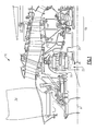
Figure 1 is a partial cross-sectional view of a front portion of a gas turbine engine illustrating a turbo fan, epicyclic gear train and a compressor section. -
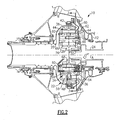
Figure 2 is a cross-sectional view of the epicyclic gear train shown inFig. 1 . -
Figure 3 is an end view of the epicyclic gear train taken along line 3-3 inFigure 2 with a pair of star gears shown in phantom in an installation position. -
Figure 4 is an enlarged view of a portion of the epicyclic gear train shown inFigure 3 with a sun gear and star gears shown in phantom. -
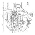
Figure 5 is an enlarged view of a portion of the epicyclic gear train shown inFigure 2 . - A portion of a
gas turbine engine 10 is shown schematically inFigure 1 . Theturbine engine 10 includes afixed housing 12 that is constructed from numerous pieces secured to one another. Acompressor section 14 havingcompressor hubs 16 with blades are driven by a turbine shaft (not shown) about an axis A. Aturbo fan 18 is supported on aturbo fan shaft 20 that is driven by acompressor shaft 24, which supports thecompressor hubs 16, through anepicyclic gear train 22. - In the example arrangement shown, the
epicyclic gear train 22 is a star gear train. Of course, the claimed invention also applies to other epicyclic gear trains such as a planetary arrangement. Referring toFigure 2 , theepicyclic gear train 22 includes asun gear 28 that is connected to thecompressor shaft 24, which provides rotational input, by asplined connection 30. Acarrier 34 is fixed to thehousing 12 by atorque frame 36. Thecarrier 34 supports intermediate gears (which arestar gears 32 in the arrangement shown) that are coupled to thesun gear 28 by meshedinterfaces 26 between the teeth of the sun andstar gears ring gear 38 surrounds thecarrier 34 and is coupled to thestar gears 32 bymeshed interfaces 44. Thering gear 38, which provides rotational output, is secured to theturbo fan shaft 20 byconnection 42. - The
torque frame 36 grounds thecarrier 34 to thehousing 12 in a known manner. For example,mounts 54 haveapertures 56 receiving fingers of thetorque frame 36, as shown inFigures 2 and3 .Pins 48 that extend throughspherical bearings 46 and bushings 52 secure the fingers to thecarrier 34.Fasteners 50 retain thepins 48 to thecarrier 34. - The
carrier 34 is a unitary structure manufactured from one piece for improved structural rigidity and ease of assembly. Thecarrier 34 includes spaced apartside walls 60 that are interconnected by themounts 54, which are generally wedge-shaped members, as best shown inFigure 3 . Themounts 54 andside walls 60 are unitary with one another. Themounts 54 have opposingcurved surfaces 58 that are in close proximity to thestar gears 32 and generally follow the curvature of the teeth of thestar gears 32 so that any oil on thecurved surfaces 58 will likely find its way to thestar gears 32 for additional lubrication. - The
mounts 54 are circumferentially spaced about thecarrier 34 to provideapertures 98 through which thestar gears 32 extend to engage thering gear 38. Returning toFigure 2 , theside walls 60 includeholes 62 for receiving a journal bearing 64 that supports each of thestar gears 32. Each journal bearing 64 is retained within thecarrier 34 byretainers 66 fastened to theside walls 60. -
Oil baffles 68 are arranged between theside walls 60 near each of themounts 54, best shown inFigure 2 . Referring toFigures 4 and5 , thebaffles 68 includeends 72 that abut themounts 54, in the example shown. Thebaffles 68 also include opposingcurved surfaces 70 arranged in close proximity to thestar gears 28. Thecurved surfaces gear pockets 102 that receive thestar gears 32. Agear pocket 104, which receives thesun gear 28, is also provided between asurface 73 on each of thebaffles 68 opposite theends 72. - In one example, one of the
side walls 60 includesholes 74 that receivefasteners 76 which secure each of thebaffles 68 to thecarrier 34. Thebaffles 68 include a lubrication passage provided by aprimary passage 86 that fluidly communicates with alubricant distributor 78. Thelubricant distributor 78 is fed oil from a lubricant supply 96. In one example, thebaffles 68 includeopenings 82 that receive atube 80 extending through ahole 83 in theside wall 60. Seals 84 seal thetube 80 to the opening 82 andlubricant distributor 78.Other tubes 92 havingseals 84 are used to provide oil to anexternal spray bar 94 through another lubrication passage (spray bar passage 93 that extends through one of the baffles 68). Theexternal spray bar 94 is secured to thecarrier 34 and sprays oil in the vicinity of thesun gear 28 near the splined connection 30 (shown inFigures 2 and5 ). - The
primary passage 86 is in communication with first andsecond passages 88, 90 that spray oil on the teeth of the sun and star gears 28, 32. In the example shown, the first andsecond passages 88, 90 are arranged ninety degrees from one another. - With the oil baffles 68, lubricant distribution is integrated into the baffle so that separate components are eliminated. The
baffles 68 can be constructed from a different, lighter weight material than thecarrier 34. - The
example carrier 34 is constructed from one piece, which improves the structural integrity of the carrier. Acentral opening 100 is machined in at least one of theside walls 60 and provides thegear pocket 104. Gear pockets 102 are machined between theside walls 60 and mounts 54 for each of the star gears 32 andform apertures 98 at an outer circumference of thecarrier 34. Referring toFigure 3 , the star gears 32 are inserted into thecentral opening 100 and moved radially outwardly so that they extend through theapertures 98 and are preferably in abutment with the mounts 54 (position indicated by dashed lines inFigure 3 ). In this position, there is an adequate gap, t, between the teeth of adjacent star gears 32 to accommodate a width, w, of theend 72 of thebaffles 68. Once thebaffles 68 have been inserted, the star gears 32 can be repositioned, as shown by the solid lines, and thesun gear 28 can be inserted into thecentral opening 100 so that it meshes with the star gears 32. Thebaffles 68 are secured to thecarrier 34 usingfasteners 76. Thetubes - Although a preferred embodiment of this invention has been disclosed, a worker of ordinary skill in this art would recognize that certain modifications would come within the scope of this invention. For that reason, the following claims should be studied to determine the true scope and content of this invention.
Claims (3)
- A method of assembling an epicyclic gear train (22) employable to drive a turbo fan (18) of a gas turbine engine (10), the method comprising the steps of:a) providing a carrier (34) that includes spaced apart side walls (60) and circumferentially spaced mounts (54) interconnecting the walls (60) in a one-piece unitary structure, spaced apart apertures (98) provided between the mounts (54) at an outer circumference of the carrier (34), gear pockets (102) provided between the walls (60) and mounts (54) extending to the apertures (98), and a central opening (100) in at least one of the walls (60);b) inserting intermediate gears (32) through the central opening (100) and moving the intermediate gears (32) radially outwardly into the gear pockets (102) so that they extend through the apertures (98) and are in abutment with the mounts (54);c) inserting oil baffles (68) into the carrier (34) so that they are arranged between the side walls (60) adjacent to the mounts (54) and securing the oil baffles (68) to the carrier (34) near the intermediate gears (32);d) repositioning the intermediate gears (32) by moving the intermediate gears (32) radially inwardly into their operational positions in the gear pockets (102);e) inserting a sun gear (28) through the central opening (100) to intermesh with the intermediate gears (32); andf) securing a torque frame (36) to the mounts (54), the torque frame (36) being fixed relative to a housing (12).
- The method according to claim 1, wherein step c) includes bolting the oil baffles (68) to one of the walls (60).
- The method according to claim 1 or claim 2, comprising inserting tubes (80) through holes (83) in the carrier (34) each to communicate with a lubrication passage (86) in the oil baffles (68).
Applications Claiming Priority (2)
| Application Number | Priority Date | Filing Date | Title |
|---|---|---|---|
| US11/481,112 US7704178B2 (en) | 2006-07-05 | 2006-07-05 | Oil baffle for gas turbine fan drive gear system |
| EP07252647.8A EP1876338B1 (en) | 2006-07-05 | 2007-06-29 | Gas turbine engine with oil baffle for a fan drive gear system |
Related Parent Applications (2)
| Application Number | Title | Priority Date | Filing Date |
|---|---|---|---|
| EP07252647.8 Division | 2007-06-29 | ||
| EP07252647.8A Division EP1876338B1 (en) | 2006-07-05 | 2007-06-29 | Gas turbine engine with oil baffle for a fan drive gear system |
Publications (2)
| Publication Number | Publication Date |
|---|---|
| EP2546494A1 EP2546494A1 (en) | 2013-01-16 |
| EP2546494B1 true EP2546494B1 (en) | 2014-10-29 |
Family
ID=38565432
Family Applications (2)
| Application Number | Title | Priority Date | Filing Date |
|---|---|---|---|
| EP07252647.8A Active EP1876338B1 (en) | 2006-07-05 | 2007-06-29 | Gas turbine engine with oil baffle for a fan drive gear system |
| EP12180834.9A Active EP2546494B1 (en) | 2006-07-05 | 2007-06-29 | Assembly method for a gas turbine fan drive gear system |
Family Applications Before (1)
| Application Number | Title | Priority Date | Filing Date |
|---|---|---|---|
| EP07252647.8A Active EP1876338B1 (en) | 2006-07-05 | 2007-06-29 | Gas turbine engine with oil baffle for a fan drive gear system |
Country Status (3)
| Country | Link |
|---|---|
| US (12) | US7704178B2 (en) |
| EP (2) | EP1876338B1 (en) |
| JP (1) | JP4722086B2 (en) |
Families Citing this family (150)
| Publication number | Priority date | Publication date | Assignee | Title |
|---|---|---|---|---|
| BE1016742A3 (en) * | 2005-08-31 | 2007-05-08 | Hansen Transmissions Int | A PLANETARY GEAR CONSTRUCTION. |
| US7926260B2 (en) * | 2006-07-05 | 2011-04-19 | United Technologies Corporation | Flexible shaft for gas turbine engine |
| US8585538B2 (en) | 2006-07-05 | 2013-11-19 | United Technologies Corporation | Coupling system for a star gear train in a gas turbine engine |
| US8667688B2 (en) * | 2006-07-05 | 2014-03-11 | United Technologies Corporation | Method of assembly for gas turbine fan drive gear system |
| US7704178B2 (en) * | 2006-07-05 | 2010-04-27 | United Technologies Corporation | Oil baffle for gas turbine fan drive gear system |
| US9194255B2 (en) | 2006-07-05 | 2015-11-24 | United Technologies Corporation | Oil baffle for gas turbine fan drive gear system |
| US8708863B2 (en) * | 2006-08-15 | 2014-04-29 | United Technologies Corporation | Epicyclic gear train |
| US9976437B2 (en) * | 2006-08-15 | 2018-05-22 | United Technologies Corporation | Epicyclic gear train |
| US8858388B2 (en) * | 2006-08-15 | 2014-10-14 | United Technologies Corporation | Gas turbine engine gear train |
| US8939864B2 (en) | 2006-08-15 | 2015-01-27 | United Technologies Corporation | Gas turbine engine lubrication |
| US8753243B2 (en) * | 2006-08-15 | 2014-06-17 | United Technologies Corporation | Ring gear mounting arrangement with oil scavenge scheme |
| US10107231B2 (en) | 2006-08-15 | 2018-10-23 | United Technologies Corporation | Gas turbine engine with geared architecture |
| US20120213628A1 (en) * | 2006-08-15 | 2012-08-23 | Mccune Michael E | Gas turbine engine with geared architecture |
| US7662059B2 (en) * | 2006-10-18 | 2010-02-16 | United Technologies Corporation | Lubrication of windmilling journal bearings |
| US10151248B2 (en) * | 2007-10-03 | 2018-12-11 | United Technologies Corporation | Dual fan gas turbine engine and gear train |
| US20090188334A1 (en) | 2008-01-25 | 2009-07-30 | United Technologies Corp. | Accessory Gearboxes and Related Gas Turbine Engine Systems |
| US20140174056A1 (en) | 2008-06-02 | 2014-06-26 | United Technologies Corporation | Gas turbine engine with low stage count low pressure turbine |
| US8128021B2 (en) | 2008-06-02 | 2012-03-06 | United Technologies Corporation | Engine mount system for a turbofan gas turbine engine |
| JP5155903B2 (en) * | 2009-02-16 | 2013-03-06 | 三菱重工業株式会社 | Planetary gearbox |
| FR2942284B1 (en) * | 2009-02-16 | 2011-03-04 | Snecma | LUBRICATION AND COOLING OF AN EPICYCLOIDAL GEAR TRAIN REDUCER |
| US8511055B2 (en) * | 2009-05-22 | 2013-08-20 | United Technologies Corporation | Apparatus and method for providing damper liquid in a gas turbine |
| US9784181B2 (en) * | 2009-11-20 | 2017-10-10 | United Technologies Corporation | Gas turbine engine architecture with low pressure compressor hub between high and low rotor thrust bearings |
| US8439637B2 (en) * | 2009-11-20 | 2013-05-14 | United Technologies Corporation | Bellows preload and centering spring for a fan drive gear system |
| US8672801B2 (en) | 2009-11-30 | 2014-03-18 | United Technologies Corporation | Mounting system for a planetary gear train in a gas turbine engine |
| JP4785976B1 (en) | 2010-04-13 | 2011-10-05 | 川崎重工業株式会社 | Planetary gear set |
| US10041442B2 (en) | 2010-06-11 | 2018-08-07 | United Technologies Corporation | Variable area fan nozzle |
| DE102011011796A1 (en) | 2010-08-19 | 2012-02-23 | Robert Bosch Gmbh | Pressure oil lubrication of the gears of a planetary gear |
| DE102011103725A1 (en) * | 2010-08-19 | 2012-03-22 | Robert Bosch Gmbh | Pressure oil lubrication of the gears of a planetary gear |
| US9995174B2 (en) | 2010-10-12 | 2018-06-12 | United Technologies Corporation | Planetary gear system arrangement with auxiliary oil system |
| US8813469B2 (en) | 2010-10-12 | 2014-08-26 | United Technologies Corporation | Planetary gear system arrangement with auxiliary oil system |
| US20120260669A1 (en) * | 2011-04-15 | 2012-10-18 | Davis Todd A | Front centerbody support for a gas turbine engine |
| US8360714B2 (en) | 2011-04-15 | 2013-01-29 | United Technologies Corporation | Gas turbine engine front center body architecture |
| US10605167B2 (en) | 2011-04-15 | 2020-03-31 | United Technologies Corporation | Gas turbine engine front center body architecture |
| US9541007B2 (en) | 2011-04-15 | 2017-01-10 | United Technologies Corporation | Coupling shaft for gas turbine fan drive gear system |
| US8366385B2 (en) * | 2011-04-15 | 2013-02-05 | United Technologies Corporation | Gas turbine engine front center body architecture |
| US8900083B2 (en) | 2011-04-27 | 2014-12-02 | United Technologies Corporation | Fan drive gear system integrated carrier and torque frame |
| US8777793B2 (en) * | 2011-04-27 | 2014-07-15 | United Technologies Corporation | Fan drive planetary gear system integrated carrier and torque frame |
| US9631558B2 (en) | 2012-01-03 | 2017-04-25 | United Technologies Corporation | Geared architecture for high speed and small volume fan drive turbine |
| US8770922B2 (en) | 2011-06-08 | 2014-07-08 | United Technologies Corporation | Flexible support structure for a geared architecture gas turbine engine |
| US9239012B2 (en) | 2011-06-08 | 2016-01-19 | United Technologies Corporation | Flexible support structure for a geared architecture gas turbine engine |
| US8814503B2 (en) | 2011-06-08 | 2014-08-26 | United Technologies Corporation | Flexible support structure for a geared architecture gas turbine engine |
| US9133729B1 (en) | 2011-06-08 | 2015-09-15 | United Technologies Corporation | Flexible support structure for a geared architecture gas turbine engine |
| US8297916B1 (en) * | 2011-06-08 | 2012-10-30 | United Technologies Corporation | Flexible support structure for a geared architecture gas turbine engine |
| US9523422B2 (en) | 2011-06-08 | 2016-12-20 | United Technologies Corporation | Flexible support structure for a geared architecture gas turbine engine |
| US8690721B2 (en) * | 2011-08-02 | 2014-04-08 | United Technologies Corporation | Journal pin oil supply for gear system |
| US8899916B2 (en) | 2011-08-30 | 2014-12-02 | United Technologies Corporation | Torque frame and asymmetric journal bearing for fan drive gear system |
| EP2584153B1 (en) | 2011-10-17 | 2019-01-09 | United Technologies Corporation | Gas turbine engine and method of disassembly |
| CA2789325C (en) * | 2011-10-27 | 2015-04-07 | United Technologies Corporation | Gas turbine engine front center body architecture |
| CA2789465C (en) * | 2011-10-27 | 2016-08-09 | United Technologies Corporation | Gas turbine engine front center body architecture |
| ITTO20111007A1 (en) * | 2011-11-03 | 2013-05-04 | Avio Spa | EPICYCLOIDAL ROTISM |
| EP2610461B1 (en) * | 2011-12-30 | 2019-10-23 | United Technologies Corporation | Turbine engine |
| EP3088702A1 (en) * | 2011-12-30 | 2016-11-02 | United Technologies Corporation | Gas turbine engine gear train |
| EP2610464B1 (en) * | 2011-12-30 | 2018-10-31 | United Technologies Corporation | Gas Turbine engine |
| US9004849B2 (en) | 2012-01-10 | 2015-04-14 | United Technologies Corporation | Gas turbine engine forward bearing compartment architecture |
| US9416677B2 (en) | 2012-01-10 | 2016-08-16 | United Technologies Corporation | Gas turbine engine forward bearing compartment architecture |
| US8771124B2 (en) | 2012-01-16 | 2014-07-08 | Hamilton Sundstrand Corporation | Carrier for planetary gear system |
| US8402741B1 (en) * | 2012-01-31 | 2013-03-26 | United Technologies Corporation | Gas turbine engine shaft bearing configuration |
| US9038366B2 (en) | 2012-01-31 | 2015-05-26 | United Technologies Corporation | LPC flowpath shape with gas turbine engine shaft bearing configuration |
| US10145266B2 (en) * | 2012-01-31 | 2018-12-04 | United Technologies Corporation | Gas turbine engine shaft bearing arrangement |
| US10400629B2 (en) | 2012-01-31 | 2019-09-03 | United Technologies Corporation | Gas turbine engine shaft bearing configuration |
| US8720306B2 (en) | 2012-01-31 | 2014-05-13 | United Technologies Corporation | Turbine engine gearbox |
| US9169781B2 (en) | 2012-01-31 | 2015-10-27 | United Technologies Corporation | Turbine engine gearbox |
| US8863491B2 (en) | 2012-01-31 | 2014-10-21 | United Technologies Corporation | Gas turbine engine shaft bearing configuration |
| FR2987402B1 (en) * | 2012-02-23 | 2015-02-27 | Snecma | DEVICE FOR LUBRICATING AN EPICYCLOIDAL REDUCER COMPATIBLE WITH A MODULAR ASSEMBLY. |
| US9850821B2 (en) | 2012-02-28 | 2017-12-26 | United Technologies Corporation | Gas turbine engine with fan-tied inducer section |
| US20130219859A1 (en) * | 2012-02-29 | 2013-08-29 | Gabriel L. Suciu | Counter rotating low pressure compressor and turbine each having a gear system |
| EP3855003B1 (en) * | 2012-03-23 | 2022-09-28 | Raytheon Technologies Corporation | Planetary gear system arrangement with auxiliary oil system |
| US8961112B2 (en) * | 2012-03-26 | 2015-02-24 | United Technologies Corporation | Torque frame bushing arrangement for gas turbine engine fan drive gear system |
| US8529197B1 (en) * | 2012-03-28 | 2013-09-10 | United Technologies Corporation | Gas turbine engine fan drive gear system damper |
| US9057284B2 (en) * | 2012-04-30 | 2015-06-16 | United Technologies Corporation | Manifold for geared turbofan engine |
| US9163717B2 (en) | 2012-04-30 | 2015-10-20 | United Technologies Corporation | Multi-piece fluid manifold for gas turbine engine |
| US8484942B1 (en) | 2012-05-30 | 2013-07-16 | United Technologies Corporation | Planetary gear system arrangement with auxiliary oil system |
| US20150308351A1 (en) | 2012-05-31 | 2015-10-29 | United Technologies Corporation | Fundamental gear system architecture |
| US9476323B2 (en) | 2012-05-31 | 2016-10-25 | United Technologies Corporation | Turbine gear assembly support having symmetrical removal features |
| US8756908B2 (en) | 2012-05-31 | 2014-06-24 | United Technologies Corporation | Fundamental gear system architecture |
| US8572943B1 (en) | 2012-05-31 | 2013-11-05 | United Technologies Corporation | Fundamental gear system architecture |
| US9145830B2 (en) | 2012-06-04 | 2015-09-29 | United Technologies Corporation | Turbomachine geared architecture support assembly |
| US9115598B2 (en) * | 2012-06-05 | 2015-08-25 | United Technologies Corporation | Front bearing support for a fan drive gear system |
| US9896968B2 (en) | 2012-07-30 | 2018-02-20 | United Technologies Corporation | Forward compartment baffle arrangement for a geared turbofan engine |
| US9410447B2 (en) | 2012-07-30 | 2016-08-09 | United Technologies Corporation | Forward compartment service system for a geared architecture gas turbine engine |
| US8727935B2 (en) * | 2012-07-30 | 2014-05-20 | United Technologies Corporation | Fan drive gear system torque frame pin retainer |
| US9328818B2 (en) * | 2012-09-21 | 2016-05-03 | United Technologies Corporation | Gear carrier flex mount lubrication |
| US8753065B2 (en) | 2012-09-27 | 2014-06-17 | United Technologies Corporation | Method for setting a gear ratio of a fan drive gear system of a gas turbine engine |
| EP2901033A4 (en) * | 2012-09-28 | 2016-05-25 | United Technologies Corp | Method of assembly for gas turbine fan drive gear system |
| FR2996272B1 (en) * | 2012-09-28 | 2015-05-15 | Snecma | LUBRICATING OIL TRANSFER DEVICE |
| WO2014055122A1 (en) * | 2012-10-01 | 2014-04-10 | United Technologies Corporation | Geared turbofan high gearbox power density |
| US9182011B2 (en) * | 2012-10-01 | 2015-11-10 | United Technologies Corporation | Fan drive gear system flexible support features |
| GB201218310D0 (en) * | 2012-10-12 | 2012-11-28 | Rolls Royce Plc | Oil Scavenge arrangement |
| US8900090B2 (en) * | 2012-11-30 | 2014-12-02 | United Technologies Corporation | Geared architecture gas turbine engine with improved lubrication and misalignment tolerant roller bearing system |
| US9249685B2 (en) * | 2012-12-17 | 2016-02-02 | United Technologies Corporation | Fan drive gear system assembly guide |
| US10247020B2 (en) | 2013-01-15 | 2019-04-02 | United Technologies Corporation | Fluid collection gutter for a geared turbine engine |
| EP2946131B1 (en) | 2013-01-15 | 2020-03-04 | United Technologies Corporation | Turbine engine |
| EP2954186B1 (en) * | 2013-02-06 | 2018-01-17 | United Technologies Corporation | Oil baffles in carrier for a fan drive gear system |
| US10605112B2 (en) * | 2013-03-04 | 2020-03-31 | United Technologies Corporation | Fan drive gear system spline oil lubrication scheme |
| US9863326B2 (en) * | 2013-03-12 | 2018-01-09 | United Technologies Corporation | Flexible coupling for geared turbine engine |
| EP2949882B1 (en) * | 2013-06-03 | 2017-08-23 | United Technologies Corporation | Geared architecture for high speed and small volume fan drive turbine |
| EP3014147A1 (en) * | 2013-06-28 | 2016-05-04 | General Electric Company | Lightweight gear assembly for epicyclic gearbox |
| FR3009594B1 (en) * | 2013-08-08 | 2016-12-09 | Snecma | EPICYCLOIDAL TRAIN REDUCER WITH FLUID TRANSFER PIPES, AND AIRCRAFT TURBOMACHINE (S) FOR AN AIRCRAFT WITH SUCH REDUCER |
| US9745862B2 (en) | 2013-08-21 | 2017-08-29 | United Technologies Corporation | Reduced misalignment gear system |
| US8857149B1 (en) * | 2013-08-26 | 2014-10-14 | United Technologies Corporation | Torque connector lubrication scuppers |
| FR3010449B1 (en) * | 2013-09-06 | 2015-09-25 | Snecma | ROTARY ASSEMBLY COMPRISING A TRANSMISSION MEMBER AND AN OIL DISTRIBUTION SYSTEM |
| CN105264234B (en) * | 2013-09-06 | 2017-09-19 | 三菱重工压缩机有限公司 | Rotating machinery |
| FR3013385B1 (en) * | 2013-11-21 | 2015-11-13 | Snecma | PRE-SEALED SPEAKER DURING MODULAR DISASSEMBLY OF A REDUCING TURBOREACTOR |
| EP3084181B1 (en) | 2013-12-20 | 2021-11-03 | Raytheon Technologies Corporation | Geared turbofan with improved gear system maintainability |
| US9739205B2 (en) * | 2013-12-23 | 2017-08-22 | United Technologies Corporation | Geared turbofan with a gearbox upstream of a fan drive turbine |
| US10161409B2 (en) | 2013-12-30 | 2018-12-25 | United Technologies Corporation | Fan drive gear system including a two-piece fan shaft with lubricant transfer leakage recapture |
| EP3097324B1 (en) | 2014-01-20 | 2019-04-03 | United Technologies Corporation | Lightweight journal support pin |
| CN105247248B (en) | 2014-02-20 | 2017-12-22 | 三菱重工压缩机有限公司 | Rotatory mechanical system |
| US10280843B2 (en) | 2014-03-07 | 2019-05-07 | United Technologies Corporation | Geared turbofan with integral front support and carrier |
| US10196926B2 (en) * | 2014-04-11 | 2019-02-05 | United Technologies Corporation | Lubricating a rotating component during forward and/or reverse rotation |
| FR3020658B1 (en) * | 2014-04-30 | 2020-05-15 | Safran Aircraft Engines | LUBRICATION OIL RECOVERY HOOD FOR TURBOMACHINE EQUIPMENT |
| US10731510B2 (en) | 2014-05-16 | 2020-08-04 | Raython Technologies Group | Gas turbine engine with fluid damper |
| US9976490B2 (en) * | 2014-07-01 | 2018-05-22 | United Technologies Corporation | Geared gas turbine engine with oil deaerator |
| US20160025187A1 (en) * | 2014-07-25 | 2016-01-28 | Caterpillar Inc. | Planetary gear system |
| US9695710B2 (en) | 2014-09-08 | 2017-07-04 | United Technologies Corporation | Oil transfer bearing |
| US9897010B2 (en) * | 2015-03-30 | 2018-02-20 | Honeywell International Inc. | Air turbine starter systems including gearbox-integrated clutch modules and gas turbine engines employing the same |
| US20160298485A1 (en) * | 2015-04-13 | 2016-10-13 | United Technologies Corporation | Speed sensor for a gas turbine engine |
| GB201510050D0 (en) | 2015-06-10 | 2015-07-22 | Rolls Royce Plc | A geared gas turbine engine |
| US10119465B2 (en) | 2015-06-23 | 2018-11-06 | United Technologies Corporation | Geared turbofan with independent flexible ring gears and oil collectors |
| US10634237B2 (en) | 2015-06-24 | 2020-04-28 | United Technologies Corporation | Lubricant delivery system for planetary fan drive gear system |
| US10767753B2 (en) | 2015-06-25 | 2020-09-08 | Raytheon Technologies Corporation | Rolling element cage for geared turbofan |
| US9771871B2 (en) * | 2015-07-07 | 2017-09-26 | United Technologies Corporation | FBO torque reducing feature in fan shaft |
| US11066945B2 (en) | 2015-07-15 | 2021-07-20 | Raytheon Technologies Corporation | Fluid collection gutter for a geared turbine engine |
| JP6628518B2 (en) * | 2015-07-31 | 2020-01-08 | 川崎重工業株式会社 | Gear cooling structure |
| US10495004B2 (en) | 2015-09-17 | 2019-12-03 | General Electric Company | Multi-directional gearbox deflection limiter for a gas turbine engine |
| US9772027B2 (en) | 2015-10-08 | 2017-09-26 | GM Global Technology Operations LLC | Variable baffle that reduces oil at the gear mesh |
| GB201518227D0 (en) | 2015-10-15 | 2015-12-02 | Rolls Royce Plc | A geared gas turbine engine |
| US10082203B2 (en) * | 2016-05-20 | 2018-09-25 | United Technologies Corporation | Low-cost epicyclic gear carrier and method of making the same |
| FR3052213B1 (en) * | 2016-06-07 | 2018-05-18 | Safran Transmission Systems | METHOD FOR ASSEMBLING A SATELLITE HOLDER |
| GB201611893D0 (en) * | 2016-07-08 | 2016-08-24 | Rolls Royce Plc | A geared gas turbine engine and a gearbox |
| FR3058493B1 (en) * | 2016-11-07 | 2018-11-16 | Safran Transmission Systems | SATELLITE CARRIER FOR AN EPICYCLOIDAL TRAIN SPEED REDUCER |
| US10669948B2 (en) | 2017-01-03 | 2020-06-02 | Raytheon Technologies Corporation | Geared turbofan with non-epicyclic gear reduction system |
| EP3473892A1 (en) | 2017-10-18 | 2019-04-24 | Ge Avio S.r.l. | Gearbox for a gas turbine engine |
| EP3473893B1 (en) * | 2017-10-19 | 2020-06-17 | Ge Avio S.r.l. | Lubrication fluid collection in a gearbox of a gas turbine engine |
| GB201720391D0 (en) * | 2017-12-07 | 2018-01-24 | Rolls Royce Plc | A gas turbine engine |
| US10724445B2 (en) | 2018-01-03 | 2020-07-28 | Raytheon Technologies Corporation | Method of assembly for fan drive gear system with rotating carrier |
| IT201800003231A1 (en) | 2018-03-02 | 2019-09-02 | Ge Avio Srl | LUBRICANT RECOVERY SYSTEM FOR A GEAR GROUP |
| DE102018106488A1 (en) * | 2018-03-20 | 2019-09-26 | Rolls-Royce Deutschland Ltd & Co Kg | Gas turbine engine and method of introducing oil into a transmission assembly |
| GB201809373D0 (en) * | 2018-06-07 | 2018-07-25 | Rolls Royce Plc | A gearbox and a geared gas turbine engine |
| US11092020B2 (en) | 2018-10-18 | 2021-08-17 | Raytheon Technologies Corporation | Rotor assembly for gas turbine engines |
| US11313438B2 (en) * | 2019-07-18 | 2022-04-26 | Rolls-Royce Plc | Turbofan gas turbine engine with gearbox |
| US11274729B2 (en) * | 2019-07-18 | 2022-03-15 | Rolls-Royce Plc | Turbofan gas turbine engine with gearbox |
| FR3099220B1 (en) * | 2019-07-23 | 2021-09-24 | Safran Trans Systems | Planetary gear reducer for a turbomachine |
| US11105395B2 (en) * | 2019-10-23 | 2021-08-31 | Pratt & Whitney Canada Corp. | Planetary gear assembly and method of operating same |
| US11162575B2 (en) | 2019-11-20 | 2021-11-02 | Raytheon Technologies Corporation | Geared architecture for gas turbine engine |
| FR3110194B1 (en) * | 2020-05-13 | 2022-11-18 | Safran Aircraft Engines | AIRCRAFT TURBOMACHINE COMPRISING A DEVICE FOR LUBRICATING A BEARING |
| US11674440B2 (en) | 2021-02-09 | 2023-06-13 | Raytheon Technologies Corporation | Geared gas turbine engine with combined spray bar and scavenge component |
| FR3124564B1 (en) * | 2021-06-24 | 2023-07-21 | Safran Trans Systems | SATELLITE CARRIER FOR AN AIRCRAFT TURBOMACHINE SPEED REDUCER |
| CN113669420B (en) * | 2021-10-22 | 2021-12-28 | 深圳柏成科技有限公司 | New forms of energy passenger train planetary transmission |
| US11598407B1 (en) * | 2022-02-16 | 2023-03-07 | Pratt & Whitney Canada Corp. | Epicyclic gear train of aircraft powerplant |
Family Cites Families (124)
| Publication number | Priority date | Publication date | Assignee | Title |
|---|---|---|---|---|
| US2258792A (en) | 1941-04-12 | 1941-10-14 | Westinghouse Electric & Mfg Co | Turbine blading |
| US2591743A (en) * | 1948-11-23 | 1952-04-08 | Gen Electric | Cage construction for planetary gearing |
| US3021731A (en) | 1951-11-10 | 1962-02-20 | Wilhelm G Stoeckicht | Planetary gear transmission |
| US2936655A (en) | 1955-11-04 | 1960-05-17 | Gen Motors Corp | Self-aligning planetary gearing |
| US3194487A (en) | 1963-06-04 | 1965-07-13 | United Aircraft Corp | Noise abatement method and apparatus |
| US3287906A (en) | 1965-07-20 | 1966-11-29 | Gen Motors Corp | Cooled gas turbine vanes |
| US3352178A (en) | 1965-11-15 | 1967-11-14 | Gen Motors Corp | Planetary gearing |
| US3412560A (en) | 1966-08-03 | 1968-11-26 | Gen Motors Corp | Jet propulsion engine with cooled combustion chamber, fuel heater, and induced air-flow |
| US3527121A (en) | 1968-08-26 | 1970-09-08 | Gen Motors Corp | Carrier |
| GB1291257A (en) | 1969-02-19 | 1972-10-04 | G K N Transmissions Ltd Former | Lubrication system for change-speed epicyclic gearing |
| US3664612A (en) | 1969-12-22 | 1972-05-23 | Boeing Co | Aircraft engine variable highlight inlet |
| GB1350431A (en) | 1971-01-08 | 1974-04-18 | Secr Defence | Gearing |
| US3892358A (en) | 1971-03-17 | 1975-07-01 | Gen Electric | Nozzle seal |
| US3765623A (en) | 1971-10-04 | 1973-10-16 | Mc Donnell Douglas Corp | Air inlet |
| US3747343A (en) | 1972-02-10 | 1973-07-24 | United Aircraft Corp | Low noise prop-fan |
| GB1418905A (en) | 1972-05-09 | 1975-12-24 | Rolls Royce | Gas turbine engines |
| US3843277A (en) | 1973-02-14 | 1974-10-22 | Gen Electric | Sound attenuating inlet duct |
| US3853432A (en) | 1973-08-29 | 1974-12-10 | Avco Corp | Differential gas turbine engine |
| US3988889A (en) | 1974-02-25 | 1976-11-02 | General Electric Company | Cowling arrangement for a turbofan engine |
| US3932058A (en) | 1974-06-07 | 1976-01-13 | United Technologies Corporation | Control system for variable pitch fan propulsor |
| US3935558A (en) | 1974-12-11 | 1976-01-27 | United Technologies Corporation | Surge detector for turbine engines |
| US4130872A (en) | 1975-10-10 | 1978-12-19 | The United States Of America As Represented By The Secretary Of The Air Force | Method and system of controlling a jet engine for avoiding engine surge |
| GB1516041A (en) | 1977-02-14 | 1978-06-28 | Secr Defence | Multistage axial flow compressor stators |
| US4240250A (en) | 1977-12-27 | 1980-12-23 | The Boeing Company | Noise reducing air inlet for gas turbine engines |
| US4271928A (en) | 1978-07-11 | 1981-06-09 | Rolls-Royce Limited | Lubricant supply device |
| GB2041090A (en) | 1979-01-31 | 1980-09-03 | Rolls Royce | By-pass gas turbine engines |
| US4284174A (en) | 1979-04-18 | 1981-08-18 | Avco Corporation | Emergency oil/mist system |
| US4220171A (en) | 1979-05-14 | 1980-09-02 | The United States Of America As Represented By The Administrator Of The National Aeronautics And Space Administration | Curved centerline air intake for a gas turbine engine |
| US4289360A (en) | 1979-08-23 | 1981-09-15 | General Electric Company | Bearing damper system |
| DE2940446C2 (en) | 1979-10-05 | 1982-07-08 | B. Braun Melsungen Ag, 3508 Melsungen | Cultivation of animal cells in suspension and monolayer cultures in fermentation vessels |
| US4378711A (en) * | 1980-09-29 | 1983-04-05 | Caterpillar Tractor Co. | Planetary mechanism having a fluid baffle |
| US4478551A (en) | 1981-12-08 | 1984-10-23 | United Technologies Corporation | Turbine exhaust case design |
| DE3410977C2 (en) * | 1984-03-16 | 1986-01-09 | BHS-Bayerische Berg-, Hütten- und Salzwerke AG, 8000 München | Planetary gear |
| US4722357A (en) | 1986-04-11 | 1988-02-02 | United Technologies Corporation | Gas turbine engine nacelle |
| US4696156A (en) | 1986-06-03 | 1987-09-29 | United Technologies Corporation | Fuel and oil heat management system for a gas turbine engine |
| GB8630754D0 (en) * | 1986-12-23 | 1987-02-04 | Rolls Royce Plc | Turbofan gas turbine engine |
| US4914904A (en) * | 1988-11-09 | 1990-04-10 | Avco Corporation | Oil cooler for fan jet engines |
| US4979362A (en) | 1989-05-17 | 1990-12-25 | Sundstrand Corporation | Aircraft engine starting and emergency power generating system |
| US5058617A (en) | 1990-07-23 | 1991-10-22 | General Electric Company | Nacelle inlet for an aircraft gas turbine engine |
| US5141400A (en) | 1991-01-25 | 1992-08-25 | General Electric Company | Wide chord fan blade |
| US5102379A (en) | 1991-03-25 | 1992-04-07 | United Technologies Corporation | Journal bearing arrangement |
| IT1250861B (en) | 1991-11-12 | 1995-04-21 | Fiat Avio Spa | EPICYCLOIDAL SPEED REDUCER SUITABLE TO BE INSERTED IN THE TRANSMISSION BETWEEN A GAS TURBINE AND THE AIR COMPRESSOR OF AN AIRCRAFT ENGINE. |
| JP3175308B2 (en) | 1992-06-18 | 2001-06-11 | 住友化学工業株式会社 | Thermoplastic elastomer composition |
| US5317877A (en) | 1992-08-03 | 1994-06-07 | General Electric Company | Intercooled turbine blade cooling air feed system |
| US5447411A (en) | 1993-06-10 | 1995-09-05 | Martin Marietta Corporation | Light weight fan blade containment system |
| US5466198A (en) * | 1993-06-11 | 1995-11-14 | United Technologies Corporation | Geared drive system for a bladed propulsor |
| US5361580A (en) | 1993-06-18 | 1994-11-08 | General Electric Company | Gas turbine engine rotor support system |
| US5524847A (en) | 1993-09-07 | 1996-06-11 | United Technologies Corporation | Nacelle and mounting arrangement for an aircraft engine |
| JP2947698B2 (en) * | 1993-09-17 | 1999-09-13 | 大阪製鎖造機株式会社 | Reduction gear for vertical roller mill |
| US5472383A (en) * | 1993-12-27 | 1995-12-05 | United Technologies Corporation | Lubrication system for a planetary gear train |
| RU2082824C1 (en) | 1994-03-10 | 1997-06-27 | Московский государственный авиационный институт (технический университет) | Method of protection of heat-resistant material from effect of high-rapid gaseous flow of corrosive media (variants) |
| US5433674A (en) * | 1994-04-12 | 1995-07-18 | United Technologies Corporation | Coupling system for a planetary gear train |
| US5778659A (en) | 1994-10-20 | 1998-07-14 | United Technologies Corporation | Variable area fan exhaust nozzle having mechanically separate sleeve and thrust reverser actuation systems |
| US5915917A (en) | 1994-12-14 | 1999-06-29 | United Technologies Corporation | Compressor stall and surge control using airflow asymmetry measurement |
| JP2969075B2 (en) | 1996-02-26 | 1999-11-02 | ジャパンゴアテックス株式会社 | Degassing device |
| US5634767A (en) | 1996-03-29 | 1997-06-03 | General Electric Company | Turbine frame having spindle mounted liner |
| US5857836A (en) | 1996-09-10 | 1999-01-12 | Aerodyne Research, Inc. | Evaporatively cooled rotor for a gas turbine engine |
| US5975841A (en) | 1997-10-03 | 1999-11-02 | Thermal Corp. | Heat pipe cooling for turbine stators |
| US5985470A (en) | 1998-03-16 | 1999-11-16 | General Electric Company | Thermal/environmental barrier coating system for silicon-based materials |
| US5937817A (en) * | 1998-06-23 | 1999-08-17 | Harley-Davidson Motor Company | Dry sump oil cooling system |
| US6158210A (en) | 1998-12-03 | 2000-12-12 | General Electric Company | Gear driven booster |
| US6517341B1 (en) | 1999-02-26 | 2003-02-11 | General Electric Company | Method to prevent recession loss of silica and silicon-containing materials in combustion gas environments |
| US6410148B1 (en) | 1999-04-15 | 2002-06-25 | General Electric Co. | Silicon based substrate with environmental/ thermal barrier layer |
| US6315815B1 (en) | 1999-12-16 | 2001-11-13 | United Technologies Corporation | Membrane based fuel deoxygenator |
| US6223616B1 (en) * | 1999-12-22 | 2001-05-01 | United Technologies Corporation | Star gear system with lubrication circuit and lubrication method therefor |
| US6318070B1 (en) | 2000-03-03 | 2001-11-20 | United Technologies Corporation | Variable area nozzle for gas turbine engines driven by shape memory alloy actuators |
| US6422791B1 (en) | 2000-04-04 | 2002-07-23 | Abb Vetco Gray Inc. | Riser to sleeve attachment for flexible keel joint |
| US6444335B1 (en) | 2000-04-06 | 2002-09-03 | General Electric Company | Thermal/environmental barrier coating for silicon-containing materials |
| EP1780387A3 (en) | 2000-09-05 | 2007-07-18 | Sudarshan Paul Dev | Nested core gas turbine engine |
| US6708482B2 (en) | 2001-11-29 | 2004-03-23 | General Electric Company | Aircraft engine with inter-turbine engine frame |
| US6607165B1 (en) | 2002-06-28 | 2003-08-19 | General Electric Company | Aircraft engine mount with single thrust link |
| US6814541B2 (en) | 2002-10-07 | 2004-11-09 | General Electric Company | Jet aircraft fan case containment design |
| US7021042B2 (en) | 2002-12-13 | 2006-04-04 | United Technologies Corporation | Geartrain coupling for a turbofan engine |
| FR2853382B1 (en) * | 2003-04-04 | 2006-04-28 | Hispano Suiza Sa | FLEXIBLE BONDING SYSTEM BETWEEN A SATELLITE HOLDER AND THE FIXED SUPPORT IN A SPEED REDUCER |
| US6709492B1 (en) | 2003-04-04 | 2004-03-23 | United Technologies Corporation | Planar membrane deoxygenator |
| DE10324362A1 (en) | 2003-05-27 | 2004-12-16 | A. Friedr. Flender Ag | Gear for driving a rotary tube |
| US6905303B2 (en) * | 2003-06-30 | 2005-06-14 | General Electric Company | Methods and apparatus for assembling gas turbine engines |
| US7104918B2 (en) * | 2003-07-29 | 2006-09-12 | Pratt & Whitney Canada Corp. | Compact epicyclic gear carrier |
| DE10334459A1 (en) * | 2003-07-29 | 2005-03-17 | Zf Friedrichshafen Ag | Guide disc assembly of a planet carrier for a planetary gear |
| JP4464669B2 (en) * | 2003-12-03 | 2010-05-19 | 株式会社小松製作所 | Wind speed booster |
| JP2005207472A (en) * | 2004-01-21 | 2005-08-04 | Nsk Ltd | Planetary mechanism power transmitting device and its carrier processing method |
| US7033301B2 (en) * | 2004-02-26 | 2006-04-25 | Ford Global Technologies, Llc | Planet pinion carrier assembly for Ravigneaux gearset |
| DE102004016246A1 (en) | 2004-04-02 | 2005-10-20 | Mtu Aero Engines Gmbh | Turbine, in particular low-pressure turbine, a gas turbine, in particular an aircraft engine |
| US7328580B2 (en) | 2004-06-23 | 2008-02-12 | General Electric Company | Chevron film cooled wall |
| JP4464233B2 (en) * | 2004-09-21 | 2010-05-19 | ジヤトコ株式会社 | Oil splitting structure in automatic transmission |
| DE102005004290B4 (en) | 2005-01-28 | 2006-11-02 | Gkn Driveline International Gmbh | Transmission module for variable torque distribution |
| DE102005004291B4 (en) | 2005-01-28 | 2007-05-31 | Gkn Driveline International Gmbh | Gear arrangement for variable torque distribution |
| GB0506685D0 (en) | 2005-04-01 | 2005-05-11 | Hopkins David R | A design to increase and smoothly improve the throughput of fluid (air or gas) through the inlet fan (or fans) of an aero-engine system |
| US7374403B2 (en) | 2005-04-07 | 2008-05-20 | General Electric Company | Low solidity turbofan |
| EP1928943B1 (en) | 2005-09-28 | 2014-07-09 | Entrotech Composites, LLC. | Linerless prepregs, composite articles therefrom, and related methods |
| US7490460B2 (en) * | 2005-10-19 | 2009-02-17 | General Electric Company | Gas turbine engine assembly and methods of assembling same |
| DE102005054088A1 (en) * | 2005-11-12 | 2007-05-16 | Mtu Aero Engines Gmbh | planetary gear |
| US7591754B2 (en) | 2006-03-22 | 2009-09-22 | United Technologies Corporation | Epicyclic gear train integral sun gear coupling design |
| BE1017135A3 (en) | 2006-05-11 | 2008-03-04 | Hansen Transmissions Int | A GEARBOX FOR A WIND TURBINE. |
| US20080003096A1 (en) | 2006-06-29 | 2008-01-03 | United Technologies Corporation | High coverage cooling hole shape |
| JP4911344B2 (en) | 2006-07-04 | 2012-04-04 | 株式会社Ihi | Turbofan engine |
| US8667688B2 (en) | 2006-07-05 | 2014-03-11 | United Technologies Corporation | Method of assembly for gas turbine fan drive gear system |
| US7704178B2 (en) * | 2006-07-05 | 2010-04-27 | United Technologies Corporation | Oil baffle for gas turbine fan drive gear system |
| US8585538B2 (en) | 2006-07-05 | 2013-11-19 | United Technologies Corporation | Coupling system for a star gear train in a gas turbine engine |
| US7926260B2 (en) | 2006-07-05 | 2011-04-19 | United Technologies Corporation | Flexible shaft for gas turbine engine |
| US8753243B2 (en) | 2006-08-15 | 2014-06-17 | United Technologies Corporation | Ring gear mounting arrangement with oil scavenge scheme |
| US7632064B2 (en) | 2006-09-01 | 2009-12-15 | United Technologies Corporation | Variable geometry guide vane for a gas turbine engine |
| US7662059B2 (en) | 2006-10-18 | 2010-02-16 | United Technologies Corporation | Lubrication of windmilling journal bearings |
| US8020665B2 (en) | 2006-11-22 | 2011-09-20 | United Technologies Corporation | Lubrication system with extended emergency operability |
| US8017188B2 (en) | 2007-04-17 | 2011-09-13 | General Electric Company | Methods of making articles having toughened and untoughened regions |
| US7950237B2 (en) | 2007-06-25 | 2011-05-31 | United Technologies Corporation | Managing spool bearing load using variable area flow nozzle |
| US20120124964A1 (en) | 2007-07-27 | 2012-05-24 | Hasel Karl L | Gas turbine engine with improved fuel efficiency |
| US8256707B2 (en) | 2007-08-01 | 2012-09-04 | United Technologies Corporation | Engine mounting configuration for a turbofan gas turbine engine |
| US8205432B2 (en) | 2007-10-03 | 2012-06-26 | United Technologies Corporation | Epicyclic gear train for turbo fan engine |
| US8348803B2 (en) | 2008-04-17 | 2013-01-08 | Kawasaki Jukogyo Kabushiki Kaisha | Planetary reduction gear apparatus |
| US8128021B2 (en) | 2008-06-02 | 2012-03-06 | United Technologies Corporation | Engine mount system for a turbofan gas turbine engine |
| US20100035719A1 (en) | 2008-08-06 | 2010-02-11 | Sheng Bor Wang | Epicyclic gearing |
| US8204453B2 (en) | 2008-08-20 | 2012-06-19 | Intel Mobile Communications GmbH | Method, apparatus and communication unit |
| US8058655B2 (en) | 2008-11-05 | 2011-11-15 | Ss Sc Ip, Llc | Vertical junction field effect transistors having sloped sidewalls and methods of making |
| US7997868B1 (en) | 2008-11-18 | 2011-08-16 | Florida Turbine Technologies, Inc. | Film cooling hole for turbine airfoil |
| US8307626B2 (en) | 2009-02-26 | 2012-11-13 | United Technologies Corporation | Auxiliary pump system for fan drive gear system |
| US8181441B2 (en) | 2009-02-27 | 2012-05-22 | United Technologies Corporation | Controlled fan stream flow bypass |
| US8172716B2 (en) | 2009-06-25 | 2012-05-08 | United Technologies Corporation | Epicyclic gear system with superfinished journal bearing |
| US9170616B2 (en) | 2009-12-31 | 2015-10-27 | Intel Corporation | Quiet system cooling using coupled optimization between integrated micro porous absorbers and rotors |
| JP4948620B2 (en) | 2010-04-13 | 2012-06-06 | 川崎重工業株式会社 | Gear device |
| JP4785976B1 (en) | 2010-04-13 | 2011-10-05 | 川崎重工業株式会社 | Planetary gear set |
| US8905713B2 (en) | 2010-05-28 | 2014-12-09 | General Electric Company | Articles which include chevron film cooling holes, and related processes |
| DE102011002785A1 (en) | 2011-01-17 | 2012-07-19 | Gkn Stromag Ag | tie coupling |
| US8172717B2 (en) | 2011-06-08 | 2012-05-08 | General Electric Company | Compliant carrier wall for improved gearbox load sharing |
-
2006
- 2006-07-05 US US11/481,112 patent/US7704178B2/en active Active
-
2007
- 2007-06-19 JP JP2007160855A patent/JP4722086B2/en active Active
- 2007-06-29 EP EP07252647.8A patent/EP1876338B1/en active Active
- 2007-06-29 EP EP12180834.9A patent/EP2546494B1/en active Active
-
2010
- 2010-03-05 US US12/718,408 patent/US7883439B2/en active Active
- 2010-03-05 US US12/718,436 patent/US8276275B2/en active Active
-
2012
- 2012-01-10 US US13/346,790 patent/US8640336B2/en active Active
-
2013
- 2013-04-12 US US13/861,602 patent/US8898900B2/en active Active
- 2013-12-11 US US14/102,769 patent/US8935853B2/en active Active
-
2014
- 2014-08-08 US US14/455,539 patent/US9777825B2/en active Active
- 2014-09-12 US US14/485,039 patent/US9874274B2/en active Active
- 2014-11-03 US US14/530,950 patent/US9759309B2/en active Active
-
2017
- 2017-11-09 US US15/808,613 patent/US10605351B2/en active Active
-
2020
- 2020-03-30 US US16/833,754 patent/US11079007B2/en active Active
-
2021
- 2021-07-01 US US17/365,220 patent/US11448310B2/en active Active
Also Published As
| Publication number | Publication date |
|---|---|
| US20150267802A1 (en) | 2015-09-24 |
| US7883439B2 (en) | 2011-02-08 |
| US8276275B2 (en) | 2012-10-02 |
| US7704178B2 (en) | 2010-04-27 |
| EP1876338A2 (en) | 2008-01-09 |
| US10605351B2 (en) | 2020-03-31 |
| US9759309B2 (en) | 2017-09-12 |
| US20100160105A1 (en) | 2010-06-24 |
| EP2546494A1 (en) | 2013-01-16 |
| US20120121378A1 (en) | 2012-05-17 |
| EP1876338A3 (en) | 2011-02-23 |
| US11448310B2 (en) | 2022-09-20 |
| US20180087654A1 (en) | 2018-03-29 |
| EP1876338B1 (en) | 2013-10-16 |
| US9874274B2 (en) | 2018-01-23 |
| JP4722086B2 (en) | 2011-07-13 |
| US8935853B2 (en) | 2015-01-20 |
| US8898900B2 (en) | 2014-12-02 |
| US20080006018A1 (en) | 2008-01-10 |
| US20210341049A1 (en) | 2021-11-04 |
| US20130223994A1 (en) | 2013-08-29 |
| US20200284336A1 (en) | 2020-09-10 |
| US20140348635A1 (en) | 2014-11-27 |
| US11079007B2 (en) | 2021-08-03 |
| US9777825B2 (en) | 2017-10-03 |
| US8640336B2 (en) | 2014-02-04 |
| US20150051040A1 (en) | 2015-02-19 |
| US20100154217A1 (en) | 2010-06-24 |
| US20140099187A1 (en) | 2014-04-10 |
| JP2008014489A (en) | 2008-01-24 |
Similar Documents
| Publication | Publication Date | Title |
|---|---|---|
| US11079007B2 (en) | Oil baffle for gas turbine fan drive gear system | |
| US9068629B2 (en) | Fan drive planetary gear system integrated carrier and torque frame | |
| US8939714B1 (en) | Method of assembly for gas turbine fan drive gear system | |
| EP2362064B1 (en) | Flexible shaft for a gas turbine engine | |
| US9732839B2 (en) | Fan drive gear system integrated carrier and torque frame | |
| EP1890054B1 (en) | Ring gear mounting arrangement with oil scavenge scheme | |
| US9194255B2 (en) | Oil baffle for gas turbine fan drive gear system |
Legal Events
| Date | Code | Title | Description |
|---|---|---|---|
| PUAI | Public reference made under article 153(3) epc to a published international application that has entered the european phase |
Free format text: ORIGINAL CODE: 0009012 |
|
| AC | Divisional application: reference to earlier application |
Ref document number: 1876338 Country of ref document: EP Kind code of ref document: P |
|
| AK | Designated contracting states |
Kind code of ref document: A1 Designated state(s): DE FR GB IT |
|
| 17P | Request for examination filed |
Effective date: 20130715 |
|
| RBV | Designated contracting states (corrected) |
Designated state(s): DE FR GB IT |
|
| 17Q | First examination report despatched |
Effective date: 20130809 |
|
| GRAP | Despatch of communication of intention to grant a patent |
Free format text: ORIGINAL CODE: EPIDOSNIGR1 |
|
| INTG | Intention to grant announced |
Effective date: 20140612 |
|
| GRAS | Grant fee paid |
Free format text: ORIGINAL CODE: EPIDOSNIGR3 |
|
| GRAA | (expected) grant |
Free format text: ORIGINAL CODE: 0009210 |
|
| AC | Divisional application: reference to earlier application |
Ref document number: 1876338 Country of ref document: EP Kind code of ref document: P |
|
| AK | Designated contracting states |
Kind code of ref document: B1 Designated state(s): DE FR GB IT |
|
| REG | Reference to a national code |
Ref country code: GB Ref legal event code: FG4D |
|
| REG | Reference to a national code |
Ref country code: DE Ref legal event code: R096 Ref document number: 602007039096 Country of ref document: DE Effective date: 20141211 |
|
| REG | Reference to a national code |
Ref country code: DE Ref legal event code: R097 Ref document number: 602007039096 Country of ref document: DE |
|
| PLBE | No opposition filed within time limit |
Free format text: ORIGINAL CODE: 0009261 |
|
| STAA | Information on the status of an ep patent application or granted ep patent |
Free format text: STATUS: NO OPPOSITION FILED WITHIN TIME LIMIT |
|
| 26N | No opposition filed |
Effective date: 20150730 |
|
| PG25 | Lapsed in a contracting state [announced via postgrant information from national office to epo] |
Ref country code: IT Free format text: LAPSE BECAUSE OF NON-PAYMENT OF DUE FEES Effective date: 20150629 |
|
| PGRI | Patent reinstated in contracting state [announced from national office to epo] |
Ref country code: IT Effective date: 20160412 |
|
| REG | Reference to a national code |
Ref country code: FR Ref legal event code: PLFP Year of fee payment: 10 |
|
| REG | Reference to a national code |
Ref country code: FR Ref legal event code: CA Effective date: 20170324 |
|
| REG | Reference to a national code |
Ref country code: FR Ref legal event code: PLFP Year of fee payment: 11 |
|
| REG | Reference to a national code |
Ref country code: DE Ref legal event code: R082 Ref document number: 602007039096 Country of ref document: DE Representative=s name: SCHMITT-NILSON SCHRAUD WAIBEL WOHLFROM PATENTA, DE |
|
| REG | Reference to a national code |
Ref country code: DE Ref legal event code: R082 Ref document number: 602007039096 Country of ref document: DE Representative=s name: SCHMITT-NILSON SCHRAUD WAIBEL WOHLFROM PATENTA, DE Ref country code: DE Ref legal event code: R081 Ref document number: 602007039096 Country of ref document: DE Owner name: UNITED TECHNOLOGIES CORP. (N.D.GES.D. STAATES , US Free format text: FORMER OWNER: UNITED TECHNOLOGIES CORP., HARTFORD, CONN., US |
|
| REG | Reference to a national code |
Ref country code: FR Ref legal event code: PLFP Year of fee payment: 12 |
|
| REG | Reference to a national code |
Ref country code: DE Ref legal event code: R081 Ref document number: 602007039096 Country of ref document: DE Owner name: RAYTHEON TECHNOLOGIES CORPORATION (N.D.GES.D.S, US Free format text: FORMER OWNER: UNITED TECHNOLOGIES CORP. (N.D.GES.D. STAATES DELAWARE), FARMINGTON, CONN., US |
|
| P01 | Opt-out of the competence of the unified patent court (upc) registered |
Effective date: 20230520 |
|
| PGFP | Annual fee paid to national office [announced via postgrant information from national office to epo] |
Ref country code: IT Payment date: 20230523 Year of fee payment: 17 Ref country code: FR Payment date: 20230523 Year of fee payment: 17 Ref country code: DE Payment date: 20230523 Year of fee payment: 17 |
|
| PGFP | Annual fee paid to national office [announced via postgrant information from national office to epo] |
Ref country code: GB Payment date: 20230523 Year of fee payment: 17 |