US7997868B1 - Film cooling hole for turbine airfoil - Google Patents
Film cooling hole for turbine airfoil Download PDFInfo
- Publication number
- US7997868B1 US7997868B1 US12/273,443 US27344308A US7997868B1 US 7997868 B1 US7997868 B1 US 7997868B1 US 27344308 A US27344308 A US 27344308A US 7997868 B1 US7997868 B1 US 7997868B1
- Authority
- US
- United States
- Prior art keywords
- film cooling
- cooling hole
- film
- expansion
- hole
- Prior art date
- Legal status (The legal status is an assumption and is not a legal conclusion. Google has not performed a legal analysis and makes no representation as to the accuracy of the status listed.)
- Expired - Fee Related, expires
Links
Images


Classifications
-
- F—MECHANICAL ENGINEERING; LIGHTING; HEATING; WEAPONS; BLASTING
- F01—MACHINES OR ENGINES IN GENERAL; ENGINE PLANTS IN GENERAL; STEAM ENGINES
- F01D—NON-POSITIVE DISPLACEMENT MACHINES OR ENGINES, e.g. STEAM TURBINES
- F01D5/00—Blades; Blade-carrying members; Heating, heat-insulating, cooling or antivibration means on the blades or the members
- F01D5/12—Blades
- F01D5/14—Form or construction
- F01D5/18—Hollow blades, i.e. blades with cooling or heating channels or cavities; Heating, heat-insulating or cooling means on blades
- F01D5/186—Film cooling
-
- F—MECHANICAL ENGINEERING; LIGHTING; HEATING; WEAPONS; BLASTING
- F05—INDEXING SCHEMES RELATING TO ENGINES OR PUMPS IN VARIOUS SUBCLASSES OF CLASSES F01-F04
- F05D—INDEXING SCHEME FOR ASPECTS RELATING TO NON-POSITIVE-DISPLACEMENT MACHINES OR ENGINES, GAS-TURBINES OR JET-PROPULSION PLANTS
- F05D2250/00—Geometry
- F05D2250/10—Two-dimensional
- F05D2250/12—Two-dimensional rectangular
- F05D2250/121—Two-dimensional rectangular square
-
- F—MECHANICAL ENGINEERING; LIGHTING; HEATING; WEAPONS; BLASTING
- F05—INDEXING SCHEMES RELATING TO ENGINES OR PUMPS IN VARIOUS SUBCLASSES OF CLASSES F01-F04
- F05D—INDEXING SCHEME FOR ASPECTS RELATING TO NON-POSITIVE-DISPLACEMENT MACHINES OR ENGINES, GAS-TURBINES OR JET-PROPULSION PLANTS
- F05D2250/00—Geometry
- F05D2250/20—Three-dimensional
- F05D2250/29—Three-dimensional machined; miscellaneous
- F05D2250/292—Three-dimensional machined; miscellaneous tapered
-
- F—MECHANICAL ENGINEERING; LIGHTING; HEATING; WEAPONS; BLASTING
- F05—INDEXING SCHEMES RELATING TO ENGINES OR PUMPS IN VARIOUS SUBCLASSES OF CLASSES F01-F04
- F05D—INDEXING SCHEME FOR ASPECTS RELATING TO NON-POSITIVE-DISPLACEMENT MACHINES OR ENGINES, GAS-TURBINES OR JET-PROPULSION PLANTS
- F05D2250/00—Geometry
- F05D2250/70—Shape
- F05D2250/71—Shape curved
-
- F—MECHANICAL ENGINEERING; LIGHTING; HEATING; WEAPONS; BLASTING
- F05—INDEXING SCHEMES RELATING TO ENGINES OR PUMPS IN VARIOUS SUBCLASSES OF CLASSES F01-F04
- F05D—INDEXING SCHEME FOR ASPECTS RELATING TO NON-POSITIVE-DISPLACEMENT MACHINES OR ENGINES, GAS-TURBINES OR JET-PROPULSION PLANTS
- F05D2260/00—Function
- F05D2260/20—Heat transfer, e.g. cooling
- F05D2260/202—Heat transfer, e.g. cooling by film cooling
Definitions
- the present invention relates generally to a gas turbine engine, and more specifically to an air cooled airfoil in the engine.
- Airfoils used in a gas turbine engine such as rotor blades and stator vanes (guide nozzles), require film cooling of the external surface where the hottest gas flow temperatures are found.
- the airfoil leading edge region is exposed to the highest gas flow temperature and therefore film cooling holes are used here.
- Film cooling holes discharge pressurized cooling air onto the airfoil surface as a layer that forms a blanket to protect the metal surface from the hot gas flow.
- the prior art is full of complex film hole shapes that are designed to maximize the film coverage on the airfoil surface while minimizing loses.
- Standard film holes pass straight through the airfoil wall at a constant diameter and exit at an angle to the airfoil surface. This is shown in FIGS. 1 through 7 .
- Some of the cooling are is ejected directly into the mainstream flow and causes turbulence, coolant dilution and a loss of downstream film effectiveness. Also, the hole breakout in the streamwise elliptical shape will induce stress problems in a blade application.
- FIGS. 8 through 10 An improvement of the straight film hole is the diffusion hole shown in FIGS. 8 through 10 which is disclosed in U.S. Pat. No. 4,653,983 issued to Vehr on Mar. 31, 1987 and entitled CROSS-FLOW FILM COOLING PASSAGES, which discloses a film hole with 10 ⁇ 10 ⁇ 10 streamwise three dimension diffusion hole.
- This type of film cooling hole includes a constant cross section flow area at the entrance region for the cooling flow metering purpose. Downstream from the constant diameter section, is a diffusion section with diffusion in three sides that include the two side walls and the downstream wall in which each of these three walls have a diffusion angle of 10 degrees from the hole axis. However, in the Vehr hole there is no diffusion in the upstream side wall (the top wall in FIG.
- the film cooling hole of the present invention includes a metering section and a diffusion section that includes flow guides to form separate diffusion passages in order to minimize shear mixing between the cooling layers versus the hot gas stream.
- three flow guides form four separate diffusion passages each having an expansion in both sideways and downstream walls of the passage.
- the two inner passages have the same flow area and the two outer passages have the same flow area at the exits.
- the middle flow guide is shorter than the two outer flow guides so that three inlets for the four passages are formed where all three inlets have the same flow area.
- four flow guides form five diffusion passages with an inner passage, two middle passages and two outer passages.
- Two inner flow guides are shorter than the two outer flow guides and form three inlets to the five passages.
- Each passage expands in both side wall directions and the downstream side wall direction. No expansion is formed in the upstream side wall.
- FIG. 1 shows a top view of a prior art straight film cooling hole.
- FIG. 2 shows a top view of a prior art radial film cooling hole.
- FIG. 3 shows a top view of a prior art compound angled film cooling hole.
- FIG. 4 shows a cross section view of the straight film hole of FIG. 1 .
- FIG. 5 shows a cross section view of the radial film hole of FIG. 2 .
- FIG. 6 shows a cross section view of the compound angled film hole of FIG. 3 .
- FIG. 7 shows a cross section view of an airfoil with one of the film cooling hole on the suction side wall.
- FIG. 8 shows a top view of a prior art film cooling hole with the 10 by 10 by 10 expansions in three side walls.
- FIG. 9 shows a cross section side view of the prior art film cooling hole of FIG. 8 .
- FIG. 10 shows a cross section view of an airfoil with one of the film cooling hole of FIG. 8 on the suction side wall.
- FIG. 11 shows a cross section side view of the prior art film cooling hole of FIG. 8 with the flow separation and hot gas ingestion.
- FIG. 12 shows a first-embodiment of the film cooling hole of the present invention from a top view.
- FIG. 13 shows a first embodiment the film cooling hole of the present invention from a cross section side view.
- FIG. 14 shows a second embodiment of the film cooling hole of the present invention from a top view.
- FIG. 15 shows a second embodiment the film cooling hole of the present invention from a cross section side view.
- FIGS. 12 through 15 The film cooling holes of the present invention are shown in FIGS. 12 through 15 where the first embodiment is shown in FIGS. 12 and 13 .
- FIG. 12 shows the film cooling hole 10 with an inlet metering section 11 having a constant diameter and a diffusion section 12 located immediately downstream in the flow direction of the cooling air.
- the diffusion section 12 in this particular embodiment includes four separate passages formed by three flow guides.
- Two outer flow guides 17 form two outer diffusion passages 13 and 14 with the two side walls of the diffusion passage 12 .
- An inner flow guide 18 forms two inner diffusion passages 15 and 16 with the two outer flow guides 17 .
- the inlet section 11 has a constant diameter along the length to provide for metering of the pressurized cooling air through the film hole 10 .
- the downstream wall is shown in FIG. 13 to have a radius of curvature R 1 , but this curvature is infinite since this surface is flat and parallel to the upper wall surface of the rounded hole.
- the diffusion passages 13 - 16 all have expansions in the two sideways directions and the downstream side wall as seen in FIG. 13 which has a radius of curvature R 2 from point A to point B as shown in FIG. 13 .
- the inner flow guide 18 is shorter than the two outer flow guides 17 so that only three inlets are formed for the four diffusion passages.
- the two inner diffusion passages 15 and 16 share a common inlet formed by the upstream ends of the two outer flow guides 17 .
- the three inlets formed by the two outer flow guides have equal flow areas.
- the outlets of the outer diffusion passages 13 and 14 have the same flow area.
- the outlets of the two inner diffusion passages 15 and 16 have the same flow area.
- the three ribs in FIG. 12 form four flow paths in the diffusion section that have four flow exit areas A 1 through A 4 .
- the three inlets to the three passages (separated by the ribs 17 ) have the same cross sectional area for the same fluid flow entering the passages.
- the middle passage is further divided by a short rib 18 to form two channels between the longer ribs 17 .
- the four diffusion passages 13 - 16 can have different outlet areas to regulate the film flow out from the passage.
- the flow in passage 13 is equal to 1 ⁇ 3 rd of the total flow through the inlet section 11
- the flow through passage 14 is equal to 1 ⁇ 3 rd the total flow through the inlet section 11
- the flow in the two passages 15 and 16 combined is also equal to 1 ⁇ 3 rd the total flow through the inlet section 11 .
- 2 ⁇ 3 rd of the total flow through the film cooling hole is discharged out the two side passages 13 and 14 to improve the film layer.
- the outlet flow areas A 1 to A 4 could be all equal, or the outlet flow areas A 2 and A 3 can be larger than A 1 and A 4 to produce more flow at the center of the film cooling hole outlet.
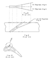
- FIGS. 14 and 15 show a second embodiment of the film cooling hole in which the film hole is a compound angled film hole.
- FIG. 12 shows a top view of the film hole with the same basic shape as in the FIG. 12 film hole except the film hole is angled with respect to the hot gas flow path over the film hole.
- the left side wall has a 0 to 5 degree expansion while the right side wall has a radius of curvature of R 3 .
- Two outer ribs form three inlets to the diffusion section of the film hole, and two inner ribs of shorter length form three separate diffusion paths inside of the two outer ribs.
- the total angle of the film hole outlet is from 20 to 30 degrees which is the compound angle of the film hole.
- FIG. 13 shows a cross section side view of the film hole with the metering inlet section of constant diameter area followed by the diffusion section that has a downstream wall with a radius of curvature of R 2 and an outlet angle of 1.5 to 25 degrees.
- each individual inner wall of the film cooling hole is constructed with various radiuses of curvatures independent of each other. This unique film cooling hole construction will allow radial diffusion of the stream-wise oriented flow, combining the best aspects of both radial and stream-wise straight holes.
- the straight wall at the upstream side of the film cooling hole has an infinite radius (straight) of curvature while the downstream side wall has a positive radius of curvature, which creates diffusion in the stream-wise flow direction.
- the straight wall in the upstream flow direction has a built-in tapered flow guide that eliminates the hot gas entrainment problem of the prior art.
- the end product from the tapered flow guide in the upstream corner yields a diffusion film cooling hole at a much lower cooling injection angle.
- the curved surfaces on the downstream wall are formed with a continuous arc connecting the point at the end of the metering section and the intersection between the expansion surfaces to the airfoil external wall.
- the radius of curvature for the lower surface is determined with the continuous arc tangent to the points A and cut through points B.
- the downstream surface for the film hole has an expansion of between 15 to 25 degrees toward the airfoil trailing edge.
- the position of the exit flow guides is dependent on the film flow distribution requirement. It can be positioned at equal inlet area to obtain the same amount of film flow or one can position the flow guide at the large flow area for the corner channel than the middle channels. This allows for a higher film flow in the corner channels for the elimination of vortices formation underneath the film injection location.
- the radial outward and radial inward film cooling hole walls can be curved at the same radius of curvature. This increases the film cooling hole breakout and yields a better film coverage in the spanwise direction.
- This film cooling hole expansion between 15 to 25 degrees, is valid only if the hole is oriented in the stream-wise direction or at a small compound angle at less than 20 degrees.
- the cooling hole is used in a highly radial direction oriented application (greater than 40 degrees from the axial flow direction) then the radial outward surface for the film cooling hole has to be at a different radius of curvature than the radial inward surface.
- the radial outward surface will be at an expansion of less than 7 degrees.
- the radius of curvature for the inward wall can be much smaller than the outward surface and the expansion angle will from 20 to 30 degrees which is larger than the 15 to 25 degree expansion used for the stream-wise angled film hole.
- FIG. 12 shows details of the compound angled curved film cooling hole. The end product of this differential yields a stream-wise oriented cooling flow injection flow phenomena for a compound angled film cooling hole with a much larger film coverage.
Abstract
Description
Claims (16)
Priority Applications (1)
| Application Number | Priority Date | Filing Date | Title |
|---|---|---|---|
| US12/273,443 US7997868B1 (en) | 2008-11-18 | 2008-11-18 | Film cooling hole for turbine airfoil |
Applications Claiming Priority (1)
| Application Number | Priority Date | Filing Date | Title |
|---|---|---|---|
| US12/273,443 US7997868B1 (en) | 2008-11-18 | 2008-11-18 | Film cooling hole for turbine airfoil |
Publications (1)
| Publication Number | Publication Date |
|---|---|
| US7997868B1 true US7997868B1 (en) | 2011-08-16 |
Family
ID=44358498
Family Applications (1)
| Application Number | Title | Priority Date | Filing Date |
|---|---|---|---|
| US12/273,443 Expired - Fee Related US7997868B1 (en) | 2008-11-18 | 2008-11-18 | Film cooling hole for turbine airfoil |
Country Status (1)
| Country | Link |
|---|---|
| US (1) | US7997868B1 (en) |
Cited By (167)
| Publication number | Priority date | Publication date | Assignee | Title |
|---|---|---|---|---|
| US20100068068A1 (en) * | 2008-09-16 | 2010-03-18 | Siemens Energy, Inc. | Turbine Airfoil Cooling System with Diffusion Film Cooling Hole Having Flow Restriction Rib |
| US20100329846A1 (en) * | 2009-06-24 | 2010-12-30 | Honeywell International Inc. | Turbine engine components |
| CN102052092A (en) * | 2009-10-28 | 2011-05-11 | 通用电气公司 | Method and structure for cooling airfoil surfaces using asymmetric chevron film holes |
| US20110123312A1 (en) * | 2009-11-25 | 2011-05-26 | Honeywell International Inc. | Gas turbine engine components with improved film cooling |
| US20120051941A1 (en) * | 2010-08-31 | 2012-03-01 | General Electric Company | Components with conformal curved film holes and methods of manufacture |
| CN103104300A (en) * | 2011-11-09 | 2013-05-15 | 通用电气公司 | Film hole trench |
| US20130206733A1 (en) * | 2012-02-15 | 2013-08-15 | United Technologies Corporation | Edm method for multi-lobed cooling hole |
| WO2013123121A1 (en) | 2012-02-15 | 2013-08-22 | United Technologies Corporation | Gas turbine engine component with multi-lobed cooling hole |
| WO2013122910A1 (en) * | 2012-02-15 | 2013-08-22 | United Technologies Corporation | Multi-lobed cooling hole |
| WO2013123120A1 (en) * | 2012-02-15 | 2013-08-22 | United Technologies Corporation | Gas turbine engine component with impingement and lobed cooling hole |
| WO2013123012A1 (en) * | 2012-02-15 | 2013-08-22 | United Technologies Corporation | Gas turbine engine component with compound cusp cooling configuration |
| US8522558B1 (en) | 2012-02-15 | 2013-09-03 | United Technologies Corporation | Multi-lobed cooling hole array |
| US8572983B2 (en) | 2012-02-15 | 2013-11-05 | United Technologies Corporation | Gas turbine engine component with impingement and diffusive cooling |
| WO2013165507A2 (en) | 2012-02-15 | 2013-11-07 | United Technologies Corporation | Cooling hole with asymmetric diffuser |
| US8584470B2 (en) | 2012-02-15 | 2013-11-19 | United Technologies Corporation | Tri-lobed cooling hole and method of manufacture |
| WO2013165517A3 (en) * | 2012-02-15 | 2013-12-19 | United Technologies Corporation | Gas turbine engine component with diffusive cooling hole |
| WO2013165518A3 (en) * | 2012-02-15 | 2013-12-19 | United Technologies Corporation | Gas turbine engine component with cusped, lobed cooling hole |
| EP2666964A3 (en) * | 2012-05-22 | 2014-01-01 | Honeywell International, Inc. | Gas turbine engine blades with cooling hole trenches |
| WO2013165510A3 (en) * | 2012-02-15 | 2014-01-09 | United Technologies Corporation | Multi-lobed cooling hole and method of manufacture |
| US8628293B2 (en) | 2010-06-17 | 2014-01-14 | Honeywell International Inc. | Gas turbine engine components with cooling hole trenches |
| US8689568B2 (en) | 2012-02-15 | 2014-04-08 | United Technologies Corporation | Cooling hole with thermo-mechanical fatigue resistance |
| US8707713B2 (en) | 2012-02-15 | 2014-04-29 | United Technologies Corporation | Cooling hole with crenellation features |
| WO2014105393A1 (en) * | 2012-12-28 | 2014-07-03 | United Technologies Corporation | Non-line of sight electro discharge machined part |
| US20140271229A1 (en) * | 2011-12-15 | 2014-09-18 | Ihi Corporation | Turbine blade |
| WO2014150490A1 (en) * | 2013-03-15 | 2014-09-25 | United Technologies Corporation | Additive manufacturing method for the addition of features within cooling holes |
| US8850828B2 (en) | 2012-02-15 | 2014-10-07 | United Technologies Corporation | Cooling hole with curved metering section |
| EP2716866A3 (en) * | 2012-10-04 | 2014-10-29 | Honeywell International Inc. | Gas turbine engine components with lateral and forward sweep film cooling holes |
| WO2014197043A2 (en) | 2013-03-15 | 2014-12-11 | United Technologies Corporation | Multi-lobed cooling hole |
| WO2014186006A3 (en) * | 2013-02-15 | 2015-02-26 | United Technologies Corporation | Cooling hole for a gas turbine engine component |
| EP2815108A4 (en) * | 2012-02-15 | 2016-01-06 | United Technologies Corp | Multi-lobed cooling hole |
| US9279330B2 (en) | 2012-02-15 | 2016-03-08 | United Technologies Corporation | Gas turbine engine component with converging/diverging cooling passage |
| US9284844B2 (en) | 2012-02-15 | 2016-03-15 | United Technologies Corporation | Gas turbine engine component with cusped cooling hole |
| US20160090843A1 (en) * | 2014-09-30 | 2016-03-31 | General Electric Company | Turbine components with stepped apertures |
| EP3009599A1 (en) * | 2014-10-17 | 2016-04-20 | United Technologies Corporation | Gas turbine engine component with film cooling hole feature |
| US9416665B2 (en) | 2012-02-15 | 2016-08-16 | United Technologies Corporation | Cooling hole with enhanced flow attachment |
| US9416971B2 (en) | 2012-02-15 | 2016-08-16 | United Technologies Corporation | Multiple diffusing cooling hole |
| US20160245092A1 (en) * | 2013-12-20 | 2016-08-25 | Rolls-Royce Corporation | Machined film holes |
| US9441488B1 (en) | 2013-11-07 | 2016-09-13 | United States Of America As Represented By The Secretary Of The Air Force | Film cooling holes for gas turbine airfoils |
| US20170003026A1 (en) * | 2015-06-30 | 2017-01-05 | Rolls-Royce Corporation | Combustor tile |
| US9598979B2 (en) | 2012-02-15 | 2017-03-21 | United Technologies Corporation | Manufacturing methods for multi-lobed cooling holes |
| US9644903B1 (en) | 2012-06-01 | 2017-05-09 | The United States Of America As Represented By The Administrator Of National Aeronautics And Space Administration | Shaped recess flow control |
| US9650900B2 (en) | 2012-05-07 | 2017-05-16 | Honeywell International Inc. | Gas turbine engine components with film cooling holes having cylindrical to multi-lobe configurations |
| US9695751B2 (en) | 2012-01-31 | 2017-07-04 | United Technologies Corporation | Geared turbofan gas turbine engine architecture |
| US9726019B2 (en) | 2012-09-28 | 2017-08-08 | United Technologies Corporation | Low noise compressor rotor for geared turbofan engine |
| US9739206B2 (en) | 2012-01-31 | 2017-08-22 | United Technologies Corporation | Geared turbofan gas turbine engine architecture |
| US9752511B2 (en) | 2011-06-08 | 2017-09-05 | United Technologies Corporation | Geared architecture for high speed and small volume fan drive turbine |
| US9765968B2 (en) | 2013-01-23 | 2017-09-19 | Honeywell International Inc. | Combustors with complex shaped effusion holes |
| US9771893B2 (en) | 2007-08-23 | 2017-09-26 | United Technologies Corporation | Gas turbine engine with axial movable fan variable area nozzle |
| US9777580B2 (en) | 2014-02-19 | 2017-10-03 | United Technologies Corporation | Gas turbine engine airfoil |
| US9816443B2 (en) | 2012-09-27 | 2017-11-14 | United Technologies Corporation | Method for setting a gear ratio of a fan drive gear system of a gas turbine engine |
| US9835052B2 (en) | 2012-01-31 | 2017-12-05 | United Technologies Corporation | Gas turbine engine with high speed low pressure turbine section and bearing support features |
| US9840969B2 (en) | 2012-05-31 | 2017-12-12 | United Technologies Corporation | Gear system architecture for gas turbine engine |
| US9879608B2 (en) | 2014-03-17 | 2018-01-30 | United Technologies Corporation | Oil loss protection for a fan drive gear system |
| US20180051570A1 (en) * | 2016-08-22 | 2018-02-22 | Doosan Heavy Industries & Construction Co., Ltd. | Gas turbine blade |
| US9926885B2 (en) | 2011-07-05 | 2018-03-27 | United Technologies Corporation | Efficient, low pressure ratio propulsor for gas turbine engines |
| US9951860B2 (en) | 2006-08-15 | 2018-04-24 | United Technologies Corporation | Ring gear mounting arrangement with oil scavenge scheme |
| US10047699B2 (en) | 2013-03-15 | 2018-08-14 | United Technologies Corporation | Thrust efficient turbofan engine |
| US10060357B2 (en) | 2007-08-01 | 2018-08-28 | United Technologies Corporation | Turbine section of high bypass turbofan |
| US10082105B2 (en) | 2006-08-15 | 2018-09-25 | United Technologies Corporation | Gas turbine engine with geared architecture |
| US10196989B2 (en) | 2006-08-15 | 2019-02-05 | United Technologies Corporation | Gas turbine engine gear train |
| US10227893B2 (en) | 2011-06-08 | 2019-03-12 | United Technologies Corporation | Flexible support structure for a geared architecture gas turbine engine |
| US10233773B2 (en) | 2015-11-17 | 2019-03-19 | United Technologies Corporation | Monitoring system for non-ferrous metal particles |
| US10240526B2 (en) | 2012-01-31 | 2019-03-26 | United Technologies Corporation | Gas turbine engine with high speed low pressure turbine section |
| US10287914B2 (en) | 2012-01-31 | 2019-05-14 | United Technologies Corporation | Gas turbine engine with high speed low pressure turbine section and bearing support features |
| US10301971B2 (en) | 2012-12-20 | 2019-05-28 | United Technologies Corporation | Low pressure ratio fan engine having a dimensional relationship between inlet and fan size |
| US10309239B2 (en) | 2013-02-15 | 2019-06-04 | United Technologies Corporation | Cooling hole for a gas turbine engine component |
| US10309414B2 (en) | 2014-02-19 | 2019-06-04 | United Technologies Corporation | Gas turbine engine airfoil |
| US20190210132A1 (en) * | 2018-01-05 | 2019-07-11 | General Electric Company | Method of forming cooling passage for turbine component with cap element |
| US10358924B2 (en) | 2015-03-18 | 2019-07-23 | United Technologies Corporation | Turbofan arrangement with blade channel variations |
| US10422230B2 (en) | 2012-02-15 | 2019-09-24 | United Technologies Corporation | Cooling hole with curved metering section |
| US10436116B2 (en) | 2012-03-30 | 2019-10-08 | United Technologies Corporation | Gas turbine engine geared architecture axial retention arrangement |
| US10443401B2 (en) | 2016-09-02 | 2019-10-15 | United Technologies Corporation | Cooled turbine vane with alternately orientated film cooling hole rows |
| US10443396B2 (en) | 2016-06-13 | 2019-10-15 | General Electric Company | Turbine component cooling holes |
| US10451004B2 (en) | 2008-06-02 | 2019-10-22 | United Technologies Corporation | Gas turbine engine with low stage count low pressure turbine |
| US10465549B2 (en) | 2012-01-10 | 2019-11-05 | United Technologies Corporation | Gas turbine engine forward bearing compartment architecture |
| US10544741B2 (en) | 2007-03-05 | 2020-01-28 | United Technologies Corporation | Flutter sensing and control system for a gas turbine engine |
| US10550852B2 (en) | 2014-02-19 | 2020-02-04 | United Technologies Corporation | Gas turbine engine airfoil |
| US10563576B2 (en) | 2013-03-15 | 2020-02-18 | United Technologies Corporation | Turbofan engine bearing and gearbox arrangement |
| US10577965B2 (en) | 2006-08-15 | 2020-03-03 | United Technologies Corporation | Epicyclic gear train |
| US10578053B2 (en) | 2012-01-31 | 2020-03-03 | United Technologies Corporation | Gas turbine engine variable area fan nozzle with ice management |
| US10578018B2 (en) | 2013-11-22 | 2020-03-03 | United Technologies Corporation | Geared turbofan engine gearbox arrangement |
| US10584660B2 (en) | 2012-01-24 | 2020-03-10 | United Technologies Corporation | Geared turbomachine fan and compressor rotation |
| US10605167B2 (en) | 2011-04-15 | 2020-03-31 | United Technologies Corporation | Gas turbine engine front center body architecture |
| US10605351B2 (en) | 2006-07-05 | 2020-03-31 | United Technologies Corporation | Oil baffle for gas turbine fan drive gear system |
| US10605092B2 (en) | 2016-07-11 | 2020-03-31 | United Technologies Corporation | Cooling hole with shaped meter |
| US10655538B2 (en) | 2012-02-29 | 2020-05-19 | United Technologies Corporation | Geared gas turbine engine with reduced fan noise |
| US10677192B2 (en) | 2006-10-12 | 2020-06-09 | Raytheon Technologies Corporation | Dual function cascade integrated variable area fan nozzle and thrust reverser |
| US10731563B2 (en) | 2012-01-31 | 2020-08-04 | Raytheon Technologies Corporation | Compressed air bleed supply for buffer system |
| US10731559B2 (en) | 2015-04-27 | 2020-08-04 | Raytheon Technologies Corporation | Lubrication system for gas turbine engines |
| US10753285B2 (en) | 2006-07-05 | 2020-08-25 | Raytheon Technologies Corporation | Method of assembly for gas turbine fan drive gear system |
| US10781755B2 (en) | 2012-01-31 | 2020-09-22 | Raytheon Technologies Corporation | Turbine engine gearbox |
| US10794292B2 (en) | 2012-01-31 | 2020-10-06 | United Technologies Corporation | Geared turbofan gas turbine engine architecture |
| US10801355B2 (en) | 2015-12-01 | 2020-10-13 | Raytheon Technologies Corporation | Geared turbofan with four star/planetary gear reduction |
| US10808617B2 (en) | 2012-09-28 | 2020-10-20 | Raytheon Technologies Corporation | Split-zone flow metering T-tube |
| US10815888B2 (en) | 2011-07-29 | 2020-10-27 | Raytheon Technologies Corporation | Geared turbofan bearing arrangement |
| US10823052B2 (en) | 2013-10-16 | 2020-11-03 | Raytheon Technologies Corporation | Geared turbofan engine with targeted modular efficiency |
| US10830053B2 (en) * | 2017-11-20 | 2020-11-10 | General Electric Company | Engine component cooling hole |
| US10830178B2 (en) | 2012-01-31 | 2020-11-10 | Raytheon Technologies Corporation | Gas turbine engine variable area fan nozzle control |
| US10830153B2 (en) | 2012-04-02 | 2020-11-10 | Raytheon Technologies Corporation | Geared turbofan engine with power density range |
| US10830152B2 (en) | 2007-09-21 | 2020-11-10 | Raytheon Technologies Corporation | Gas turbine engine compressor arrangement |
| US10890195B2 (en) | 2014-02-19 | 2021-01-12 | Raytheon Technologies Corporation | Gas turbine engine airfoil |
| US10907482B2 (en) | 2012-01-31 | 2021-02-02 | Raytheon Technologies Corporation | Turbine blade damper seal |
| US10914315B2 (en) | 2014-02-19 | 2021-02-09 | Raytheon Technologies Corporation | Gas turbine engine airfoil |
| CN112627904A (en) * | 2020-12-23 | 2021-04-09 | 西北工业大学 | Novel bucket type air film cooling hole and design method thereof |
| US10989143B2 (en) | 2009-03-17 | 2021-04-27 | Raytheon Technologies Corporation | Gas turbine engine bifurcation located fan variable area nozzle |
| US11008947B2 (en) | 2014-03-07 | 2021-05-18 | Raytheon Technologies Corporation | Geared turbofan with integral front support and carrier |
| US11015550B2 (en) | 2012-12-20 | 2021-05-25 | Raytheon Technologies Corporation | Low pressure ratio fan engine having a dimensional relationship between inlet and fan size |
| US11021965B2 (en) | 2016-05-19 | 2021-06-01 | Honeywell International Inc. | Engine components with cooling holes having tailored metering and diffuser portions |
| US11041507B2 (en) | 2014-02-19 | 2021-06-22 | Raytheon Technologies Corporation | Gas turbine engine airfoil |
| US11053843B2 (en) | 2012-04-02 | 2021-07-06 | Raytheon Technologies Corporation | Geared turbofan engine with a high ratio of thrust to turbine volume |
| US11053816B2 (en) | 2013-05-09 | 2021-07-06 | Raytheon Technologies Corporation | Turbofan engine front section |
| US11053811B2 (en) | 2015-06-23 | 2021-07-06 | Raytheon Technologies Corporation | Roller bearings for high ratio geared turbofan engine |
| US11066954B2 (en) | 2014-07-29 | 2021-07-20 | Raytheon Technologies Corporation | Geared gas turbine engine with oil deaerator and air removal |
| US11073157B2 (en) | 2011-07-05 | 2021-07-27 | Raytheon Technologies Corporation | Efficient, low pressure ratio propulsor for gas turbine engines |
| US11085400B2 (en) | 2015-02-06 | 2021-08-10 | Raytheon Technologies Corporation | Propulsion system arrangement for turbofan gas turbine engine |
| US11085641B2 (en) | 2018-11-27 | 2021-08-10 | Honeywell International Inc. | Plug resistant effusion holes for gas turbine engine |
| US11098644B2 (en) | 2012-01-31 | 2021-08-24 | Raytheon Technologies Corporation | Gas turbine engine buffer system |
| US11125167B2 (en) | 2012-05-31 | 2021-09-21 | Raytheon Technologies Corporation | Fundamental gear system architecture |
| US11125155B2 (en) | 2013-11-01 | 2021-09-21 | Raytheon Technologies Corporation | Geared turbofan arrangement with core split power ratio |
| US11136920B2 (en) | 2013-03-12 | 2021-10-05 | Raytheon Technologies Corporation | Flexible coupling for geared turbine engine |
| US11143109B2 (en) | 2013-03-14 | 2021-10-12 | Raytheon Technologies Corporation | Low noise turbine for geared gas turbine engine |
| US11149689B2 (en) | 2012-01-31 | 2021-10-19 | Raytheon Technologies Corporation | Gas turbine engine shaft bearing configuration |
| US11149650B2 (en) | 2007-08-01 | 2021-10-19 | Raytheon Technologies Corporation | Turbine section of high bypass turbofan |
| US11174936B2 (en) | 2011-06-08 | 2021-11-16 | Raytheon Technologies Corporation | Flexible support structure for a geared architecture gas turbine engine |
| US11181074B2 (en) | 2012-01-31 | 2021-11-23 | Raytheon Technologies Corporation | Variable area fan nozzle with wall thickness distribution |
| US11187160B2 (en) | 2017-01-03 | 2021-11-30 | Raytheon Technologies Corporation | Geared turbofan with non-epicyclic gear reduction system |
| US11193496B2 (en) | 2014-02-19 | 2021-12-07 | Raytheon Technologies Corporation | Gas turbine engine airfoil |
| US11193497B2 (en) | 2014-02-19 | 2021-12-07 | Raytheon Technologies Corporation | Gas turbine engine airfoil |
| US11209013B2 (en) | 2014-02-19 | 2021-12-28 | Raytheon Technologies Corporation | Gas turbine engine airfoil |
| US11215143B2 (en) | 2013-11-01 | 2022-01-04 | Raytheon Technologies Corporation | Geared turbofan arrangement with core split power ratio |
| US11236679B2 (en) | 2012-10-08 | 2022-02-01 | Raytheon Technologies Corporation | Geared turbine engine with relatively lightweight propulsor module |
| US11242805B2 (en) | 2007-08-01 | 2022-02-08 | Raytheon Technologies Corporation | Turbine section of high bypass turbofan |
| US11286852B2 (en) | 2012-01-31 | 2022-03-29 | Raytheon Technologies Corporation | Gas turbine engine buffer system |
| US11300141B2 (en) | 2015-04-07 | 2022-04-12 | Raytheon Technologies Corporation | Modal noise reduction for gas turbine engine |
| US11339667B2 (en) | 2020-08-11 | 2022-05-24 | Raytheon Technologies Corporation | Cooling arrangement including overlapping diffusers |
| US11346289B2 (en) | 2007-08-01 | 2022-05-31 | Raytheon Technologies Corporation | Turbine section of high bypass turbofan |
| US11352888B2 (en) * | 2018-08-10 | 2022-06-07 | Ningbo Institute Of Materials Technology & Engineering, Chinese Academy Of Sciences | Turbine blade having gas film cooling structure with a composite irregular groove and a method of manufacturing the same |
| US11384657B2 (en) | 2017-06-12 | 2022-07-12 | Raytheon Technologies Corporation | Geared gas turbine engine with gear driving low pressure compressor and fan at a common speed and a shear section to provide overspeed protection |
| US11391294B2 (en) | 2014-02-19 | 2022-07-19 | Raytheon Technologies Corporation | Gas turbine engine airfoil |
| US11391216B2 (en) | 2013-02-06 | 2022-07-19 | Raytheon Technologies Corporation | Elongated geared turbofan with high bypass ratio |
| US11408436B2 (en) | 2014-02-19 | 2022-08-09 | Raytheon Technologies Corporation | Gas turbine engine airfoil |
| US11408372B2 (en) | 2007-08-28 | 2022-08-09 | Raytheon Technologies Corporation | Gas turbine engine front architecture |
| US11459898B2 (en) * | 2020-07-19 | 2022-10-04 | Raytheon Technologies Corporation | Airfoil cooling holes |
| US11486269B2 (en) | 2012-01-31 | 2022-11-01 | Raytheon Technologies Corporation | Gas turbine engine shaft bearing configuration |
| US11486311B2 (en) | 2007-08-01 | 2022-11-01 | Raytheon Technologies Corporation | Turbine section of high bypass turbofan |
| US11499476B2 (en) | 2012-01-31 | 2022-11-15 | Raytheon Technologies Corporation | Gas turbine engine buffer system |
| US11536204B2 (en) | 2018-01-03 | 2022-12-27 | Raytheon Technologies Corporation | Method of assembly for gear system with rotating carrier |
| US20220412217A1 (en) * | 2021-06-24 | 2022-12-29 | Doosan Enerbility Co., Ltd. | Turbine blade and turbine including the same |
| US11542831B1 (en) | 2021-08-13 | 2023-01-03 | Raytheon Technologies Corporation | Energy beam positioning during formation of a cooling aperture |
| US11585276B2 (en) | 2012-01-31 | 2023-02-21 | Raytheon Technologies Corporation | Gas turbine engine with high speed low pressure turbine section and bearing support features |
| US11603769B2 (en) | 2021-08-13 | 2023-03-14 | Raytheon Technologies Corporation | Forming lined cooling aperture(s) in a turbine engine component |
| US11673200B2 (en) | 2021-08-13 | 2023-06-13 | Raytheon Technologies Corporation | Forming cooling aperture(s) using electrical discharge machining |
| US11719245B2 (en) | 2021-07-19 | 2023-08-08 | Raytheon Technologies Corporation | Compressor arrangement for a gas turbine engine |
| US11719161B2 (en) | 2013-03-14 | 2023-08-08 | Raytheon Technologies Corporation | Low noise turbine for geared gas turbine engine |
| US11725589B2 (en) | 2014-07-01 | 2023-08-15 | Raytheon Technologies Corporation | Geared gas turbine engine with oil deaerator |
| US11725670B2 (en) | 2012-01-31 | 2023-08-15 | Raytheon Technologies Corporation | Compressor flowpath |
| US11732590B2 (en) | 2021-08-13 | 2023-08-22 | Raytheon Technologies Corporation | Transition section for accommodating mismatch between other sections of a cooling aperture in a turbine engine component |
| US11754000B2 (en) | 2021-07-19 | 2023-09-12 | Rtx Corporation | High and low spool configuration for a gas turbine engine |
| US11753951B2 (en) | 2018-10-18 | 2023-09-12 | Rtx Corporation | Rotor assembly for gas turbine engines |
| US11781506B2 (en) | 2020-06-03 | 2023-10-10 | Rtx Corporation | Splitter and guide vane arrangement for gas turbine engines |
| US11781490B2 (en) | 2012-10-09 | 2023-10-10 | Rtx Corporation | Operability geared turbofan engine including compressor section variable guide vanes |
| US11813706B2 (en) | 2021-08-13 | 2023-11-14 | Rtx Corporation | Methods for forming cooling apertures in a turbine engine component |
| US11814968B2 (en) | 2021-07-19 | 2023-11-14 | Rtx Corporation | Gas turbine engine with idle thrust ratio |
| US11815001B2 (en) | 2010-10-12 | 2023-11-14 | Rtx Corporation | Planetary gear system arrangement with auxiliary oil system |
| US11898465B2 (en) | 2021-08-13 | 2024-02-13 | Rtx Corporation | Forming lined cooling aperture(s) in a turbine engine component |
| US11913119B2 (en) | 2021-08-13 | 2024-02-27 | Rtx Corporation | Forming cooling aperture(s) in a turbine engine component |
| US11971052B1 (en) | 2023-08-02 | 2024-04-30 | Rtx Corporation | Modal noise reduction for gas turbine engine |
Citations (3)
| Publication number | Priority date | Publication date | Assignee | Title |
|---|---|---|---|---|
| US4684323A (en) * | 1985-12-23 | 1987-08-04 | United Technologies Corporation | Film cooling passages with curved corners |
| US7300242B2 (en) * | 2005-12-02 | 2007-11-27 | Siemens Power Generation, Inc. | Turbine airfoil with integral cooling system |
| US7374401B2 (en) * | 2005-03-01 | 2008-05-20 | General Electric Company | Bell-shaped fan cooling holes for turbine airfoil |
-
2008
- 2008-11-18 US US12/273,443 patent/US7997868B1/en not_active Expired - Fee Related
Patent Citations (3)
| Publication number | Priority date | Publication date | Assignee | Title |
|---|---|---|---|---|
| US4684323A (en) * | 1985-12-23 | 1987-08-04 | United Technologies Corporation | Film cooling passages with curved corners |
| US7374401B2 (en) * | 2005-03-01 | 2008-05-20 | General Electric Company | Bell-shaped fan cooling holes for turbine airfoil |
| US7300242B2 (en) * | 2005-12-02 | 2007-11-27 | Siemens Power Generation, Inc. | Turbine airfoil with integral cooling system |
Cited By (323)
| Publication number | Priority date | Publication date | Assignee | Title |
|---|---|---|---|---|
| US10605351B2 (en) | 2006-07-05 | 2020-03-31 | United Technologies Corporation | Oil baffle for gas turbine fan drive gear system |
| US11448310B2 (en) | 2006-07-05 | 2022-09-20 | Raytheon Technologies Corporation | Oil baffle for gas turbine fan drive gear system |
| US11079007B2 (en) | 2006-07-05 | 2021-08-03 | Raytheon Technologies Corporation | Oil baffle for gas turbine fan drive gear system |
| US11773787B2 (en) | 2006-07-05 | 2023-10-03 | Rtx Corporation | Method of assembly for gas turbine fan drive gear system |
| US11339726B2 (en) | 2006-07-05 | 2022-05-24 | Raytheon Technologies Corporation | Method of assembly for gas turbine fan drive gear system |
| US10753285B2 (en) | 2006-07-05 | 2020-08-25 | Raytheon Technologies Corporation | Method of assembly for gas turbine fan drive gear system |
| US11221066B2 (en) | 2006-08-15 | 2022-01-11 | Raytheon Technologies Corporation | Ring gear mounting arrangement with oil scavenge scheme |
| US11499624B2 (en) | 2006-08-15 | 2022-11-15 | Raytheon Technologies Corporation | Ring gear mounting arrangement with oil scavenge scheme |
| US10830334B2 (en) | 2006-08-15 | 2020-11-10 | Raytheon Technologies Corporation | Ring gear mounting arrangement with oil scavenge scheme |
| US11319831B2 (en) | 2006-08-15 | 2022-05-03 | Raytheon Technologies Corporation | Epicyclic gear train |
| US9951860B2 (en) | 2006-08-15 | 2018-04-24 | United Technologies Corporation | Ring gear mounting arrangement with oil scavenge scheme |
| US10082105B2 (en) | 2006-08-15 | 2018-09-25 | United Technologies Corporation | Gas turbine engine with geared architecture |
| US10890245B2 (en) | 2006-08-15 | 2021-01-12 | Raytheon Technologies Corporation | Epicyclic gear train |
| US11378039B2 (en) | 2006-08-15 | 2022-07-05 | Raytheon Technologies Corporation | Ring gear mounting arrangement with oil scavenge scheme |
| US10907579B2 (en) | 2006-08-15 | 2021-02-02 | Raytheon Technologies Corporation | Gas turbine engine with geared architecture |
| US10527151B1 (en) | 2006-08-15 | 2020-01-07 | United Technologies Corporation | Gas turbine engine with geared architecture |
| US10125858B2 (en) | 2006-08-15 | 2018-11-13 | United Technologies Corporation | Ring gear mounting arrangement with oil scavenge scheme |
| US10570855B2 (en) | 2006-08-15 | 2020-02-25 | United Technologies Corporation | Gas turbine engine with geared architecture |
| US11680492B2 (en) | 2006-08-15 | 2023-06-20 | Raytheon Technologies Corporation | Epicyclic gear train |
| US10577965B2 (en) | 2006-08-15 | 2020-03-03 | United Technologies Corporation | Epicyclic gear train |
| US10196989B2 (en) | 2006-08-15 | 2019-02-05 | United Technologies Corporation | Gas turbine engine gear train |
| US10591047B2 (en) | 2006-08-15 | 2020-03-17 | United Technologies Corporation | Ring gear mounting arrangement with oil scavenge scheme |
| US11499502B2 (en) | 2006-10-12 | 2022-11-15 | Raytheon Technologies Corporation | Dual function cascade integrated variable area fan nozzle and thrust reverser |
| US10677192B2 (en) | 2006-10-12 | 2020-06-09 | Raytheon Technologies Corporation | Dual function cascade integrated variable area fan nozzle and thrust reverser |
| US10711703B2 (en) | 2007-03-05 | 2020-07-14 | Raytheon Technologies Corporation | Flutter sensing and control system for a gas turbine engine |
| US11396847B2 (en) | 2007-03-05 | 2022-07-26 | Raytheon Technologies Corporation | Flutter sensing and control system for a gas turbine engine |
| US10544741B2 (en) | 2007-03-05 | 2020-01-28 | United Technologies Corporation | Flutter sensing and control system for a gas turbine engine |
| US10697375B2 (en) | 2007-03-05 | 2020-06-30 | Raytheon Technologies Corporation | Flutter sensing and control system for a gas turbine engine |
| US11242805B2 (en) | 2007-08-01 | 2022-02-08 | Raytheon Technologies Corporation | Turbine section of high bypass turbofan |
| US11346289B2 (en) | 2007-08-01 | 2022-05-31 | Raytheon Technologies Corporation | Turbine section of high bypass turbofan |
| US11614036B2 (en) | 2007-08-01 | 2023-03-28 | Raytheon Technologies Corporation | Turbine section of gas turbine engine |
| US10060357B2 (en) | 2007-08-01 | 2018-08-28 | United Technologies Corporation | Turbine section of high bypass turbofan |
| US11215123B2 (en) | 2007-08-01 | 2022-01-04 | Raytheon Technologies Corporation | Turbine section of high bypass turbofan |
| US10371061B2 (en) | 2007-08-01 | 2019-08-06 | United Technologies Corporation | Turbine section of high bypass turbofan |
| US11486311B2 (en) | 2007-08-01 | 2022-11-01 | Raytheon Technologies Corporation | Turbine section of high bypass turbofan |
| US11149650B2 (en) | 2007-08-01 | 2021-10-19 | Raytheon Technologies Corporation | Turbine section of high bypass turbofan |
| US11480108B2 (en) | 2007-08-01 | 2022-10-25 | Raytheon Technologies Corporation | Turbine section of high bypass turbofan |
| US10794293B2 (en) | 2007-08-01 | 2020-10-06 | Raytheon Technologies Corporation | Turbine section of high bypass turbofan |
| US10174716B2 (en) | 2007-08-23 | 2019-01-08 | United Technologies Corporation | Gas turbine engine with axial movable fan variable area nozzle |
| US10087885B2 (en) | 2007-08-23 | 2018-10-02 | United Technologies Corporation | Gas turbine engine with axial movable fan variable area nozzle |
| US11162456B2 (en) | 2007-08-23 | 2021-11-02 | Raytheon Technologies Corporation | Gas turbine engine with axial movable fan variable area nozzle |
| US11454193B2 (en) | 2007-08-23 | 2022-09-27 | Raytheon Technologies Corporation | Gas turbine engine with axial movable fan variable area nozzle |
| US9784212B2 (en) | 2007-08-23 | 2017-10-10 | United Technologies Corporation | Gas turbine engine with axial movable fan variable area nozzle |
| US10174715B2 (en) | 2007-08-23 | 2019-01-08 | United Technologies Corporation | Gas turbine engine with axial movable fan variable area nozzle |
| US9771893B2 (en) | 2007-08-23 | 2017-09-26 | United Technologies Corporation | Gas turbine engine with axial movable fan variable area nozzle |
| US9822732B2 (en) | 2007-08-23 | 2017-11-21 | United Technologies Corporation | Gas turbine engine with axial movable fan variable area nozzle |
| US11408372B2 (en) | 2007-08-28 | 2022-08-09 | Raytheon Technologies Corporation | Gas turbine engine front architecture |
| US11846238B2 (en) | 2007-09-21 | 2023-12-19 | Rtx Corporation | Gas turbine engine compressor arrangement |
| US10830152B2 (en) | 2007-09-21 | 2020-11-10 | Raytheon Technologies Corporation | Gas turbine engine compressor arrangement |
| US11731773B2 (en) | 2008-06-02 | 2023-08-22 | Raytheon Technologies Corporation | Engine mount system for a gas turbine engine |
| US11286883B2 (en) | 2008-06-02 | 2022-03-29 | Raytheon Technologies Corporation | Gas turbine engine with low stage count low pressure turbine and engine mounting arrangement |
| US10451004B2 (en) | 2008-06-02 | 2019-10-22 | United Technologies Corporation | Gas turbine engine with low stage count low pressure turbine |
| US20100068068A1 (en) * | 2008-09-16 | 2010-03-18 | Siemens Energy, Inc. | Turbine Airfoil Cooling System with Diffusion Film Cooling Hole Having Flow Restriction Rib |
| US8092177B2 (en) * | 2008-09-16 | 2012-01-10 | Siemens Energy, Inc. | Turbine airfoil cooling system with diffusion film cooling hole having flow restriction rib |
| US11391240B2 (en) | 2009-03-17 | 2022-07-19 | Raytheon Technologies Corporation | Gas turbine engine bifurcation located fan variable area nozzle |
| US10989143B2 (en) | 2009-03-17 | 2021-04-27 | Raytheon Technologies Corporation | Gas turbine engine bifurcation located fan variable area nozzle |
| US20100329846A1 (en) * | 2009-06-24 | 2010-12-30 | Honeywell International Inc. | Turbine engine components |
| US8371814B2 (en) | 2009-06-24 | 2013-02-12 | Honeywell International Inc. | Turbine engine components |
| CN102052092A (en) * | 2009-10-28 | 2011-05-11 | 通用电气公司 | Method and structure for cooling airfoil surfaces using asymmetric chevron film holes |
| US8529193B2 (en) | 2009-11-25 | 2013-09-10 | Honeywell International Inc. | Gas turbine engine components with improved film cooling |
| US20110123312A1 (en) * | 2009-11-25 | 2011-05-26 | Honeywell International Inc. | Gas turbine engine components with improved film cooling |
| US8628293B2 (en) | 2010-06-17 | 2014-01-14 | Honeywell International Inc. | Gas turbine engine components with cooling hole trenches |
| US20120051941A1 (en) * | 2010-08-31 | 2012-03-01 | General Electric Company | Components with conformal curved film holes and methods of manufacture |
| US8672613B2 (en) * | 2010-08-31 | 2014-03-18 | General Electric Company | Components with conformal curved film holes and methods of manufacture |
| US11885252B2 (en) | 2010-10-12 | 2024-01-30 | Rtx Corporation | Planetary gear system arrangement with auxiliary oil system |
| US11815001B2 (en) | 2010-10-12 | 2023-11-14 | Rtx Corporation | Planetary gear system arrangement with auxiliary oil system |
| US11713713B2 (en) | 2011-04-15 | 2023-08-01 | Raytheon Technologies Corporation | Gas turbine engine front center body architecture |
| US10605167B2 (en) | 2011-04-15 | 2020-03-31 | United Technologies Corporation | Gas turbine engine front center body architecture |
| US11073106B2 (en) | 2011-06-08 | 2021-07-27 | Raytheon Technologies Corporation | Geared architecture for high speed and small volume fan drive turbine |
| US11111818B2 (en) | 2011-06-08 | 2021-09-07 | Raytheon Technologies Corporation | Flexible support structure for a geared architecture gas turbine engine |
| US9752511B2 (en) | 2011-06-08 | 2017-09-05 | United Technologies Corporation | Geared architecture for high speed and small volume fan drive turbine |
| US11698007B2 (en) | 2011-06-08 | 2023-07-11 | Raytheon Technologies Corporation | Flexible support structure for a geared architecture gas turbine engine |
| US11021996B2 (en) | 2011-06-08 | 2021-06-01 | Raytheon Technologies Corporation | Flexible support structure for a geared architecture gas turbine engine |
| US11635043B2 (en) | 2011-06-08 | 2023-04-25 | Raytheon Technologies Corporation | Geared architecture for high speed and small volume fan drive turbine |
| US10590802B2 (en) | 2011-06-08 | 2020-03-17 | United Technologies Corporation | Flexible support structure for a geared architecture gas turbine engine |
| US11021997B2 (en) | 2011-06-08 | 2021-06-01 | Raytheon Technologies Corporation | Flexible support structure for a geared architecture gas turbine engine |
| US11047337B2 (en) | 2011-06-08 | 2021-06-29 | Raytheon Technologies Corporation | Geared architecture for high speed and small volume fan drive turbine |
| US10227893B2 (en) | 2011-06-08 | 2019-03-12 | United Technologies Corporation | Flexible support structure for a geared architecture gas turbine engine |
| US11174936B2 (en) | 2011-06-08 | 2021-11-16 | Raytheon Technologies Corporation | Flexible support structure for a geared architecture gas turbine engine |
| US10605202B2 (en) | 2011-07-05 | 2020-03-31 | United Technologies Corporation | Efficient, low pressure ratio propulsor for gas turbine engines |
| US9926885B2 (en) | 2011-07-05 | 2018-03-27 | United Technologies Corporation | Efficient, low pressure ratio propulsor for gas turbine engines |
| US11073157B2 (en) | 2011-07-05 | 2021-07-27 | Raytheon Technologies Corporation | Efficient, low pressure ratio propulsor for gas turbine engines |
| US10288009B2 (en) | 2011-07-05 | 2019-05-14 | United Technologies Corporation | Efficient, low pressure ratio propulsor for gas turbine engines |
| US10815888B2 (en) | 2011-07-29 | 2020-10-27 | Raytheon Technologies Corporation | Geared turbofan bearing arrangement |
| CN103104300A (en) * | 2011-11-09 | 2013-05-15 | 通用电气公司 | Film hole trench |
| CN103104300B (en) * | 2011-11-09 | 2016-02-03 | 通用电气公司 | film hole trench |
| EP2592229A3 (en) * | 2011-11-09 | 2017-05-03 | General Electric Company | Film hole trench |
| US9759069B2 (en) * | 2011-12-15 | 2017-09-12 | Ihi Corporation | Turbine blade |
| US20140271229A1 (en) * | 2011-12-15 | 2014-09-18 | Ihi Corporation | Turbine blade |
| US10920603B2 (en) | 2012-01-10 | 2021-02-16 | Raytheon Technologies Corporation | Gas turbine engine forward bearing compartment architecture |
| US10465549B2 (en) | 2012-01-10 | 2019-11-05 | United Technologies Corporation | Gas turbine engine forward bearing compartment architecture |
| US11293299B2 (en) | 2012-01-10 | 2022-04-05 | Raytheon Technologies Corporation | Gas turbine engine forward bearing compartment architecture |
| US10550713B2 (en) | 2012-01-10 | 2020-02-04 | United Technologies Corporation | Gas turbine engine forward bearing compartment architecture |
| US10550714B2 (en) | 2012-01-10 | 2020-02-04 | United Technologies Corporation | Gas turbine engine forward bearing compartment architecture |
| US11549387B2 (en) | 2012-01-10 | 2023-01-10 | Raytheon Technologies Corporation | Gas turbine engine forward bearing compartment architecture |
| US10584660B2 (en) | 2012-01-24 | 2020-03-10 | United Technologies Corporation | Geared turbomachine fan and compressor rotation |
| US11566587B2 (en) | 2012-01-24 | 2023-01-31 | Raytheon Technologies Corporation | Geared turbomachine fan and compressor rotation |
| US10781755B2 (en) | 2012-01-31 | 2020-09-22 | Raytheon Technologies Corporation | Turbine engine gearbox |
| US10907482B2 (en) | 2012-01-31 | 2021-02-02 | Raytheon Technologies Corporation | Turbine blade damper seal |
| US11499476B2 (en) | 2012-01-31 | 2022-11-15 | Raytheon Technologies Corporation | Gas turbine engine buffer system |
| US11525406B2 (en) | 2012-01-31 | 2022-12-13 | Raytheon Technologies Corporation | Turbine engine gearbox |
| US11401889B2 (en) | 2012-01-31 | 2022-08-02 | Raytheon Technologies Corporation | Gas turbine engine variable area fan nozzle control |
| US11560839B2 (en) | 2012-01-31 | 2023-01-24 | Raytheon Technologies Corporation | Gas turbine engine buffer system |
| US10731563B2 (en) | 2012-01-31 | 2020-08-04 | Raytheon Technologies Corporation | Compressed air bleed supply for buffer system |
| US11566586B2 (en) | 2012-01-31 | 2023-01-31 | Raytheon Technologies Corporation | Gas turbine engine shaft bearing configuration |
| US10240526B2 (en) | 2012-01-31 | 2019-03-26 | United Technologies Corporation | Gas turbine engine with high speed low pressure turbine section |
| US11286852B2 (en) | 2012-01-31 | 2022-03-29 | Raytheon Technologies Corporation | Gas turbine engine buffer system |
| US10288010B2 (en) | 2012-01-31 | 2019-05-14 | United Technologies Corporation | Geared turbofan gas turbine engine architecture |
| US10287914B2 (en) | 2012-01-31 | 2019-05-14 | United Technologies Corporation | Gas turbine engine with high speed low pressure turbine section and bearing support features |
| US10288011B2 (en) | 2012-01-31 | 2019-05-14 | United Technologies Corporation | Geared turbofan gas turbine engine architecture |
| US11486269B2 (en) | 2012-01-31 | 2022-11-01 | Raytheon Technologies Corporation | Gas turbine engine shaft bearing configuration |
| US9739206B2 (en) | 2012-01-31 | 2017-08-22 | United Technologies Corporation | Geared turbofan gas turbine engine architecture |
| US11585276B2 (en) | 2012-01-31 | 2023-02-21 | Raytheon Technologies Corporation | Gas turbine engine with high speed low pressure turbine section and bearing support features |
| US10794292B2 (en) | 2012-01-31 | 2020-10-06 | United Technologies Corporation | Geared turbofan gas turbine engine architecture |
| US11598223B2 (en) | 2012-01-31 | 2023-03-07 | Raytheon Technologies Corporation | Gas turbine engine with high speed low pressure turbine section and bearing support features |
| US11181074B2 (en) | 2012-01-31 | 2021-11-23 | Raytheon Technologies Corporation | Variable area fan nozzle with wall thickness distribution |
| US10578053B2 (en) | 2012-01-31 | 2020-03-03 | United Technologies Corporation | Gas turbine engine variable area fan nozzle with ice management |
| US9695751B2 (en) | 2012-01-31 | 2017-07-04 | United Technologies Corporation | Geared turbofan gas turbine engine architecture |
| US10830178B2 (en) | 2012-01-31 | 2020-11-10 | Raytheon Technologies Corporation | Gas turbine engine variable area fan nozzle control |
| US9828944B2 (en) | 2012-01-31 | 2017-11-28 | United Technologies Corporation | Geared turbofan gas turbine engine architecture |
| US11149689B2 (en) | 2012-01-31 | 2021-10-19 | Raytheon Technologies Corporation | Gas turbine engine shaft bearing configuration |
| US11725670B2 (en) | 2012-01-31 | 2023-08-15 | Raytheon Technologies Corporation | Compressor flowpath |
| US11913349B2 (en) | 2012-01-31 | 2024-02-27 | Rtx Corporation | Gas turbine engine with high speed low pressure turbine section and bearing support features |
| US9835052B2 (en) | 2012-01-31 | 2017-12-05 | United Technologies Corporation | Gas turbine engine with high speed low pressure turbine section and bearing support features |
| US11098644B2 (en) | 2012-01-31 | 2021-08-24 | Raytheon Technologies Corporation | Gas turbine engine buffer system |
| US9869186B2 (en) | 2012-02-15 | 2018-01-16 | United Technologies Corporation | Gas turbine engine component with compound cusp cooling configuration |
| US8572983B2 (en) | 2012-02-15 | 2013-11-05 | United Technologies Corporation | Gas turbine engine component with impingement and diffusive cooling |
| US20130206733A1 (en) * | 2012-02-15 | 2013-08-15 | United Technologies Corporation | Edm method for multi-lobed cooling hole |
| US8683814B2 (en) | 2012-02-15 | 2014-04-01 | United Technologies Corporation | Gas turbine engine component with impingement and lobed cooling hole |
| EP2815108A4 (en) * | 2012-02-15 | 2016-01-06 | United Technologies Corp | Multi-lobed cooling hole |
| US10487666B2 (en) | 2012-02-15 | 2019-11-26 | United Technologies Corporation | Cooling hole with enhanced flow attachment |
| US10519778B2 (en) | 2012-02-15 | 2019-12-31 | United Technologies Corporation | Gas turbine engine component with converging/diverging cooling passage |
| US10422230B2 (en) | 2012-02-15 | 2019-09-24 | United Technologies Corporation | Cooling hole with curved metering section |
| WO2013123121A1 (en) | 2012-02-15 | 2013-08-22 | United Technologies Corporation | Gas turbine engine component with multi-lobed cooling hole |
| US11371386B2 (en) | 2012-02-15 | 2022-06-28 | Raytheon Technologies Corporation | Manufacturing methods for multi-lobed cooling holes |
| WO2013122910A1 (en) * | 2012-02-15 | 2013-08-22 | United Technologies Corporation | Multi-lobed cooling hole |
| WO2013123120A1 (en) * | 2012-02-15 | 2013-08-22 | United Technologies Corporation | Gas turbine engine component with impingement and lobed cooling hole |
| US8689568B2 (en) | 2012-02-15 | 2014-04-08 | United Technologies Corporation | Cooling hole with thermo-mechanical fatigue resistance |
| EP2815098A4 (en) * | 2012-02-15 | 2016-02-24 | United Technologies Corp | Tri-lobed cooling hole and method of manufacture |
| EP2815107A4 (en) * | 2012-02-15 | 2015-12-16 | United Technologies Corp | Cooling hole with asymmetric diffuser |
| EP2815097A4 (en) * | 2012-02-15 | 2016-02-24 | United Technologies Corp | Gas turbine engine component with multi-lobed cooling hole |
| US9024226B2 (en) * | 2012-02-15 | 2015-05-05 | United Technologies Corporation | EDM method for multi-lobed cooling hole |
| US10323522B2 (en) | 2012-02-15 | 2019-06-18 | United Technologies Corporation | Gas turbine engine component with diffusive cooling hole |
| US9273560B2 (en) | 2012-02-15 | 2016-03-01 | United Technologies Corporation | Gas turbine engine component with multi-lobed cooling hole |
| US9279330B2 (en) | 2012-02-15 | 2016-03-08 | United Technologies Corporation | Gas turbine engine component with converging/diverging cooling passage |
| US8978390B2 (en) | 2012-02-15 | 2015-03-17 | United Technologies Corporation | Cooling hole with crenellation features |
| US9284844B2 (en) | 2012-02-15 | 2016-03-15 | United Technologies Corporation | Gas turbine engine component with cusped cooling hole |
| US10280764B2 (en) | 2012-02-15 | 2019-05-07 | United Technologies Corporation | Multiple diffusing cooling hole |
| WO2013123012A1 (en) * | 2012-02-15 | 2013-08-22 | United Technologies Corporation | Gas turbine engine component with compound cusp cooling configuration |
| EP2815077A4 (en) * | 2012-02-15 | 2016-01-06 | United Technologies Corp | Multi-lobed cooling hole |
| EP2815096B1 (en) | 2012-02-15 | 2017-04-05 | United Technologies Corporation | Gas turbine engine component with converging/diverging cooling passage |
| WO2013165510A3 (en) * | 2012-02-15 | 2014-01-09 | United Technologies Corporation | Multi-lobed cooling hole and method of manufacture |
| US9410435B2 (en) | 2012-02-15 | 2016-08-09 | United Technologies Corporation | Gas turbine engine component with diffusive cooling hole |
| US8850828B2 (en) | 2012-02-15 | 2014-10-07 | United Technologies Corporation | Cooling hole with curved metering section |
| US8522558B1 (en) | 2012-02-15 | 2013-09-03 | United Technologies Corporation | Multi-lobed cooling hole array |
| US20220349319A1 (en) * | 2012-02-15 | 2022-11-03 | Raytheon Technologies Corporation | Manufacturing methods for multi-lobed cooling holes |
| US8683813B2 (en) | 2012-02-15 | 2014-04-01 | United Technologies Corporation | Multi-lobed cooling hole and method of manufacture |
| US9416665B2 (en) | 2012-02-15 | 2016-08-16 | United Technologies Corporation | Cooling hole with enhanced flow attachment |
| US9416971B2 (en) | 2012-02-15 | 2016-08-16 | United Technologies Corporation | Multiple diffusing cooling hole |
| US9422815B2 (en) | 2012-02-15 | 2016-08-23 | United Technologies Corporation | Gas turbine engine component with compound cusp cooling configuration |
| US8763402B2 (en) | 2012-02-15 | 2014-07-01 | United Technologies Corporation | Multi-lobed cooling hole and method of manufacture |
| US9598979B2 (en) | 2012-02-15 | 2017-03-21 | United Technologies Corporation | Manufacturing methods for multi-lobed cooling holes |
| WO2013165507A2 (en) | 2012-02-15 | 2013-11-07 | United Technologies Corporation | Cooling hole with asymmetric diffuser |
| US8707713B2 (en) | 2012-02-15 | 2014-04-29 | United Technologies Corporation | Cooling hole with crenellation features |
| WO2013165511A3 (en) * | 2012-02-15 | 2014-01-03 | United Technologies Corporation | Edm method for multi-lobed cooling hole |
| US8584470B2 (en) | 2012-02-15 | 2013-11-19 | United Technologies Corporation | Tri-lobed cooling hole and method of manufacture |
| WO2013165517A3 (en) * | 2012-02-15 | 2013-12-19 | United Technologies Corporation | Gas turbine engine component with diffusive cooling hole |
| US9988933B2 (en) | 2012-02-15 | 2018-06-05 | United Technologies Corporation | Cooling hole with curved metering section |
| US9482100B2 (en) | 2012-02-15 | 2016-11-01 | United Technologies Corporation | Multi-lobed cooling hole |
| US8733111B2 (en) | 2012-02-15 | 2014-05-27 | United Technologies Corporation | Cooling hole with asymmetric diffuser |
| WO2013165518A3 (en) * | 2012-02-15 | 2013-12-19 | United Technologies Corporation | Gas turbine engine component with cusped, lobed cooling hole |
| US11118507B2 (en) | 2012-02-29 | 2021-09-14 | Raytheon Technologies Corporation | Geared gas turbine engine with reduced fan noise |
| US10655538B2 (en) | 2012-02-29 | 2020-05-19 | United Technologies Corporation | Geared gas turbine engine with reduced fan noise |
| US11512631B2 (en) | 2012-02-29 | 2022-11-29 | Raytheon Technologies Corporation | Geared gas turbine engine with reduced fan noise |
| US10436116B2 (en) | 2012-03-30 | 2019-10-08 | United Technologies Corporation | Gas turbine engine geared architecture axial retention arrangement |
| US11448124B2 (en) | 2012-04-02 | 2022-09-20 | Raytheon Technologies Corporation | Geared turbofan engine with a high ratio of thrust to turbine volume |
| US11608786B2 (en) | 2012-04-02 | 2023-03-21 | Raytheon Technologies Corporation | Gas turbine engine with power density range |
| US10830153B2 (en) | 2012-04-02 | 2020-11-10 | Raytheon Technologies Corporation | Geared turbofan engine with power density range |
| US11346286B2 (en) | 2012-04-02 | 2022-05-31 | Raytheon Technologies Corporation | Geared turbofan engine with power density range |
| US11053843B2 (en) | 2012-04-02 | 2021-07-06 | Raytheon Technologies Corporation | Geared turbofan engine with a high ratio of thrust to turbine volume |
| US9650900B2 (en) | 2012-05-07 | 2017-05-16 | Honeywell International Inc. | Gas turbine engine components with film cooling holes having cylindrical to multi-lobe configurations |
| EP2666964A3 (en) * | 2012-05-22 | 2014-01-01 | Honeywell International, Inc. | Gas turbine engine blades with cooling hole trenches |
| US11125167B2 (en) | 2012-05-31 | 2021-09-21 | Raytheon Technologies Corporation | Fundamental gear system architecture |
| US11773786B2 (en) | 2012-05-31 | 2023-10-03 | Rtx Corporation | Fundamental gear system architecture |
| US9840969B2 (en) | 2012-05-31 | 2017-12-12 | United Technologies Corporation | Gear system architecture for gas turbine engine |
| US9644903B1 (en) | 2012-06-01 | 2017-05-09 | The United States Of America As Represented By The Administrator Of National Aeronautics And Space Administration | Shaped recess flow control |
| US9816443B2 (en) | 2012-09-27 | 2017-11-14 | United Technologies Corporation | Method for setting a gear ratio of a fan drive gear system of a gas turbine engine |
| US9726019B2 (en) | 2012-09-28 | 2017-08-08 | United Technologies Corporation | Low noise compressor rotor for geared turbofan engine |
| US10808617B2 (en) | 2012-09-28 | 2020-10-20 | Raytheon Technologies Corporation | Split-zone flow metering T-tube |
| EP2716866B1 (en) * | 2012-10-04 | 2019-07-03 | Honeywell International Inc. | Gas turbine engine components with lateral and forward sweep film cooling holes |
| EP2716866A3 (en) * | 2012-10-04 | 2014-10-29 | Honeywell International Inc. | Gas turbine engine components with lateral and forward sweep film cooling holes |
| US10113433B2 (en) | 2012-10-04 | 2018-10-30 | Honeywell International Inc. | Gas turbine engine components with lateral and forward sweep film cooling holes |
| US11661894B2 (en) | 2012-10-08 | 2023-05-30 | Raytheon Technologies Corporation | Geared turbine engine with relatively lightweight propulsor module |
| US11236679B2 (en) | 2012-10-08 | 2022-02-01 | Raytheon Technologies Corporation | Geared turbine engine with relatively lightweight propulsor module |
| US11781490B2 (en) | 2012-10-09 | 2023-10-10 | Rtx Corporation | Operability geared turbofan engine including compressor section variable guide vanes |
| US11286811B2 (en) | 2012-12-20 | 2022-03-29 | Raytheon Technologies Corporation | Low pressure ratio fan engine having a dimensional relationship between inlet and fan size |
| US10301971B2 (en) | 2012-12-20 | 2019-05-28 | United Technologies Corporation | Low pressure ratio fan engine having a dimensional relationship between inlet and fan size |
| US11781505B2 (en) | 2012-12-20 | 2023-10-10 | Rtx Corporation | Low pressure ratio fan engine having a dimensional relationship between inlet and fan size |
| US11015550B2 (en) | 2012-12-20 | 2021-05-25 | Raytheon Technologies Corporation | Low pressure ratio fan engine having a dimensional relationship between inlet and fan size |
| US11781447B2 (en) | 2012-12-20 | 2023-10-10 | Rtx Corporation | Low pressure ratio fan engine having a dimensional relationship between inlet and fan size |
| US9561555B2 (en) | 2012-12-28 | 2017-02-07 | United Technologies Corporation | Non-line of sight electro discharge machined part |
| WO2014105393A1 (en) * | 2012-12-28 | 2014-07-03 | United Technologies Corporation | Non-line of sight electro discharge machined part |
| US9765968B2 (en) | 2013-01-23 | 2017-09-19 | Honeywell International Inc. | Combustors with complex shaped effusion holes |
| US11391216B2 (en) | 2013-02-06 | 2022-07-19 | Raytheon Technologies Corporation | Elongated geared turbofan with high bypass ratio |
| US10822971B2 (en) | 2013-02-15 | 2020-11-03 | Raytheon Technologies Corporation | Cooling hole for a gas turbine engine component |
| US10309239B2 (en) | 2013-02-15 | 2019-06-04 | United Technologies Corporation | Cooling hole for a gas turbine engine component |
| WO2014186006A3 (en) * | 2013-02-15 | 2015-02-26 | United Technologies Corporation | Cooling hole for a gas turbine engine component |
| US10215030B2 (en) | 2013-02-15 | 2019-02-26 | United Technologies Corporation | Cooling hole for a gas turbine engine component |
| US11136920B2 (en) | 2013-03-12 | 2021-10-05 | Raytheon Technologies Corporation | Flexible coupling for geared turbine engine |
| US11536203B2 (en) | 2013-03-12 | 2022-12-27 | Raytheon Technologies Corporation | Flexible coupling for geared turbine engine |
| US11168614B2 (en) | 2013-03-14 | 2021-11-09 | Raytheon Technologies Corporation | Low noise turbine for geared gas turbine engine |
| US11560849B2 (en) | 2013-03-14 | 2023-01-24 | Raytheon Technologies Corporation | Low noise turbine for geared gas turbine engine |
| US11143109B2 (en) | 2013-03-14 | 2021-10-12 | Raytheon Technologies Corporation | Low noise turbine for geared gas turbine engine |
| US11719161B2 (en) | 2013-03-14 | 2023-08-08 | Raytheon Technologies Corporation | Low noise turbine for geared gas turbine engine |
| US10047700B2 (en) | 2013-03-15 | 2018-08-14 | United Technologies Corporation | Thrust efficient turbofan engine |
| US10563576B2 (en) | 2013-03-15 | 2020-02-18 | United Technologies Corporation | Turbofan engine bearing and gearbox arrangement |
| WO2014197043A2 (en) | 2013-03-15 | 2014-12-11 | United Technologies Corporation | Multi-lobed cooling hole |
| US10047702B2 (en) | 2013-03-15 | 2018-08-14 | United Technologies Corporation | Thrust efficient turbofan engine |
| WO2014197043A3 (en) * | 2013-03-15 | 2015-02-26 | United Technologies Corporation | Multi-lobed cooling hole |
| US10047701B2 (en) | 2013-03-15 | 2018-08-14 | United Technologies Corporation | Thrust efficient turbofan engine |
| US11608779B2 (en) | 2013-03-15 | 2023-03-21 | Raytheon Technologies Corporation | Turbofan engine bearing and gearbox arrangement |
| US10294894B2 (en) | 2013-03-15 | 2019-05-21 | Untied Technologies Corporation | Thrust efficient turbofan engine |
| US10047699B2 (en) | 2013-03-15 | 2018-08-14 | United Technologies Corporation | Thrust efficient turbofan engine |
| US10060391B2 (en) | 2013-03-15 | 2018-08-28 | United Technologies Corporation | Thrust efficient turbofan engine |
| US10464135B2 (en) | 2013-03-15 | 2019-11-05 | United Technologies Corporation | Additive manufacturing method for the addition of features within cooling holes |
| US20160024937A1 (en) * | 2013-03-15 | 2016-01-28 | United Technologies Corporation | Multi-lobed cooling hole |
| US11199159B2 (en) | 2013-03-15 | 2021-12-14 | Raytheon Technologies Corporation | Thrust efficient turbofan engine |
| US10329920B2 (en) * | 2013-03-15 | 2019-06-25 | United Technologies Corporation | Multi-lobed cooling hole |
| US11598287B2 (en) | 2013-03-15 | 2023-03-07 | Raytheon Technologies Corporation | Thrust efficient gas turbine engine |
| WO2014150490A1 (en) * | 2013-03-15 | 2014-09-25 | United Technologies Corporation | Additive manufacturing method for the addition of features within cooling holes |
| US11506084B2 (en) | 2013-05-09 | 2022-11-22 | Raytheon Technologies Corporation | Turbofan engine front section |
| US11053816B2 (en) | 2013-05-09 | 2021-07-06 | Raytheon Technologies Corporation | Turbofan engine front section |
| US11585268B2 (en) | 2013-10-16 | 2023-02-21 | Raytheon Technologies Corporation | Geared turbofan engine with targeted modular efficiency |
| US10823052B2 (en) | 2013-10-16 | 2020-11-03 | Raytheon Technologies Corporation | Geared turbofan engine with targeted modular efficiency |
| US11371427B2 (en) | 2013-10-16 | 2022-06-28 | Raytheon Technologies Corporation | Geared turbofan engine with targeted modular efficiency |
| US11859538B2 (en) | 2013-10-16 | 2024-01-02 | Rtx Corporation | Geared turbofan engine with targeted modular efficiency |
| US11578651B2 (en) | 2013-11-01 | 2023-02-14 | Raytheon Technologies Corporation | Geared turbofan arrangement with core split power ratio |
| US11215143B2 (en) | 2013-11-01 | 2022-01-04 | Raytheon Technologies Corporation | Geared turbofan arrangement with core split power ratio |
| US11598286B2 (en) | 2013-11-01 | 2023-03-07 | Raytheon Technologies Corporation | Geared gas turbine engine arrangement with core split power ratio |
| US11125155B2 (en) | 2013-11-01 | 2021-09-21 | Raytheon Technologies Corporation | Geared turbofan arrangement with core split power ratio |
| US9441488B1 (en) | 2013-11-07 | 2016-09-13 | United States Of America As Represented By The Secretary Of The Air Force | Film cooling holes for gas turbine airfoils |
| US10578018B2 (en) | 2013-11-22 | 2020-03-03 | United Technologies Corporation | Geared turbofan engine gearbox arrangement |
| US10760488B2 (en) | 2013-11-22 | 2020-09-01 | Raytheon Technologies Corporation | Geared turbofan engine gearbox arrangement |
| US11280267B2 (en) | 2013-11-22 | 2022-03-22 | Raytheon Technologies Corporation | Geared turbofan engine gearbox arrangement |
| US10030524B2 (en) * | 2013-12-20 | 2018-07-24 | Rolls-Royce Corporation | Machined film holes |
| US20160245092A1 (en) * | 2013-12-20 | 2016-08-25 | Rolls-Royce Corporation | Machined film holes |
| US9777580B2 (en) | 2014-02-19 | 2017-10-03 | United Technologies Corporation | Gas turbine engine airfoil |
| US10890195B2 (en) | 2014-02-19 | 2021-01-12 | Raytheon Technologies Corporation | Gas turbine engine airfoil |
| US11767856B2 (en) | 2014-02-19 | 2023-09-26 | Rtx Corporation | Gas turbine engine airfoil |
| US10309414B2 (en) | 2014-02-19 | 2019-06-04 | United Technologies Corporation | Gas turbine engine airfoil |
| US9988908B2 (en) | 2014-02-19 | 2018-06-05 | United Technologies Corporation | Gas turbine engine airfoil |
| US11041507B2 (en) | 2014-02-19 | 2021-06-22 | Raytheon Technologies Corporation | Gas turbine engine airfoil |
| US10914315B2 (en) | 2014-02-19 | 2021-02-09 | Raytheon Technologies Corporation | Gas turbine engine airfoil |
| US11209013B2 (en) | 2014-02-19 | 2021-12-28 | Raytheon Technologies Corporation | Gas turbine engine airfoil |
| US11193497B2 (en) | 2014-02-19 | 2021-12-07 | Raytheon Technologies Corporation | Gas turbine engine airfoil |
| US11193496B2 (en) | 2014-02-19 | 2021-12-07 | Raytheon Technologies Corporation | Gas turbine engine airfoil |
| US11391294B2 (en) | 2014-02-19 | 2022-07-19 | Raytheon Technologies Corporation | Gas turbine engine airfoil |
| US10550852B2 (en) | 2014-02-19 | 2020-02-04 | United Technologies Corporation | Gas turbine engine airfoil |
| US11867195B2 (en) | 2014-02-19 | 2024-01-09 | Rtx Corporation | Gas turbine engine airfoil |
| US11408436B2 (en) | 2014-02-19 | 2022-08-09 | Raytheon Technologies Corporation | Gas turbine engine airfoil |
| US11008947B2 (en) | 2014-03-07 | 2021-05-18 | Raytheon Technologies Corporation | Geared turbofan with integral front support and carrier |
| US11578665B2 (en) | 2014-03-07 | 2023-02-14 | Raytheon Technologies Corporation | Geared turbofan with integral front support and carrier |
| US9879608B2 (en) | 2014-03-17 | 2018-01-30 | United Technologies Corporation | Oil loss protection for a fan drive gear system |
| US11725589B2 (en) | 2014-07-01 | 2023-08-15 | Raytheon Technologies Corporation | Geared gas turbine engine with oil deaerator |
| US11248494B2 (en) | 2014-07-29 | 2022-02-15 | Raytheon Technologies Corporation | Geared gas turbine engine with oil deaerator and air removal |
| US11814976B2 (en) | 2014-07-29 | 2023-11-14 | Raytheon Technologies Corporation | Geared gas turbine engine with oil deaerator and air removal |
| US11066954B2 (en) | 2014-07-29 | 2021-07-20 | Raytheon Technologies Corporation | Geared gas turbine engine with oil deaerator and air removal |
| US20160090843A1 (en) * | 2014-09-30 | 2016-03-31 | General Electric Company | Turbine components with stepped apertures |
| EP3009599A1 (en) * | 2014-10-17 | 2016-04-20 | United Technologies Corporation | Gas turbine engine component with film cooling hole feature |
| US11661906B2 (en) | 2015-02-06 | 2023-05-30 | Raytheon Technologies Corporation | Propulsion system arrangement for turbofan gas turbine engine |
| US11085400B2 (en) | 2015-02-06 | 2021-08-10 | Raytheon Technologies Corporation | Propulsion system arrangement for turbofan gas turbine engine |
| US11466572B2 (en) | 2015-03-18 | 2022-10-11 | Raytheon Technologies Corporation | Gas turbine engine with blade channel variations |
| US10358924B2 (en) | 2015-03-18 | 2019-07-23 | United Technologies Corporation | Turbofan arrangement with blade channel variations |
| US11118459B2 (en) | 2015-03-18 | 2021-09-14 | Aytheon Technologies Corporation | Turbofan arrangement with blade channel variations |
| US11754094B2 (en) | 2015-04-07 | 2023-09-12 | Rtx Corporation | Modal noise reduction for gas turbine engine |
| US11300141B2 (en) | 2015-04-07 | 2022-04-12 | Raytheon Technologies Corporation | Modal noise reduction for gas turbine engine |
| US10731559B2 (en) | 2015-04-27 | 2020-08-04 | Raytheon Technologies Corporation | Lubrication system for gas turbine engines |
| US11053811B2 (en) | 2015-06-23 | 2021-07-06 | Raytheon Technologies Corporation | Roller bearings for high ratio geared turbofan engine |
| US20170003026A1 (en) * | 2015-06-30 | 2017-01-05 | Rolls-Royce Corporation | Combustor tile |
| US10337737B2 (en) * | 2015-06-30 | 2019-07-02 | Rolls-Royce Corporation | Combustor tile |
| US10233773B2 (en) | 2015-11-17 | 2019-03-19 | United Technologies Corporation | Monitoring system for non-ferrous metal particles |
| US10801355B2 (en) | 2015-12-01 | 2020-10-13 | Raytheon Technologies Corporation | Geared turbofan with four star/planetary gear reduction |
| US11021965B2 (en) | 2016-05-19 | 2021-06-01 | Honeywell International Inc. | Engine components with cooling holes having tailored metering and diffuser portions |
| US11286791B2 (en) | 2016-05-19 | 2022-03-29 | Honeywell International Inc. | Engine components with cooling holes having tailored metering and diffuser portions |
| US10443396B2 (en) | 2016-06-13 | 2019-10-15 | General Electric Company | Turbine component cooling holes |
| US10605092B2 (en) | 2016-07-11 | 2020-03-31 | United Technologies Corporation | Cooling hole with shaped meter |
| US11414999B2 (en) | 2016-07-11 | 2022-08-16 | Raytheon Technologies Corporation | Cooling hole with shaped meter |
| US10378361B2 (en) * | 2016-08-22 | 2019-08-13 | DOOSAN Heavy Industries Construction Co., LTD | Gas turbine blade |
| US20180051570A1 (en) * | 2016-08-22 | 2018-02-22 | Doosan Heavy Industries & Construction Co., Ltd. | Gas turbine blade |
| US10443401B2 (en) | 2016-09-02 | 2019-10-15 | United Technologies Corporation | Cooled turbine vane with alternately orientated film cooling hole rows |
| US11459957B2 (en) | 2017-01-03 | 2022-10-04 | Raytheon Technologies Corporation | Gas turbine engine with non-epicyclic gear reduction system |
| US11187160B2 (en) | 2017-01-03 | 2021-11-30 | Raytheon Technologies Corporation | Geared turbofan with non-epicyclic gear reduction system |
| US11384657B2 (en) | 2017-06-12 | 2022-07-12 | Raytheon Technologies Corporation | Geared gas turbine engine with gear driving low pressure compressor and fan at a common speed and a shear section to provide overspeed protection |
| US10830053B2 (en) * | 2017-11-20 | 2020-11-10 | General Electric Company | Engine component cooling hole |
| US11549377B2 (en) | 2017-11-20 | 2023-01-10 | General Electric Company | Airfoil with cooling hole |
| US11536204B2 (en) | 2018-01-03 | 2022-12-27 | Raytheon Technologies Corporation | Method of assembly for gear system with rotating carrier |
| US20190210132A1 (en) * | 2018-01-05 | 2019-07-11 | General Electric Company | Method of forming cooling passage for turbine component with cap element |
| US10933481B2 (en) * | 2018-01-05 | 2021-03-02 | General Electric Company | Method of forming cooling passage for turbine component with cap element |
| US11352888B2 (en) * | 2018-08-10 | 2022-06-07 | Ningbo Institute Of Materials Technology & Engineering, Chinese Academy Of Sciences | Turbine blade having gas film cooling structure with a composite irregular groove and a method of manufacturing the same |
| US11753951B2 (en) | 2018-10-18 | 2023-09-12 | Rtx Corporation | Rotor assembly for gas turbine engines |
| US11519604B2 (en) * | 2018-11-27 | 2022-12-06 | Honeywell International Inc. | Plug resistant effusion holes for gas turbine engine |
| US11085641B2 (en) | 2018-11-27 | 2021-08-10 | Honeywell International Inc. | Plug resistant effusion holes for gas turbine engine |
| US11781506B2 (en) | 2020-06-03 | 2023-10-10 | Rtx Corporation | Splitter and guide vane arrangement for gas turbine engines |
| US11459898B2 (en) * | 2020-07-19 | 2022-10-04 | Raytheon Technologies Corporation | Airfoil cooling holes |
| US11339667B2 (en) | 2020-08-11 | 2022-05-24 | Raytheon Technologies Corporation | Cooling arrangement including overlapping diffusers |
| CN112627904A (en) * | 2020-12-23 | 2021-04-09 | 西北工业大学 | Novel bucket type air film cooling hole and design method thereof |
| US20220412217A1 (en) * | 2021-06-24 | 2022-12-29 | Doosan Enerbility Co., Ltd. | Turbine blade and turbine including the same |
| US11746661B2 (en) * | 2021-06-24 | 2023-09-05 | Doosan Enerbility Co., Ltd. | Turbine blade and turbine including the same |
| US11814968B2 (en) | 2021-07-19 | 2023-11-14 | Rtx Corporation | Gas turbine engine with idle thrust ratio |
| US11719245B2 (en) | 2021-07-19 | 2023-08-08 | Raytheon Technologies Corporation | Compressor arrangement for a gas turbine engine |
| US11754000B2 (en) | 2021-07-19 | 2023-09-12 | Rtx Corporation | High and low spool configuration for a gas turbine engine |
| US11913119B2 (en) | 2021-08-13 | 2024-02-27 | Rtx Corporation | Forming cooling aperture(s) in a turbine engine component |
| US11542831B1 (en) | 2021-08-13 | 2023-01-03 | Raytheon Technologies Corporation | Energy beam positioning during formation of a cooling aperture |
| US11673200B2 (en) | 2021-08-13 | 2023-06-13 | Raytheon Technologies Corporation | Forming cooling aperture(s) using electrical discharge machining |
| US11898465B2 (en) | 2021-08-13 | 2024-02-13 | Rtx Corporation | Forming lined cooling aperture(s) in a turbine engine component |
| US11732590B2 (en) | 2021-08-13 | 2023-08-22 | Raytheon Technologies Corporation | Transition section for accommodating mismatch between other sections of a cooling aperture in a turbine engine component |
| US11913358B2 (en) | 2021-08-13 | 2024-02-27 | Rtx Corporation | Forming lined cooling aperture(s) in a turbine engine component |
| US11813706B2 (en) | 2021-08-13 | 2023-11-14 | Rtx Corporation | Methods for forming cooling apertures in a turbine engine component |
| US11603769B2 (en) | 2021-08-13 | 2023-03-14 | Raytheon Technologies Corporation | Forming lined cooling aperture(s) in a turbine engine component |
| US11970982B2 (en) | 2022-11-15 | 2024-04-30 | Rtx Corporation | Turbine engine gearbox |
| US11970984B2 (en) | 2023-02-08 | 2024-04-30 | Rtx Corporation | Gas turbine engine with power density range |
| US11971051B2 (en) | 2023-06-09 | 2024-04-30 | Rtx Corporation | Compressor flowpath |
| US11971052B1 (en) | 2023-08-02 | 2024-04-30 | Rtx Corporation | Modal noise reduction for gas turbine engine |
Similar Documents
| Publication | Publication Date | Title |
|---|---|---|
| US7997868B1 (en) | Film cooling hole for turbine airfoil | |
| US8066484B1 (en) | Film cooling hole for a turbine airfoil | |
| US7887294B1 (en) | Turbine airfoil with continuous curved diffusion film holes | |
| US8864469B1 (en) | Turbine rotor blade with super cooling | |
| US6241468B1 (en) | Coolant passages for gas turbine components | |
| US8814500B1 (en) | Turbine airfoil with shaped film cooling hole | |
| US8858176B1 (en) | Turbine airfoil with leading edge cooling | |
| JP4094010B2 (en) | Fan-shaped trailing edge teardrop array | |
| US8057180B1 (en) | Shaped film cooling hole for turbine airfoil | |
| EP0971095B1 (en) | A coolable airfoil for a gas turbine engine | |
| US6379118B2 (en) | Cooled blade for a gas turbine | |
| US5797726A (en) | Turbulator configuration for cooling passages or rotor blade in a gas turbine engine | |
| US8777571B1 (en) | Turbine airfoil with curved diffusion film cooling slot | |
| US8245519B1 (en) | Laser shaped film cooling hole | |
| CN106437863B (en) | Turbine engine component | |
| US8128366B2 (en) | Counter-vortex film cooling hole design | |
| US9039371B2 (en) | Trailing edge cooling using angled impingement on surface enhanced with cast chevron arrangements | |
| US4859147A (en) | Cooled gas turbine blade | |
| US8851848B1 (en) | Turbine blade with showerhead film cooling slots | |
| US9382804B2 (en) | Cooled blade for a gas turbine | |
| US8052390B1 (en) | Turbine airfoil with showerhead cooling | |
| US20090003987A1 (en) | Airfoil with improved cooling slot arrangement | |
| KR20050019008A (en) | Microcircuit airfoil mainbody | |
| JP2009281380A (en) | Gas turbine airfoil | |
| US20170356295A1 (en) | Turbine component cooling holes |
Legal Events
| Date | Code | Title | Description |
|---|---|---|---|
| STCF | Information on status: patent grant |
Free format text: PATENTED CASE |
|
| AS | Assignment |
Owner name: FLORIDA TURBINE TECHNOLOGIES, INC., FLORIDA Free format text: ASSIGNMENT OF ASSIGNORS INTEREST;ASSIGNOR:LIANG, GEORGE;REEL/FRAME:026693/0552 Effective date: 20110803 |
|
| REMI | Maintenance fee reminder mailed | ||
| FPAY | Fee payment |
Year of fee payment: 4 |
|
| SULP | Surcharge for late payment | ||
| AS | Assignment |
Owner name: SIEMENS ENERGY INC., FLORIDA Free format text: ASSIGNMENT OF ASSIGNORS INTEREST;ASSIGNOR:FLORIDA TURBINE TECHNOLOGIES, INC;REEL/FRAME:036754/0290 Effective date: 20150313 |
|
| FEPP | Fee payment procedure |
Free format text: MAINTENANCE FEE REMINDER MAILED (ORIGINAL EVENT CODE: REM.); ENTITY STATUS OF PATENT OWNER: SMALL ENTITY |
|
| LAPS | Lapse for failure to pay maintenance fees |
Free format text: PATENT EXPIRED FOR FAILURE TO PAY MAINTENANCE FEES (ORIGINAL EVENT CODE: EXP.); ENTITY STATUS OF PATENT OWNER: SMALL ENTITY |
|
| STCH | Information on status: patent discontinuation |
Free format text: PATENT EXPIRED DUE TO NONPAYMENT OF MAINTENANCE FEES UNDER 37 CFR 1.362 |
|
| FP | Lapsed due to failure to pay maintenance fee |
Effective date: 20190816 |