EP0971095B1 - A coolable airfoil for a gas turbine engine - Google Patents
A coolable airfoil for a gas turbine engine Download PDFInfo
- Publication number
- EP0971095B1 EP0971095B1 EP99305036A EP99305036A EP0971095B1 EP 0971095 B1 EP0971095 B1 EP 0971095B1 EP 99305036 A EP99305036 A EP 99305036A EP 99305036 A EP99305036 A EP 99305036A EP 0971095 B1 EP0971095 B1 EP 0971095B1
- Authority
- EP
- European Patent Office
- Prior art keywords
- flow splitter
- cooling
- cooling air
- cavity
- wall
- Prior art date
- Legal status (The legal status is an assumption and is not a legal conclusion. Google has not performed a legal analysis and makes no representation as to the accuracy of the status listed.)
- Expired - Lifetime
Links
- 238000001816 cooling Methods 0.000 claims description 99
- 239000002826 coolant Substances 0.000 claims description 5
- 230000015572 biosynthetic process Effects 0.000 claims description 3
- 230000003628 erosive effect Effects 0.000 description 2
- WYTGDNHDOZPMIW-RCBQFDQVSA-N alstonine Natural products C1=CC2=C3C=CC=CC3=NC2=C2N1C[C@H]1[C@H](C)OC=C(C(=O)OC)[C@H]1C2 WYTGDNHDOZPMIW-RCBQFDQVSA-N 0.000 description 1
- 238000002485 combustion reaction Methods 0.000 description 1
- 230000008878 coupling Effects 0.000 description 1
- 238000010168 coupling process Methods 0.000 description 1
- 238000005859 coupling reaction Methods 0.000 description 1
- 230000003247 decreasing effect Effects 0.000 description 1
- 238000004519 manufacturing process Methods 0.000 description 1
Images

Classifications
-
- F—MECHANICAL ENGINEERING; LIGHTING; HEATING; WEAPONS; BLASTING
- F01—MACHINES OR ENGINES IN GENERAL; ENGINE PLANTS IN GENERAL; STEAM ENGINES
- F01D—NON-POSITIVE DISPLACEMENT MACHINES OR ENGINES, e.g. STEAM TURBINES
- F01D5/00—Blades; Blade-carrying members; Heating, heat-insulating, cooling or antivibration means on the blades or the members
- F01D5/12—Blades
- F01D5/14—Form or construction
- F01D5/147—Construction, i.e. structural features, e.g. of weight-saving hollow blades
-
- F—MECHANICAL ENGINEERING; LIGHTING; HEATING; WEAPONS; BLASTING
- F01—MACHINES OR ENGINES IN GENERAL; ENGINE PLANTS IN GENERAL; STEAM ENGINES
- F01D—NON-POSITIVE DISPLACEMENT MACHINES OR ENGINES, e.g. STEAM TURBINES
- F01D5/00—Blades; Blade-carrying members; Heating, heat-insulating, cooling or antivibration means on the blades or the members
- F01D5/12—Blades
- F01D5/14—Form or construction
- F01D5/18—Hollow blades, i.e. blades with cooling or heating channels or cavities; Heating, heat-insulating or cooling means on blades
- F01D5/186—Film cooling
-
- F—MECHANICAL ENGINEERING; LIGHTING; HEATING; WEAPONS; BLASTING
- F01—MACHINES OR ENGINES IN GENERAL; ENGINE PLANTS IN GENERAL; STEAM ENGINES
- F01D—NON-POSITIVE DISPLACEMENT MACHINES OR ENGINES, e.g. STEAM TURBINES
- F01D5/00—Blades; Blade-carrying members; Heating, heat-insulating, cooling or antivibration means on the blades or the members
- F01D5/12—Blades
- F01D5/14—Form or construction
- F01D5/18—Hollow blades, i.e. blades with cooling or heating channels or cavities; Heating, heat-insulating or cooling means on blades
- F01D5/187—Convection cooling
-
- F—MECHANICAL ENGINEERING; LIGHTING; HEATING; WEAPONS; BLASTING
- F05—INDEXING SCHEMES RELATING TO ENGINES OR PUMPS IN VARIOUS SUBCLASSES OF CLASSES F01-F04
- F05D—INDEXING SCHEME FOR ASPECTS RELATING TO NON-POSITIVE-DISPLACEMENT MACHINES OR ENGINES, GAS-TURBINES OR JET-PROPULSION PLANTS
- F05D2240/00—Components
- F05D2240/10—Stators
- F05D2240/12—Fluid guiding means, e.g. vanes
- F05D2240/121—Fluid guiding means, e.g. vanes related to the leading edge of a stator vane
-
- F—MECHANICAL ENGINEERING; LIGHTING; HEATING; WEAPONS; BLASTING
- F05—INDEXING SCHEMES RELATING TO ENGINES OR PUMPS IN VARIOUS SUBCLASSES OF CLASSES F01-F04
- F05D—INDEXING SCHEME FOR ASPECTS RELATING TO NON-POSITIVE-DISPLACEMENT MACHINES OR ENGINES, GAS-TURBINES OR JET-PROPULSION PLANTS
- F05D2240/00—Components
- F05D2240/20—Rotors
- F05D2240/30—Characteristics of rotor blades, i.e. of any element transforming dynamic fluid energy to or from rotational energy and being attached to a rotor
- F05D2240/303—Characteristics of rotor blades, i.e. of any element transforming dynamic fluid energy to or from rotational energy and being attached to a rotor related to the leading edge of a rotor blade
-
- F—MECHANICAL ENGINEERING; LIGHTING; HEATING; WEAPONS; BLASTING
- F05—INDEXING SCHEMES RELATING TO ENGINES OR PUMPS IN VARIOUS SUBCLASSES OF CLASSES F01-F04
- F05D—INDEXING SCHEME FOR ASPECTS RELATING TO NON-POSITIVE-DISPLACEMENT MACHINES OR ENGINES, GAS-TURBINES OR JET-PROPULSION PLANTS
- F05D2260/00—Function
- F05D2260/20—Heat transfer, e.g. cooling
- F05D2260/201—Heat transfer, e.g. cooling by impingement of a fluid
-
- F—MECHANICAL ENGINEERING; LIGHTING; HEATING; WEAPONS; BLASTING
- F05—INDEXING SCHEMES RELATING TO ENGINES OR PUMPS IN VARIOUS SUBCLASSES OF CLASSES F01-F04
- F05D—INDEXING SCHEME FOR ASPECTS RELATING TO NON-POSITIVE-DISPLACEMENT MACHINES OR ENGINES, GAS-TURBINES OR JET-PROPULSION PLANTS
- F05D2260/00—Function
- F05D2260/20—Heat transfer, e.g. cooling
- F05D2260/202—Heat transfer, e.g. cooling by film cooling
Definitions
- This invention relates to a hollow airfoil for gas turbine engine stator vanes and rotor blades in general, and to stator vanes and rotor blades possessing internal cooling apparatus in particular.
- stator vane and rotor blade stages In the turbine section of a gas turbine engine, core gas travels through a plurality of stator vane and rotor blade stages.
- Each stator vane or rotor blade has an airfoil with one or more internal cavities surrounded by an external wall. The suction and pressure sides of the external wall extend between the leading and trailing edges of the airfoil.
- Stator vane airfoils extend spanwise between inner and outer platforms and the rotor blade airfoils extend spanwise between a platform and a blade tip.
- High temperature core gas (which includes air and combustion products) encountering the leading edge of an airfoil will diverge around the suction and pressure sides of the airfoil, or impinge on the leading edge.
- the point along the leading edge where the velocity of the core gas flow goes to zero i.e., the impingement point
- the stagnation point There is a stagnation point at every spanwise position along the leading edge of the airfoil, and collectively those points are referred to as the stagnation line. Air impinging on the leading edge of the airfoil is subsequently diverted around either side of the airfoil.
- Cooling air typically bled off of a compressor stage at a temperature lower and pressure higher than the core gas passing through the turbine section, is used to cool the airfoils.
- the cooler compressor air provides the medium for heat transfer and the difference in pressure provides the energy required to pass the cooling air through the stator or rotor stage.
- Film cooling and internal convective/impingement cooling are prevalent airfoil cooling methods. Film cooling involves cooling air bled from an internal cavity which forms into a film traveling along an exterior surface of the stator or rotor airfoil. The film of cooling air transfers thermal energy away from the airfoil, increases the uniformity of the cooling, and insulates the airfoil from the passing hot core gas.
- a person of skill in the art will recognize, however, that film cooling is difficult to establish and maintain in the turbulent environment of a gas turbine.
- Convective cooling typically includes passing cooling air through a serpentine of passages which include heat transfer surfaces such as "pins” and “fins” to increase heat transfer from the airfoil to the cooling air passing therethrough.
- Convective cooling also typically includes impingement cooling wherein cooling air jets through a metering hole, subsequently impinging on a wall surface to be cooled.
- An advantage of impingement cooling is that it provides localized cooling in the impinged upon region, and can be selectively applied to achieve a desirable result.
- a disadvantage of impingement cooling is that the convective cooling provided by the impingement is limited to a relatively small surface area. As a result, a large number of cooling apertures are required to cooling extended areas.
- An advantage of the present invention is that an airfoil with a highly efficient internal cooling scheme is provided.
- the internal cooling scheme of the present invention airfoil increases the convective heat transfer from the wall adjacent the leading edge by directing cooling air along the interior surface of the wall adjacent the leading edge.
- the directed flow of cooling air provides a greater rate of heat transfer than that associated with impingement cooling, where cooling air impinges then scatters randomly.
- the internal cooling scheme also increases the efficiency of the convective cooling by dividing the cooling air flow according to need. For example, if the cooling requirements of the wall are greater on the suction side of the stagnation line, then the flow splitter is positioned to direct an appropriate amount of cooling air along the interior surface of the suction side portion of the wall. Hence, the volume of cooling air can be tailored to the need.
- cooling air can be directed into a vortex or "swirl" on either side of the flow splitter to increase the rate of convective heat transfer.
- Prior art "swirl chambers” typically utilize a cavity tangentially fed with cooling air to create a vortex.
- the present invention avoids having to manufacture an airfoil with internal apertures tangentially entering a cavity and also permits that formation of two vortices rather than a single.
- the cooling air vortex on the suction and pressure sides can be tailored via the flow splitter and the geometry of the cavity to accommodate the cooling requirements in those regions.
- Another advantage of the present invention is that the improved cooling features of the present invention airfoil can be readily manufactured in a lightweight form.
- the preferred embodiment of the present invention couples a trench along the leading edge substantially aligned with an internally disposed flow splitter. Coupling the trench and flow splitter allows for a substantially constant wall thickness which, in turn, minimizes weight.
- a rotor blade 10 for use in a gas turbine engine includes a hollow airfoil 12, a root 14, and a platform 16 disposed between the root 14 and the airfoil 12.
- the hollow airfoil 12 includes a forward ("leading") edge 18, an aft ("trailing") edge 20, and a wall 22 having a suction side portion 24 and a pressure side portion 26.
- the airfoil 12 extends spanwise between the platform 16 and the blade tip 28.
- the root 14 includes at least one internal cooling air duct (not shown) for the passage of cooling air up into the hollow airfoil 12.
- the airfoil wall 22 surrounds a first cavity 30 and a second cavity 32, separated from one another by a first rib 34. Additional ribs 36 separate additional cavities 38 aft of the second cavity 32.
- the first cavity 30 is contiguous with the leading edge 18.
- the wall 22 includes an interior surface 40 and an exterior surface 42.
- a coolant flow splitter 44 extending out from the wall interior surface 40 within the first cavity 30, includes a pair of surfaces 46 that intersect at a peak 48, and diverge into the wall interior surface 40.
- a plurality of metering orifices 50 are disposed in the first rib 34 between the first cavity 30 and the second cavity 32. Each metering orifice 50 is substantially aligned with the coolant flow splitter 44, such that cooling air flow passing through the metering orifice 50 encounters the flow splitter 44.
- the leading edge 18 includes cooling orifices 52 oriented to create film cooling along the wall exterior surface 42 of the airfoil 12.
- the cooling orifices 52 may be arranged in a shower head arrangement as is well known in the prior art.
- a trench 54 is disposed in the wall 22, extending spanwise along the leading edge 18.
- the trench 54 and the flow splitter 44 are substantially aligned with one another on the wall exterior surface 42 and the wall interior surface 40, respectively. Aligning the flow splitter 44 and the trench 54 minimizes wall thickness deviations in the vicinity of the flow splitter 44.
- cooling orifices 56 extend through the wall 22, including the flow splitter 44, into the spanwise extending trench 54.
- Cooling air subsequently flows out of the trench 54 to create film cooling along the suction side portion 24 and the pressure side portion 26 of the airfoil 12.
- the first rib 34 separating the first cavity 30 and the second cavity 32 has an arcuate shape to promote the formation of a cooling air vortex 58 on one or both sides of the flow splitter 44 within the first cavity 30.
- cooling air enters the airfoil 12, for example, via the blade root 14 and directly or indirectly passes into the second cavity 32 within the hollow airfoil 12.
- a portion of the cooling air within the second cavity 32 subsequently passes into the first cavity 30 through the metering orifices 50 disposed in the first rib 34 and encounters the flow splitter 44 extending out from the interior surface 40 of the wall 22.
- the positioning of each metering orifice 50 relative to the flow splitter 44 dictates what percentage of the cooling air passing through the metering orifice 50 will pass on a particular side of the flow splitter 44.
- Positioning a metering orifice 50 off center of the flow splitter 44 will cause more than 50% of the cooling air flow to travel along one side of the flow splitter 44, and less than 50% of the cooling air flow to travel along the opposite side of the flow splitter 44.
- the cooling air passing along the interior surface 40 of the wall 22 convectively cools the wall 22 and feeds the cooling orifices 52 disposed in that portion of the wall 22.
- Vortices 58 (FIG.3) developed within the first cavity 30 encourage cooling air flow along the interior wall surface 40 and consequently the convective cooling of that portion of the wall 22.
- cooling air enters cooling orifices 56 disposed in the wall 22 and subsequently passes into the trench 54 along the leading edge 18. Once in the trench 54, the cooling air diffuses into cooling air already in the trench 54 and distributes spanwise along the trench 54.
- One of the advantages of distributing cooling air within the trench 54 is that the pressure difference problems characteristic of conventional cooling orifices are minimized.
- the difference in pressure across a cooling orifice is a function of the local internal cavity pressure and the local core gas pressure adjacent the orifice. Both of these pressures vary as a function of time. If the core gas pressure is high and the internal cavity pressure is low adjacent a particular cooling orifice in a conventional scheme, undesirable hot core gas in-flow can occur.
- the preferred embodiment of the present invention minimizes the opportunity for the undesirable in-flow because the cooling air from orifices 56 collectively distributes within the trench 54, thereby decreasing the opportunity for any low pressure zones to occur. Likewise, the distribution of cooling air within the trench 54 also avoids cooling air pressure spikes which, in a conventional scheme, would jet the cooling air into the core gas rather than add it to the film of cooling air downstream.
- Cooling air bled along the leading edge via a showerhead and/or a trench 54 subsequently forms a film of cooling air passing along the exterior surface 42 of the airfoil 12.
- Undesirable erosion of that film begins almost immediately, thereby negatively effecting the ability of the film to cool and insulate the airfoil 12.
- To offset the film erosion it is known to position rows of diffusing type cooling orifices capable of providing cooling air to augment the film.
- a problem with the prior art is that cooling air within a cavity is not biased toward either wall portion (i.e., the suction side portion 24 or pressure side portion 26) and it is equally likely to be bled out of either wall portion 24,26, regardless of the cooling requirements of that wall portion 24,26.
- the flow splitter 44 provides appropriate cooling air flow along each wall portion thereby increasing the cooling efficiency of the airfoil 12.
Landscapes
- Engineering & Computer Science (AREA)
- Mechanical Engineering (AREA)
- General Engineering & Computer Science (AREA)
- Architecture (AREA)
- Turbine Rotor Nozzle Sealing (AREA)
Description
- This invention relates to a hollow airfoil for gas turbine engine stator vanes and rotor blades in general, and to stator vanes and rotor blades possessing internal cooling apparatus in particular.
- In the turbine section of a gas turbine engine, core gas travels through a plurality of stator vane and rotor blade stages. Each stator vane or rotor blade has an airfoil with one or more internal cavities surrounded by an external wall. The suction and pressure sides of the external wall extend between the leading and trailing edges of the airfoil. Stator vane airfoils extend spanwise between inner and outer platforms and the rotor blade airfoils extend spanwise between a platform and a blade tip.
- High temperature core gas (which includes air and combustion products) encountering the leading edge of an airfoil will diverge around the suction and pressure sides of the airfoil, or impinge on the leading edge. The point along the leading edge where the velocity of the core gas flow goes to zero (i.e., the impingement point) is referred to as the stagnation point. There is a stagnation point at every spanwise position along the leading edge of the airfoil, and collectively those points are referred to as the stagnation line. Air impinging on the leading edge of the airfoil is subsequently diverted around either side of the airfoil.
- Cooling air, typically bled off of a compressor stage at a temperature lower and pressure higher than the core gas passing through the turbine section, is used to cool the airfoils. The cooler compressor air provides the medium for heat transfer and the difference in pressure provides the energy required to pass the cooling air through the stator or rotor stage. Film cooling and internal convective/impingement cooling are prevalent airfoil cooling methods. Film cooling involves cooling air bled from an internal cavity which forms into a film traveling along an exterior surface of the stator or rotor airfoil. The film of cooling air transfers thermal energy away from the airfoil, increases the uniformity of the cooling, and insulates the airfoil from the passing hot core gas. A person of skill in the art will recognize, however, that film cooling is difficult to establish and maintain in the turbulent environment of a gas turbine.
- Convective cooling, on the other hand, typically includes passing cooling air through a serpentine of passages which include heat transfer surfaces such as "pins" and "fins" to increase heat transfer from the airfoil to the cooling air passing therethrough. Convective cooling also typically includes impingement cooling wherein cooling air jets through a metering hole, subsequently impinging on a wall surface to be cooled. An advantage of impingement cooling is that it provides localized cooling in the impinged upon region, and can be selectively applied to achieve a desirable result. A disadvantage of impingement cooling is that the convective cooling provided by the impingement is limited to a relatively small surface area. As a result, a large number of cooling apertures are required to cooling extended areas.
- US-A-4565490, GB 2 127 105, US-A-3301526, EP-A-0416542 and GB-A-435906 all disclose airfoils with leading edge cooling.
- What is needed, therefore, is an airfoil with an internal cooling scheme that provides cooling more efficiently than is possible with presently available airfoils, one that promotes film cooling along the outside of the airfoil's exterior wall, and one that can be readily manufactured.
- According to the present invention, there is provided a hollow airfoil as claimed in claim 1.
- An advantage of the present invention is that an airfoil with a highly efficient internal cooling scheme is provided. The internal cooling scheme of the present invention airfoil increases the convective heat transfer from the wall adjacent the leading edge by directing cooling air along the interior surface of the wall adjacent the leading edge. The directed flow of cooling air provides a greater rate of heat transfer than that associated with impingement cooling, where cooling air impinges then scatters randomly.
- The internal cooling scheme also increases the efficiency of the convective cooling by dividing the cooling air flow according to need. For example, if the cooling requirements of the wall are greater on the suction side of the stagnation line, then the flow splitter is positioned to direct an appropriate amount of cooling air along the interior surface of the suction side portion of the wall. Hence, the volume of cooling air can be tailored to the need.
- Another advantage of the present invention is that cooling air can be directed into a vortex or "swirl" on either side of the flow splitter to increase the rate of convective heat transfer. Prior art "swirl chambers" typically utilize a cavity tangentially fed with cooling air to create a vortex. The present invention avoids having to manufacture an airfoil with internal apertures tangentially entering a cavity and also permits that formation of two vortices rather than a single. The cooling air vortex on the suction and pressure sides can be tailored via the flow splitter and the geometry of the cavity to accommodate the cooling requirements in those regions.
- Another advantage of the present invention is that the improved cooling features of the present invention airfoil can be readily manufactured in a lightweight form. The preferred embodiment of the present invention couples a trench along the leading edge substantially aligned with an internally disposed flow splitter. Coupling the trench and flow splitter allows for a substantially constant wall thickness which, in turn, minimizes weight.
- Some preferred embodiments of the present invention will now be described by way of example only and with reference to the accompanying drawings in which:
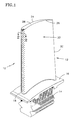
- FIG. 1 is a diagrammatic view of a rotor blade.
- FIG.2 is a diagrammatic cross-sectional view of an airfoil for use in a rotor blade or stator vane.
- FIG.3 is a diagrammatic partial cross-sectional view of an airfoil for use in a rotor blade or stator vane.
-
- Referring to FIG.1, a
rotor blade 10 for use in a gas turbine engine includes ahollow airfoil 12, aroot 14, and aplatform 16 disposed between theroot 14 and theairfoil 12. Thehollow airfoil 12 includes a forward ("leading")edge 18, an aft ("trailing")edge 20, and awall 22 having asuction side portion 24 and apressure side portion 26. Theairfoil 12 extends spanwise between theplatform 16 and theblade tip 28. Theroot 14 includes at least one internal cooling air duct (not shown) for the passage of cooling air up into thehollow airfoil 12. - Referring to FIGS. 2 and 3, the
airfoil wall 22 surrounds afirst cavity 30 and asecond cavity 32, separated from one another by afirst rib 34.Additional ribs 36 separateadditional cavities 38 aft of thesecond cavity 32. Thefirst cavity 30 is contiguous with the leadingedge 18. Thewall 22 includes aninterior surface 40 and anexterior surface 42. Acoolant flow splitter 44, extending out from thewall interior surface 40 within thefirst cavity 30, includes a pair ofsurfaces 46 that intersect at apeak 48, and diverge into thewall interior surface 40. A plurality ofmetering orifices 50 are disposed in thefirst rib 34 between thefirst cavity 30 and thesecond cavity 32. Eachmetering orifice 50 is substantially aligned with thecoolant flow splitter 44, such that cooling air flow passing through themetering orifice 50 encounters theflow splitter 44. - The leading
edge 18 includescooling orifices 52 oriented to create film cooling along thewall exterior surface 42 of theairfoil 12. Thecooling orifices 52 may be arranged in a shower head arrangement as is well known in the prior art. Atrench 54 is disposed in thewall 22, extending spanwise along the leadingedge 18. Thetrench 54 and theflow splitter 44 are substantially aligned with one another on the wallexterior surface 42 and thewall interior surface 40, respectively. Aligning theflow splitter 44 and thetrench 54 minimizes wall thickness deviations in the vicinity of theflow splitter 44. In the embodiment shown,cooling orifices 56 extend through thewall 22, including theflow splitter 44, into the spanwise extendingtrench 54. Cooling air subsequently flows out of thetrench 54 to create film cooling along thesuction side portion 24 and thepressure side portion 26 of theairfoil 12. In a second embodiment (FIG.3), thefirst rib 34 separating thefirst cavity 30 and thesecond cavity 32 has an arcuate shape to promote the formation of acooling air vortex 58 on one or both sides of theflow splitter 44 within thefirst cavity 30. - While the
airfoil 12 is in use, cooling air enters theairfoil 12, for example, via theblade root 14 and directly or indirectly passes into thesecond cavity 32 within thehollow airfoil 12. A portion of the cooling air within thesecond cavity 32 subsequently passes into thefirst cavity 30 through themetering orifices 50 disposed in thefirst rib 34 and encounters theflow splitter 44 extending out from theinterior surface 40 of thewall 22. The positioning of eachmetering orifice 50 relative to theflow splitter 44 dictates what percentage of the cooling air passing through themetering orifice 50 will pass on a particular side of theflow splitter 44. Positioning ametering orifice 50 off center of theflow splitter 44 will cause more than 50% of the cooling air flow to travel along one side of theflow splitter 44, and less than 50% of the cooling air flow to travel along the opposite side of theflow splitter 44. The cooling air passing along theinterior surface 40 of thewall 22 convectively cools thewall 22 and feeds thecooling orifices 52 disposed in that portion of thewall 22. Vortices 58 (FIG.3) developed within thefirst cavity 30 encourage cooling air flow along theinterior wall surface 40 and consequently the convective cooling of that portion of thewall 22. - A portion of the cooling air enters cooling
orifices 56 disposed in thewall 22 and subsequently passes into thetrench 54 along the leadingedge 18. Once in thetrench 54, the cooling air diffuses into cooling air already in thetrench 54 and distributes spanwise along thetrench 54. One of the advantages of distributing cooling air within thetrench 54 is that the pressure difference problems characteristic of conventional cooling orifices are minimized. For example, the difference in pressure across a cooling orifice is a function of the local internal cavity pressure and the local core gas pressure adjacent the orifice. Both of these pressures vary as a function of time. If the core gas pressure is high and the internal cavity pressure is low adjacent a particular cooling orifice in a conventional scheme, undesirable hot core gas in-flow can occur. The preferred embodiment of the present invention minimizes the opportunity for the undesirable in-flow because the cooling air fromorifices 56 collectively distributes within thetrench 54, thereby decreasing the opportunity for any low pressure zones to occur. Likewise, the distribution of cooling air within thetrench 54 also avoids cooling air pressure spikes which, in a conventional scheme, would jet the cooling air into the core gas rather than add it to the film of cooling air downstream. - Cooling air bled along the leading edge via a showerhead and/or a
trench 54 subsequently forms a film of cooling air passing along theexterior surface 42 of theairfoil 12. Undesirable erosion of that film (due to turbulence and other factors) begins almost immediately, thereby negatively effecting the ability of the film to cool and insulate theairfoil 12. To offset the film erosion, it is known to position rows of diffusing type cooling orifices capable of providing cooling air to augment the film. A problem with the prior art is that cooling air within a cavity is not biased toward either wall portion (i.e., thesuction side portion 24 or pressure side portion 26) and it is equally likely to be bled out of eitherwall portion wall portion wall portion flow splitter 44 provides appropriate cooling air flow along each wall portion thereby increasing the cooling efficiency of theairfoil 12. - From the above, it will be seen that there is described an airfoil with a highly efficient internal cooling scheme, an airfoil with an internal cooling scheme that promotes film cooling along the exterior surface of the airfoil and an airfoil with improved cooling features that can be readily manufactured.
- The preferred embodiment of the present invention has been described in terms of a rotor blade airfoil. The present invention is, however, equally applicable to stator vane airfoils as can be seen in FIGS. 2 and 3.
Claims (7)
- A hollow airfoil (12) for a gas turbine engine, having a leading edge (18) and a trailing edge (20), said airfoil comprising:a wall (22), having a suction side portion (24), a pressure side portion (26), an interior surface (40), and an exterior surface (42), said wall surrounding a first cavity (30) and a second cavity (32), said cavities separated from one another by a rib (34) extending between said suction side and said pressure side wall portions,a coolant flow splitter (44), provided on said interior surface (40) within said first cavity (30); andat least one metering orifice (50), disposed in said rib (34), said metering orifice (50) being substantially aligned with said coolant flow splitter (44), such that cooling air passing through said metering orifice (50) encounters said flow splitter (44) and is directed along said interior surface (40) of said wall (22); characterised in that :said first cavity (30) is contiguous with the leading edge (18);said airfoil further comprises a trench (54), disposed in the exterior surface (42) of said wall (22), substantially aligned with the flow splitter (44).
- A hollow airfoil according to claim 1, wherein said coolant flow splitter (44) is substantially aligned with the leading edge (18), extending spanwise along the leading edge (18).
- A hollow airfoil according to claim 1 or 2 further comprising:a plurality of cooling orifices (56), disposed within said wall (22), extending between said trench (54) and said first cavity (30), thereby providing a cooling air passage between said internal cavity (30) and said trench (54).
- A hollow airfoil according to claim 3, wherein said cooling orifices extend through said flow splitter (44).
- A hollow airfoil according to any preceding claim, wherein said rib (34) is arcuately shaped, thereby encouraging the formation of cooling air vortices within said first cavity (30).
- A hollow airfoil according to any preceding claim wherein said metering orifice (50) is aligned with the flow splitter (44) such that cooling air is deflected equally to either side of the flow splitter (44).
- A hollow airfoil according to any of claims 1 to 5 wherein the said metering orifice (50) is aligned off-centre with respect to the flow splitter (44) such that unequal amounts of cooling air will be deflected to either side of the flow splitter (44).
Applications Claiming Priority (2)
| Application Number | Priority Date | Filing Date | Title |
|---|---|---|---|
| US09/110,532 US6099251A (en) | 1998-07-06 | 1998-07-06 | Coolable airfoil for a gas turbine engine |
| US110532 | 1998-07-06 |
Publications (3)
| Publication Number | Publication Date |
|---|---|
| EP0971095A2 EP0971095A2 (en) | 2000-01-12 |
| EP0971095A3 EP0971095A3 (en) | 2000-12-20 |
| EP0971095B1 true EP0971095B1 (en) | 2003-09-03 |
Family
ID=22333544
Family Applications (1)
| Application Number | Title | Priority Date | Filing Date |
|---|---|---|---|
| EP99305036A Expired - Lifetime EP0971095B1 (en) | 1998-07-06 | 1999-06-25 | A coolable airfoil for a gas turbine engine |
Country Status (5)
| Country | Link |
|---|---|
| US (1) | US6099251A (en) |
| EP (1) | EP0971095B1 (en) |
| JP (1) | JP2000038901A (en) |
| KR (1) | KR100572299B1 (en) |
| DE (1) | DE69910913T2 (en) |
Families Citing this family (114)
| Publication number | Priority date | Publication date | Assignee | Title |
|---|---|---|---|---|
| US7892229B2 (en) | 2003-01-18 | 2011-02-22 | Tsunami Medtech, Llc | Medical instruments and techniques for treating pulmonary disorders |
| US8016823B2 (en) | 2003-01-18 | 2011-09-13 | Tsunami Medtech, Llc | Medical instrument and method of use |
| US6368060B1 (en) * | 2000-05-23 | 2002-04-09 | General Electric Company | Shaped cooling hole for an airfoil |
| GB0025012D0 (en) * | 2000-10-12 | 2000-11-29 | Rolls Royce Plc | Cooling of gas turbine engine aerofoils |
| US9433457B2 (en) | 2000-12-09 | 2016-09-06 | Tsunami Medtech, Llc | Medical instruments and techniques for thermally-mediated therapies |
| US7549987B2 (en) | 2000-12-09 | 2009-06-23 | Tsunami Medtech, Llc | Thermotherapy device |
| US6547524B2 (en) * | 2001-05-21 | 2003-04-15 | United Technologies Corporation | Film cooled article with improved temperature tolerance |
| GB0127902D0 (en) * | 2001-11-21 | 2002-01-16 | Rolls Royce Plc | Gas turbine engine aerofoil |
| US8444636B2 (en) | 2001-12-07 | 2013-05-21 | Tsunami Medtech, Llc | Medical instrument and method of use |
| US6884029B2 (en) * | 2002-09-26 | 2005-04-26 | Siemens Westinghouse Power Corporation | Heat-tolerated vortex-disrupting fluid guide component |
| US6971851B2 (en) * | 2003-03-12 | 2005-12-06 | Florida Turbine Technologies, Inc. | Multi-metered film cooled blade tip |
| US6955522B2 (en) * | 2003-04-07 | 2005-10-18 | United Technologies Corporation | Method and apparatus for cooling an airfoil |
| US7281895B2 (en) * | 2003-10-30 | 2007-10-16 | Siemens Power Generation, Inc. | Cooling system for a turbine vane |
| US7121787B2 (en) * | 2004-04-29 | 2006-10-17 | General Electric Company | Turbine nozzle trailing edge cooling configuration |
| US7114923B2 (en) * | 2004-06-17 | 2006-10-03 | Siemens Power Generation, Inc. | Cooling system for a showerhead of a turbine blade |
| MX2007005937A (en) | 2004-11-16 | 2007-09-11 | Robert L Barry | Device and method for lung treatment. |
| JP5039837B2 (en) * | 2005-03-30 | 2012-10-03 | 三菱重工業株式会社 | High temperature components for gas turbines |
| US20070032785A1 (en) | 2005-08-03 | 2007-02-08 | Jennifer Diederich | Tissue evacuation device |
| US7306026B2 (en) * | 2005-09-01 | 2007-12-11 | United Technologies Corporation | Cooled turbine airfoils and methods of manufacture |
| JP4147239B2 (en) * | 2005-11-17 | 2008-09-10 | 川崎重工業株式会社 | Double jet film cooling structure |
| US7534089B2 (en) | 2006-07-18 | 2009-05-19 | Siemens Energy, Inc. | Turbine airfoil with near wall multi-serpentine cooling channels |
| US7520725B1 (en) | 2006-08-11 | 2009-04-21 | Florida Turbine Technologies, Inc. | Turbine airfoil with near-wall leading edge multi-holes cooling |
| US7510367B2 (en) * | 2006-08-24 | 2009-03-31 | Siemens Energy, Inc. | Turbine airfoil with endwall horseshoe cooling slot |
| US7806658B2 (en) * | 2006-10-25 | 2010-10-05 | Siemens Energy, Inc. | Turbine airfoil cooling system with spanwise equalizer rib |
| US7993323B2 (en) | 2006-11-13 | 2011-08-09 | Uptake Medical Corp. | High pressure and high temperature vapor catheters and systems |
| US7927073B2 (en) * | 2007-01-04 | 2011-04-19 | Siemens Energy, Inc. | Advanced cooling method for combustion turbine airfoil fillets |
| US8757974B2 (en) * | 2007-01-11 | 2014-06-24 | United Technologies Corporation | Cooling circuit flow path for a turbine section airfoil |
| US7780414B1 (en) | 2007-01-17 | 2010-08-24 | Florida Turbine Technologies, Inc. | Turbine blade with multiple metering trailing edge cooling holes |
| US7980819B2 (en) * | 2007-03-14 | 2011-07-19 | United Technologies Corporation | Cast features for a turbine engine airfoil |
| WO2009009398A1 (en) | 2007-07-06 | 2009-01-15 | Tsunami Medtech, Llc | Medical system and method of use |
| ATE505147T1 (en) | 2007-08-23 | 2011-04-15 | Aegea Medical Inc | UTERUS THERAPY DEVICE |
| US7878761B1 (en) | 2007-09-07 | 2011-02-01 | Florida Turbine Technologies, Inc. | Turbine blade with a showerhead film cooling hole arrangement |
| US8052390B1 (en) | 2007-10-19 | 2011-11-08 | Florida Turbine Technologies, Inc. | Turbine airfoil with showerhead cooling |
| US8322335B2 (en) * | 2007-10-22 | 2012-12-04 | Uptake Medical Corp. | Determining patient-specific vapor treatment and delivery parameters |
| US8147532B2 (en) * | 2007-10-22 | 2012-04-03 | Uptake Medical Corp. | Determining patient-specific vapor treatment and delivery parameters |
| US8439644B2 (en) * | 2007-12-10 | 2013-05-14 | United Technologies Corporation | Airfoil leading edge shape tailoring to reduce heat load |
| US9924992B2 (en) | 2008-02-20 | 2018-03-27 | Tsunami Medtech, Llc | Medical system and method of use |
| US8246306B2 (en) * | 2008-04-03 | 2012-08-21 | General Electric Company | Airfoil for nozzle and a method of forming the machined contoured passage therein |
| US8721632B2 (en) | 2008-09-09 | 2014-05-13 | Tsunami Medtech, Llc | Methods for delivering energy into a target tissue of a body |
| US8579888B2 (en) | 2008-06-17 | 2013-11-12 | Tsunami Medtech, Llc | Medical probes for the treatment of blood vessels |
| US20100006276A1 (en) * | 2008-07-11 | 2010-01-14 | Johnson Controls Technology Company | Multichannel Heat Exchanger |
| US8105030B2 (en) * | 2008-08-14 | 2012-01-31 | United Technologies Corporation | Cooled airfoils and gas turbine engine systems involving such airfoils |
| US8572844B2 (en) * | 2008-08-29 | 2013-11-05 | United Technologies Corporation | Airfoil with leading edge cooling passage |
| US9561068B2 (en) | 2008-10-06 | 2017-02-07 | Virender K. Sharma | Method and apparatus for tissue ablation |
| EP3175805A1 (en) | 2008-10-06 | 2017-06-07 | Sharma, Virender K. | Apparatus for tissue ablation |
| US9561066B2 (en) | 2008-10-06 | 2017-02-07 | Virender K. Sharma | Method and apparatus for tissue ablation |
| US9561067B2 (en) | 2008-10-06 | 2017-02-07 | Virender K. Sharma | Method and apparatus for tissue ablation |
| US10695126B2 (en) | 2008-10-06 | 2020-06-30 | Santa Anna Tech Llc | Catheter with a double balloon structure to generate and apply a heated ablative zone to tissue |
| US10064697B2 (en) | 2008-10-06 | 2018-09-04 | Santa Anna Tech Llc | Vapor based ablation system for treating various indications |
| US8167558B2 (en) * | 2009-01-19 | 2012-05-01 | Siemens Energy, Inc. | Modular serpentine cooling systems for turbine engine components |
| US11284931B2 (en) | 2009-02-03 | 2022-03-29 | Tsunami Medtech, Llc | Medical systems and methods for ablating and absorbing tissue |
| US8900223B2 (en) | 2009-11-06 | 2014-12-02 | Tsunami Medtech, Llc | Tissue ablation systems and methods of use |
| US9161801B2 (en) | 2009-12-30 | 2015-10-20 | Tsunami Medtech, Llc | Medical system and method of use |
| US9943353B2 (en) | 2013-03-15 | 2018-04-17 | Tsunami Medtech, Llc | Medical system and method of use |
| US8672613B2 (en) * | 2010-08-31 | 2014-03-18 | General Electric Company | Components with conformal curved film holes and methods of manufacture |
| EP2637590B1 (en) | 2010-11-09 | 2022-04-13 | Aegea Medical, Inc. | Positioning apparatus for delivering vapor to the uterus |
| US9022737B2 (en) | 2011-08-08 | 2015-05-05 | United Technologies Corporation | Airfoil including trench with contoured surface |
| CN104135960B (en) | 2011-10-07 | 2017-06-06 | 埃杰亚医疗公司 | Uterine therapy device |
| US20130195650A1 (en) * | 2012-01-27 | 2013-08-01 | Adebukola O. Benson | Gas Turbine Pattern Swirl Film Cooling |
| CN104204412B (en) * | 2012-03-22 | 2016-09-28 | 通用电器技术有限公司 | turbine blade |
| US9429027B2 (en) * | 2012-04-05 | 2016-08-30 | United Technologies Corporation | Turbine airfoil tip shelf and squealer pocket cooling |
| US9482432B2 (en) * | 2012-09-26 | 2016-11-01 | United Technologies Corporation | Gas turbine engine combustor with integrated combustor vane having swirler |
| US9995148B2 (en) | 2012-10-04 | 2018-06-12 | General Electric Company | Method and apparatus for cooling gas turbine and rotor blades |
| US9228440B2 (en) | 2012-12-03 | 2016-01-05 | Honeywell International Inc. | Turbine blade airfoils including showerhead film cooling systems, and methods for forming an improved showerhead film cooled airfoil of a turbine blade |
| US9850762B2 (en) | 2013-03-13 | 2017-12-26 | General Electric Company | Dust mitigation for turbine blade tip turns |
| US9562437B2 (en) * | 2013-04-26 | 2017-02-07 | Honeywell International Inc. | Turbine blade airfoils including film cooling systems, and methods for forming an improved film cooled airfoil of a turbine blade |
| JP5567180B1 (en) | 2013-05-20 | 2014-08-06 | 川崎重工業株式会社 | Turbine blade cooling structure |
| US10775115B2 (en) | 2013-08-29 | 2020-09-15 | General Electric Company | Thermal spray coating method and thermal spray coated article |
| US9782211B2 (en) | 2013-10-01 | 2017-10-10 | Uptake Medical Technology Inc. | Preferential volume reduction of diseased segments of a heterogeneous lobe |
| EP3060761B1 (en) * | 2013-10-23 | 2018-08-22 | United Technologies Corporation | Turbine airfoil cooling core exit |
| EP3074606B1 (en) * | 2013-11-25 | 2022-04-20 | Raytheon Technologies Corporation | Gas turbine engine airfoil with leading edge trench and impingement cooling |
| EP3145425B1 (en) | 2014-05-22 | 2024-10-23 | CooperSurgical, Inc. | Systems for performing endometrial ablation |
| WO2015179662A1 (en) | 2014-05-22 | 2015-11-26 | Aegea Medical Inc. | Integrity testing method and apparatus for delivering vapor to the uterus |
| US10422235B2 (en) | 2014-05-29 | 2019-09-24 | General Electric Company | Angled impingement inserts with cooling features |
| EP3149279A1 (en) | 2014-05-29 | 2017-04-05 | General Electric Company | Fastback turbulator |
| US9957816B2 (en) | 2014-05-29 | 2018-05-01 | General Electric Company | Angled impingement insert |
| EP3149284A2 (en) | 2014-05-29 | 2017-04-05 | General Electric Company | Engine components with impingement cooling features |
| US10364684B2 (en) | 2014-05-29 | 2019-07-30 | General Electric Company | Fastback vorticor pin |
| US9963982B2 (en) * | 2014-09-08 | 2018-05-08 | United Technologies Corporation | Casting optimized to improve suction side cooling shaped hole performance |
| US10280785B2 (en) | 2014-10-31 | 2019-05-07 | General Electric Company | Shroud assembly for a turbine engine |
| US10233775B2 (en) | 2014-10-31 | 2019-03-19 | General Electric Company | Engine component for a gas turbine engine |
| US10485604B2 (en) | 2014-12-02 | 2019-11-26 | Uptake Medical Technology Inc. | Vapor treatment of lung nodules and tumors |
| US10531906B2 (en) | 2015-02-02 | 2020-01-14 | Uptake Medical Technology Inc. | Medical vapor generator |
| US10156157B2 (en) * | 2015-02-13 | 2018-12-18 | United Technologies Corporation | S-shaped trip strips in internally cooled components |
| US20170107827A1 (en) * | 2015-10-15 | 2017-04-20 | General Electric Company | Turbine blade |
| US10352177B2 (en) | 2016-02-16 | 2019-07-16 | General Electric Company | Airfoil having impingement openings |
| ES2929383T3 (en) | 2016-02-19 | 2022-11-28 | Aegea Medical Inc | Methods and apparatus for determining the integrity of a body cavity |
| US10830061B2 (en) * | 2016-03-31 | 2020-11-10 | Siemens Aktiengesellschaft | Turbine airfoil with internal cooling channels having flow splitter feature |
| US20170306764A1 (en) * | 2016-04-26 | 2017-10-26 | General Electric Company | Airfoil for a turbine engine |
| US11331140B2 (en) | 2016-05-19 | 2022-05-17 | Aqua Heart, Inc. | Heated vapor ablation systems and methods for treating cardiac conditions |
| US11286787B2 (en) | 2016-09-15 | 2022-03-29 | Raytheon Technologies Corporation | Gas turbine engine airfoil with showerhead cooling holes near leading edge |
| US10577942B2 (en) * | 2016-11-17 | 2020-03-03 | General Electric Company | Double impingement slot cap assembly |
| US11129673B2 (en) | 2017-05-05 | 2021-09-28 | Uptake Medical Technology Inc. | Extra-airway vapor ablation for treating airway constriction in patients with asthma and COPD |
| US11098596B2 (en) * | 2017-06-15 | 2021-08-24 | General Electric Company | System and method for near wall cooling for turbine component |
| US11344364B2 (en) | 2017-09-07 | 2022-05-31 | Uptake Medical Technology Inc. | Screening method for a target nerve to ablate for the treatment of inflammatory lung disease |
| US11350988B2 (en) | 2017-09-11 | 2022-06-07 | Uptake Medical Technology Inc. | Bronchoscopic multimodality lung tumor treatment |
| USD845467S1 (en) | 2017-09-17 | 2019-04-09 | Uptake Medical Technology Inc. | Hand-piece for medical ablation catheter |
| US10584593B2 (en) | 2017-10-24 | 2020-03-10 | United Technologies Corporation | Airfoil having impingement leading edge |
| US11419658B2 (en) | 2017-11-06 | 2022-08-23 | Uptake Medical Technology Inc. | Method for treating emphysema with condensable thermal vapor |
| US11490946B2 (en) | 2017-12-13 | 2022-11-08 | Uptake Medical Technology Inc. | Vapor ablation handpiece |
| US20190309631A1 (en) * | 2018-04-04 | 2019-10-10 | United Technologies Corporation | Airfoil having leading edge cooling scheme with backstrike compensation |
| CA3102080A1 (en) | 2018-06-01 | 2019-12-05 | Santa Anna Tech Llc | Multi-stage vapor-based ablation treatment methods and vapor generation and delivery systems |
| US11401818B2 (en) | 2018-08-06 | 2022-08-02 | General Electric Company | Turbomachine cooling trench |
| US11499433B2 (en) | 2018-12-18 | 2022-11-15 | General Electric Company | Turbine engine component and method of cooling |
| US11352889B2 (en) | 2018-12-18 | 2022-06-07 | General Electric Company | Airfoil tip rail and method of cooling |
| US10767492B2 (en) | 2018-12-18 | 2020-09-08 | General Electric Company | Turbine engine airfoil |
| US11566527B2 (en) | 2018-12-18 | 2023-01-31 | General Electric Company | Turbine engine airfoil and method of cooling |
| US11174736B2 (en) | 2018-12-18 | 2021-11-16 | General Electric Company | Method of forming an additively manufactured component |
| US11653927B2 (en) | 2019-02-18 | 2023-05-23 | Uptake Medical Technology Inc. | Vapor ablation treatment of obstructive lung disease |
| US10844728B2 (en) | 2019-04-17 | 2020-11-24 | General Electric Company | Turbine engine airfoil with a trailing edge |
| US11585224B2 (en) | 2020-08-07 | 2023-02-21 | General Electric Company | Gas turbine engines and methods associated therewith |
| US11220917B1 (en) * | 2020-09-03 | 2022-01-11 | Raytheon Technologies Corporation | Diffused cooling arrangement for gas turbine engine components |
| CN112302727A (en) * | 2020-11-23 | 2021-02-02 | 华能国际电力股份有限公司 | A cooling structure for the leading edge of a turbine blade |
| US11572803B1 (en) | 2022-08-01 | 2023-02-07 | General Electric Company | Turbine airfoil with leading edge cooling passage(s) coupled via plenum to film cooling holes, and related method |
Family Cites Families (37)
| Publication number | Priority date | Publication date | Assignee | Title |
|---|---|---|---|---|
| NL38642C (en) * | 1934-01-29 | |||
| US3301526A (en) * | 1964-12-22 | 1967-01-31 | United Aircraft Corp | Stacked-wafer turbine vane or blade |
| US3542486A (en) * | 1968-09-27 | 1970-11-24 | Gen Electric | Film cooling of structural members in gas turbine engines |
| GB1355558A (en) * | 1971-07-02 | 1974-06-05 | Rolls Royce | Cooled vane or blade for a gas turbine engine |
| US4545197A (en) * | 1978-10-26 | 1985-10-08 | Rice Ivan G | Process for directing a combustion gas stream onto rotatable blades of a gas turbine |
| US4835958A (en) * | 1978-10-26 | 1989-06-06 | Rice Ivan G | Process for directing a combustion gas stream onto rotatable blades of a gas turbine |
| US4314442A (en) * | 1978-10-26 | 1982-02-09 | Rice Ivan G | Steam-cooled blading with steam thermal barrier for reheat gas turbine combined with steam turbine |
| US4347037A (en) * | 1979-02-05 | 1982-08-31 | The Garrett Corporation | Laminated airfoil and method for turbomachinery |
| US4565490A (en) * | 1981-06-17 | 1986-01-21 | Rice Ivan G | Integrated gas/steam nozzle |
| DE3211139C1 (en) * | 1982-03-26 | 1983-08-11 | MTU Motoren- und Turbinen-Union München GmbH, 8000 München | Axial turbine blades, in particular axial turbine blades for gas turbine engines |
| GB2127105B (en) * | 1982-09-16 | 1985-06-05 | Rolls Royce | Improvements in cooled gas turbine engine aerofoils |
| US4664597A (en) * | 1985-12-23 | 1987-05-12 | United Technologies Corporation | Coolant passages with full coverage film cooling slot |
| US4726735A (en) * | 1985-12-23 | 1988-02-23 | United Technologies Corporation | Film cooling slot with metered flow |
| US4672727A (en) * | 1985-12-23 | 1987-06-16 | United Technologies Corporation | Method of fabricating film cooling slot in a hollow airfoil |
| US4676719A (en) * | 1985-12-23 | 1987-06-30 | United Technologies Corporation | Film coolant passages for cast hollow airfoils |
| US4738588A (en) * | 1985-12-23 | 1988-04-19 | Field Robert E | Film cooling passages with step diffuser |
| US4669957A (en) * | 1985-12-23 | 1987-06-02 | United Technologies Corporation | Film coolant passage with swirl diffuser |
| US4653983A (en) * | 1985-12-23 | 1987-03-31 | United Technologies Corporation | Cross-flow film cooling passages |
| US4762464A (en) * | 1986-11-13 | 1988-08-09 | Chromalloy Gas Turbine Corporation | Airfoil with diffused cooling holes and method and apparatus for making the same |
| US4753575A (en) * | 1987-08-06 | 1988-06-28 | United Technologies Corporation | Airfoil with nested cooling channels |
| US4859147A (en) * | 1988-01-25 | 1989-08-22 | United Technologies Corporation | Cooled gas turbine blade |
| GB2227965B (en) * | 1988-10-12 | 1993-02-10 | Rolls Royce Plc | Apparatus for drilling a shaped hole in a workpiece |
| GB2228540B (en) * | 1988-12-07 | 1993-03-31 | Rolls Royce Plc | Cooling of turbine blades |
| JPH0663442B2 (en) * | 1989-09-04 | 1994-08-22 | 株式会社日立製作所 | Turbine blades |
| GB2242941B (en) * | 1990-04-11 | 1994-05-04 | Rolls Royce Plc | A cooled gas turbine engine aerofoil |
| US5405242A (en) * | 1990-07-09 | 1995-04-11 | United Technologies Corporation | Cooled vane |
| FR2689176B1 (en) * | 1992-03-25 | 1995-07-13 | Snecma | DAWN REFRIGERATED FROM TURBO-MACHINE. |
| US5356265A (en) * | 1992-08-25 | 1994-10-18 | General Electric Company | Chordally bifurcated turbine blade |
| US5690473A (en) * | 1992-08-25 | 1997-11-25 | General Electric Company | Turbine blade having transpiration strip cooling and method of manufacture |
| US5403159A (en) * | 1992-11-30 | 1995-04-04 | United Technoligies Corporation | Coolable airfoil structure |
| US5419681A (en) * | 1993-01-25 | 1995-05-30 | General Electric Company | Film cooled wall |
| US5486093A (en) * | 1993-09-08 | 1996-01-23 | United Technologies Corporation | Leading edge cooling of turbine airfoils |
| US5374162A (en) * | 1993-11-30 | 1994-12-20 | United Technologies Corporation | Airfoil having coolable leading edge region |
| US5387085A (en) * | 1994-01-07 | 1995-02-07 | General Electric Company | Turbine blade composite cooling circuit |
| FR2715693B1 (en) * | 1994-02-03 | 1996-03-01 | Snecma | Fixed or mobile turbine-cooled blade. |
| US5458461A (en) * | 1994-12-12 | 1995-10-17 | General Electric Company | Film cooled slotted wall |
| US5498133A (en) * | 1995-06-06 | 1996-03-12 | General Electric Company | Pressure regulated film cooling |
-
1998
- 1998-07-06 US US09/110,532 patent/US6099251A/en not_active Expired - Lifetime
-
1999
- 1999-06-25 EP EP99305036A patent/EP0971095B1/en not_active Expired - Lifetime
- 1999-06-25 DE DE69910913T patent/DE69910913T2/en not_active Expired - Lifetime
- 1999-07-02 KR KR1019990026646A patent/KR100572299B1/en not_active Expired - Fee Related
- 1999-07-05 JP JP11189835A patent/JP2000038901A/en active Pending
Also Published As
| Publication number | Publication date |
|---|---|
| EP0971095A3 (en) | 2000-12-20 |
| JP2000038901A (en) | 2000-02-08 |
| KR20000011450A (en) | 2000-02-25 |
| DE69910913D1 (en) | 2003-10-09 |
| EP0971095A2 (en) | 2000-01-12 |
| US6099251A (en) | 2000-08-08 |
| KR100572299B1 (en) | 2006-04-24 |
| DE69910913T2 (en) | 2004-05-13 |
Similar Documents
| Publication | Publication Date | Title |
|---|---|---|
| EP0971095B1 (en) | A coolable airfoil for a gas turbine engine | |
| US8246307B2 (en) | Blade for a rotor | |
| US6210112B1 (en) | Apparatus for cooling an airfoil for a gas turbine engine | |
| EP0330601B1 (en) | Cooled gas turbine blade | |
| JP4659206B2 (en) | Turbine nozzle with graded film cooling | |
| EP1882820B1 (en) | Microcircuit cooling and blade tip blowing | |
| US6283708B1 (en) | Coolable vane or blade for a turbomachine | |
| US6607355B2 (en) | Turbine airfoil with enhanced heat transfer | |
| US5738493A (en) | Turbulator configuration for cooling passages of an airfoil in a gas turbine engine | |
| US7195458B2 (en) | Impingement cooling system for a turbine blade | |
| US5413458A (en) | Turbine vane with a platform cavity having a double feed for cooling fluid | |
| US6213714B1 (en) | Cooled airfoil | |
| EP1467064B1 (en) | Cooled Hollow airfoil | |
| CN106437863B (en) | Turbine engine component | |
| US7661930B2 (en) | Central cooling circuit for a moving blade of a turbomachine | |
| US20010016162A1 (en) | Cooled blade for a gas turbine | |
| EP3063376B1 (en) | Gas turbine engine component comprising a trailing edge cooling using angled impingement on surface enhanced with cast chevron arrangements | |
| US8052390B1 (en) | Turbine airfoil with showerhead cooling | |
| US20170030198A1 (en) | Method for cooling a turbo-engine component and turbo-engine component | |
| EP0924384A2 (en) | Airfoil with leading edge cooling | |
| KR970707364A (en) | Gas turbine blades with cooled platform (GAS TURBINE BLADE WITH A COOLED PLATFORM) | |
| EP1484476B1 (en) | Cooled platform for a turbine nozzle guide vane or rotor blade | |
| JP2002364305A (en) | Blade or vane to be cooled for turbine engine | |
| JPH11247607A (en) | Turbine blade |
Legal Events
| Date | Code | Title | Description |
|---|---|---|---|
| PUAI | Public reference made under article 153(3) epc to a published international application that has entered the european phase |
Free format text: ORIGINAL CODE: 0009012 |
|
| AK | Designated contracting states |
Kind code of ref document: A2 Designated state(s): DE FR GB |
|
| AX | Request for extension of the european patent |
Free format text: AL;LT;LV;MK;RO;SI |
|
| PUAL | Search report despatched |
Free format text: ORIGINAL CODE: 0009013 |
|
| AK | Designated contracting states |
Kind code of ref document: A3 Designated state(s): AT BE CH CY DE DK ES FI FR GB GR IE IT LI LU MC NL PT SE |
|
| AX | Request for extension of the european patent |
Free format text: AL;LT;LV;MK;RO;SI |
|
| 17P | Request for examination filed |
Effective date: 20010523 |
|
| AKX | Designation fees paid |
Free format text: DE FR GB |
|
| 17Q | First examination report despatched |
Effective date: 20020322 |
|
| GRAH | Despatch of communication of intention to grant a patent |
Free format text: ORIGINAL CODE: EPIDOS IGRA |
|
| GRAH | Despatch of communication of intention to grant a patent |
Free format text: ORIGINAL CODE: EPIDOS IGRA |
|
| GRAA | (expected) grant |
Free format text: ORIGINAL CODE: 0009210 |
|
| AK | Designated contracting states |
Kind code of ref document: B1 Designated state(s): DE FR GB |
|
| REG | Reference to a national code |
Ref country code: GB Ref legal event code: FG4D |
|
| REF | Corresponds to: |
Ref document number: 69910913 Country of ref document: DE Date of ref document: 20031009 Kind code of ref document: P |
|
| ET | Fr: translation filed | ||
| PLBE | No opposition filed within time limit |
Free format text: ORIGINAL CODE: 0009261 |
|
| STAA | Information on the status of an ep patent application or granted ep patent |
Free format text: STATUS: NO OPPOSITION FILED WITHIN TIME LIMIT |
|
| 26N | No opposition filed |
Effective date: 20040604 |
|
| PGFP | Annual fee paid to national office [announced via postgrant information from national office to epo] |
Ref country code: FR Payment date: 20100709 Year of fee payment: 12 |
|
| REG | Reference to a national code |
Ref country code: FR Ref legal event code: ST Effective date: 20120229 |
|
| PG25 | Lapsed in a contracting state [announced via postgrant information from national office to epo] |
Ref country code: FR Free format text: LAPSE BECAUSE OF NON-PAYMENT OF DUE FEES Effective date: 20110630 |
|
| PGFP | Annual fee paid to national office [announced via postgrant information from national office to epo] |
Ref country code: GB Payment date: 20150527 Year of fee payment: 17 Ref country code: DE Payment date: 20150521 Year of fee payment: 17 |
|
| REG | Reference to a national code |
Ref country code: DE Ref legal event code: R119 Ref document number: 69910913 Country of ref document: DE |
|
| GBPC | Gb: european patent ceased through non-payment of renewal fee |
Effective date: 20160625 |
|
| PG25 | Lapsed in a contracting state [announced via postgrant information from national office to epo] |
Ref country code: DE Free format text: LAPSE BECAUSE OF NON-PAYMENT OF DUE FEES Effective date: 20170103 |
|
| PG25 | Lapsed in a contracting state [announced via postgrant information from national office to epo] |
Ref country code: GB Free format text: LAPSE BECAUSE OF NON-PAYMENT OF DUE FEES Effective date: 20160625 |