JP4659206B2 - Turbine nozzle with graded film cooling - Google Patents
Turbine nozzle with graded film cooling Download PDFInfo
- Publication number
- JP4659206B2 JP4659206B2 JP2000381143A JP2000381143A JP4659206B2 JP 4659206 B2 JP4659206 B2 JP 4659206B2 JP 2000381143 A JP2000381143 A JP 2000381143A JP 2000381143 A JP2000381143 A JP 2000381143A JP 4659206 B2 JP4659206 B2 JP 4659206B2
- Authority
- JP
- Japan
- Prior art keywords
- film cooling
- holes
- rib
- side wall
- row
- Prior art date
- Legal status (The legal status is an assumption and is not a legal conclusion. Google has not performed a legal analysis and makes no representation as to the accuracy of the status listed.)
- Expired - Fee Related
Links
Images


Classifications
-
- F—MECHANICAL ENGINEERING; LIGHTING; HEATING; WEAPONS; BLASTING
- F01—MACHINES OR ENGINES IN GENERAL; ENGINE PLANTS IN GENERAL; STEAM ENGINES
- F01D—NON-POSITIVE DISPLACEMENT MACHINES OR ENGINES, e.g. STEAM TURBINES
- F01D5/00—Blades; Blade-carrying members; Heating, heat-insulating, cooling or antivibration means on the blades or the members
- F01D5/12—Blades
- F01D5/14—Form or construction
- F01D5/18—Hollow blades, i.e. blades with cooling or heating channels or cavities; Heating, heat-insulating or cooling means on blades
- F01D5/186—Film cooling
-
- F—MECHANICAL ENGINEERING; LIGHTING; HEATING; WEAPONS; BLASTING
- F01—MACHINES OR ENGINES IN GENERAL; ENGINE PLANTS IN GENERAL; STEAM ENGINES
- F01D—NON-POSITIVE DISPLACEMENT MACHINES OR ENGINES, e.g. STEAM TURBINES
- F01D5/00—Blades; Blade-carrying members; Heating, heat-insulating, cooling or antivibration means on the blades or the members
- F01D5/12—Blades
- F01D5/14—Form or construction
- F01D5/18—Hollow blades, i.e. blades with cooling or heating channels or cavities; Heating, heat-insulating or cooling means on blades
- F01D5/187—Convection cooling
-
- F—MECHANICAL ENGINEERING; LIGHTING; HEATING; WEAPONS; BLASTING
- F01—MACHINES OR ENGINES IN GENERAL; ENGINE PLANTS IN GENERAL; STEAM ENGINES
- F01D—NON-POSITIVE DISPLACEMENT MACHINES OR ENGINES, e.g. STEAM TURBINES
- F01D9/00—Stators
- F01D9/02—Nozzles; Nozzle boxes; Stator blades; Guide conduits, e.g. individual nozzles
- F01D9/04—Nozzles; Nozzle boxes; Stator blades; Guide conduits, e.g. individual nozzles forming ring or sector
- F01D9/041—Nozzles; Nozzle boxes; Stator blades; Guide conduits, e.g. individual nozzles forming ring or sector using blades
-
- F—MECHANICAL ENGINEERING; LIGHTING; HEATING; WEAPONS; BLASTING
- F05—INDEXING SCHEMES RELATING TO ENGINES OR PUMPS IN VARIOUS SUBCLASSES OF CLASSES F01-F04
- F05D—INDEXING SCHEME FOR ASPECTS RELATING TO NON-POSITIVE-DISPLACEMENT MACHINES OR ENGINES, GAS-TURBINES OR JET-PROPULSION PLANTS
- F05D2260/00—Function
- F05D2260/20—Heat transfer, e.g. cooling
- F05D2260/221—Improvement of heat transfer
- F05D2260/2214—Improvement of heat transfer by increasing the heat transfer surface
- F05D2260/22141—Improvement of heat transfer by increasing the heat transfer surface using fins or ribs
-
- Y—GENERAL TAGGING OF NEW TECHNOLOGICAL DEVELOPMENTS; GENERAL TAGGING OF CROSS-SECTIONAL TECHNOLOGIES SPANNING OVER SEVERAL SECTIONS OF THE IPC; TECHNICAL SUBJECTS COVERED BY FORMER USPC CROSS-REFERENCE ART COLLECTIONS [XRACs] AND DIGESTS
- Y02—TECHNOLOGIES OR APPLICATIONS FOR MITIGATION OR ADAPTATION AGAINST CLIMATE CHANGE
- Y02T—CLIMATE CHANGE MITIGATION TECHNOLOGIES RELATED TO TRANSPORTATION
- Y02T50/00—Aeronautics or air transport
- Y02T50/60—Efficient propulsion technologies, e.g. for aircraft
-
- Y—GENERAL TAGGING OF NEW TECHNOLOGICAL DEVELOPMENTS; GENERAL TAGGING OF CROSS-SECTIONAL TECHNOLOGIES SPANNING OVER SEVERAL SECTIONS OF THE IPC; TECHNICAL SUBJECTS COVERED BY FORMER USPC CROSS-REFERENCE ART COLLECTIONS [XRACs] AND DIGESTS
- Y10—TECHNICAL SUBJECTS COVERED BY FORMER USPC
- Y10S—TECHNICAL SUBJECTS COVERED BY FORMER USPC CROSS-REFERENCE ART COLLECTIONS [XRACs] AND DIGESTS
- Y10S416/00—Fluid reaction surfaces, i.e. impellers
- Y10S416/02—Formulas of curves
Landscapes
- Engineering & Computer Science (AREA)
- Mechanical Engineering (AREA)
- General Engineering & Computer Science (AREA)
- Turbine Rotor Nozzle Sealing (AREA)
Description
【0001】
【発明の属する技術分野】
本発明は概してガスタービンエンジンに関し、さらに詳細にはガスタービンエンジン内のタービンノズルに関する。
【0002】
【従来の技術】
ガスタービンエンジンにおいて、空気は圧縮機内で加圧され、燃焼器内で燃料と混合され点火されて高温燃焼ガスが発生する。ガスは、支持用円板から半径方向外側に延びるタービン動翼列に向けてガスを導くステータ翼を備える第1段高圧タービンノズルを通して吐出される。
【0003】
タービン翼は燃焼ガスからエネルギーを抽出して圧縮機に動力を供給する。ガスはその後、一般的にターボファン航空機エンジンのファンへの動力供給等の出力作業を行うためにガスからさらにエネルギーを抽出する数段のノズル翼と動翼とを有する低圧タービンへ導かれる。
【0004】
高圧タービンノズルは最初に燃焼器からの燃焼ガスを受取るので、適当な耐用寿命を持たせるためには冷却が必要である。一般的なタービンノズルは、円周方向に互いに離間する外側と内側の環状バンドの間に翼長方向に半径方向に延びる一列のエーロフォイル翼を備えている。各々の翼の冷却用の圧縮機からの吐出ガスの一部を受取るよう翼は中空になっている。
【0005】
各々の翼内には、対応する半径方向に延びるリブまたは隔壁によって内部冷却通路が形成されており、リブまたは隔壁は、円周方向に対向する正圧側と負圧側の側壁へ一体的に連結されている。翼の内面は、伝熱冷却を高めるよう運転中にそれを越えて流れる冷却空気を乱す背の低い乱流部材(turbulator)を備えてもよい。
【0006】
翼の外面に沿って流れる高温燃焼ガスから該外壁を保護するために、種々の放射状列のフイルム冷却孔が翼の正圧側と負圧側の側壁に設けられている。
【0007】
翼の前縁は最初に高温燃焼ガスを受取るので、典型的にシャワーヘッド形状の数列のフイルム冷却孔を備えている。フイルム冷却孔から吐出される空気は、翼の外面に沿って冷却空気の境界層を生成し、列から列へ付加的な冷却空気で再びエネルギーが与えられる。このフイルム冷却空気は、運転中に金属翼を高温燃焼ガスから保護する防壁をもたらす。
【0008】
典型的なエーロフォイル翼は、前縁の後方で厚さが増し、典型的には翼弦長の3分の1以内で最大厚さに達し、その後先細になり厚さを減じながら比較的薄い後縁に至る。翼が後縁の近くで薄くなるにつれて翼の後縁領域を冷却することは困難になる。従って後縁は運転中に比較的高温に曝される別の領域である。
【0009】
典型的に後縁は内部対流冷却をもたらす一列の後縁吐出孔によって冷却される。また、正圧側壁を保護し、更なる保護を図るために下流方向後縁へ延びる冷却空気フイルムを発達させるために、正圧側壁に一列またはそれ以上の付加的なフイルム冷却孔を設けてもよい。
【0010】
さらに、負圧側壁は、前縁と最大厚さ領域との間に数列のフイルム冷却用のえら孔(gill hole)を含んでもよく、これにより負圧側壁を保護するための冷却空気フイルムが発達し、後縁へ流れて後縁をさらに保護する。
【0011】
燃焼ガスは、翼の正圧側及び負圧側の側壁に沿って異なる速度で流れるので、翼の前縁から後縁までの種々の領域は様々な加熱量に曝され、これに対応して様々な冷却量を必要とする。ノズル翼の冷却のために燃焼器から迂回されるいかなる空気もエンジン全体の能率を低下させるので、その量は適当なノズル翼の耐用寿命を達成しながら最少限にとどめる必要がある。
【0012】
燃焼ガスの加熱効果の変動と冷却空気の冷却効果の変動とは温度勾配を生じるので翼の設計をさらに複雑にする。温度勾配は、翼材料の異なる膨張と収縮をもたらし、これは運転中の翼の低周波疲労による寿命に影響を及ぼす、熱的に誘発される歪みと応力の原因となる。
【0013】
例えば、隔壁またはリブは、翼の正圧側と負圧側との間に延びる対応する冷却通路を形成し、それに沿って導かれる空気によって翼の内部で保護され冷却されるので本質的に比較的低温である。比較的高温の翼の正圧側及び負圧側の側壁に比べこのリブは比較的低温であり、両者の間には相当大きな温度勾配が生じる。さらに、翼の前縁と後縁の間で正圧側と負圧側に沿って異なる大きさの温度勾配も生じる。
【0014】
従って、従来技術にあっては、様々な複雑さと効果の度合い及び様々な耐用寿命を有する種々の形状の冷却タービンノズル翼が多数存在している。
【0015】
例えば、ゼネラルエレクトリック社はCF34という名前のターボファン航空機用ガスタービンエンジンを製造販売しており、このエンジンは数十年に亘り商業的に成功し使用されている。このエンジンの高圧タービンノズルは、顕著な耐用寿命を持つフイルム冷却されう翼を備えている。このエンジンの数十年に亘る商業用途は、タービンノズルの耐久性と寿命を評価するための数千時間の実地経験をもたらしている。
【0016】
このノズルの設計の広範囲に及ぶ解析に関連するそのような実地経験は、今や必要とする空気量を増加することなくタービンノズルの耐久性と寿命を改善するために利用できる。
【0017】
【発明が解決しようとする課題】
従って、冷却空気量の増加させることなく改善された耐久性をもち、広範囲に及ぶ実地経験と解析に基づいて改良されたタービンノズルを提供することが望まれている。
【0018】
【課題を解決するための手段】
タービンノズル翼は、前縁と後縁との間に延びる正圧側及び負圧側の側壁を備える。翼は前縁と後縁との間に3本の内部冷却通路を形成する一体式の一対のリブを備える。複数列のフイルム冷却用の孔は側壁に沿って延び、正圧側の3列は、エーロフォイルの翼長に沿って種々の勾配で傾斜している。
【0019】
【発明の実施の形態】
本発明の好ましい例示的な実施形態と他の目的及び利点は、添付の図面を参照して以下の詳細な説明によって具体的に説明されている。
【0020】
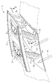
図1は、飛行中の航空機に動力を供給するよう構成されたターボファンガスタービンエンジンの第1段高圧タービンノズル14の一部を示す。エンジンは、連続流れ連通関係で、ファン、多段圧縮機及びノズルから排出される高温燃焼ガス16を発生するよう燃料を圧縮機からの圧縮空気と混合する燃焼器(図示せず)を備えている。
【0021】
ノズル下流には、一列の第1段タービンロータブレード(図示せず)が配置され、それに続いて運転中にファンに動力を供給する低圧タービン(図示せず)が配置されている。
【0022】
図1にその一部を示すタービンノズルは、軸方向の中心線軸まわりに軸対称であり、対向する半径方向端部において対応する半径方向の内側及び外側のバンド20,22に一体的に連結される複数のノズル翼18を備える。バンドは部分的に図示されており、典型的にはセグメントあたり2本またはそれ以上の翼を備える扇形セグメントの形状に形成されている。運転中、高温燃焼ガス16に備えて翼を冷却するために、冷却空気24は、圧縮機の吐出口から適当に迂回されて、典型的には外側バンド22を通って各々の翼に供給される。
【0023】
図1及び2に示すように、各々の翼18は、全体的に凹形の正圧側壁26と円周方向に向かい合う全体的に凸形の負圧側壁28とを備えている。図3に示すように、2枚の側壁は、縦方向に2つのバンド20と22との間のノズルの放射軸に沿って延びており、根元30は前者即ち内側バンドに連結し、先端32は後者即ち外側バンドに連結している。また、2枚の側壁は対向する前縁と後縁34,36の間で翼弦方向即ち軸方向に延びている。
【0024】
図2及び3に示すように、2枚の翼の側壁は、前縁と後縁との間で円周方向に互いに離間する、典型的には共通の鋳造で一体に形成された内部リブまたは隔壁を備えている。第1のリブ38は、前縁から後方に隔たり、第2のリブ40は、第1リブから後方に且つ後縁から前方に隔たっている。
【0025】
第1のリブは、翼の前縁領域で冷却空気24を翼の内部に導くための第1のつまり前縁通路を形成する。また、第2のリブ40は、第1のリブから隔たり第2のつまり翼弦中央通路を形成し、これも冷却空気の一部を導く。また、第2のリブは後縁から隔たり、その間に第3のつまり後縁通路を形成し、これも同様に運転中に冷却空気の別の一部を導く。図1及び3に示すように、冷却空気は、外側バンド22の対応する導入口から適切に3つの通路に供給される。
【0026】
まず図2に示すように、各々の翼18は、本発明によって翼の温度と温度勾配を低下させてノズル翼の耐久性と寿命を実質的に高めるよう改良されたフイルム冷却を提供するために、3つの通路42,44,46のそれぞれと連通しており、1−13の番号を付した正圧側及び負圧側に延びる複数列の対応するフイルム冷却用の孔を備えている。種々のフイルム冷却孔は、半径方向に全体的に直線状に翼長に沿って延びている。
【0027】
図1−3に示す1−13のフイルム冷却用孔の改良されたパターン及び構成を除いては、図示のタービンノズルは従来型であり、前記CF34エンジンの高圧タービンノズルに対応している。前述のように、エンジンの広範囲に及ぶ実地経験から、現行のフイルム冷却孔のパターンと構成とに起因するタービンノズルの局所的な熱障害が明らかになっている。実地経験とその広範囲な解析から、フイルム冷却孔の改良されたパターンと構成とは、現行のノズル設計に比べて耐久性と寿命とを約3倍高める実質的な改良であることが判明している。
【0028】
図2及び3に示すように、第1隔壁リブ38は、内側バンド20から外側バンド22を貫通する空気導入口に達する手前まで半径方向外側に延びている。第1リブ38は、著しい傾斜や勾配なしに半径方向に指向している。
【0029】
第2隔壁リブ40は、外側バンド22の空気導入口から内側バンド20に達する手前まで半径方向内側に延びている。第2リブ40は、放射軸に対して角度Aで傾斜しており、リブの内側端は外側端よりもよりも後方に配置されている。この構成において、第1リブ38は、外側バンドの共通の導入口から冷却空気24を受取る第1及び第2空気通路42,44を区分けする。
【0030】
第1通路42の内側は、冷却空気が通路内に妨げなく導かれるよう滑らかであることが好ましい。第2通路44の内側も滑らかであることが好ましいが、図2に示すように、半径方向内側を流れる冷却空気を乱してこの領域の正圧側壁26の伝熱冷却を向上させるための背の低い直線状の乱流板48を備えている。
【0031】
第3通路46は、正圧側及び負圧側の側壁26,28の間に一体的に延びる縦方向及び翼弦方向に隔てられたピン50の列(bank)を備えており、第3通路46によって冷却空気が供給される翼の先細の後縁領域に沿う空気の冷却効果を高めている。
【0032】
リブ38,40と通路42−46とは、現行のCF34のノズルと同様のものある。
【0033】
各々の翼18のフイルム孔は、前縁と後縁との間のエーロフォイル形状の正圧側壁と負圧側壁との異なる冷却要求に応じて異なるグループに配置されている。第1グループは、第1及び第2通路42,44のそれぞれの1つと連通しており負圧側の側壁28を貫通する4列のフイルム冷却用えら孔1,2,3,12を含んでいる。図1及び3に示すように、4列のえら孔は、第1リブ38に沿う翼長に沿って直線状に延びている。
【0034】
図2に示す4列のえら孔は、前縁のすぐ後方から翼の最大厚さまで負圧側壁に沿って翼弦方向に隔てられている。1列のえら孔1は、冷却空気を受取るよう第1リブ38のすぐ後方で第2通路44に連通している。さらに3本の列2,3,12はこの通路から冷却用空気を受取るよう上流側つまり第1リブ38の前方で第1通路42と連通している。
【0035】
図1及び2に示すように、さらに各々の翼は、前縁34で翼長に沿って直線状に延びるシャワーヘッド形状に配置された4列のフイルム冷却孔を備えている。4つのシャワーヘッド列4,5,6,7は、前縁の周りに正圧側と負圧側との側壁に沿って横方向に隔てられている。
【0036】
図2及び3に示すように、フイルム冷却孔として、第1、第2及び第3通路42,44,46のそれぞれの1つと連通し、正圧側壁26を貫通して延びる別のグループの4列のフイルム冷却側壁孔8,9,10,13が設けられている。
【0037】
翼弦中央部の列の側壁孔8は、空気を受取るよう第2通路44と連通している。側壁孔の後方の2列9,10は、空気を受取るよう第3通路46と連通している。さらに、前列の側壁孔13は、冷却用空気を受取るよう第1通路42と連通している。
【0038】
図2及び3に示すように、さらに各々の翼は、後縁36に沿って延び冷却空気を受取るよう第3通路46と連通する後縁孔11を備えている。後縁孔11は、対向する正圧側と負圧側との間で軸方向に延び、それに沿って冷却空気の最終フイルムを吐出するよう後縁36のすぐ前方に隔てられた吐出口を有している。
【0039】
前述のように、翼のエーロフォイル形状によって翼は、この翼の周りで様々な挙動を示す燃焼ガスの熱の曝される。従って、運転中の翼の耐久性を高めるためには、フイルム冷却孔を運転中の好ましくない温度勾配を低減して、局所ホットスポットの温度を最小にするよう正確に形成して配置する必要がある。
【0040】
特に、3列の側壁孔の8,9,10は、各々の翼長に沿って異なる勾配または傾斜角B,Cで傾斜しているのが好ましい。改良された形状の3列の側壁孔8,9,10は、後縁に至る正圧側壁に沿って軸方向の温度勾配を低減して耐久性を向上させる。
【0041】
図3に示すように、第2リブ40は傾斜角Aの勾配を有し、翼弦中央列の側壁孔8は、第2リブの直上流で第2通路44に連通して第2リブに沿って正圧側壁にフイルム冷却空気を吐出するよう、好ましくは第2リブの勾配Aに等しい勾配Bを有している。
【0042】
側壁孔8は、側壁孔8の上流側列の勾配Bよりも小さく且つ第2リブ40の勾配Aよりも小さい勾配Cで半径方向に一直線に並べられた下流側の列の側壁孔9と協働する。図3において、種々のフイルム冷却孔は、仮想線で示すように全体的に直線状で半径方向に並べられている。
【0043】
最下流の列の側壁孔10は、中間列側壁孔9の勾配Cよりも小さな勾配を有し、中間側壁孔9の後方で第3通路に直接連通している。最下流の列の側壁孔10の勾配はゼロであることが望ましく、これはノズルの放射軸との縦方向の整列を示している。
【0044】
図3に示すリブ40は、放射軸に対して、同時に全体的に半径方向に整列された後縁36に対しても勾配を有しているので、比較的低温の第2リブ40に比べて比較的高温である、翼の正圧側壁に沿う温度勾配を低減するようフイルム冷却空気を良好に配分するために、3列の側壁孔8,9,10の相対的な方向または勾配を変えることが望ましい。1つの好適な実施形態において、中間列の側壁孔9の勾配Cは、隣の上流側列の側壁孔8と、隣の下流側列の側壁孔10の勾配の平均値であるのが好ましい。
【0045】
翼弦中央列の側壁孔8の勾配に照らして、第4列の側壁孔13は、その上流で第1通路42と連通して第1リブ38に沿って設けらている。側壁孔13の上流側の列は、実質的に第1リブ38に平行であり全体的にゼロ勾配であることが好ましい。
【0046】
図示されている13列のフイルム冷却孔1−13のパターン及び構成は、長年にわたり販売され運転されてきた商業用途の多数のエンジンの熱障害を呈する従来のCF34のノズル設計との比較において評価できる。
【0047】
下の表は、過去のCF34の設計と、本発明の好適な実施形態による改良されアップグレードされた設計との間の付加的な相違点を示す。表中、フイルム冷却孔の列ごとに一列あたりの孔の数と、ミルとミリメータ単位での直径とが示されている。

【0048】
第1の上流側列のえら孔12は、それより下流側のより大きいえら孔1−3よりも直径が小さい。えら孔2,3の大きさと個数は従来と同様であり、追加したえら孔12の列と良好に協働するよう、えら孔3の列を前縁方向に移動した。えら孔1の後方の列は、上流側の3列のえら孔によって良好に冷却されることに照らして僅かに後方へ移動した。
【0049】
フイルム層を拡張するために、えら孔1の数を翼の根元付近で少し増やした。えら孔1の列を翼根元へ拡張することで付加的な冷却がもたらされて翼後縁の寿命が向上する。後縁の耐久性を改善することにより、エンジン性能の低下を防止できる。
【0050】
シャワーヘッド孔4−7の直径は、そこから吐出される冷却空気量を減らすために縮小され、シャワーヘッド孔を4列の側壁孔8−10,13と実質的に同じ直径とした。シャワーヘッド孔4−7は、図3に示す約20度の半径方向内側の傾斜角Dを有しており、従来設計での約45度の角度に比べて実質的に急角度である。
【0051】
シャワーヘッド孔4−7の変更は、従来設計のものと同等の金属温度をもたらすが、通過する冷却空気の流れを低減する。シャワーヘッド孔の縮小された直径と急な表面角度とにより冷却効果が高まり、冷却空気の必要量が減り、冷却空気は他のフイルム孔へ分散した。他の孔は、各々の翼の全てのフイルム冷却列の要求量が実質的に従来設計と同じであるようにそれ相応に寸法が定められている。
【0052】
表に示すように、3列の側壁孔8,9,10は、実質的に直径が縮小されているので、この3列の好適な勾配と協働する、そこを通過する空気量が低減する。さらに、エーロフォイルの正圧側壁上の温度勾配を低減するために3列の下流側壁と協働するよう前側列の側壁孔13を付加した。
【0053】
フイルム冷却用側壁孔8,9,10の直径は従来設計に比べて実質的に小さくなり、ここでは実質的に直径が等しく、さらに新たに付加した列の側壁孔13と直径が等しい。
【0054】
4列の側壁孔8−10,13は、翼の耐久性を高めるために正圧側壁上に沿って実質的に温度勾配を低減するよう、ここでは正圧側壁26と比較的低温のリブ38,40及びピン50と協働する。側壁孔の前方と後方の列13,10は、翼に関して半径方向にほぼ一直線に並んでいるが、一方で中間列の側壁孔8,9は勾配を有する第2リブ40と協働するよう勾配を有している。
【0055】
好適な実施形態において、翼弦中間列の側壁孔の8は、第2リブの勾配に一致しており、隣の下流側列の側壁孔9の勾配は、上流側列の側壁孔と下流側列の側壁孔との平均値を有している。
【0056】
所望で有れば、1つまたはそれ以上の付加的なフイルム冷却用側壁孔の列を追加してもよく、中間的な勾配をもつことが好ましい。3列8,9,10に関して、中間列の勾配は単に2つの隣接列の平均勾配である。さらに、4列の側壁孔の(図示せず)に関して、第2の中間列の勾配は、2つの外側の列の勾配の和の3分の1だけ第1列と異なり、また第3列の勾配については、勾配の和の3分の1だけ第4列と異なる。
【0057】
改良されたノズル翼18は、広範囲に及ぶ実地経験と解析とによって可能となったフイルム冷却孔の注意深い組み合わせによって、向上した耐久性と寿命とを享受している。
【0058】
本明細書では本発明の好ましい例示的な実施形態と考えるものについて説明してきたが、本発明の他の形態は明細書の教示内容から当業者には自明であり、本発明の真の精神と発明の範囲に属する全ての変更は特許請求の範囲で保護されるものである。
【図面の簡単な説明】
【図1】本発明の例示的な実施形態による環状ガスタービンエンジンの扇型セグメント、高圧タービンノズルの等角投影図である。
【図2】図1に示されるノズル翼の1つを線2−2に沿って見た半径方向断面図である。
【図3】図1に示されるノズル翼をキャンバーライン3−3に沿って見た軸方向立面図である。[0001]
BACKGROUND OF THE INVENTION
The present invention relates generally to gas turbine engines, and more particularly to turbine nozzles in gas turbine engines.
[0002]
[Prior art]
In a gas turbine engine, air is pressurized in a compressor, mixed with fuel in a combustor and ignited to generate hot combustion gases. The gas is discharged through a first stage high pressure turbine nozzle comprising stator blades that direct the gas from a support disk toward a turbine blade cascade extending radially outward.
[0003]
Turbine blades extract energy from the combustion gases and power the compressor. The gas is then typically directed to a low pressure turbine having several stages of nozzle blades and blades that extract more energy from the gas to perform output operations such as powering a fan of a turbofan aircraft engine.
[0004]
Since the high pressure turbine nozzle initially receives the combustion gases from the combustor, cooling is necessary to provide a suitable service life. A typical turbine nozzle includes a row of airfoil blades extending radially in the blade length direction between outer and inner annular bands spaced circumferentially from each other. The blades are hollow to receive a portion of the discharge gas from the compressor for cooling each blade.
[0005]
In each blade, an internal cooling passage is formed by a corresponding rib or partition extending in the radial direction, and the rib or partition is integrally connected to the side wall on the pressure side and the suction side opposed in the circumferential direction. ing. The inner surface of the blade may be provided with a short turbulator that disturbs the cooling air flowing over it during operation to enhance heat transfer cooling.
[0006]
In order to protect the outer wall from hot combustion gases flowing along the outer surface of the blade, various radial rows of film cooling holes are provided on the pressure side and negative pressure side walls of the blade.
[0007]
Because the leading edge of the blade initially receives the hot combustion gases, it typically has several rows of film cooling holes in the shape of a showerhead. The air discharged from the film cooling holes creates a boundary layer of cooling air along the outer surface of the blade and is energized again with additional cooling air from row to row. This film cooling air provides a barrier that protects the metal blades from hot combustion gases during operation.
[0008]
A typical airfoil wing increases in thickness behind the leading edge, typically reaching a maximum thickness within one third of the chord length, and then tapers and becomes relatively thin with decreasing thickness. To the trailing edge. As the wing becomes thinner near the trailing edge, it becomes difficult to cool the trailing edge region of the wing. The trailing edge is therefore another area that is exposed to relatively high temperatures during operation.
[0009]
Typically, the trailing edge is cooled by a row of trailing edge discharge holes that provide internal convection cooling. Also, the pressure side wall may be provided with one or more additional film cooling holes to protect the pressure side wall and develop a cooling air film extending to the downstream trailing edge for further protection. Good.
[0010]
In addition, the suction side wall may include several rows of film cooling gills between the leading edge and the maximum thickness region, thereby developing a cooling air film to protect the suction side wall. Flow to the trailing edge to further protect the trailing edge.
[0011]
Since the combustion gas flows at different speeds along the pressure side and pressure side walls of the blade, the various regions from the leading edge to the trailing edge of the blade are exposed to various amounts of heating, corresponding to various amounts. Requires cooling. Any air diverted from the combustor to cool the nozzle blades will reduce the overall engine efficiency, so the amount should be kept to a minimum while achieving a suitable nozzle blade life.
[0012]
The variation in the heating effect of the combustion gas and the variation in the cooling effect of the cooling air create a temperature gradient, further complicating the blade design. The temperature gradient results in different expansion and contraction of the blade material, which causes thermally induced strain and stress that affects the life of the blade during operation due to low frequency fatigue.
[0013]
For example, the bulkheads or ribs form a corresponding cooling passage that extends between the pressure side and the suction side of the blade, and are inherently relatively cold because they are protected and cooled inside the blade by air directed along it. It is. The ribs are relatively cold compared to the pressure and suction side walls of the relatively hot airfoil, and there is a significant temperature gradient between them. In addition, temperature gradients of different magnitudes occur along the pressure side and the suction side between the leading and trailing edges of the blade.
[0014]
Accordingly, in the prior art, there are many differently shaped cooling turbine nozzle blades having various complexity and degree of effectiveness and various service life.
[0015]
For example, General Electric manufactures and sells a turbofan aircraft gas turbine engine named CF34, which has been commercially successful for decades. The engine's high-pressure turbine nozzle has film-cooled blades with a significant service life. The decades of commercial use of this engine has yielded thousands of hours of hands-on experience to assess turbine nozzle durability and life.
[0016]
Such hands-on experience associated with extensive analysis of this nozzle design can now be used to improve turbine nozzle durability and life without increasing the amount of air required.
[0017]
[Problems to be solved by the invention]
Accordingly, it would be desirable to provide an improved turbine nozzle that has improved durability without increasing the amount of cooling air and is based on extensive field experience and analysis.
[0018]
[Means for Solving the Problems]
The turbine nozzle blade includes a pressure side wall and a suction side wall extending between a leading edge and a trailing edge. The blade includes a pair of integral ribs that form three internal cooling passages between the leading edge and the trailing edge. Multiple rows of film cooling holes extend along the sidewalls, and the three pressure-side rows are inclined at various slopes along the airfoil blade length.
[0019]
DETAILED DESCRIPTION OF THE INVENTION
Preferred exemplary embodiments of the present invention and other objects and advantages are specifically described by the following detailed description with reference to the accompanying drawings.
[0020]
FIG. 1 shows a portion of a first stage high
[0021]
Downstream of the nozzle is a row of first stage turbine rotor blades (not shown) followed by a low pressure turbine (not shown) that powers the fan during operation.
[0022]
The turbine nozzle, part of which is shown in FIG. 1, is axisymmetric about an axial centerline axis and is integrally connected to corresponding radial inner and
[0023]
As shown in FIGS. 1 and 2, each
[0024]
As shown in FIGS. 2 and 3, the side walls of the two wings are spaced apart from one another circumferentially between the leading and trailing edges, typically internal ribs formed integrally in a common casting or A partition is provided. The
[0025]
The first rib forms a first or leading edge passage for guiding cooling
[0026]
First, as shown in FIG. 2, each
[0027]
Except for the improved pattern and configuration of film cooling holes 1-13 shown in FIG. 1-3, the illustrated turbine nozzle is conventional and corresponds to the high pressure turbine nozzle of the CF34 engine. As mentioned above, extensive field experience of the engine reveals localized thermal failure of the turbine nozzle due to current film cooling hole patterns and configurations. Field experience and extensive analysis have shown that the improved pattern and configuration of the film cooling holes is a substantial improvement that increases durability and life by about three times compared to current nozzle designs. Yes.
[0028]
As shown in FIGS. 2 and 3, the
[0029]
The
[0030]
The inside of the
[0031]
The
[0032]
[0033]
The film holes of each
[0034]
The four rows of gill holes shown in FIG. 2 are spaced chordally along the suction side wall from just behind the leading edge to the maximum blade thickness. A row of
[0035]
As shown in FIGS. 1 and 2, each blade further includes four rows of film cooling holes arranged in a showerhead shape extending linearly along the blade length at the
[0036]
2 and 3, as a film cooling hole, another group of 4 communicating with each one of the first, second and
[0037]
The side wall holes 8 of the central chord row communicate with the
[0038]
As shown in FIGS. 2 and 3, each blade further includes a trailing edge hole 11 that extends along the trailing
[0039]
As described above, the airfoil shape of the wing exposes the wing to the heat of combustion gas that exhibits various behaviors around the wing. Therefore, in order to increase the durability of the operating blades, the film cooling holes need to be accurately shaped and arranged to reduce undesirable temperature gradients during operation and to minimize the local hot spot temperature. is there.
[0040]
In particular, the 8, 9 and 10 of the three rows of side wall holes are preferably inclined at different gradients or inclination angles B and C along each blade length. The improved shape of the three rows of side wall holes 8, 9, 10 reduces the temperature gradient in the axial direction along the pressure side wall leading to the trailing edge and improves durability.
[0041]
As shown in FIG. 3, the
[0042]
The side wall holes 8 cooperate with the side wall holes 9 in the downstream row aligned in the radial direction with a gradient C smaller than the gradient B of the upstream row of the side wall holes 8 and smaller than the gradient A of the
[0043]
The side wall holes 10 in the most downstream row have a gradient smaller than the gradient C of the middle row side wall holes 9 and communicate directly with the third passage behind the middle side wall holes 9. The slope of the sidewall holes 10 in the most downstream row is preferably zero, indicating a vertical alignment with the nozzle radial axis.
[0044]
The
[0045]
In light of the gradient of the side wall holes 8 in the chord center row, the fourth side wall holes 13 communicate with the
[0046]
The pattern and configuration of the thirteen rows of film cooling holes 1-13 shown can be evaluated in comparison to a conventional CF34 nozzle design that exhibits the thermal failure of a number of commercial engines that have been sold and operated for many years. .
[0047]
The table below shows additional differences between
[0048]
The first upstream row collar holes 12 are smaller in diameter than the larger collar holes 1-3 downstream. The size and number of the collar holes 2 and 3 are the same as in the prior art, and the array of
[0049]
In order to expand the film layer, the number of
[0050]
The diameter of the shower head holes 4-7 was reduced to reduce the amount of cooling air discharged from the shower head holes 4-7, and the shower head holes were made substantially the same diameter as the four rows of side wall holes 8-10 and 13. The showerhead hole 4-7 has a radially inwardly inclined angle D of about 20 degrees shown in FIG. 3 and is substantially steeper compared to an angle of about 45 degrees in the conventional design.
[0051]
Changing the showerhead holes 4-7 results in a metal temperature comparable to that of the conventional design, but reduces the flow of cooling air passing through. The reduced diameter and steep surface angle of the showerhead holes increased the cooling effect, reducing the required amount of cooling air, and dispersing the cooling air to the other film holes. The other holes are sized accordingly so that the requirements for all film cooling trains on each blade are substantially the same as in the conventional design.
[0052]
As shown in the table, the three rows of side wall holes 8, 9, 10 are substantially reduced in diameter, thus reducing the amount of air passing therethrough, which cooperates with the preferred gradient of the three rows. . In addition, a front
[0053]
The diameter of the film cooling side wall holes 8, 9 and 10 is substantially smaller than that of the conventional design. Here, the diameter is substantially the same, and the diameter of the newly added row of side wall holes 13 is the same.
[0054]
The four rows of side wall holes 8-10, 13 here show the
[0055]
In a preferred embodiment, the chord middle row sidewall holes 8 coincide with the slope of the second rib, and the adjacent downstream row sidewall holes 9 have a gradient between the upstream row sidewall holes and the downstream row holes. It has an average value with the side wall holes of the row.
[0056]
If desired, one or more additional film cooling sidewall hole rows may be added, preferably having an intermediate slope. For the three
[0057]
The
[0058]
While this specification has described what is considered to be preferred exemplary embodiments of the invention, other forms of the invention will be apparent to those skilled in the art from the teachings herein and All modifications that fall within the scope of the invention are protected by the following claims.
[Brief description of the drawings]
FIG. 1 is an isometric view of a fan segment, high pressure turbine nozzle of an annular gas turbine engine, according to an illustrative embodiment of the invention.
FIG. 2 is a radial cross-sectional view of one of the nozzle blades shown in FIG. 1 taken along line 2-2.
FIG. 3 is an axial elevational view of the nozzle blade shown in FIG. 1 as viewed along a camber line 3-3.
Claims (8)
前記翼の各々は、前記バンドの間で翼長方向に縦方向に延びると共に、前縁と後縁(34,36)と間で翼弦方向に延びる、対向する圧力側及び負圧側の側壁(26,28)を備えており;
前記側壁は、前記前縁及び後縁との間で離間しており、前記前縁から隔てられ前記側壁と一体的に連結されて冷却空気(24)を導くための第1通路(42)を形成する第1リブ(38)と、前記第1リブから隔てられ前記側壁と一体的に連結されて冷却空気を導くための第2通路(44)を形成する第2リブ(40)とを備え、前記第2リブは前記後縁から隔てられ冷却空気を導くための第3通路(46)を形成し;
前記正圧側壁(26)を貫通し且つ前記翼長に沿って異なる勾配で傾斜する第1、第2及び第3のフイルム冷却用側壁孔の列(8、9、10)と;
を備え、
前記第2リブ(40)は勾配が付けられており、
前記第1のフイルム冷却用側壁孔の列(8)は、前記第2リブ(40)と略等しい勾配を有し、前記第2通路(44)と連通しており、
前記第2のフイルム冷却用側壁孔の列(9)は、前記第1のフイルム冷却用側壁孔の列(8)の勾配よりも小さい勾配を有し、前記第3通路(46)と連通している
ことを特徴とするタービンノズル(14)。A plurality of wings (18) integrally connected at both ends to the inner and outer bands (20, 22);
Each of the blades extends longitudinally in the blade length direction between the bands and extends in the chord direction between the leading edge and the trailing edge (34, 36), opposite pressure side and suction side walls ( 26, 28);
The side wall is spaced apart from the front edge and the rear edge, and is separated from the front edge and is integrally connected to the side wall to provide a first passage (42) for guiding cooling air (24). A first rib (38) to be formed, and a second rib (40) which is separated from the first rib and is integrally connected to the side wall to form a second passage (44) for guiding cooling air. The second rib is spaced from the trailing edge to form a third passageway (46) for directing cooling air;
Rows of first, second and third film cooling sidewall holes (8, 9, 10) penetrating the pressure side wall (26) and inclined at different gradients along the blade length;
With
The second rib (40) is sloped;
The first film cooling sidewall hole row (8) has a slope substantially equal to the second rib (40) and communicates with the second passage (44);
The second film cooling sidewall hole row (9) has a slope smaller than that of the first film cooling sidewall hole row (8) and communicates with the third passage (46). turbine nozzle according to claim <br/> things are (14).
Applications Claiming Priority (2)
| Application Number | Priority Date | Filing Date | Title |
|---|---|---|---|
| US09/466154 | 1999-12-18 | ||
| US09/466,154 US6270317B1 (en) | 1999-12-18 | 1999-12-18 | Turbine nozzle with sloped film cooling |
Publications (3)
| Publication Number | Publication Date |
|---|---|
| JP2001214707A JP2001214707A (en) | 2001-08-10 |
| JP2001214707A5 JP2001214707A5 (en) | 2008-02-07 |
| JP4659206B2 true JP4659206B2 (en) | 2011-03-30 |
Family
ID=23850718
Family Applications (1)
| Application Number | Title | Priority Date | Filing Date |
|---|---|---|---|
| JP2000381143A Expired - Fee Related JP4659206B2 (en) | 1999-12-18 | 2000-12-15 | Turbine nozzle with graded film cooling |
Country Status (6)
| Country | Link |
|---|---|
| US (1) | US6270317B1 (en) |
| EP (1) | EP1108856B1 (en) |
| JP (1) | JP4659206B2 (en) |
| BR (1) | BR0005910B1 (en) |
| CA (1) | CA2327857C (en) |
| DE (1) | DE60031077T2 (en) |
Families Citing this family (45)
| Publication number | Priority date | Publication date | Assignee | Title |
|---|---|---|---|---|
| GB2366599B (en) * | 2000-09-09 | 2004-10-27 | Rolls Royce Plc | Gas turbine engine system |
| US6514037B1 (en) * | 2001-09-26 | 2003-02-04 | General Electric Company | Method for reducing cooled turbine element stress and element made thereby |
| US6602047B1 (en) * | 2002-02-28 | 2003-08-05 | General Electric Company | Methods and apparatus for cooling gas turbine nozzles |
| US6951193B1 (en) | 2002-03-01 | 2005-10-04 | Draper Samuel D | Film-cooled internal combustion engine |
| US6843637B1 (en) | 2003-08-04 | 2005-01-18 | General Electric Company | Cooling circuit within a turbine nozzle and method of cooling a turbine nozzle |
| US6929445B2 (en) * | 2003-10-22 | 2005-08-16 | General Electric Company | Split flow turbine nozzle |
| US6929446B2 (en) * | 2003-10-22 | 2005-08-16 | General Electric Company | Counterbalanced flow turbine nozzle |
| US6939107B2 (en) * | 2003-11-19 | 2005-09-06 | United Technologies Corporation | Spanwisely variable density pedestal array |
| US20050235492A1 (en) * | 2004-04-22 | 2005-10-27 | Arness Brian P | Turbine airfoil trailing edge repair and methods therefor |
| EP1614859B1 (en) * | 2004-07-05 | 2007-04-11 | Siemens Aktiengesellschaft | Film cooled turbine blade |
| US7377743B2 (en) * | 2005-12-19 | 2008-05-27 | General Electric Company | Countercooled turbine nozzle |
| US7780413B2 (en) * | 2006-08-01 | 2010-08-24 | Siemens Energy, Inc. | Turbine airfoil with near wall inflow chambers |
| US7836703B2 (en) * | 2007-06-20 | 2010-11-23 | General Electric Company | Reciprocal cooled turbine nozzle |
| US7921654B1 (en) | 2007-09-07 | 2011-04-12 | Florida Turbine Technologies, Inc. | Cooled turbine stator vane |
| US8104292B2 (en) * | 2007-12-17 | 2012-01-31 | General Electric Company | Duplex turbine shroud |
| US8281604B2 (en) * | 2007-12-17 | 2012-10-09 | General Electric Company | Divergent turbine nozzle |
| US8205458B2 (en) | 2007-12-31 | 2012-06-26 | General Electric Company | Duplex turbine nozzle |
| US20090293495A1 (en) * | 2008-05-29 | 2009-12-03 | General Electric Company | Turbine airfoil with metered cooling cavity |
| US20100239409A1 (en) * | 2009-03-18 | 2010-09-23 | General Electric Company | Method of Using and Reconstructing a Film-Cooling Augmentation Device for a Turbine Airfoil |
| US8052378B2 (en) * | 2009-03-18 | 2011-11-08 | General Electric Company | Film-cooling augmentation device and turbine airfoil incorporating the same |
| DE102009033753A1 (en) | 2009-07-17 | 2011-01-27 | Rolls-Royce Deutschland Ltd & Co Kg | Hollow turbine blade i.e. hollow guide vane, film cooling method, involves passive-controlling flow separation at blade, and bending nozzles under angle in transverse direction to mainstream direction of gas and under another angle |
| FR2953252B1 (en) * | 2009-11-30 | 2012-11-02 | Snecma | DISTRIBUTOR SECTOR FOR A TURBOMACHINE |
| US8790084B2 (en) | 2011-10-31 | 2014-07-29 | General Electric Company | Airfoil and method of fabricating the same |
| US8858175B2 (en) | 2011-11-09 | 2014-10-14 | General Electric Company | Film hole trench |
| US20130156602A1 (en) * | 2011-12-16 | 2013-06-20 | United Technologies Corporation | Film cooled turbine component |
| US9039370B2 (en) | 2012-03-29 | 2015-05-26 | Solar Turbines Incorporated | Turbine nozzle |
| US9017026B2 (en) * | 2012-04-03 | 2015-04-28 | General Electric Company | Turbine airfoil trailing edge cooling slots |
| US9074482B2 (en) | 2012-04-24 | 2015-07-07 | United Technologies Corporation | Airfoil support method and apparatus |
| US9506351B2 (en) * | 2012-04-27 | 2016-11-29 | General Electric Company | Durable turbine vane |
| JP2015520322A (en) | 2012-06-13 | 2015-07-16 | ゼネラル・エレクトリック・カンパニイ | Gas turbine engine wall |
| US9322279B2 (en) * | 2012-07-02 | 2016-04-26 | United Technologies Corporation | Airfoil cooling arrangement |
| EP2682565B8 (en) | 2012-07-02 | 2016-09-21 | General Electric Technology GmbH | Cooled blade for a gas turbine |
| DE102012213017A1 (en) * | 2012-07-25 | 2014-01-30 | Siemens Aktiengesellschaft | Method for producing a turbine blade |
| JP6038620B2 (en) * | 2012-12-05 | 2016-12-07 | 三菱日立パワーシステムズ株式会社 | Gas turbine cooling blade and method of repairing gas turbine cooling blade |
| WO2014189904A1 (en) * | 2013-05-21 | 2014-11-27 | Siemens Energy, Inc. | Gas turbine engine blade |
| US9562439B2 (en) | 2013-12-27 | 2017-02-07 | General Electric Company | Turbine nozzle and method for cooling a turbine nozzle of a gas turbine engine |
| US9605548B2 (en) * | 2014-01-02 | 2017-03-28 | Sofar Turbines Incorporated | Nozzle endwall film cooling with airfoil cooling holes |
| US20160153282A1 (en) * | 2014-07-11 | 2016-06-02 | United Technologies Corporation | Stress Reduction For Film Cooled Gas Turbine Engine Component |
| EP2993301B1 (en) * | 2014-08-28 | 2024-01-17 | RTX Corporation | Gas turbine engine structure, gas turbine engine and method for passing a coolant through a flow path in a gas turbine engine |
| US11280214B2 (en) * | 2014-10-20 | 2022-03-22 | Raytheon Technologies Corporation | Gas turbine engine component |
| JP6671149B2 (en) * | 2015-11-05 | 2020-03-25 | 三菱日立パワーシステムズ株式会社 | Turbine blade and gas turbine, intermediate product of turbine blade, and method of manufacturing turbine blade |
| US10605170B2 (en) * | 2015-11-24 | 2020-03-31 | General Electric Company | Engine component with film cooling |
| GB2559177A (en) * | 2017-01-30 | 2018-08-01 | Rolls Royce Plc | A component for a gas turbine engine |
| JP7316447B2 (en) * | 2020-03-25 | 2023-07-27 | 三菱重工業株式会社 | turbine blade |
| CN113107853B (en) * | 2021-04-16 | 2022-11-01 | 安琪酵母(宜昌)有限公司 | Inside cooling mechanism of roots's fan |
Citations (3)
| Publication number | Priority date | Publication date | Assignee | Title |
|---|---|---|---|---|
| US4616976A (en) * | 1981-07-07 | 1986-10-14 | Rolls-Royce Plc | Cooled vane or blade for a gas turbine engine |
| JPH02233802A (en) * | 1989-02-15 | 1990-09-17 | Westinghouse Electric Corp <We> | Cooling type turbine blade |
| JPH07217404A (en) * | 1994-02-01 | 1995-08-15 | Ishikawajima Harima Heavy Ind Co Ltd | Assembling method for turbine stationary blade |
Family Cites Families (7)
| Publication number | Priority date | Publication date | Assignee | Title |
|---|---|---|---|---|
| GB1400285A (en) * | 1972-08-02 | 1975-07-16 | Rolls Royce | Hollow cooled vane or blade for a gas turbine engine |
| US4767268A (en) * | 1987-08-06 | 1988-08-30 | United Technologies Corporation | Triple pass cooled airfoil |
| GB2228540B (en) * | 1988-12-07 | 1993-03-31 | Rolls Royce Plc | Cooling of turbine blades |
| JP3666602B2 (en) * | 1992-11-24 | 2005-06-29 | ユナイテッド・テクノロジーズ・コーポレイション | Coolable airfoil structure |
| EP0791127B1 (en) * | 1994-11-10 | 2000-03-08 | Siemens Westinghouse Power Corporation | Gas turbine vane with a cooled inner shroud |
| EP0954679B1 (en) * | 1996-06-28 | 2003-01-22 | United Technologies Corporation | Coolable airfoil for a gas turbine engine |
| US5931638A (en) * | 1997-08-07 | 1999-08-03 | United Technologies Corporation | Turbomachinery airfoil with optimized heat transfer |
-
1999
- 1999-12-18 US US09/466,154 patent/US6270317B1/en not_active Expired - Lifetime
-
2000
- 2000-12-07 CA CA002327857A patent/CA2327857C/en not_active Expired - Fee Related
- 2000-12-15 JP JP2000381143A patent/JP4659206B2/en not_active Expired - Fee Related
- 2000-12-15 EP EP00311264A patent/EP1108856B1/en not_active Expired - Lifetime
- 2000-12-15 DE DE60031077T patent/DE60031077T2/en not_active Expired - Lifetime
- 2000-12-18 BR BRPI0005910-2A patent/BR0005910B1/en not_active IP Right Cessation
Patent Citations (3)
| Publication number | Priority date | Publication date | Assignee | Title |
|---|---|---|---|---|
| US4616976A (en) * | 1981-07-07 | 1986-10-14 | Rolls-Royce Plc | Cooled vane or blade for a gas turbine engine |
| JPH02233802A (en) * | 1989-02-15 | 1990-09-17 | Westinghouse Electric Corp <We> | Cooling type turbine blade |
| JPH07217404A (en) * | 1994-02-01 | 1995-08-15 | Ishikawajima Harima Heavy Ind Co Ltd | Assembling method for turbine stationary blade |
Also Published As
| Publication number | Publication date |
|---|---|
| CA2327857A1 (en) | 2001-06-18 |
| DE60031077D1 (en) | 2006-11-16 |
| US6270317B1 (en) | 2001-08-07 |
| EP1108856A3 (en) | 2003-02-12 |
| EP1108856B1 (en) | 2006-10-04 |
| EP1108856A2 (en) | 2001-06-20 |
| CA2327857C (en) | 2007-08-21 |
| DE60031077T2 (en) | 2007-05-16 |
| BR0005910B1 (en) | 2008-11-18 |
| JP2001214707A (en) | 2001-08-10 |
| BR0005910A (en) | 2001-07-17 |
Similar Documents
| Publication | Publication Date | Title |
|---|---|---|
| JP4659206B2 (en) | Turbine nozzle with graded film cooling | |
| US7575414B2 (en) | Turbine nozzle with trailing edge convection and film cooling | |
| EP1221538B1 (en) | Cooled turbine stator blade | |
| EP1008724B1 (en) | Gas turbine engine airfoil | |
| US7413407B2 (en) | Turbine blade cooling system with bifurcated mid-chord cooling chamber | |
| JP4576177B2 (en) | Converging pin cooled airfoil | |
| JP4486216B2 (en) | Airfoil isolation leading edge cooling | |
| US7766606B2 (en) | Turbine airfoil cooling system with platform cooling channels with diffusion slots | |
| US6422819B1 (en) | Cooled airfoil for gas turbine engine and method of making the same | |
| US11448076B2 (en) | Engine component with cooling hole | |
| US6629817B2 (en) | System and method for airfoil film cooling | |
| US20050135920A1 (en) | Cooled turbine vane platform | |
| US6929446B2 (en) | Counterbalanced flow turbine nozzle | |
| US6382908B1 (en) | Nozzle fillet backside cooling | |
| JP2003172105A (en) | Method and apparatus for cooling gas turbine nozzle | |
| US11118475B2 (en) | Turbine shroud cooling | |
| JP4137508B2 (en) | Turbine airfoil with metering plate for refresh holes | |
| US6544001B2 (en) | Gas turbine engine system | |
| US11346248B2 (en) | Turbine nozzle segment and a turbine nozzle comprising such a turbine nozzle segment | |
| US11879357B2 (en) | Turbine blade for a gas turbine engine |
Legal Events
| Date | Code | Title | Description |
|---|---|---|---|
| A521 | Request for written amendment filed |
Free format text: JAPANESE INTERMEDIATE CODE: A523 Effective date: 20071213 |
|
| A621 | Written request for application examination |
Free format text: JAPANESE INTERMEDIATE CODE: A621 Effective date: 20071213 |
|
| RD02 | Notification of acceptance of power of attorney |
Free format text: JAPANESE INTERMEDIATE CODE: A7422 Effective date: 20100127 |
|
| RD04 | Notification of resignation of power of attorney |
Free format text: JAPANESE INTERMEDIATE CODE: A7424 Effective date: 20100127 |
|
| A131 | Notification of reasons for refusal |
Free format text: JAPANESE INTERMEDIATE CODE: A131 Effective date: 20100316 |
|
| A601 | Written request for extension of time |
Free format text: JAPANESE INTERMEDIATE CODE: A601 Effective date: 20100610 |
|
| A602 | Written permission of extension of time |
Free format text: JAPANESE INTERMEDIATE CODE: A602 Effective date: 20100615 |
|
| A601 | Written request for extension of time |
Free format text: JAPANESE INTERMEDIATE CODE: A601 Effective date: 20100713 |
|
| A602 | Written permission of extension of time |
Free format text: JAPANESE INTERMEDIATE CODE: A602 Effective date: 20100716 |
|
| A601 | Written request for extension of time |
Free format text: JAPANESE INTERMEDIATE CODE: A601 Effective date: 20100812 |
|
| A602 | Written permission of extension of time |
Free format text: JAPANESE INTERMEDIATE CODE: A602 Effective date: 20100818 |
|
| A521 | Request for written amendment filed |
Free format text: JAPANESE INTERMEDIATE CODE: A523 Effective date: 20100915 |
|
| TRDD | Decision of grant or rejection written | ||
| A01 | Written decision to grant a patent or to grant a registration (utility model) |
Free format text: JAPANESE INTERMEDIATE CODE: A01 Effective date: 20101207 |
|
| A01 | Written decision to grant a patent or to grant a registration (utility model) |
Free format text: JAPANESE INTERMEDIATE CODE: A01 |
|
| A61 | First payment of annual fees (during grant procedure) |
Free format text: JAPANESE INTERMEDIATE CODE: A61 Effective date: 20101227 |
|
| FPAY | Renewal fee payment (event date is renewal date of database) |
Free format text: PAYMENT UNTIL: 20140107 Year of fee payment: 3 |
|
| R150 | Certificate of patent or registration of utility model |
Free format text: JAPANESE INTERMEDIATE CODE: R150 |
|
| R250 | Receipt of annual fees |
Free format text: JAPANESE INTERMEDIATE CODE: R250 |
|
| R250 | Receipt of annual fees |
Free format text: JAPANESE INTERMEDIATE CODE: R250 |
|
| R250 | Receipt of annual fees |
Free format text: JAPANESE INTERMEDIATE CODE: R250 |
|
| R250 | Receipt of annual fees |
Free format text: JAPANESE INTERMEDIATE CODE: R250 |
|
| LAPS | Cancellation because of no payment of annual fees |