US9410447B2 - Forward compartment service system for a geared architecture gas turbine engine - Google Patents
Forward compartment service system for a geared architecture gas turbine engine Download PDFInfo
- Publication number
- US9410447B2 US9410447B2 US13/693,733 US201213693733A US9410447B2 US 9410447 B2 US9410447 B2 US 9410447B2 US 201213693733 A US201213693733 A US 201213693733A US 9410447 B2 US9410447 B2 US 9410447B2
- Authority
- US
- United States
- Prior art keywords
- passage
- jumper tube
- gas turbine
- turbine engine
- component
- Prior art date
- Legal status (The legal status is an assumption and is not a legal conclusion. Google has not performed a legal analysis and makes no representation as to the accuracy of the status listed.)
- Active, expires
Links
- 230000037361 pathway Effects 0.000 claims description 16
- 238000004891 communication Methods 0.000 claims description 10
- 238000000034 method Methods 0.000 claims description 5
- 230000009467 reduction Effects 0.000 description 5
- 239000012530 fluid Substances 0.000 description 4
- 239000000446 fuel Substances 0.000 description 4
- 230000008901 benefit Effects 0.000 description 2
- 230000005540 biological transmission Effects 0.000 description 2
- 230000003068 static effect Effects 0.000 description 2
- 230000015572 biosynthetic process Effects 0.000 description 1
- 230000006835 compression Effects 0.000 description 1
- 238000007906 compression Methods 0.000 description 1
- 238000001816 cooling Methods 0.000 description 1
- 238000012937 correction Methods 0.000 description 1
- 238000013461 design Methods 0.000 description 1
- 238000002955 isolation Methods 0.000 description 1
- 239000007788 liquid Substances 0.000 description 1
- 238000005461 lubrication Methods 0.000 description 1
- 238000004519 manufacturing process Methods 0.000 description 1
- 238000012986 modification Methods 0.000 description 1
- 230000004048 modification Effects 0.000 description 1
- 230000004044 response Effects 0.000 description 1
- 238000012546 transfer Methods 0.000 description 1
Images


Classifications
-
- F—MECHANICAL ENGINEERING; LIGHTING; HEATING; WEAPONS; BLASTING
- F01—MACHINES OR ENGINES IN GENERAL; ENGINE PLANTS IN GENERAL; STEAM ENGINES
- F01D—NON-POSITIVE DISPLACEMENT MACHINES OR ENGINES, e.g. STEAM TURBINES
- F01D25/00—Component parts, details, or accessories, not provided for in, or of interest apart from, other groups
- F01D25/16—Arrangement of bearings; Supporting or mounting bearings in casings
- F01D25/162—Bearing supports
-
- F—MECHANICAL ENGINEERING; LIGHTING; HEATING; WEAPONS; BLASTING
- F01—MACHINES OR ENGINES IN GENERAL; ENGINE PLANTS IN GENERAL; STEAM ENGINES
- F01D—NON-POSITIVE DISPLACEMENT MACHINES OR ENGINES, e.g. STEAM TURBINES
- F01D25/00—Component parts, details, or accessories, not provided for in, or of interest apart from, other groups
- F01D25/18—Lubricating arrangements
-
- F—MECHANICAL ENGINEERING; LIGHTING; HEATING; WEAPONS; BLASTING
- F01—MACHINES OR ENGINES IN GENERAL; ENGINE PLANTS IN GENERAL; STEAM ENGINES
- F01D—NON-POSITIVE DISPLACEMENT MACHINES OR ENGINES, e.g. STEAM TURBINES
- F01D9/00—Stators
- F01D9/06—Fluid supply conduits to nozzles or the like
- F01D9/065—Fluid supply or removal conduits traversing the working fluid flow, e.g. for lubrication-, cooling-, or sealing fluids
Definitions
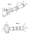
- FIG. 4 is a side perspective exploded view of a #1/1.5 bearing support structure with a multiple of jumper tubes mounted therein;
- the #1/1.5 bearing support structure 66 mounts to the fan inlet case 60 with fasteners 76 and to a # 1 seal support 78 with fasteners 80 such as a respective ring of bolts.
- the #-1/#1.5 bearing support structure 66 and the fan inlet case 60 may be manufactured as cast components with respective passages 82 , 84 that are integrally cast therein.
- the cast passages 82 , 84 provide for cooling, lubrication or other service pathways, but, being cast, may not be air or even fluid tight.
- a multiple of jumper tubes 88 are mounted within the #1/1.5 bearing support structure 66 ( FIG. 4 ) to provide a sealed services pathway between the passages 82 , 84 across an interface F 2 and the hollow struts 62 . That is, each jumper tube 88 provides an air or fluid tight services pathway within the the passages 82 , 84 across the interface F 2 to supply or remove various gaseous or liquid fluids.
- the jumper tubes 88 may also be utilized to guide wire harnesses or other conduits to and from the relatively remote front bearing compartment 38 - 1 .
- the jumper tubes 88 although illustrated as independent components in the disclosed non-limiting embodiment, may alternatively be integral to other structure such as the #1/1.5 bearing support structure 66 .
- the jumper tubes 88 may also facilitate “blind” assembly.
- the jumper tube 88 facilitates assembly of the gas turbine engine 20 and formation of sealed services pathways in communication with the forward bearing compartment 38 - 1 . That is, the jumper tube 88 may be assembled after the #1/1.5 bearing support structure 66 and # 1 bearing compartment 38 - 1 are mounted within the fan inlet case 60 .
- the jumper tubes 88 provide a continuous sealed services pathway through a multiple engine components, e.g., the #1/1.5 bearing support structure 66 and the fan inlet case 60 to provide service around the geared architecture 48 to and from the hollow strut 62 .
- the jumper tubes 88 also facilitate the assembly of the geared architecture 48 without resort to “blind assembly”.
Abstract
Description
Claims (18)
Priority Applications (4)
| Application Number | Priority Date | Filing Date | Title |
|---|---|---|---|
| US13/693,733 US9410447B2 (en) | 2012-07-30 | 2012-12-04 | Forward compartment service system for a geared architecture gas turbine engine |
| EP13824953.7A EP2880275B1 (en) | 2012-07-30 | 2013-07-30 | Forward compartment service system for a geared architecture gas turbine engine |
| PCT/US2013/052723 WO2014022392A1 (en) | 2012-07-30 | 2013-07-30 | Forward compartment service system for a geared architecture gas turbine engine |
| EP19174678.3A EP3543480A1 (en) | 2012-07-30 | 2013-07-30 | Forward compartment service system for a geared architecture gas turbine engine |
Applications Claiming Priority (2)
| Application Number | Priority Date | Filing Date | Title |
|---|---|---|---|
| US201261677284P | 2012-07-30 | 2012-07-30 | |
| US13/693,733 US9410447B2 (en) | 2012-07-30 | 2012-12-04 | Forward compartment service system for a geared architecture gas turbine engine |
Publications (2)
| Publication Number | Publication Date |
|---|---|
| US20140030088A1 US20140030088A1 (en) | 2014-01-30 |
| US9410447B2 true US9410447B2 (en) | 2016-08-09 |
Family
ID=49995065
Family Applications (1)
| Application Number | Title | Priority Date | Filing Date |
|---|---|---|---|
| US13/693,733 Active 2035-02-15 US9410447B2 (en) | 2012-07-30 | 2012-12-04 | Forward compartment service system for a geared architecture gas turbine engine |
Country Status (3)
| Country | Link |
|---|---|
| US (1) | US9410447B2 (en) |
| EP (2) | EP2880275B1 (en) |
| WO (1) | WO2014022392A1 (en) |
Cited By (3)
| Publication number | Priority date | Publication date | Assignee | Title |
|---|---|---|---|---|
| US20160363131A1 (en) * | 2015-02-16 | 2016-12-15 | United Technologies Corporation | Gas turbine engine front center body architecture |
| US20170176016A1 (en) * | 2015-12-21 | 2017-06-22 | General Electric Company | Combustor cap module and retention system therefor |
| US11371632B2 (en) | 2019-07-24 | 2022-06-28 | Raytheon Technologies Corporation | Compliant jumper tube fitting |
Families Citing this family (6)
| Publication number | Priority date | Publication date | Assignee | Title |
|---|---|---|---|---|
| WO2014152101A1 (en) | 2013-03-15 | 2014-09-25 | United Technologies Corporation | Turbofan engine bearing and gearbox arrangement |
| US10436113B2 (en) * | 2014-09-19 | 2019-10-08 | United Technologies Corporation | Plate for metering flow |
| US10161309B2 (en) | 2015-02-10 | 2018-12-25 | United Technologies Corporation | Thermally compliant fitting for high temperature tube applications |
| US11041438B2 (en) | 2016-04-06 | 2021-06-22 | General Electric Company | Gas turbine engine service tube mount |
| US10267334B2 (en) * | 2016-08-01 | 2019-04-23 | United Technologies Corporation | Annular heatshield |
| FR3086341B1 (en) | 2018-09-24 | 2020-11-27 | Safran Aircraft Engines | TURBOMACHINE WITH REDUCER FOR AN AIRCRAFT |
Citations (29)
| Publication number | Priority date | Publication date | Assignee | Title |
|---|---|---|---|---|
| US2875579A (en) * | 1952-08-08 | 1959-03-03 | Gen Motors Corp | Gas turbine engine midframe |
| US3110153A (en) * | 1950-09-05 | 1963-11-12 | Aerojet General Co | Gas generator turbojet motor |
| US4856273A (en) | 1988-07-21 | 1989-08-15 | General Motors Corporation | Secondary oil system for gas turbine engine |
| US4858426A (en) | 1988-07-21 | 1989-08-22 | General Motors Corporation | Secondary oil system for gas turbine engine |
| US4917218A (en) | 1989-04-03 | 1990-04-17 | General Motors Corporation | Secondary oil system for gas turbine engine |
| US5080555A (en) | 1990-11-16 | 1992-01-14 | General Motors Corporation | Turbine support for gas turbine engine |
| US5257903A (en) * | 1991-10-30 | 1993-11-02 | General Electric Company | Low pressure drop radial inflow air-oil separating arrangement and separator employed therein |
| US5782077A (en) * | 1995-05-15 | 1998-07-21 | Aerospatiale Societe Nationale Industrielle | Device for bleeding off and cooling hot air in an aircraft engine |
| US20050199445A1 (en) | 2004-03-09 | 2005-09-15 | Honeywell International Inc. | Apparatus and method for bearing lubrication in turbine engines |
| FR2896537A1 (en) | 2006-01-24 | 2007-07-27 | Snecma Sa | TURBOMACHINE WITH INTEGRATED GENERATOR-STARTER |
| US7266941B2 (en) | 2003-07-29 | 2007-09-11 | Pratt & Whitney Canada Corp. | Turbofan case and method of making |
| US7315228B2 (en) | 2003-11-06 | 2008-01-01 | Pratt & Whitney Canada Corp. | Electro-magnetically enhanced current interrupter |
| US20090110537A1 (en) | 2007-10-24 | 2009-04-30 | United Technologies Corp. | Gas Turbine Engine Systems Involving Integrated Fluid Conduits |
| EP2103780A2 (en) | 2008-03-21 | 2009-09-23 | United Technologies Corporation | Cold air buffer supply tube |
| US7721546B2 (en) | 2005-01-14 | 2010-05-25 | Pratt & Whitney Canada Corp. | Gas turbine internal manifold mounting arrangement |
| US7739866B2 (en) | 2003-07-29 | 2010-06-22 | Pratt & Whitney Canada Corp. | Turbofan case and method of making |
| US20100275572A1 (en) | 2009-04-30 | 2010-11-04 | Pratt & Whitney Canada Corp. | Oil line insulation system for mid turbine frame |
| US20100317478A1 (en) | 2009-06-10 | 2010-12-16 | United Technologies Corporation | Journal bearing with single unit jumper tube and filter |
| US7856830B2 (en) | 2006-05-26 | 2010-12-28 | Pratt & Whitney Canada Corp. | Noise reducing combustor |
| US7856825B2 (en) | 2007-05-16 | 2010-12-28 | Pratt & Whitney Canada Corp. | Redundant mounting system for an internal fuel manifold |
| US7856824B2 (en) * | 2007-06-25 | 2010-12-28 | Honeywell International Inc. | Cooling systems for use on aircraft |
| US7862293B2 (en) | 2007-05-03 | 2011-01-04 | Pratt & Whitney Canada Corp. | Low profile bleed air cooler |
| US20120011824A1 (en) | 2010-07-16 | 2012-01-19 | United Technologies Corporation | Integral lubrication tube and nozzle combination |
| US8171738B2 (en) | 2006-10-24 | 2012-05-08 | Pratt & Whitney Canada Corp. | Gas turbine internal manifold mounting arrangement |
| US20120121378A1 (en) | 2006-07-05 | 2012-05-17 | Sheridan William G | Oil baffle for gas turbine fan drive gear system |
| US8231142B2 (en) * | 2009-02-17 | 2012-07-31 | Pratt & Whitney Canada Corp. | Fluid conduit coupling with leakage detection |
| US8297917B1 (en) | 2011-06-08 | 2012-10-30 | United Technologies Corporation | Flexible support structure for a geared architecture gas turbine engine |
| EP2538036A2 (en) | 2011-06-24 | 2012-12-26 | United Technologies Corporation | Integral bearing support and centering spring assembly for a gas turbine engine |
| US8371127B2 (en) * | 2009-10-01 | 2013-02-12 | Pratt & Whitney Canada Corp. | Cooling air system for mid turbine frame |
Family Cites Families (1)
| Publication number | Priority date | Publication date | Assignee | Title |
|---|---|---|---|---|
| US8585538B2 (en) * | 2006-07-05 | 2013-11-19 | United Technologies Corporation | Coupling system for a star gear train in a gas turbine engine |
-
2012
- 2012-12-04 US US13/693,733 patent/US9410447B2/en active Active
-
2013
- 2013-07-30 WO PCT/US2013/052723 patent/WO2014022392A1/en active Application Filing
- 2013-07-30 EP EP13824953.7A patent/EP2880275B1/en active Active
- 2013-07-30 EP EP19174678.3A patent/EP3543480A1/en active Pending
Patent Citations (38)
| Publication number | Priority date | Publication date | Assignee | Title |
|---|---|---|---|---|
| US3110153A (en) * | 1950-09-05 | 1963-11-12 | Aerojet General Co | Gas generator turbojet motor |
| US2875579A (en) * | 1952-08-08 | 1959-03-03 | Gen Motors Corp | Gas turbine engine midframe |
| US4856273A (en) | 1988-07-21 | 1989-08-15 | General Motors Corporation | Secondary oil system for gas turbine engine |
| US4858426A (en) | 1988-07-21 | 1989-08-22 | General Motors Corporation | Secondary oil system for gas turbine engine |
| US4917218A (en) | 1989-04-03 | 1990-04-17 | General Motors Corporation | Secondary oil system for gas turbine engine |
| US5080555A (en) | 1990-11-16 | 1992-01-14 | General Motors Corporation | Turbine support for gas turbine engine |
| US5257903A (en) * | 1991-10-30 | 1993-11-02 | General Electric Company | Low pressure drop radial inflow air-oil separating arrangement and separator employed therein |
| US5782077A (en) * | 1995-05-15 | 1998-07-21 | Aerospatiale Societe Nationale Industrielle | Device for bleeding off and cooling hot air in an aircraft engine |
| US7370467B2 (en) | 2003-07-29 | 2008-05-13 | Pratt & Whitney Canada Corp. | Turbofan case and method of making |
| US7266941B2 (en) | 2003-07-29 | 2007-09-11 | Pratt & Whitney Canada Corp. | Turbofan case and method of making |
| US7765787B2 (en) | 2003-07-29 | 2010-08-03 | Pratt & Whitney Canada Corp. | Turbofan case and method of making |
| US7797922B2 (en) | 2003-07-29 | 2010-09-21 | Pratt & Whitney Canada Corp. | Gas turbine engine case and method of making |
| US7793488B2 (en) | 2003-07-29 | 2010-09-14 | Pratt & Whitney Canada Corp. | Turbofan case and method of making |
| US7770378B2 (en) | 2003-07-29 | 2010-08-10 | Pratt & Whitney Canada Corp. | Turbofan case and method of making |
| US7739866B2 (en) | 2003-07-29 | 2010-06-22 | Pratt & Whitney Canada Corp. | Turbofan case and method of making |
| US7315228B2 (en) | 2003-11-06 | 2008-01-01 | Pratt & Whitney Canada Corp. | Electro-magnetically enhanced current interrupter |
| US20050199445A1 (en) | 2004-03-09 | 2005-09-15 | Honeywell International Inc. | Apparatus and method for bearing lubrication in turbine engines |
| US7721546B2 (en) | 2005-01-14 | 2010-05-25 | Pratt & Whitney Canada Corp. | Gas turbine internal manifold mounting arrangement |
| FR2896537A1 (en) | 2006-01-24 | 2007-07-27 | Snecma Sa | TURBOMACHINE WITH INTEGRATED GENERATOR-STARTER |
| US7619331B2 (en) | 2006-01-24 | 2009-11-17 | Snecma | Turbomachine with integral generator/starter |
| US7856830B2 (en) | 2006-05-26 | 2010-12-28 | Pratt & Whitney Canada Corp. | Noise reducing combustor |
| US20120121378A1 (en) | 2006-07-05 | 2012-05-17 | Sheridan William G | Oil baffle for gas turbine fan drive gear system |
| US8171738B2 (en) | 2006-10-24 | 2012-05-08 | Pratt & Whitney Canada Corp. | Gas turbine internal manifold mounting arrangement |
| US7862293B2 (en) | 2007-05-03 | 2011-01-04 | Pratt & Whitney Canada Corp. | Low profile bleed air cooler |
| US7856825B2 (en) | 2007-05-16 | 2010-12-28 | Pratt & Whitney Canada Corp. | Redundant mounting system for an internal fuel manifold |
| US7856824B2 (en) * | 2007-06-25 | 2010-12-28 | Honeywell International Inc. | Cooling systems for use on aircraft |
| US20090110537A1 (en) | 2007-10-24 | 2009-04-30 | United Technologies Corp. | Gas Turbine Engine Systems Involving Integrated Fluid Conduits |
| EP2103780A2 (en) | 2008-03-21 | 2009-09-23 | United Technologies Corporation | Cold air buffer supply tube |
| US8240974B2 (en) | 2008-03-21 | 2012-08-14 | United Technologies Corporation | Cold air buffer supply tube |
| US8231142B2 (en) * | 2009-02-17 | 2012-07-31 | Pratt & Whitney Canada Corp. | Fluid conduit coupling with leakage detection |
| US20100275572A1 (en) | 2009-04-30 | 2010-11-04 | Pratt & Whitney Canada Corp. | Oil line insulation system for mid turbine frame |
| US20100317478A1 (en) | 2009-06-10 | 2010-12-16 | United Technologies Corporation | Journal bearing with single unit jumper tube and filter |
| US8371127B2 (en) * | 2009-10-01 | 2013-02-12 | Pratt & Whitney Canada Corp. | Cooling air system for mid turbine frame |
| US20120011824A1 (en) | 2010-07-16 | 2012-01-19 | United Technologies Corporation | Integral lubrication tube and nozzle combination |
| US8297917B1 (en) | 2011-06-08 | 2012-10-30 | United Technologies Corporation | Flexible support structure for a geared architecture gas turbine engine |
| US8297916B1 (en) | 2011-06-08 | 2012-10-30 | United Technologies Corporation | Flexible support structure for a geared architecture gas turbine engine |
| EP2538036A2 (en) | 2011-06-24 | 2012-12-26 | United Technologies Corporation | Integral bearing support and centering spring assembly for a gas turbine engine |
| US8834095B2 (en) | 2011-06-24 | 2014-09-16 | United Technologies Corporation | Integral bearing support and centering spring assembly for a gas turbine engine |
Non-Patent Citations (1)
| Title |
|---|
| International search report for PCT/US2013/052723 dated Oct. 25, 2013. |
Cited By (6)
| Publication number | Priority date | Publication date | Assignee | Title |
|---|---|---|---|---|
| US20160363131A1 (en) * | 2015-02-16 | 2016-12-15 | United Technologies Corporation | Gas turbine engine front center body architecture |
| US10100843B2 (en) * | 2015-02-16 | 2018-10-16 | United Technologies Corporation | Gas turbine engine front center body architecture |
| US10935048B2 (en) * | 2015-02-16 | 2021-03-02 | Raytheon Technologies Corporation | Gas turbine engine front center body architecture |
| US20170176016A1 (en) * | 2015-12-21 | 2017-06-22 | General Electric Company | Combustor cap module and retention system therefor |
| US10429073B2 (en) * | 2015-12-21 | 2019-10-01 | General Electric Company | Combustor cap module and retention system therefor |
| US11371632B2 (en) | 2019-07-24 | 2022-06-28 | Raytheon Technologies Corporation | Compliant jumper tube fitting |
Also Published As
| Publication number | Publication date |
|---|---|
| WO2014022392A1 (en) | 2014-02-06 |
| EP2880275A4 (en) | 2015-08-26 |
| EP3543480A1 (en) | 2019-09-25 |
| US20140030088A1 (en) | 2014-01-30 |
| EP2880275B1 (en) | 2019-05-29 |
| EP2880275A1 (en) | 2015-06-10 |
Similar Documents
| Publication | Publication Date | Title |
|---|---|---|
| US9410447B2 (en) | Forward compartment service system for a geared architecture gas turbine engine | |
| US11365648B2 (en) | Integral gutter and front center body | |
| EP3553295A1 (en) | Thermal management of tail cone mounted generator | |
| US8366382B1 (en) | Mid-turbine frame buffer system | |
| US11486269B2 (en) | Gas turbine engine shaft bearing configuration | |
| US10094286B2 (en) | Gas turbine engine with lower bifurcation heat exchanger | |
| EP2971663B1 (en) | Oil transfer passage arrangement for a shaft of a gas turbine engine | |
| EP2900998B1 (en) | Buffer airflow to bearing compartment | |
| US9896968B2 (en) | Forward compartment baffle arrangement for a geared turbofan engine | |
| US11339723B2 (en) | Geared turbofan high gearbox power density | |
| US20130192240A1 (en) | Buffer system for a gas turbine engine | |
| US20150240662A1 (en) | Case assembly for a gas turbine engine | |
| EP3550126B1 (en) | Geared gas turbine engine with improved breather air venting | |
| US10378440B2 (en) | Geared turbofan with improved gear system maintainability | |
| EP4074952A1 (en) | Geared gas turbine with oil scavenge ejector pump assist |
Legal Events
| Date | Code | Title | Description |
|---|---|---|---|
| AS | Assignment |
Owner name: UNITED TECHNOLOGIES CORPORATION, CONNECTICUT Free format text: ASSIGNMENT OF ASSIGNORS INTEREST;ASSIGNORS:COFFIN, JAMES B.;DAVIS, TODD A.;DIBENEDETTO, ENZO;SIGNING DATES FROM 20121129 TO 20121203;REEL/FRAME:029402/0816 |
|
| STCF | Information on status: patent grant |
Free format text: PATENTED CASE |
|
| MAFP | Maintenance fee payment |
Free format text: PAYMENT OF MAINTENANCE FEE, 4TH YEAR, LARGE ENTITY (ORIGINAL EVENT CODE: M1551); ENTITY STATUS OF PATENT OWNER: LARGE ENTITY Year of fee payment: 4 |
|
| AS | Assignment |
Owner name: RAYTHEON TECHNOLOGIES CORPORATION, MASSACHUSETTS Free format text: CHANGE OF NAME;ASSIGNOR:UNITED TECHNOLOGIES CORPORATION;REEL/FRAME:054062/0001 Effective date: 20200403 |
|
| AS | Assignment |
Owner name: RAYTHEON TECHNOLOGIES CORPORATION, CONNECTICUT Free format text: CORRECTIVE ASSIGNMENT TO CORRECT THE AND REMOVE PATENT APPLICATION NUMBER 11886281 AND ADD PATENT APPLICATION NUMBER 14846874. TO CORRECT THE RECEIVING PARTY ADDRESS PREVIOUSLY RECORDED AT REEL: 054062 FRAME: 0001. ASSIGNOR(S) HEREBY CONFIRMS THE CHANGE OF ADDRESS;ASSIGNOR:UNITED TECHNOLOGIES CORPORATION;REEL/FRAME:055659/0001 Effective date: 20200403 |
|
| AS | Assignment |
Owner name: RTX CORPORATION, CONNECTICUT Free format text: CHANGE OF NAME;ASSIGNOR:RAYTHEON TECHNOLOGIES CORPORATION;REEL/FRAME:064714/0001 Effective date: 20230714 |
|
| MAFP | Maintenance fee payment |
Free format text: PAYMENT OF MAINTENANCE FEE, 8TH YEAR, LARGE ENTITY (ORIGINAL EVENT CODE: M1552); ENTITY STATUS OF PATENT OWNER: LARGE ENTITY Year of fee payment: 8 |