EP3084181B1 - Geared turbofan with improved gear system maintainability - Google Patents
Geared turbofan with improved gear system maintainability Download PDFInfo
- Publication number
- EP3084181B1 EP3084181B1 EP14872784.5A EP14872784A EP3084181B1 EP 3084181 B1 EP3084181 B1 EP 3084181B1 EP 14872784 A EP14872784 A EP 14872784A EP 3084181 B1 EP3084181 B1 EP 3084181B1
- Authority
- EP
- European Patent Office
- Prior art keywords
- hub
- geared architecture
- recited
- gas turbine
- engine
- Prior art date
- Legal status (The legal status is an assumption and is not a legal conclusion. Google has not performed a legal analysis and makes no representation as to the accuracy of the status listed.)
- Active
Links
- 238000000034 method Methods 0.000 claims description 19
- 239000000314 lubricant Substances 0.000 claims description 16
- 230000003068 static effect Effects 0.000 claims description 15
- 230000009467 reduction Effects 0.000 claims description 14
- 239000000446 fuel Substances 0.000 description 5
- 238000012423 maintenance Methods 0.000 description 5
- 238000007689 inspection Methods 0.000 description 4
- 238000004891 communication Methods 0.000 description 2
- 230000004323 axial length Effects 0.000 description 1
- 230000008859 change Effects 0.000 description 1
- 238000002485 combustion reaction Methods 0.000 description 1
- 230000006835 compression Effects 0.000 description 1
- 238000007906 compression Methods 0.000 description 1
- 238000012937 correction Methods 0.000 description 1
- 230000007246 mechanism Effects 0.000 description 1
- 238000012986 modification Methods 0.000 description 1
- 230000004048 modification Effects 0.000 description 1
- 239000010705 motor oil Substances 0.000 description 1
- 230000001141 propulsive effect Effects 0.000 description 1
- 230000004044 response Effects 0.000 description 1
- 238000004904 shortening Methods 0.000 description 1
- 238000012546 transfer Methods 0.000 description 1
Images


Classifications
-
- F—MECHANICAL ENGINEERING; LIGHTING; HEATING; WEAPONS; BLASTING
- F02—COMBUSTION ENGINES; HOT-GAS OR COMBUSTION-PRODUCT ENGINE PLANTS
- F02C—GAS-TURBINE PLANTS; AIR INTAKES FOR JET-PROPULSION PLANTS; CONTROLLING FUEL SUPPLY IN AIR-BREATHING JET-PROPULSION PLANTS
- F02C3/00—Gas-turbine plants characterised by the use of combustion products as the working fluid
- F02C3/04—Gas-turbine plants characterised by the use of combustion products as the working fluid having a turbine driving a compressor
- F02C3/107—Gas-turbine plants characterised by the use of combustion products as the working fluid having a turbine driving a compressor with two or more rotors connected by power transmission
- F02C3/113—Gas-turbine plants characterised by the use of combustion products as the working fluid having a turbine driving a compressor with two or more rotors connected by power transmission with variable power transmission between rotors
-
- F—MECHANICAL ENGINEERING; LIGHTING; HEATING; WEAPONS; BLASTING
- F01—MACHINES OR ENGINES IN GENERAL; ENGINE PLANTS IN GENERAL; STEAM ENGINES
- F01D—NON-POSITIVE DISPLACEMENT MACHINES OR ENGINES, e.g. STEAM TURBINES
- F01D25/00—Component parts, details, or accessories, not provided for in, or of interest apart from, other groups
- F01D25/16—Arrangement of bearings; Supporting or mounting bearings in casings
-
- F—MECHANICAL ENGINEERING; LIGHTING; HEATING; WEAPONS; BLASTING
- F02—COMBUSTION ENGINES; HOT-GAS OR COMBUSTION-PRODUCT ENGINE PLANTS
- F02C—GAS-TURBINE PLANTS; AIR INTAKES FOR JET-PROPULSION PLANTS; CONTROLLING FUEL SUPPLY IN AIR-BREATHING JET-PROPULSION PLANTS
- F02C3/00—Gas-turbine plants characterised by the use of combustion products as the working fluid
- F02C3/04—Gas-turbine plants characterised by the use of combustion products as the working fluid having a turbine driving a compressor
- F02C3/107—Gas-turbine plants characterised by the use of combustion products as the working fluid having a turbine driving a compressor with two or more rotors connected by power transmission
-
- F—MECHANICAL ENGINEERING; LIGHTING; HEATING; WEAPONS; BLASTING
- F02—COMBUSTION ENGINES; HOT-GAS OR COMBUSTION-PRODUCT ENGINE PLANTS
- F02C—GAS-TURBINE PLANTS; AIR INTAKES FOR JET-PROPULSION PLANTS; CONTROLLING FUEL SUPPLY IN AIR-BREATHING JET-PROPULSION PLANTS
- F02C7/00—Features, components parts, details or accessories, not provided for in, or of interest apart form groups F02C1/00 - F02C6/00; Air intakes for jet-propulsion plants
- F02C7/06—Arrangements of bearings; Lubricating
-
- F—MECHANICAL ENGINEERING; LIGHTING; HEATING; WEAPONS; BLASTING
- F02—COMBUSTION ENGINES; HOT-GAS OR COMBUSTION-PRODUCT ENGINE PLANTS
- F02C—GAS-TURBINE PLANTS; AIR INTAKES FOR JET-PROPULSION PLANTS; CONTROLLING FUEL SUPPLY IN AIR-BREATHING JET-PROPULSION PLANTS
- F02C7/00—Features, components parts, details or accessories, not provided for in, or of interest apart form groups F02C1/00 - F02C6/00; Air intakes for jet-propulsion plants
- F02C7/36—Power transmission arrangements between the different shafts of the gas turbine plant, or between the gas-turbine plant and the power user
-
- F—MECHANICAL ENGINEERING; LIGHTING; HEATING; WEAPONS; BLASTING
- F02—COMBUSTION ENGINES; HOT-GAS OR COMBUSTION-PRODUCT ENGINE PLANTS
- F02K—JET-PROPULSION PLANTS
- F02K3/00—Plants including a gas turbine driving a compressor or a ducted fan
- F02K3/02—Plants including a gas turbine driving a compressor or a ducted fan in which part of the working fluid by-passes the turbine and combustion chamber
- F02K3/04—Plants including a gas turbine driving a compressor or a ducted fan in which part of the working fluid by-passes the turbine and combustion chamber the plant including ducted fans, i.e. fans with high volume, low pressure outputs, for augmenting the jet thrust, e.g. of double-flow type
- F02K3/06—Plants including a gas turbine driving a compressor or a ducted fan in which part of the working fluid by-passes the turbine and combustion chamber the plant including ducted fans, i.e. fans with high volume, low pressure outputs, for augmenting the jet thrust, e.g. of double-flow type with front fan
-
- F—MECHANICAL ENGINEERING; LIGHTING; HEATING; WEAPONS; BLASTING
- F05—INDEXING SCHEMES RELATING TO ENGINES OR PUMPS IN VARIOUS SUBCLASSES OF CLASSES F01-F04
- F05D—INDEXING SCHEME FOR ASPECTS RELATING TO NON-POSITIVE-DISPLACEMENT MACHINES OR ENGINES, GAS-TURBINES OR JET-PROPULSION PLANTS
- F05D2220/00—Application
- F05D2220/30—Application in turbines
- F05D2220/32—Application in turbines in gas turbines
- F05D2220/323—Application in turbines in gas turbines for aircraft propulsion, e.g. jet engines
-
- F—MECHANICAL ENGINEERING; LIGHTING; HEATING; WEAPONS; BLASTING
- F05—INDEXING SCHEMES RELATING TO ENGINES OR PUMPS IN VARIOUS SUBCLASSES OF CLASSES F01-F04
- F05D—INDEXING SCHEME FOR ASPECTS RELATING TO NON-POSITIVE-DISPLACEMENT MACHINES OR ENGINES, GAS-TURBINES OR JET-PROPULSION PLANTS
- F05D2230/00—Manufacture
- F05D2230/70—Disassembly methods
-
- F—MECHANICAL ENGINEERING; LIGHTING; HEATING; WEAPONS; BLASTING
- F05—INDEXING SCHEMES RELATING TO ENGINES OR PUMPS IN VARIOUS SUBCLASSES OF CLASSES F01-F04
- F05D—INDEXING SCHEME FOR ASPECTS RELATING TO NON-POSITIVE-DISPLACEMENT MACHINES OR ENGINES, GAS-TURBINES OR JET-PROPULSION PLANTS
- F05D2230/00—Manufacture
- F05D2230/72—Maintenance
-
- F—MECHANICAL ENGINEERING; LIGHTING; HEATING; WEAPONS; BLASTING
- F05—INDEXING SCHEMES RELATING TO ENGINES OR PUMPS IN VARIOUS SUBCLASSES OF CLASSES F01-F04
- F05D—INDEXING SCHEME FOR ASPECTS RELATING TO NON-POSITIVE-DISPLACEMENT MACHINES OR ENGINES, GAS-TURBINES OR JET-PROPULSION PLANTS
- F05D2240/00—Components
- F05D2240/35—Combustors or associated equipment
-
- F—MECHANICAL ENGINEERING; LIGHTING; HEATING; WEAPONS; BLASTING
- F05—INDEXING SCHEMES RELATING TO ENGINES OR PUMPS IN VARIOUS SUBCLASSES OF CLASSES F01-F04
- F05D—INDEXING SCHEME FOR ASPECTS RELATING TO NON-POSITIVE-DISPLACEMENT MACHINES OR ENGINES, GAS-TURBINES OR JET-PROPULSION PLANTS
- F05D2260/00—Function
- F05D2260/40—Transmission of power
- F05D2260/403—Transmission of power through the shape of the drive components
- F05D2260/4031—Transmission of power through the shape of the drive components as in toothed gearing
Definitions
- a gas turbine engine typically includes a fan section, a compressor section, a combustor section and a turbine section. Air entering the compressor section is compressed and delivered into the combustion section where it is mixed with fuel and ignited to generate a high-speed exhaust gas flow. The high-speed exhaust gas flow expands through the turbine section to drive the compressor and the fan section.
- a speed reduction device such as an epicyclical gear assembly may be utilized to drive the fan section such that the fan section may rotate at a speed different than the turbine section so as to increase the overall propulsive efficiency of the engine.
- a shaft driven by one of the turbine sections provides an input to the epicyclical gear assembly that drives the fan section at a reduced speed such that both the turbine section and the fan section can rotate at closer to optimal speeds.
- a gas turbine engine having the features of the preamble of claim 1 is disclosed in US 2012/0099988 A1 or US 4934140 A .
- US 4704862 A discloses a ducted prop engine
- US 2008/0120839 A1 discloses a turbofan engine assembly and method of assembling same.
- the invention provides a gas turbine engine as set forth in claim 1.
- the bearing assembly includes an inner race supported by a static structure and an outer race supporting rotation of the hub.
- the outer race is disposed radially outward of the inner race and the hub is directly supported for rotation on the outer race.
- any of the foregoing gas turbine engines includes a rotating gutter disposed radially outside the speed reduction device for collecting lubricant and directing lubricant to a lubricant supply system.
- the speed reduction device includes a star gear system including a ring gear fixed for rotation with the hub.
- the star gear system includes a carrier supporting a plurality of intermediate gears fixed to a static engine structure.
- the speed reduction device includes a planetary gear system including a carrier supporting a plurality of intermediate gears.
- the carrier is fixed for rotation with the hub.
- the planetary gear system includes a ring gear circumscribing the intermediate gears.
- the ring gear is fixed to a static engine structure.
- the speed reduction device is removable without removal of the fan section.
- the invention also provides a method of removing a geared architecture from a gas turbine engine, as set forth in claim 8.
- An embodiment of the foregoing method includes decoupling a portion of the geared architecture from the fan section.
- the step of decoupling the geared architecture includes decoupling intermediate gears from a ring gear fixed to the hub.
- decoupling the geared architecture includes decoupling a carrier supporting a plurality of intermediate gears from the fixed engine structure.
- decoupling the geared architecture includes decoupling the carrier supporting a plurality of intermediate gears from the hub.
- a further embodiment of any of the foregoing methods includes removing a nose cone attached to a hub of the fan section to provide access to the geared architecture.
- the hub remains supported by the bearing assembly upon removal of the geared architecture.
- removing of the geared architecture includes moving the geared architecture along the axis forward of the fan section.
- FIG. 1 schematically illustrates a gas turbine engine 20.
- the gas turbine engine 20 is disclosed herein as a two-spool turbofan that generally incorporates a fan section 22 and a gas generator 25.
- the gas generator 25 includes a compressor section 24, a combustor section 26 and a turbine section 28.
- Alternative engines might include an augmentor section (not shown) among other systems or features.
- the fan section 22 drives air along a bypass flow path B in a bypass duct defined within a nacelle 15, while the compressor section 24 drives air along a core flow path C for compression and communication into the combustor section 26 then expansion through the turbine section 28.
- the exemplary engine 20 generally includes a low speed spool 30 and a high speed spool 32 mounted for rotation about an engine central longitudinal axis A relative to an engine static structure 36 via several bearing systems 38. It should be understood that various bearing systems 38 at various locations may alternatively or additionally be provided and the location of bearing systems 38 may be varied as appropriate to the application.
- the low speed spool 30 generally includes an inner shaft 40 that interconnects a fan 42, a first (or low) pressure compressor 44 and a first (or low) pressure turbine 46.
- the inner shaft 40 is connected to the fan 42 through a speed change mechanism, which in exemplary gas turbine engine 20 is illustrated as a geared architecture 48 to drive the fan 42 at a lower speed than the low speed spool 30.
- the high speed spool 32 includes an outer shaft 50 that interconnects a second (or high) pressure compressor 52 and a second (or high) pressure turbine 54.
- a combustor 56 is arranged in exemplary gas turbine 20 between the high pressure compressor 52 and the high pressure turbine 54.
- a mid-turbine frame 58 of the engine static structure 36 is arranged generally between the high pressure turbine 54 and the low pressure turbine 46.
- the mid-turbine frame 58 further supports bearing systems 38 in the turbine section 28.
- the inner shaft 40 and the outer shaft 50 are concentric and rotate via bearing systems 38 about the engine central longitudinal axis A which is collinear with their longitudinal axes.
- the core airflow is compressed by the low pressure compressor 44 then the high pressure compressor 52, mixed and burned with fuel in the combustor 56, then expanded over the high pressure turbine 54 and low pressure turbine 46.
- the mid-turbine frame 58 includes airfoils 60 which are in the core airflow path C.
- the turbines 46, 54 rotationally drive the respective low speed spool 30 and high speed spool 32 in response to the expansion.
- the engine 20 in one example is a high-bypass geared aircraft engine.
- the engine 20 bypass ratio is greater than about six (6), with an example embodiment being greater than about ten (10)
- the geared architecture 48 is an epicyclic gear train, such as a planetary gear system or other gear system, with a gear reduction ratio of greater than about 2.3
- the low pressure turbine 46 has a pressure ratio that is greater than about five.
- the engine 20 bypass ratio is greater than about ten (10:1)
- the fan diameter is significantly larger than that of the low pressure compressor 44
- the low pressure turbine 46 has a pressure ratio that is greater than about five 5:1.
- Low pressure turbine 46 pressure ratio is pressure measured prior to inlet of low pressure turbine 46 as related to the pressure at the outlet of the low pressure turbine 46 prior to an exhaust nozzle.
- the geared architecture 48 may be an epicycle gear train, such as a planetary gear system or other gear system, with a gear reduction ratio of greater than about 2.3:1. It should be understood, however, that the above parameters are only exemplary of one embodiment of a geared architecture engine and that the present invention is applicable to other gas turbine engines including direct drive turbofans.
- the fan section 22 of the engine 20 is designed for a particular flight condition -- typically cruise at about 0.8 Mach and about 35,000 feet (10668 m).
- "Low fan pressure ratio” is the pressure ratio across the fan blade alone, without a Fan Exit Guide Vane (“FEGV”) system.
- the low fan pressure ratio as disclosed herein according to one non-limiting embodiment is less than about 1.45.
- the "Low corrected fan tip speed" as disclosed herein according to one non-limiting embodiment is less than about 1150 ft / second (350.5 m/s).
- the example gas turbine engine includes the fan 42 that comprises in one non-limiting embodiment less than about twenty-six (26) fan blades. In another non-limiting embodiment, the fan section 22 includes less than about twenty (20) fan blades. Moreover, in one disclosed embodiment the low pressure turbine 46 includes no more than about six (6) turbine rotors schematically indicated at 34. In another non-limiting example embodiment the low pressure turbine 46 includes about three (3) turbine rotors. A ratio between the number of fan blades 42 and the number of low pressure turbine rotors is between about 3.3 and about 8.6.
- the example low pressure turbine 46 can also be referred to as a fan drive turbine and provides the driving power to rotate the fan section 22 and therefore the relationship between the number of turbine rotors 34 in the low pressure turbine 46 and the number of blades 42 in the fan section 22 disclose an example gas turbine engine 20 with increased power transfer efficiency.
- the example fan section 22 includes a hub 62 that supports the plurality of fan blades 42.
- the hub 62 is supported on a bearing assembly 64.
- the example geared architecture 48 is disposed forward of the bearing assembly 64 to facilitate easy access and removal from the gas turbine engine without removal of the entire fan section 22.
- the example fan section 22 includes the geared architecture 48 that is disposed radially within the hub 62 supporting the plurality of fan blades 42.
- the hub 62 is supported for rotation by bearing assembly 64.
- the bearing assembly 64 includes an outer race 66 and an inner race 68 that is disposed between roller bearings 65.
- the outer race 66 may be an integral part portion of the hub 62 or may be attached to the hub 62 to rotate with the hub 62.
- the example geared architecture 48 is supported forward of the bearing assembly 64 and includes a sun gear 74 that is driven by the inner shaft 40.
- the inner shaft 40 includes a flexible portion 45 that is disposed just rearward of the sun gear 74 to provide flexibility to aid alignment of the geared architecture 48.
- the example geared architecture 48 is referred to as a star system.
- a sun gear 74 is driven by the shaft 40 and rotates intermediate gear 76 that is supported within a carrier 80.
- the carrier 80 is fixed to the engine static structure 36.
- the plurality of intermediate gears 76 are circumscribed by a ring gear 78.
- the example ring gear 78 is fixed to the hub 62 to generate rotation of the hub 62 and thereby the plurality of fan blades 42 about the axis A.
- the geared architecture 48 is disposed radially inward and axially within the hub 62.
- the example geared architecture 48 disposed within the hub 62 enables shortening of the engine such that the geared architecture 48 does not create additional axial length in addition to the hub 62.
- the geared architecture 48 is disposed within the hub and a cover 72 is attached to the hub to cover the geared architecture 48.
- a nose cone 70 is further attached to the hub to provide the desired aerodynamic flow through the fan section 42.
- the example hub 62 includes an integral lubricant gutter 82 that collects lubricant exiting the geared architecture 48.
- the gutter 82 captures lubricant 88 that flung outward from the geared architecture 48.
- the hub 62 includes passages 90 that direct lubricant flow 88 into an intermediate cavity 94 formed within the static structure 36 of the engine.
- the intermediate cavity 94 includes an opening 98 that provides for the communication of lubricant 80 to an engine lubricant sump 92.
- the lubricant sump 92 is illustrated schematically and can include other features that accumulate lubricant and circulate that lubricant back to the lubricant system of the gas turbine engine.
- another fan section 22' as illustrated includes a geared architecture 48' that is also supported within the hub 62.
- the geared architecture 48 comprises a planetary system where a ring gear 86 is fixed to the engine static structure 36 and a carrier 84 that supports rotation of the intermediate gear 76 is fixed to the rotating hub 62.
- the inner shaft 40 drives the sun gear 74 which in turn drives intermediate gears 76.
- Intermediate gears 76 are supported within the carrier 84.
- Carrier 84 is in turn fixed to the hub 62 such that rotation of the carrier 84 is transmitted to the hub 62 to rotate the plurality of blades 42 about the axis A.
- the different configurations of the geared architecture 48 and 48' enable desired gear ratios to drive the fan section 22 at a speed that provides efficient fan operation.
- the example geared architecture 48 is mounted forward of the bearing assembly 64 and is therefore removable without removing additional engine structures.
- the geared architecture 48 is accessed by first removing a nose cone 70 and then a cover 72.
- the nose cone 70 and the cover 72 can be removed from the hub 62 without disturbing other features of the fan section 22.
- the geared architecture 48 is then decoupled from the inner shaft 40 and is therefore also removable forward through the opening provided upon removal of the cover 72 and the nose cone 70.
- the example geared architecture 48 in this example, is decoupled from the ring gear 78 that is formed as a portion connected to the hub 62. The remaining portions of the geared architecture 48 including the sun gear and the carrier 80 are then removed axially forward along the axis A out of the hub 62 without removal of the hub 62 from the engine structure.
- the disclosed location of the geared architecture 48 allows for removal without disturbing the fan hub 62 and therefore allows for removal of the geared architecture 48 when the engine is still mounted to an aircraft.
- a disclosed method of removal includes removing the nose cone and cover 72 and accessing the geared architecture 48. Once access is obtained through the forward portion of the engine to the geared architecture 48, the geared architecture 48 is decoupled from any fixed structures of the engine. In this example, the carrier 80 is fixed to a static structure 36 of the engine and therefore is decoupled by removing fasteners or other attachment means and devices that fix and secure the carrier 80 to the fixed static structure 36. The remaining portions of the geared architecture 48 are then removed from engagement to the shaft 40 and the ring gear 78. Accordingly, the geared architecture 48 may then be removed from a forward portion of the fan section 22.
- the planetary configuration can be removed in essentially the same manner as a star system.
- the removal steps will include decoupling of the carrier 84 from the hub structure 62 and decoupling of the ring gear 86 from the engine static structure 36 to enable access and removal of the gear assembly 48'.
- the example geared architecture mounting structure enables access and removal of the geared architecture while the engine is still supported on the aircraft.
- the ability to access, inspect and remove the geared architecture while the engine is still on the aircraft reduces maintenance and inspection time and, thereby, increases maintenance efficiency and reduces cost.
Description
- A gas turbine engine typically includes a fan section, a compressor section, a combustor section and a turbine section. Air entering the compressor section is compressed and delivered into the combustion section where it is mixed with fuel and ignited to generate a high-speed exhaust gas flow. The high-speed exhaust gas flow expands through the turbine section to drive the compressor and the fan section.
- A speed reduction device such as an epicyclical gear assembly may be utilized to drive the fan section such that the fan section may rotate at a speed different than the turbine section so as to increase the overall propulsive efficiency of the engine. In such engine architectures, a shaft driven by one of the turbine sections provides an input to the epicyclical gear assembly that drives the fan section at a reduced speed such that both the turbine section and the fan section can rotate at closer to optimal speeds.
- Access to the gear assembly is required to facilitate inspection and maintenance. Inspection and maintenance of a turbine engine requires significant time and expense. Accordingly, engine manufactures continually seek methods and configurations that reduce time and expense corresponding to inspection and maintenance.
- A gas turbine engine having the features of the preamble of claim 1 is disclosed in
US 2012/0099988 A1 orUS 4934140 A . -
US 4704862 A discloses a ducted prop engine, andUS 2008/0120839 A1 discloses a turbofan engine assembly and method of assembling same. - From a first aspect, the invention provides a gas turbine engine as set forth in claim 1.
- In an embodiment of the foregoing gas turbine engine, the bearing assembly includes an inner race supported by a static structure and an outer race supporting rotation of the hub.
- In an embodiment of the foregoing gas turbine engine, the outer race is disposed radially outward of the inner race and the hub is directly supported for rotation on the outer race.
- In a further embodiment of any of the foregoing gas turbine engines, includes a rotating gutter disposed radially outside the speed reduction device for collecting lubricant and directing lubricant to a lubricant supply system.
- In a further embodiment of any of the foregoing gas turbine engines, the speed reduction device includes a star gear system including a ring gear fixed for rotation with the hub.
- In an embodiment of the foregoing gas turbine engine, the star gear system includes a carrier supporting a plurality of intermediate gears fixed to a static engine structure.
- In an alternative embodiment, the speed reduction device includes a planetary gear system including a carrier supporting a plurality of intermediate gears. The carrier is fixed for rotation with the hub.
- In an embodiment of the foregoing gas turbine engine, the planetary gear system includes a ring gear circumscribing the intermediate gears. The ring gear is fixed to a static engine structure.
- In a further embodiment of any of the foregoing gas turbine engines, the speed reduction device is removable without removal of the fan section.
- The invention also provides a method of removing a geared architecture from a gas turbine engine, as set forth in claim 8.
- An embodiment of the foregoing method includes decoupling a portion of the geared architecture from the fan section.
- In a further embodiment of any of the foregoing methods, the step of decoupling the geared architecture includes decoupling intermediate gears from a ring gear fixed to the hub.
- In a further embodiment of any of the foregoing method, decoupling the geared architecture includes decoupling a carrier supporting a plurality of intermediate gears from the fixed engine structure.
- In an alternative embodiment, decoupling the geared architecture includes decoupling the carrier supporting a plurality of intermediate gears from the hub.
- In a further embodiment of any of the foregoing methods, includes decoupling a sun gear of the geared architecture from a shaft.
- A further embodiment of any of the foregoing methods includes removing a nose cone attached to a hub of the fan section to provide access to the geared architecture.
- In a further embodiment of any of the foregoing methods, the hub remains supported by the bearing assembly upon removal of the geared architecture.
- In a further embodiment of any of the foregoing methods, removing of the geared architecture includes moving the geared architecture along the axis forward of the fan section.
- Although the different examples have the specific components shown in the illustrations, embodiments of this disclosure are not limited to those particular combinations.
- These and other features disclosed herein can be best understood from the following specification and drawings, the following of which is a brief description.
-
-
Figure 1 is a schematic view of an example gas turbine engine. -
Figure 2 is a schematic view of a fan section of an example gas turbine engine. -
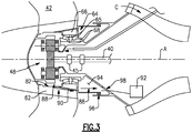
Figure 3 is an enlarged view of lubricant flow through the fan section of the example gas turbine engine. -
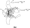
Figure 4 is another embodiment of a fan section of an example gas turbine engine. -
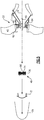
Figure 5 is a schematic illustration of a disassembly of a geared architecture from the example gas turbine engine. -
Figure 1 schematically illustrates agas turbine engine 20. Thegas turbine engine 20 is disclosed herein as a two-spool turbofan that generally incorporates afan section 22 and a gas generator 25. In this example the gas generator 25 includes acompressor section 24, acombustor section 26 and aturbine section 28. Alternative engines might include an augmentor section (not shown) among other systems or features. Thefan section 22 drives air along a bypass flow path B in a bypass duct defined within a nacelle 15, while thecompressor section 24 drives air along a core flow path C for compression and communication into thecombustor section 26 then expansion through theturbine section 28. Although depicted as a two-spool turbofan gas turbine engine in the disclosed non-limiting embodiment, it should be understood that the concepts described herein are not limited to use with two-spool turbofans as the teachings may be applied to other types of turbine engines including three-spool architectures. - The
exemplary engine 20 generally includes alow speed spool 30 and ahigh speed spool 32 mounted for rotation about an engine central longitudinal axis A relative to an enginestatic structure 36 viaseveral bearing systems 38. It should be understood thatvarious bearing systems 38 at various locations may alternatively or additionally be provided and the location ofbearing systems 38 may be varied as appropriate to the application. - The
low speed spool 30 generally includes aninner shaft 40 that interconnects afan 42, a first (or low)pressure compressor 44 and a first (or low)pressure turbine 46. Theinner shaft 40 is connected to thefan 42 through a speed change mechanism, which in exemplarygas turbine engine 20 is illustrated as a gearedarchitecture 48 to drive thefan 42 at a lower speed than thelow speed spool 30. Thehigh speed spool 32 includes anouter shaft 50 that interconnects a second (or high)pressure compressor 52 and a second (or high)pressure turbine 54. Acombustor 56 is arranged inexemplary gas turbine 20 between thehigh pressure compressor 52 and thehigh pressure turbine 54. Amid-turbine frame 58 of the enginestatic structure 36 is arranged generally between thehigh pressure turbine 54 and thelow pressure turbine 46. Themid-turbine frame 58 further supports bearingsystems 38 in theturbine section 28. Theinner shaft 40 and theouter shaft 50 are concentric and rotate viabearing systems 38 about the engine central longitudinal axis A which is collinear with their longitudinal axes. - The core airflow is compressed by the
low pressure compressor 44 then thehigh pressure compressor 52, mixed and burned with fuel in thecombustor 56, then expanded over thehigh pressure turbine 54 andlow pressure turbine 46. Themid-turbine frame 58 includesairfoils 60 which are in the core airflow path C. Theturbines low speed spool 30 andhigh speed spool 32 in response to the expansion. - The
engine 20 in one example is a high-bypass geared aircraft engine. In a further example, theengine 20 bypass ratio is greater than about six (6), with an example embodiment being greater than about ten (10), the gearedarchitecture 48 is an epicyclic gear train, such as a planetary gear system or other gear system, with a gear reduction ratio of greater than about 2.3 and thelow pressure turbine 46 has a pressure ratio that is greater than about five. In one disclosed embodiment, theengine 20 bypass ratio is greater than about ten (10:1), the fan diameter is significantly larger than that of thelow pressure compressor 44, and thelow pressure turbine 46 has a pressure ratio that is greater than about five 5:1.Low pressure turbine 46 pressure ratio is pressure measured prior to inlet oflow pressure turbine 46 as related to the pressure at the outlet of thelow pressure turbine 46 prior to an exhaust nozzle. - The geared
architecture 48 may be an epicycle gear train, such as a planetary gear system or other gear system, with a gear reduction ratio of greater than about 2.3:1. It should be understood, however, that the above parameters are only exemplary of one embodiment of a geared architecture engine and that the present invention is applicable to other gas turbine engines including direct drive turbofans. - A significant amount of thrust is provided by the bypass flow B due to the high bypass ratio. The
fan section 22 of theengine 20 is designed for a particular flight condition -- typically cruise at about 0.8 Mach and about 35,000 feet (10668 m). The flight condition of 0.8 Mach and 35,000 ft (10668 m), with the engine at its best fuel consumption - also known as "bucket cruise Thrust Specific Fuel Consumption ('TSFC')" - is the industry standard parameter of lbm of fuel being burned divided by lbf of thrust the engine produces at that minimum point. "Low fan pressure ratio" is the pressure ratio across the fan blade alone, without a Fan Exit Guide Vane ("FEGV") system. The low fan pressure ratio as disclosed herein according to one non-limiting embodiment is less than about 1.45. "Low corrected fan tip speed" is the actual fan tip speed in ft/sec divided by an industry standard temperature correction of [(Tram °R) / (518.7 °R)]0.5 (R = K x 9/5). The "Low corrected fan tip speed" as disclosed herein according to one non-limiting embodiment is less than about 1150 ft / second (350.5 m/s). - The example gas turbine engine includes the
fan 42 that comprises in one non-limiting embodiment less than about twenty-six (26) fan blades. In another non-limiting embodiment, thefan section 22 includes less than about twenty (20) fan blades. Moreover, in one disclosed embodiment thelow pressure turbine 46 includes no more than about six (6) turbine rotors schematically indicated at 34. In another non-limiting example embodiment thelow pressure turbine 46 includes about three (3) turbine rotors. A ratio between the number offan blades 42 and the number of low pressure turbine rotors is between about 3.3 and about 8.6. The examplelow pressure turbine 46 can also be referred to as a fan drive turbine and provides the driving power to rotate thefan section 22 and therefore the relationship between the number ofturbine rotors 34 in thelow pressure turbine 46 and the number ofblades 42 in thefan section 22 disclose an examplegas turbine engine 20 with increased power transfer efficiency. - The
example fan section 22 includes ahub 62 that supports the plurality offan blades 42. Thehub 62 is supported on a bearingassembly 64. The example gearedarchitecture 48 is disposed forward of the bearingassembly 64 to facilitate easy access and removal from the gas turbine engine without removal of theentire fan section 22. - Referring to
Figure 2 , with continued reference toFigure 1 , theexample fan section 22 includes the gearedarchitecture 48 that is disposed radially within thehub 62 supporting the plurality offan blades 42. Thehub 62 is supported for rotation by bearingassembly 64. The bearingassembly 64 includes anouter race 66 and aninner race 68 that is disposed betweenroller bearings 65. Theouter race 66 may be an integral part portion of thehub 62 or may be attached to thehub 62 to rotate with thehub 62. - The example geared
architecture 48 is supported forward of the bearingassembly 64 and includes asun gear 74 that is driven by theinner shaft 40. Theinner shaft 40 includes aflexible portion 45 that is disposed just rearward of thesun gear 74 to provide flexibility to aid alignment of the gearedarchitecture 48. - The example geared
architecture 48 is referred to as a star system. In the example gearedarchitecture 48, asun gear 74 is driven by theshaft 40 and rotatesintermediate gear 76 that is supported within acarrier 80. In this example, thecarrier 80 is fixed to the enginestatic structure 36. The plurality ofintermediate gears 76 are circumscribed by aring gear 78. Theexample ring gear 78 is fixed to thehub 62 to generate rotation of thehub 62 and thereby the plurality offan blades 42 about the axis A. - The geared
architecture 48 is disposed radially inward and axially within thehub 62. The example gearedarchitecture 48 disposed within thehub 62 enables shortening of the engine such that the gearedarchitecture 48 does not create additional axial length in addition to thehub 62. The gearedarchitecture 48 is disposed within the hub and acover 72 is attached to the hub to cover the gearedarchitecture 48. Anose cone 70 is further attached to the hub to provide the desired aerodynamic flow through thefan section 42. Theexample hub 62 includes anintegral lubricant gutter 82 that collects lubricant exiting the gearedarchitecture 48. - Referring to
Figure 3 with continued reference toFigure 2 , thegutter 82 captureslubricant 88 that flung outward from the gearedarchitecture 48. Thehub 62 includespassages 90 thatdirect lubricant flow 88 into anintermediate cavity 94 formed within thestatic structure 36 of the engine. Theintermediate cavity 94 includes anopening 98 that provides for the communication oflubricant 80 to anengine lubricant sump 92. It should be appreciated that thelubricant sump 92 is illustrated schematically and can include other features that accumulate lubricant and circulate that lubricant back to the lubricant system of the gas turbine engine. - Referring to
Figure 4 , another fan section 22' as illustrated includes a geared architecture 48' that is also supported within thehub 62. In this example, the gearedarchitecture 48 comprises a planetary system where aring gear 86 is fixed to the enginestatic structure 36 and acarrier 84 that supports rotation of theintermediate gear 76 is fixed to the rotatinghub 62. Accordingly, in the example geared architecture 48', theinner shaft 40 drives thesun gear 74 which in turn drives intermediate gears 76. Intermediate gears 76 are supported within thecarrier 84.Carrier 84 is in turn fixed to thehub 62 such that rotation of thecarrier 84 is transmitted to thehub 62 to rotate the plurality ofblades 42 about the axis A. The different configurations of the gearedarchitecture 48 and 48' enable desired gear ratios to drive thefan section 22 at a speed that provides efficient fan operation. - Referring to
Figure 5 , with additional reference toFigure 2 , the example gearedarchitecture 48 is mounted forward of the bearingassembly 64 and is therefore removable without removing additional engine structures. In this example, the gearedarchitecture 48 is accessed by first removing anose cone 70 and then acover 72. Thenose cone 70 and thecover 72 can be removed from thehub 62 without disturbing other features of thefan section 22. The gearedarchitecture 48 is then decoupled from theinner shaft 40 and is therefore also removable forward through the opening provided upon removal of thecover 72 and thenose cone 70. - The example geared
architecture 48, in this example, is decoupled from thering gear 78 that is formed as a portion connected to thehub 62. The remaining portions of the gearedarchitecture 48 including the sun gear and thecarrier 80 are then removed axially forward along the axis A out of thehub 62 without removal of thehub 62 from the engine structure. - The disclosed location of the geared
architecture 48 allows for removal without disturbing thefan hub 62 and therefore allows for removal of the gearedarchitecture 48 when the engine is still mounted to an aircraft. - A disclosed method of removal includes removing the nose cone and cover 72 and accessing the geared
architecture 48. Once access is obtained through the forward portion of the engine to the gearedarchitecture 48, the gearedarchitecture 48 is decoupled from any fixed structures of the engine. In this example, thecarrier 80 is fixed to astatic structure 36 of the engine and therefore is decoupled by removing fasteners or other attachment means and devices that fix and secure thecarrier 80 to the fixedstatic structure 36. The remaining portions of the gearedarchitecture 48 are then removed from engagement to theshaft 40 and thering gear 78. Accordingly, the gearedarchitecture 48 may then be removed from a forward portion of thefan section 22. - Referring to
Figure 4 , it should also be understood that the planetary configuration can be removed in essentially the same manner as a star system. In a planetary system, because the carrier is fixed to thehub 62 and thering gear 86 is fixed to thestatic structure 36, the removal steps will include decoupling of thecarrier 84 from thehub structure 62 and decoupling of thering gear 86 from the enginestatic structure 36 to enable access and removal of the gear assembly 48'. - Accordingly, the example geared architecture mounting structure enables access and removal of the geared architecture while the engine is still supported on the aircraft. The ability to access, inspect and remove the geared architecture while the engine is still on the aircraft reduces maintenance and inspection time and, thereby, increases maintenance efficiency and reduces cost.
- Although an example embodiment has been disclosed, a worker of ordinary skill in this art would recognize that certain modifications would come within the scope of this disclosure. For that reason, the following claims should be studied to determine the scope and content of this disclosure.
Claims (15)
- A gas turbine engine (20) comprising:a fan section (22) including a hub (62) supporting a plurality of fan blades (42) rotatable about an axis (A);a bearing assembly (64) supporting rotation of the hub (62) about the axis (A);a gas generator including a fan drive turbine (46); and characterized in that:a speed reduction device (48; 48') is driven by the fan drive turbine (46) for rotating the fan section (22) about the axis (A), wherein the speed reduction device (48; 48') is mounted forward of the bearing assembly (64) and radially inward of the hub (62); andthe speed reduction device (48, 48') is disposed axially within the hub (62).
- The gas turbine engine as recited in claim 1, wherein the bearing assembly (64) includes an inner race (68) supported by a static structure (36) and an outer race (66) supporting rotation of the hub (62).
- The gas turbine engine as recited in claim 2, wherein the outer race (66) is disposed radially outward of the inner race (68) and the hub (62) is directly supported for rotation on the outer race (66).
- The gas turbine engine as recited in claim 1, 2 or 3, including a rotating gutter (82) disposed radially outside the speed reduction device (48; 48') for collecting lubricant and directing lubricant to a lubricant supply system.
- The gas turbine engine as recited in any preceding claim, wherein the speed reduction device (48) comprises a star gear system including a ring gear (78) fixed for rotation with the hub (62), wherein, optionally, the star gear system includes a carrier (80) supporting a plurality of intermediate gears (76) fixed to a static engine structure (36).
- The gas turbine engine as recited in any of claims 1 to 4, wherein the speed reduction device (48') comprises a planetary gear system including a carrier (84) supporting a plurality of intermediate gears (76), wherein the carrier (84) is fixed for rotation with the hub (62), wherein, optionally, the planetary gear system includes a ring gear (86) circumscribing the intermediate gears (76), the ring gear (86) fixed to a static engine structure (36).
- The gas turbine engine as recited in any preceding claim, wherein the speed reduction device (48; 48') is removable without removal of the fan section (22).
- A method of removing a geared architecture (48; 48') from a gas turbine engine (20) comprising:accessing a geared architecture (48; 48') mounted forward of a bearing assembly (64) supporting a fan section (22);decoupling a portion of the geared architecture (48; 48') from a fixed engine structure (36); andremoving the geared architecture (48, 48') in a direction forward of the fan section (22), wherein the fan section (22) includes a hub (62) supporting a plurality of fan blades (42) and the geared architecture (48, 48') is disposed radially inward and axially within the hub (62).
- The method as recited in claim 8, including decoupling a portion of the geared architecture (48; 48') from
the fan section (22). - The method as recited in claim 9, wherein the step of decoupling the geared architecture (48, 48') includes decoupling intermediate gears (76) from a ring gear (78) fixed to the hub (62), and, optionally, decoupling a carrier (80) supporting the intermediate gears (76) from the fixed engine structure.
- The method as recited in claim 9, wherein decoupling the geared architecture includes decoupling a carrier (84) supporting a plurality of intermediate gears (76) from the hub (62).
- The method as recited in any of claims 8 to 11, including decoupling a sun gear (74) of the geared architecture (48, 48') from a shaft (40).
- The method as recited in any of claims 8 to 12, including removing a nose cone (70) attached to the hub (62) of the fan section (22) to provide access to the geared architecture (48; 48').
- The method as recited in any of claims 8 to 13, wherein the hub (62) remains supported by the bearing assembly (64) upon removal of the geared architecture (48; 48').
- The method as recited in any of claims 8 to 14, wherein removing of the geared architecture (48; 48') includes moving the geared architecture (48; 48') along the axis (A) forward of the fan section (22).
Applications Claiming Priority (2)
| Application Number | Priority Date | Filing Date | Title |
|---|---|---|---|
| US201361919162P | 2013-12-20 | 2013-12-20 | |
| PCT/US2014/067270 WO2015094607A1 (en) | 2013-12-20 | 2014-11-25 | Geared turbofan with improved gear system maintainability |
Publications (3)
| Publication Number | Publication Date |
|---|---|
| EP3084181A1 EP3084181A1 (en) | 2016-10-26 |
| EP3084181A4 EP3084181A4 (en) | 2017-08-16 |
| EP3084181B1 true EP3084181B1 (en) | 2021-11-03 |
Family
ID=53403494
Family Applications (1)
| Application Number | Title | Priority Date | Filing Date |
|---|---|---|---|
| EP14872784.5A Active EP3084181B1 (en) | 2013-12-20 | 2014-11-25 | Geared turbofan with improved gear system maintainability |
Country Status (3)
| Country | Link |
|---|---|
| US (1) | US10378440B2 (en) |
| EP (1) | EP3084181B1 (en) |
| WO (1) | WO2015094607A1 (en) |
Families Citing this family (3)
| Publication number | Priority date | Publication date | Assignee | Title |
|---|---|---|---|---|
| FR3047519B1 (en) * | 2016-02-08 | 2018-01-19 | Safran Aircraft Engines | SYSTEM FOR ROTATING A BLOWER OF A TURBOREACTOR |
| FR3071547B1 (en) * | 2017-09-27 | 2019-09-13 | Safran Aircraft Engines | ASSEMBLY OF A BEARING SUPPORT AND BEARINGS OF A ROTOR SHAFT IN A TURBOMACHINE |
| US11092020B2 (en) * | 2018-10-18 | 2021-08-17 | Raytheon Technologies Corporation | Rotor assembly for gas turbine engines |
Citations (2)
| Publication number | Priority date | Publication date | Assignee | Title |
|---|---|---|---|---|
| US4704862A (en) * | 1985-05-29 | 1987-11-10 | United Technologies Corporation | Ducted prop engine |
| US20080120839A1 (en) * | 2006-11-29 | 2008-05-29 | Jan Christopher Schilling | Turbofan engine assembly and method of assembling same |
Family Cites Families (18)
| Publication number | Priority date | Publication date | Assignee | Title |
|---|---|---|---|---|
| US3589132A (en) | 1969-06-04 | 1971-06-29 | Garrett Corp | Gas turbine engine |
| US4934140A (en) | 1988-05-13 | 1990-06-19 | United Technologies Corporation | Modular gas turbine engine |
| DE19916454A1 (en) * | 1999-04-12 | 2000-10-19 | Flender A F & Co | Gearbox for a wind turbine |
| US7493753B2 (en) | 2005-10-19 | 2009-02-24 | General Electric Company | Gas turbine engine assembly and methods of assembling same |
| US7490460B2 (en) | 2005-10-19 | 2009-02-17 | General Electric Company | Gas turbine engine assembly and methods of assembling same |
| US7704178B2 (en) | 2006-07-05 | 2010-04-27 | United Technologies Corporation | Oil baffle for gas turbine fan drive gear system |
| US20120213628A1 (en) | 2006-08-15 | 2012-08-23 | Mccune Michael E | Gas turbine engine with geared architecture |
| US20080075590A1 (en) | 2006-09-27 | 2008-03-27 | Thomas Ory Moniz | Gas turbine engine assembly and method of assembling same |
| US8215454B2 (en) * | 2006-11-22 | 2012-07-10 | United Technologies Corporation | Lubrication system with tolerance for reduced gravity |
| CA2669276C (en) | 2007-10-23 | 2012-05-08 | Mitsubishi Heavy Industries, Ltd. | Wind turbine generator |
| FR2943035B1 (en) * | 2009-03-11 | 2012-09-28 | Snecma | DEVICE FOR DRIVING A PAIRE OF CONTRAROTIVE PROPELLERS BY AN EPYCYCLOIDAL TRAIN |
| US8911203B2 (en) * | 2009-11-20 | 2014-12-16 | United Technologies Corporation | Fan rotor support |
| US8522522B2 (en) | 2010-07-30 | 2013-09-03 | Hamilton Sundstrand Corporation | Fan embedded power generator |
| US8360714B2 (en) | 2011-04-15 | 2013-01-29 | United Technologies Corporation | Gas turbine engine front center body architecture |
| US9021778B2 (en) | 2011-06-28 | 2015-05-05 | United Technologies Corporation | Differential gear system with carrier drive |
| US8402741B1 (en) * | 2012-01-31 | 2013-03-26 | United Technologies Corporation | Gas turbine engine shaft bearing configuration |
| US9476323B2 (en) | 2012-05-31 | 2016-10-25 | United Technologies Corporation | Turbine gear assembly support having symmetrical removal features |
| US8572943B1 (en) * | 2012-05-31 | 2013-11-05 | United Technologies Corporation | Fundamental gear system architecture |
-
2014
- 2014-11-25 EP EP14872784.5A patent/EP3084181B1/en active Active
- 2014-11-25 WO PCT/US2014/067270 patent/WO2015094607A1/en active Application Filing
- 2014-11-25 US US15/105,135 patent/US10378440B2/en active Active
Patent Citations (2)
| Publication number | Priority date | Publication date | Assignee | Title |
|---|---|---|---|---|
| US4704862A (en) * | 1985-05-29 | 1987-11-10 | United Technologies Corporation | Ducted prop engine |
| US20080120839A1 (en) * | 2006-11-29 | 2008-05-29 | Jan Christopher Schilling | Turbofan engine assembly and method of assembling same |
Also Published As
| Publication number | Publication date |
|---|---|
| WO2015094607A1 (en) | 2015-06-25 |
| US20160312696A1 (en) | 2016-10-27 |
| US10378440B2 (en) | 2019-08-13 |
| EP3084181A1 (en) | 2016-10-26 |
| EP3084181A4 (en) | 2017-08-16 |
Similar Documents
| Publication | Publication Date | Title |
|---|---|---|
| US11578665B2 (en) | Geared turbofan with integral front support and carrier | |
| US11365648B2 (en) | Integral gutter and front center body | |
| EP2877725B1 (en) | Geared fan with inner counter rotating compressor | |
| EP2820280B1 (en) | Counter-rotating low pressure turbine with gear system mounted to turbine exhaust case | |
| EP3054139B1 (en) | Fan drive gear system | |
| EP3808964B1 (en) | Geared turbofan with non-epicyclic gear reduction system | |
| US11162430B2 (en) | Geared gas turbine engine | |
| US20140090386A1 (en) | Geared turbofan with fan and core mounted accessory gearboxes | |
| EP3039265B1 (en) | Torque connector lubrication scuppers | |
| EP2900998B1 (en) | Buffer airflow to bearing compartment | |
| US11339723B2 (en) | Geared turbofan high gearbox power density | |
| EP2959129B1 (en) | Auxiliary lubricant supply pump stage integral with main lubricant pump stage | |
| EP2994628A2 (en) | Turbofan engine front section | |
| WO2014137574A1 (en) | Mid-turbine frame rod and turbine case flange | |
| EP3008323A2 (en) | Turbofan engine front section | |
| EP3084181B1 (en) | Geared turbofan with improved gear system maintainability | |
| EP2809937B1 (en) | Gas turbine engine shaft bearing arrangement |
Legal Events
| Date | Code | Title | Description |
|---|---|---|---|
| PUAI | Public reference made under article 153(3) epc to a published international application that has entered the european phase |
Free format text: ORIGINAL CODE: 0009012 |
|
| 17P | Request for examination filed |
Effective date: 20160704 |
|
| AK | Designated contracting states |
Kind code of ref document: A1 Designated state(s): AL AT BE BG CH CY CZ DE DK EE ES FI FR GB GR HR HU IE IS IT LI LT LU LV MC MK MT NL NO PL PT RO RS SE SI SK SM TR |
|
| AX | Request for extension of the european patent |
Extension state: BA ME |
|
| DAX | Request for extension of the european patent (deleted) | ||
| A4 | Supplementary search report drawn up and despatched |
Effective date: 20170718 |
|
| RIC1 | Information provided on ipc code assigned before grant |
Ipc: F16H 1/28 20060101ALI20170712BHEP Ipc: F02K 3/06 20060101ALI20170712BHEP Ipc: F02C 7/06 20060101AFI20170712BHEP Ipc: F02C 7/36 20060101ALI20170712BHEP Ipc: F01D 25/16 20060101ALI20170712BHEP |
|
| STAA | Information on the status of an ep patent application or granted ep patent |
Free format text: STATUS: EXAMINATION IS IN PROGRESS |
|
| 17Q | First examination report despatched |
Effective date: 20181106 |
|
| STAA | Information on the status of an ep patent application or granted ep patent |
Free format text: STATUS: EXAMINATION IS IN PROGRESS |
|
| RAP1 | Party data changed (applicant data changed or rights of an application transferred) |
Owner name: RAYTHEON TECHNOLOGIES CORPORATION |
|
| REG | Reference to a national code |
Ref country code: DE Ref legal event code: R079 Ref document number: 602014081094 Country of ref document: DE Free format text: PREVIOUS MAIN CLASS: F02C0007060000 Ipc: F02K0003060000 |
|
| GRAP | Despatch of communication of intention to grant a patent |
Free format text: ORIGINAL CODE: EPIDOSNIGR1 |
|
| STAA | Information on the status of an ep patent application or granted ep patent |
Free format text: STATUS: GRANT OF PATENT IS INTENDED |
|
| RIC1 | Information provided on ipc code assigned before grant |
Ipc: F02K 3/06 20060101AFI20210422BHEP Ipc: F01D 25/16 20060101ALI20210422BHEP Ipc: F02C 3/107 20060101ALI20210422BHEP Ipc: F02C 7/36 20060101ALI20210422BHEP |
|
| INTG | Intention to grant announced |
Effective date: 20210519 |
|
| GRAS | Grant fee paid |
Free format text: ORIGINAL CODE: EPIDOSNIGR3 |
|
| GRAA | (expected) grant |
Free format text: ORIGINAL CODE: 0009210 |
|
| STAA | Information on the status of an ep patent application or granted ep patent |
Free format text: STATUS: THE PATENT HAS BEEN GRANTED |
|
| AK | Designated contracting states |
Kind code of ref document: B1 Designated state(s): AL AT BE BG CH CY CZ DE DK EE ES FI FR GB GR HR HU IE IS IT LI LT LU LV MC MK MT NL NO PL PT RO RS SE SI SK SM TR |
|
| REG | Reference to a national code |
Ref country code: GB Ref legal event code: FG4D |
|
| REG | Reference to a national code |
Ref country code: AT Ref legal event code: REF Ref document number: 1444154 Country of ref document: AT Kind code of ref document: T Effective date: 20211115 Ref country code: CH Ref legal event code: EP |
|
| REG | Reference to a national code |
Ref country code: IE Ref legal event code: FG4D |
|
| REG | Reference to a national code |
Ref country code: DE Ref legal event code: R096 Ref document number: 602014081094 Country of ref document: DE |
|
| REG | Reference to a national code |
Ref country code: LT Ref legal event code: MG9D |
|
| REG | Reference to a national code |
Ref country code: NL Ref legal event code: MP Effective date: 20211103 |
|
| REG | Reference to a national code |
Ref country code: AT Ref legal event code: MK05 Ref document number: 1444154 Country of ref document: AT Kind code of ref document: T Effective date: 20211103 |
|
| PG25 | Lapsed in a contracting state [announced via postgrant information from national office to epo] |
Ref country code: RS Free format text: LAPSE BECAUSE OF FAILURE TO SUBMIT A TRANSLATION OF THE DESCRIPTION OR TO PAY THE FEE WITHIN THE PRESCRIBED TIME-LIMIT Effective date: 20211103 Ref country code: LT Free format text: LAPSE BECAUSE OF FAILURE TO SUBMIT A TRANSLATION OF THE DESCRIPTION OR TO PAY THE FEE WITHIN THE PRESCRIBED TIME-LIMIT Effective date: 20211103 Ref country code: FI Free format text: LAPSE BECAUSE OF FAILURE TO SUBMIT A TRANSLATION OF THE DESCRIPTION OR TO PAY THE FEE WITHIN THE PRESCRIBED TIME-LIMIT Effective date: 20211103 Ref country code: BG Free format text: LAPSE BECAUSE OF FAILURE TO SUBMIT A TRANSLATION OF THE DESCRIPTION OR TO PAY THE FEE WITHIN THE PRESCRIBED TIME-LIMIT Effective date: 20220203 Ref country code: AT Free format text: LAPSE BECAUSE OF FAILURE TO SUBMIT A TRANSLATION OF THE DESCRIPTION OR TO PAY THE FEE WITHIN THE PRESCRIBED TIME-LIMIT Effective date: 20211103 |
|
| PG25 | Lapsed in a contracting state [announced via postgrant information from national office to epo] |
Ref country code: IS Free format text: LAPSE BECAUSE OF FAILURE TO SUBMIT A TRANSLATION OF THE DESCRIPTION OR TO PAY THE FEE WITHIN THE PRESCRIBED TIME-LIMIT Effective date: 20220303 Ref country code: SE Free format text: LAPSE BECAUSE OF FAILURE TO SUBMIT A TRANSLATION OF THE DESCRIPTION OR TO PAY THE FEE WITHIN THE PRESCRIBED TIME-LIMIT Effective date: 20211103 Ref country code: PT Free format text: LAPSE BECAUSE OF FAILURE TO SUBMIT A TRANSLATION OF THE DESCRIPTION OR TO PAY THE FEE WITHIN THE PRESCRIBED TIME-LIMIT Effective date: 20220303 Ref country code: PL Free format text: LAPSE BECAUSE OF FAILURE TO SUBMIT A TRANSLATION OF THE DESCRIPTION OR TO PAY THE FEE WITHIN THE PRESCRIBED TIME-LIMIT Effective date: 20211103 Ref country code: NO Free format text: LAPSE BECAUSE OF FAILURE TO SUBMIT A TRANSLATION OF THE DESCRIPTION OR TO PAY THE FEE WITHIN THE PRESCRIBED TIME-LIMIT Effective date: 20220203 Ref country code: NL Free format text: LAPSE BECAUSE OF FAILURE TO SUBMIT A TRANSLATION OF THE DESCRIPTION OR TO PAY THE FEE WITHIN THE PRESCRIBED TIME-LIMIT Effective date: 20211103 Ref country code: LV Free format text: LAPSE BECAUSE OF FAILURE TO SUBMIT A TRANSLATION OF THE DESCRIPTION OR TO PAY THE FEE WITHIN THE PRESCRIBED TIME-LIMIT Effective date: 20211103 Ref country code: HR Free format text: LAPSE BECAUSE OF FAILURE TO SUBMIT A TRANSLATION OF THE DESCRIPTION OR TO PAY THE FEE WITHIN THE PRESCRIBED TIME-LIMIT Effective date: 20211103 Ref country code: GR Free format text: LAPSE BECAUSE OF FAILURE TO SUBMIT A TRANSLATION OF THE DESCRIPTION OR TO PAY THE FEE WITHIN THE PRESCRIBED TIME-LIMIT Effective date: 20220204 Ref country code: ES Free format text: LAPSE BECAUSE OF FAILURE TO SUBMIT A TRANSLATION OF THE DESCRIPTION OR TO PAY THE FEE WITHIN THE PRESCRIBED TIME-LIMIT Effective date: 20211103 |
|
| REG | Reference to a national code |
Ref country code: CH Ref legal event code: PL |
|
| PG25 | Lapsed in a contracting state [announced via postgrant information from national office to epo] |
Ref country code: SM Free format text: LAPSE BECAUSE OF FAILURE TO SUBMIT A TRANSLATION OF THE DESCRIPTION OR TO PAY THE FEE WITHIN THE PRESCRIBED TIME-LIMIT Effective date: 20211103 Ref country code: SK Free format text: LAPSE BECAUSE OF FAILURE TO SUBMIT A TRANSLATION OF THE DESCRIPTION OR TO PAY THE FEE WITHIN THE PRESCRIBED TIME-LIMIT Effective date: 20211103 Ref country code: RO Free format text: LAPSE BECAUSE OF FAILURE TO SUBMIT A TRANSLATION OF THE DESCRIPTION OR TO PAY THE FEE WITHIN THE PRESCRIBED TIME-LIMIT Effective date: 20211103 Ref country code: LU Free format text: LAPSE BECAUSE OF NON-PAYMENT OF DUE FEES Effective date: 20211125 Ref country code: EE Free format text: LAPSE BECAUSE OF FAILURE TO SUBMIT A TRANSLATION OF THE DESCRIPTION OR TO PAY THE FEE WITHIN THE PRESCRIBED TIME-LIMIT Effective date: 20211103 Ref country code: DK Free format text: LAPSE BECAUSE OF FAILURE TO SUBMIT A TRANSLATION OF THE DESCRIPTION OR TO PAY THE FEE WITHIN THE PRESCRIBED TIME-LIMIT Effective date: 20211103 Ref country code: CZ Free format text: LAPSE BECAUSE OF FAILURE TO SUBMIT A TRANSLATION OF THE DESCRIPTION OR TO PAY THE FEE WITHIN THE PRESCRIBED TIME-LIMIT Effective date: 20211103 Ref country code: BE Free format text: LAPSE BECAUSE OF NON-PAYMENT OF DUE FEES Effective date: 20211130 |
|
| REG | Reference to a national code |
Ref country code: BE Ref legal event code: MM Effective date: 20211130 |
|
| REG | Reference to a national code |
Ref country code: DE Ref legal event code: R097 Ref document number: 602014081094 Country of ref document: DE |
|
| PG25 | Lapsed in a contracting state [announced via postgrant information from national office to epo] |
Ref country code: MC Free format text: LAPSE BECAUSE OF FAILURE TO SUBMIT A TRANSLATION OF THE DESCRIPTION OR TO PAY THE FEE WITHIN THE PRESCRIBED TIME-LIMIT Effective date: 20211103 |
|
| PLBE | No opposition filed within time limit |
Free format text: ORIGINAL CODE: 0009261 |
|
| STAA | Information on the status of an ep patent application or granted ep patent |
Free format text: STATUS: NO OPPOSITION FILED WITHIN TIME LIMIT |
|
| 26N | No opposition filed |
Effective date: 20220804 |
|
| PG25 | Lapsed in a contracting state [announced via postgrant information from national office to epo] |
Ref country code: IE Free format text: LAPSE BECAUSE OF NON-PAYMENT OF DUE FEES Effective date: 20211125 Ref country code: AL Free format text: LAPSE BECAUSE OF FAILURE TO SUBMIT A TRANSLATION OF THE DESCRIPTION OR TO PAY THE FEE WITHIN THE PRESCRIBED TIME-LIMIT Effective date: 20211103 |
|
| PG25 | Lapsed in a contracting state [announced via postgrant information from national office to epo] |
Ref country code: SI Free format text: LAPSE BECAUSE OF FAILURE TO SUBMIT A TRANSLATION OF THE DESCRIPTION OR TO PAY THE FEE WITHIN THE PRESCRIBED TIME-LIMIT Effective date: 20211103 |
|
| PG25 | Lapsed in a contracting state [announced via postgrant information from national office to epo] |
Ref country code: IT Free format text: LAPSE BECAUSE OF FAILURE TO SUBMIT A TRANSLATION OF THE DESCRIPTION OR TO PAY THE FEE WITHIN THE PRESCRIBED TIME-LIMIT Effective date: 20211103 Ref country code: HU Free format text: LAPSE BECAUSE OF FAILURE TO SUBMIT A TRANSLATION OF THE DESCRIPTION OR TO PAY THE FEE WITHIN THE PRESCRIBED TIME-LIMIT; INVALID AB INITIO Effective date: 20141125 |
|
| P01 | Opt-out of the competence of the unified patent court (upc) registered |
Effective date: 20230520 |
|
| PG25 | Lapsed in a contracting state [announced via postgrant information from national office to epo] |
Ref country code: CY Free format text: LAPSE BECAUSE OF FAILURE TO SUBMIT A TRANSLATION OF THE DESCRIPTION OR TO PAY THE FEE WITHIN THE PRESCRIBED TIME-LIMIT Effective date: 20211103 |
|
| PG25 | Lapsed in a contracting state [announced via postgrant information from national office to epo] |
Ref country code: LI Free format text: LAPSE BECAUSE OF NON-PAYMENT OF DUE FEES Effective date: 20220630 Ref country code: CH Free format text: LAPSE BECAUSE OF NON-PAYMENT OF DUE FEES Effective date: 20220630 |
|
| PGFP | Annual fee paid to national office [announced via postgrant information from national office to epo] |
Ref country code: GB Payment date: 20231019 Year of fee payment: 10 |
|
| PGFP | Annual fee paid to national office [announced via postgrant information from national office to epo] |
Ref country code: FR Payment date: 20231019 Year of fee payment: 10 Ref country code: DE Payment date: 20231019 Year of fee payment: 10 |