EP2546079A1 - Pneu de motocyclette pour terrain accidenté - Google Patents
Pneu de motocyclette pour terrain accidenté Download PDFInfo
- Publication number
- EP2546079A1 EP2546079A1 EP12172108A EP12172108A EP2546079A1 EP 2546079 A1 EP2546079 A1 EP 2546079A1 EP 12172108 A EP12172108 A EP 12172108A EP 12172108 A EP12172108 A EP 12172108A EP 2546079 A1 EP2546079 A1 EP 2546079A1
- Authority
- EP
- European Patent Office
- Prior art keywords
- blocks
- tire
- shoulder
- block
- running
- Prior art date
- Legal status (The legal status is an assumption and is not a legal conclusion. Google has not performed a legal analysis and makes no representation as to the accuracy of the status listed.)
- Granted
Links
Images


Classifications
-
- B—PERFORMING OPERATIONS; TRANSPORTING
- B60—VEHICLES IN GENERAL
- B60C—VEHICLE TYRES; TYRE INFLATION; TYRE CHANGING; CONNECTING VALVES TO INFLATABLE ELASTIC BODIES IN GENERAL; DEVICES OR ARRANGEMENTS RELATED TO TYRES
- B60C11/00—Tyre tread bands; Tread patterns; Anti-skid inserts
- B60C11/03—Tread patterns
- B60C11/04—Tread patterns in which the raised area of the pattern consists only of continuous circumferential ribs, e.g. zig-zag
-
- B—PERFORMING OPERATIONS; TRANSPORTING
- B60—VEHICLES IN GENERAL
- B60C—VEHICLE TYRES; TYRE INFLATION; TYRE CHANGING; CONNECTING VALVES TO INFLATABLE ELASTIC BODIES IN GENERAL; DEVICES OR ARRANGEMENTS RELATED TO TYRES
- B60C11/00—Tyre tread bands; Tread patterns; Anti-skid inserts
- B60C11/03—Tread patterns
- B60C11/0327—Tread patterns characterised by special properties of the tread pattern
- B60C11/033—Tread patterns characterised by special properties of the tread pattern by the void or net-to-gross ratios of the patterns
-
- B—PERFORMING OPERATIONS; TRANSPORTING
- B60—VEHICLES IN GENERAL
- B60C—VEHICLE TYRES; TYRE INFLATION; TYRE CHANGING; CONNECTING VALVES TO INFLATABLE ELASTIC BODIES IN GENERAL; DEVICES OR ARRANGEMENTS RELATED TO TYRES
- B60C11/00—Tyre tread bands; Tread patterns; Anti-skid inserts
- B60C11/03—Tread patterns
- B60C11/11—Tread patterns in which the raised area of the pattern consists only of isolated elements, e.g. blocks
-
- B—PERFORMING OPERATIONS; TRANSPORTING
- B60—VEHICLES IN GENERAL
- B60C—VEHICLE TYRES; TYRE INFLATION; TYRE CHANGING; CONNECTING VALVES TO INFLATABLE ELASTIC BODIES IN GENERAL; DEVICES OR ARRANGEMENTS RELATED TO TYRES
- B60C11/00—Tyre tread bands; Tread patterns; Anti-skid inserts
- B60C11/03—Tread patterns
- B60C11/13—Tread patterns characterised by the groove cross-section, e.g. for buttressing or preventing stone-trapping
- B60C11/1369—Tie bars for linking block elements and bridging the groove
-
- B—PERFORMING OPERATIONS; TRANSPORTING
- B60—VEHICLES IN GENERAL
- B60C—VEHICLE TYRES; TYRE INFLATION; TYRE CHANGING; CONNECTING VALVES TO INFLATABLE ELASTIC BODIES IN GENERAL; DEVICES OR ARRANGEMENTS RELATED TO TYRES
- B60C11/00—Tyre tread bands; Tread patterns; Anti-skid inserts
- B60C11/03—Tread patterns
- B60C11/13—Tread patterns characterised by the groove cross-section, e.g. for buttressing or preventing stone-trapping
- B60C11/1376—Three dimensional block surfaces departing from the enveloping tread contour
- B60C11/1384—Three dimensional block surfaces departing from the enveloping tread contour with chamfered block corners
-
- B—PERFORMING OPERATIONS; TRANSPORTING
- B60—VEHICLES IN GENERAL
- B60C—VEHICLE TYRES; TYRE INFLATION; TYRE CHANGING; CONNECTING VALVES TO INFLATABLE ELASTIC BODIES IN GENERAL; DEVICES OR ARRANGEMENTS RELATED TO TYRES
- B60C2200/00—Tyres specially adapted for particular applications
- B60C2200/10—Tyres specially adapted for particular applications for motorcycles, scooters or the like
-
- B—PERFORMING OPERATIONS; TRANSPORTING
- B60—VEHICLES IN GENERAL
- B60C—VEHICLE TYRES; TYRE INFLATION; TYRE CHANGING; CONNECTING VALVES TO INFLATABLE ELASTIC BODIES IN GENERAL; DEVICES OR ARRANGEMENTS RELATED TO TYRES
- B60C2200/00—Tyres specially adapted for particular applications
- B60C2200/14—Tyres specially adapted for particular applications for off-road use
Definitions
- the present invention relates to a pneumatic tire, more particularly to a motorcycle tire for running on rough terrain having an improved tread pattern capable of improving traction and braking performance during straight running.
- motorcycle tires for running on rough terrain for example used in motocross races are provided with block patterns in order to improve performance during running on soft grounds such as sand and mud, and usually, the tread center region is provided with blocks whose top surface is generally rectangular in order to improve traction and braking performance during straight running.
- an object of the present invention to provide a motorcycle tire for running on rough terrain in which traction and braking performance during straight running can be improved.
- a motorcycle tire for running on rough terrain comprises a tread portion provided with a plurality of blocks defining a block pattern, the blocks include center blocks whose centroids of their top surfaces are disposed within a center region of the tread portion defined as being centered on the tire equator and having a developed width of 25 % of the developed tread width between the tread edges, and the top surface of each of the center blocks is provided with an axially extending edge which extends straight and parallel with the tire axial direction and a pair of arc edges which are curved convexly toward the centroid of the top surface and disposed on both sides of the axially extending edge in the tire axial direction.
- the ground pressure of the top surface of the center block is increased near the axially extending edge in comparison with a rectangular top surface, and accordingly, the center block can dig into the ground more, and the traction and braking performance during straight running and the wandering can be improved.
- the motorcycle tire according to the present invention may be further provided with the following optional features:
- the normally inflated unloaded condition is such that the tire is mounted on a standard wheel rim and inflate to a standard pressure but loaded with no tire load.
- the undermentioned normally inflated loaded condition is such that the tire is mounted on the standard wheel rim and inflate to the standard pressure and loaded with the standard tire load.
- the standard wheel rim is a wheel rim officially approved or recommended for the tire by standards organizations, i.e. JATMA (Japan and Asia), T&RA (North America), ETRTO (Europe), TRAA (Australia), STRO (Scandinavia), ALAPA (Latin America), ITTAC (India) and the like which are effective in the area where the tire is manufactured, sold or used.
- the standard pressure is the maximum air pressure specified by the same organization in the Air-pressure/Maximum-load Table or similar list.
- the standard wheel rim is the "standard rim” specified in JATMA, the "Measuring Rim” in ETRTO, the "Design Rim” in TRA or the like.
- the standard pressure is the "maximum air pressure” in JATMA, the “Inflation Pressure” in ETRTO, the maximum pressure given in the "Tire Load Limits at various cold Inflation Pressures” table in TRA or the like. If no standard is available, a wheel rim recommended by the tire manufacturer and a maximum air pressure specified by the tire manufacturer are used.
- the above-mentioned developed tread width means a distance measured perpendicularly to the tire equator from one of the tread edges to the other along the tread surface.
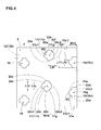
- a motorcycle tire 1 comprises a tread portion 2, a pair of sidewall portions 3, a pair of bead portions 4 each with a bead core 5 therein, a carcass 6 extending between the bead portions 4 through the tread portion 2 and sidewall portions 3, and a tread reinforcing layer 7 disposed radially outside the carcass 6 in the tread portion 2.
- the tread portion 2 is convexly curved so that the tread face between the tread edges 2t is curved like an arc swelling radially outwardly, and the maximum cross sectional width of the tire 1 occurs between the tread edges 2t, namely, equals to the axial tread width TW.
- the motorcycle tire 1 is designed to exert its excellent performance when running on soft grounds such as sand and mud and also relatively hard grounds such as dry earthen road and thus it is suitable for use in a motocross race.
- the carcass 6 is composed of at least one carcass ply 6A, in this embodiment only one carcass ply 6A, extending between the bead portions 4 through the tread portion 2 and sidewall portions 3, and turned up around the bead core 5 in each of the bead portions 4 so as to form a pair of turned up portions 6b and a main portion 6a therebetween.
- the carcass cords organic fiber cords such as nylon, polyester, rayon and the like can be used.
- a radial ply made of organic fiber cords arranged at an angle of from 75 to 90 degrees with respect to the tire circumferential direction can be used.
- a bias ply carcass composed of two or more carcass plies each made of carcass cords arranged at an angle of from 15 to 45 degrees with respect to the tire circumferential direction.
- each of the bead portions 4 between the carcass ply main portion 6a and turned up portion 6b, there is disposed a bead apex 8 made of hard rubber extending radially outwardly in a tapered manner from the bead core.
- the tread reinforcing layer 7 is composed of at least one ply, in this embodiment only one ply 7A, of organic fiber cords laid at an angle of 15 to 45 degrees with respect to the tire circumferential direction.
- the tread portion 2 is provided with a plurality of blocks 11 arranged sparsely as shown in Fig. 2 , and in this embodiment, the land ratio (SL/S) is set in a range of not more than 30 %, preferably not more than 26 %, but not less than 6 %, preferably not less than 10 % in order to increase the digging of the blocks into the soft ground and thereby to produce a large drive power, but not to trap the mud and the like between the blocks.
- the land ratio (SL/S) is as well known in the art, a ratio of the ground contacting area SL (or the total area of the top surfaces of the blocks 11) to the gross area of the tread portion 2.
- the land ratio SL/S becomes more than 30 %, then the ground pressure of the block 11 decreases, and there is a possibility that the digging into the ground becomes insufficient. If the land ratio SL/S becomes less than 6 %, then the edges of the blocks 11 decrease, and there is a possibility that sufficient drive power can not be obtained.
- the bottom 12b of the sea area of the tread portion 2 has a profile which is curved similarly to the profile of the outer surface of the carcass 6.
- the sea area means the area surrounding the blocks 11 and corresponding to the grooved area of the tread portion of a tire for passenger cars, truck/bus and the like.
- the depth D1 of the sea bottom 12b from the tread surface is set in a range of from 9 to 19 mm.
- the block 11 protrudes from the sea bottom 12b and has a top surface having a centroid and defining a part of the tread surface. Accordingly, the depth D1 corresponds to the radial height of the block 11 from the sea bottom 12b to the top surface. If the radial height D1 is less than 9 mm, the digging of the block 11 into the ground becomes decreased, and there is a possibility that sufficient drive power can not be obtained. If the radial height D1 is more than 16 mm, the rigidity of the block 11 decreases, and there is a possibility that sufficient drive power can not be obtained. From this standpoint, the radial height D1 is preferably not less than 10 mm and not more than 15 mm.
- the hardness of the rubber of the block 11 is preferably set in a range of not less than 55 degrees, more preferably not less than 65 degrees, but not more than 95 degrees, more preferably not more than 85 degrees.
- the hardness means a JIS type A durometer hardness measured at 23 deg.c.
- the hardness of the rubber is less than 55 degrees, it becomes difficult for the block 11 to secure sufficient rigidity, and there is a possibility that sufficient drive power can not be obtained. If the hardness of the rubber is more than 95 degrees, it becomes difficult for the block 11 to provide necessarily flexibility.
- the shoulder regions SH are each defined as extending from the tread edge 2t toward the tire equator and having a developed width of 12.5 % of the developed tread width TWe.
- the middle regions MD are defined between the center region Cr and the shoulder regions SH as each having a developed width of 25 % of the developed tread width TWe.
- the top surface 16v of the center block 16 is provided with a pair of axially extending edges 21a which extend straight and parallel with the tire axial direction on its both sides in the tire circumferential direction, and a pair of circumferentially extending edges 21c which extend straight and parallel with the tire circumferential direction on its both sides in the tire axial direction.
- the top surface 16v of the center block 16 is provided on both sides of each of the axially extending edges 21a in the tire axial direction with arc edges 21e curved convexly toward the centroid 16g of the center block 16 so that the axially extending edges 21a protrude oppositely in the tire circumferential direction and the circumferentially extending edges 21c protrude oppositely in the tire axial direction and thereby the top surface has a crisscross shape.
- the maximum axial width W11 and maximum circumferential length L11 of the top surface 16v of the center block 16 have substantially same values.
- Such center block 16 is therefore, increased in the ground pressure on both sides in the tire circumferential direction of the axially extending edge 21a to dig into the ground further more during straight running. Accordingly, it is possible to improve the wandering, traction and braking performance during straight running.
- center block 16 in this embodiment is increased in the ground pressure on both sides in the tire axial direction of the circumferentially extending edge 21c to dig into the ground deeply during cornering, therefore, it is also possible to improve cornering performance.
- the ratio L1a/W11 of the axial length L1a of the axially extending edge 21a of the center block 16 and the maximum width W11 of the top surface 16v of the center block 16 is preferably set in a range of 26 to 46 %.
- the ratio L1a/W11 is more than 46 %, it becomes difficult to significantly increase the ground pressure near the axially extending edge 21a. If the ratio L1a/W11 is less than 26 %, the block rigidity is decreased near the axially extending edge 21a, and it becomes difficult to dig into the ground sufficiently. From this standpoint, the ratio L1a/W11 is more preferably not more than 41 % and not less than 31 %.
- the ratio L1c/L11 of the circumferential length L1c of the circumferentially extending edge 21c of the center block 16 and the maximum length L11 of the top surface 16v of the center block 16 is preferably set in a range of not more than 46 %, more preferably not more than 41 %, but not less than 26 %, more preferably not less than 31 %.
- the ratio R1/L11 of the radius R1 of curvature of the arc edge 21e of the center block 16 and the maximum length L11 of the top surface 16v of the center block 16 is preferably set in a range of from 22 to 42 %.
- the ratio R1/L11 is less than 22 %, the lengths L1a and L1c of the axially extending edge 21a and circumferentially extending edge 21c excessively increase and the ground pressure can not be increased near the edges 21a and 21c. If the ratio R1/L11 is more than 42 %, the block rigidity is excessively decreased near the edges 21a and 21c, and the digging into the ground becomes decreased. From this standpoint, the ratio R1/L11 is more preferably not less than 27 % and not more than 37 %.
- the center blocks 16 include, in addition to independent solo center blocks 16, a plurality of tied center block groups 20 each consisting of at least two, in this embodiment only two of the center blocks 16 which are arranged in line in the tire axial direction and each connected to the next with a tie bar 19 protruding from the sea bottom 12b and extending continuously therebetween.
- the tied center blocks 16 are increased in the apparent rigidity, and the traction and braking performance during straight running can be improved. Further, as the axially extending edges of the tie bars 19 are added, the traction and braking performance when running straight on soft grounds can be improved.
- the tied center block groups 20 are preferably arranged circumferentially of the tire at intervals so that during running at least one of the tied center block groups 20 always exists in the ground contacting patch (or footprint) of the tire under the normally inflated loaded condition. If the number of the tied center block groups 20 is too much, the land ratio (SL/S) increases, and the digging into the ground becomes insufficiently. From this standpoint, the number of the tied center block groups 20 existing in the ground contacting patch is not more than 4.
- the two center blocks 16 are disposed one on each side of the tire equator C so that their centroids (g) become at the same axial distances L6 from the tire equator C.
- the distance L6 is set in a range of from 5 to 10 % of the developed tread width TWe.
- the circumferential length L8 of the tie bar 19 is set to be the same as the length L1c of the circumferentially extending edge 21c of the center block 16.
- the radial height H1 of the tie bar 19 from the sea bottom 12b is set in a range of from 10 to 50 % of the height D1 of the block 11 in order to increase the ground pressure of the center block 16 near the axially extending edges 21a.
- the top surface 17v of the middle block 17 is provided with an axially inside circumferentially extending edge 22c1 which extends straight and parallel with the tire circumferential direction on its tire equator side, an axially outside circumferentially extending edge 22c2 which extends straight and parallel with the tire circumferential direction on its axially outside, and a pair of axially extending edges 22a which extend straight and parallel with the tire axial direction on its both sides in the tire circumferential direction.
- the top surface 17v of the middle block 17 is provided on both sides of the axially inside circumferentially extending edge 22c1 in the tire circumferential direction with arc edges 22e curved convexly toward the centroid 17g.
- oblique edges 22f extending straight and obliquely with respect to the tire circumferential direction are provided. This is preferable to the arc edges in order to maintain the rigidity of the middle block 17 at a higher level than the center block.
- the axial length L2f of the oblique edge 22f is preferably set in a range of from 25 to 35 % of the maximum width W12 of the top surface 17v of the middle block 17.
- the axially inside circumferentially extending edge 22c1 protrudes toward the tire equator, and the top surface 17v of the middle block 17 has a T-shape.
- the maximum axial width W12 and maximum circumferential length L12 of the top surface 17v of the middle block 17 have substantially same values.
- Such middle block 17 can increase the ground pressure of the top surface 17v near the axially inside circumferentially extending edge 22c1, therefore the higher ground pressure part digs into the ground more during cornering and cornering performance can be improved.
- the ratio L2c/L12 of the circumferential length L2c of the axially inside circumferentially extending edge 22c1 of the middle block 17 and the maximum length L12 of the top surface 17v of the middle block 17 is preferably set in a range of from 27 to 47 %. If the ratio L2c/L12 is more than 47 %, it becomes difficult to increase the ground pressure near the axially inside circumferentially extending edge 22c1. If the ratio L2c/L12 is less than 27 %, the block rigidity is excessively decreased near the axially inside circumferentially extending edge 22c1. From this standpoint, the ratio L2c/L12 is more preferably not more than 42 % and not less than 32 %.
- the ratio R2/W12 of the radius R2 of curvature of the arc edge 22e of the middle block 17 and the maximum width W12 of the top surface 17v of the middle block 17 is preferably set in a range of not less than 22 %, more preferably not less than 27 %, but not more than 42 %, more preferably not more than 37 %.
- the centroids 17g of the middle blocks 17 which are arranged circumferentially of the tire are disposed at two or more different axial positions as shown in Fig. 2 in order to improve transient characteristics from straight running to cornering or vice versa.
- each of the centroids 17g of the middle blocks 17 in each of the middle regions MD is preferably disposed at a different axial position than those of the circumferentially adjacent centroids 17g.
- the middle blocks are arranged in line in the tire circumferential direction, or the centroids 17g of the middle blocks 17 in each of the middle regions MD are disposed at the same axial position.
- the ratio L7/0.5TWe of the axial distance L7 from the tire equator C to the centroid 17g of the middle block 17 and one half of the developed tread width 0.5TWe is preferably set in a range of not less than 38 %, more preferably not less than 48 %, but not more than 68 %.
- the ratio L7/0.5TWe is less than 38 %, it becomes difficult for the middle blocks 17 to make a contribution to improvement in the grip performance in full bank cornering. If the ratio L7/0.5TWe is more than 68 %, it becomes difficult for the middle blocks 17 to make a contribution to improvement in the grip performance in straight running and the transient state between straight running and cornering.
- the middle blocks 17 in this embodiment with respect to the circumferential positions of the centroids, the middle blocks 17a in one middle region MDa are respectively aligned with the middle blocks 17b in the other middle region MDb so that the angle of a straight line LN1 drawn between the centroids 17ga and 17gb of every two aligned middle blocks 17a and 17b becomes not more than 10 degrees, preferably not more than 5 degrees, most preferably 0 degree with respect to the tire axial direction. Therefore, the middle block 17a and middle block 17b can contact with the ground simultaneously to prevent wandering.
- the top surface 18v of the shoulder block 18 is provided with a pair of axially extending edges 23a which extend straight and parallel with the tire axial direction on its both sides in the tire circumferential direction, an axially inside circumferentially extending edge 23c1 which extends straight and parallel with the tire circumferential direction on its tire equator side, an axially outside circumferentially extending edge 23c2 which extends straight and parallel with the tire circumferential direction on its axially outside, and a pair of arc edges 23e which are curved convexly toward the centroid on both sides of the axially inside circumferentially extending edge 23c1 in the tire circumferential direction.
- the oblique edge 22f in the middle block 17 is not provided in order to increase the rigidity of the shoulder block 18 than the middle block 17.
- the axially inside circumferentially extending edge 23c1 protrudes toward the tire equator, and the top surface 18v of the shoulder block 18 has a T shape.
- the shoulder block 18 is formed such that the maximum circumferential length L13 of the top surface 18v is more than (about 110 to 140 %) the maximum axial width W13 of the top surface 18v.
- the ground pressure of the shoulder block 18 is increased near the axially inside circumferentially extending edge 23c1, and this part digs into the ground more to improve the cornering performance.
- the ratio L3c/L13 of the circumferential length L3c of the axially inside circumferentially extending edge 23c1 of the shoulder block 18 and the maximum length L13 of the top surface 18v of the shoulder block 18 is preferably set in a range of not more than 46 %, more preferably not more than 41 %, but not less than 26 %, more preferably not less than 31 %.
- the ratio R3/W13 of the radius R3 of curvature of the arc edge 23e of the shoulder block 18 and the maximum width W13 of the top surface 18v of the shoulder block 18 is preferably set in a range of not less than 29 %, more preferably not less than 34 %, but not more than 49 %, more preferably not more than 44 %.
- the shoulder blocks 18a in one shoulder region SHa are respectively aligned with the shoulder blocks 18b in the other shoulder region SHb so that the angle of a straight line LN2 drawn between the centroids 18g1 and 18g2 of every two aligned shoulder blocks 18a and 18b becomes not more than 8 degrees, preferably not more than 4 degrees, most preferably 0 degree with respect to the tire axial direction. Therefore, the shoulder block 18a and shoulder block 18b can contact with the ground simultaneously when running on soft ground or when running under a low tire pressure condition and thereby wandering can be prevented.
- the tied center block groups 20 each consists of two center blocks 16 arranged such that the circumferentially extending edges 21c of the center blocks 16 are aligned with the border lines of the tread center region Cr. In other words, the groups 20 extends over the entire width of the tread center region Cr. Between the circumferentially adjacent groups 20, two solo center blocks 16 are disposed on the tire equator C. The solo center blocks 16 and the groups 20 are disposed at substantially even intervals in the tire circumferential direction.
- the middle blocks 17 in each middle region MD are disposed at four different axial positions.
- the axially outermost middle blocks 17 are aligned with every two groups 20 with respect to the circumferential positions. Between the circumferentially adjacent groups 20, three middle blocks 17 are disposed at three different axial positions. As a result, the middle blocks 17 in each middle region MD are disposed along a wavy line.
- the shoulder blocks 18 are disposed along the tread edges.
- the shoulder blocks 18 in each shoulder region SH are those aligned with every two groups 20 which are not aligned with the axially outermost middle blocks 17, and two shoulder blocks disposed between every two circumferentially adjacent groups 20.
- cross sections of the block parallel to the top surface are gradually increased in the area, having similar figures to the top surface.
- the increase in the area is linear from the top surface to a radial height of about 15 to 20 % of the radial height D1, then the increase is at an accelerated rate to the sea bottom.
- the maximum width W11 of the top surface 16v of the center block 16 is about one third (30 to 36 %) of the developed width of the center region Cr.
- the maximum width W12 of the top surface 17v of the middle block 17 is substantially same as the maximum width W11 of the center block 16.
- the maximum axial width W13 of the top surface 18v of the shoulder block 18 is substantially same as or slightly smaller than (100 to 80 %) the maximum width W11 of the center block 16.
- All of the blocks have almost same sizes such that the maximum top surface area is less than 150 % of the minimum top surface area.
- Test tires having the internal structure shown in Fig. 1 and blocks whose specifications are shown in Table 1 were experimentally manufactured and tested.
Landscapes
- Engineering & Computer Science (AREA)
- Mechanical Engineering (AREA)
- Tires In General (AREA)
Applications Claiming Priority (1)
| Application Number | Priority Date | Filing Date | Title |
|---|---|---|---|
| JP2011155076 | 2011-07-13 |
Publications (2)
| Publication Number | Publication Date |
|---|---|
| EP2546079A1 true EP2546079A1 (fr) | 2013-01-16 |
| EP2546079B1 EP2546079B1 (fr) | 2015-09-23 |
Family
ID=46319592
Family Applications (1)
| Application Number | Title | Priority Date | Filing Date |
|---|---|---|---|
| EP12172108.8A Active EP2546079B1 (fr) | 2011-07-13 | 2012-06-15 | Pneu de motocyclette pour terrain accidenté |
Country Status (7)
| Country | Link |
|---|---|
| US (1) | US9375982B2 (fr) |
| EP (1) | EP2546079B1 (fr) |
| JP (1) | JP5320491B2 (fr) |
| KR (1) | KR101773625B1 (fr) |
| CN (1) | CN102874056B (fr) |
| AU (1) | AU2012203456B2 (fr) |
| BR (1) | BR102012017433B1 (fr) |
Cited By (2)
| Publication number | Priority date | Publication date | Assignee | Title |
|---|---|---|---|---|
| EP3323641A1 (fr) * | 2016-11-22 | 2018-05-23 | Sumitomo Rubber Industries, Ltd. | Pneu de motocyclette pour terrains accidentés |
| EP3747671A4 (fr) * | 2018-02-02 | 2021-10-06 | Bridgestone Corporation | Pneu de motocyclette |
Families Citing this family (12)
| Publication number | Priority date | Publication date | Assignee | Title |
|---|---|---|---|---|
| US10182757B2 (en) | 2013-07-22 | 2019-01-22 | The Rockefeller University | System and method for optical detection of skin disease |
| TWI560078B (en) * | 2013-10-16 | 2016-12-01 | Lg Chemical Ltd | Apparatus for manufacturing blanket and method for manufacturing blanket |
| JP5957429B2 (ja) * | 2013-10-16 | 2016-07-27 | 住友ゴム工業株式会社 | 不整地走行用の自動二輪車用タイヤ |
| JP6193731B2 (ja) * | 2013-11-07 | 2017-09-06 | 住友ゴム工業株式会社 | 不整地走行用空気入りタイヤ |
| CN105992696B (zh) * | 2013-11-29 | 2019-02-19 | Lg化学株式会社 | 印刷用毯及该毯的制造方法 |
| JP6420674B2 (ja) * | 2015-01-26 | 2018-11-07 | 住友ゴム工業株式会社 | 不整地走行用の自動二輪車用タイヤ |
| US11134885B2 (en) | 2015-08-13 | 2021-10-05 | The Rockefeller University | Quantitative dermoscopic melanoma screening |
| JP6838362B2 (ja) * | 2016-11-17 | 2021-03-03 | 住友ゴム工業株式会社 | 二輪車用タイヤ及び自動二輪車 |
| JP7087427B2 (ja) * | 2018-02-08 | 2022-06-21 | 住友ゴム工業株式会社 | 二輪車用タイヤ |
| JP7124531B2 (ja) * | 2018-08-01 | 2022-08-24 | 住友ゴム工業株式会社 | 不整地走行用のタイヤ |
| EP3795387B1 (fr) * | 2018-08-09 | 2023-06-07 | Bridgestone Corporation | Pneu de motocyclette |
| JP7505250B2 (ja) | 2020-05-11 | 2024-06-25 | 住友ゴム工業株式会社 | 不整地走行用モーターサイクルタイヤ |
Citations (4)
| Publication number | Priority date | Publication date | Assignee | Title |
|---|---|---|---|---|
| US1223049A (en) * | 1916-09-12 | 1917-04-17 | Olie J Hicks | Automobile-tire. |
| JPS57138403A (en) * | 1981-02-16 | 1982-08-26 | Sumitomo Rubber Ind Ltd | Tire equipped with improved tread pattern |
| DE202004006512U1 (de) * | 2004-02-06 | 2004-07-01 | The Goodyear Tire & Rubber Co., Akron | Motorradreifen, insbesondere auch für den off-road-Einsatz oder als Motorcross-Reifen |
| EP2204295A1 (fr) * | 2007-09-13 | 2010-07-07 | Sumitomo Rubber Industries, Ltd. | Pneumatique tout terrain |
Family Cites Families (11)
| Publication number | Priority date | Publication date | Assignee | Title |
|---|---|---|---|---|
| CA1104046A (fr) * | 1978-11-27 | 1981-06-30 | Toshio Hayakawa | Pneu de motocross |
| JPS5845104U (ja) * | 1981-09-21 | 1983-03-26 | 住友ゴム工業株式会社 | タイヤトレツドパタ−ン |
| JPH066005U (ja) * | 1992-07-02 | 1994-01-25 | 株式会社ブリヂストン | モーターサイクル用タイヤ |
| CN2220382Y (zh) * | 1995-01-20 | 1996-02-21 | 杨长易 | 防滑轮胎 |
| JP3363434B2 (ja) * | 2000-07-21 | 2003-01-08 | 住友ゴム工業株式会社 | 不整地走行用の空気入りタイヤ |
| JP4037629B2 (ja) * | 2001-08-31 | 2008-01-23 | 住友ゴム工業株式会社 | 不整地走行用の空気入りタイヤ |
| JP2006027567A (ja) * | 2004-07-21 | 2006-02-02 | Yokohama Rubber Co Ltd:The | 空気入りタイヤ |
| JP4690852B2 (ja) * | 2005-10-24 | 2011-06-01 | 住友ゴム工業株式会社 | 空気入りタイヤ |
| JP4312226B2 (ja) * | 2006-11-15 | 2009-08-12 | 住友ゴム工業株式会社 | 不整地走行用の空気入りタイヤ |
| CN102781686B (zh) * | 2010-01-27 | 2015-02-18 | 普利司通美国轮胎运营有限责任公司 | 具有降低噪音的胎面花纹的轮胎 |
| JP5039191B2 (ja) * | 2010-08-26 | 2012-10-03 | 住友ゴム工業株式会社 | 不整地走行用の自動二輪車用タイヤ |
-
2012
- 2012-06-07 JP JP2012130121A patent/JP5320491B2/ja not_active Expired - Fee Related
- 2012-06-13 AU AU2012203456A patent/AU2012203456B2/en active Active
- 2012-06-15 EP EP12172108.8A patent/EP2546079B1/fr active Active
- 2012-06-21 US US13/529,323 patent/US9375982B2/en not_active Expired - Fee Related
- 2012-06-21 KR KR1020120066778A patent/KR101773625B1/ko active IP Right Grant
- 2012-06-26 CN CN201210215041.3A patent/CN102874056B/zh not_active Expired - Fee Related
- 2012-07-13 BR BR102012017433-2A patent/BR102012017433B1/pt not_active IP Right Cessation
Patent Citations (4)
| Publication number | Priority date | Publication date | Assignee | Title |
|---|---|---|---|---|
| US1223049A (en) * | 1916-09-12 | 1917-04-17 | Olie J Hicks | Automobile-tire. |
| JPS57138403A (en) * | 1981-02-16 | 1982-08-26 | Sumitomo Rubber Ind Ltd | Tire equipped with improved tread pattern |
| DE202004006512U1 (de) * | 2004-02-06 | 2004-07-01 | The Goodyear Tire & Rubber Co., Akron | Motorradreifen, insbesondere auch für den off-road-Einsatz oder als Motorcross-Reifen |
| EP2204295A1 (fr) * | 2007-09-13 | 2010-07-07 | Sumitomo Rubber Industries, Ltd. | Pneumatique tout terrain |
Non-Patent Citations (1)
| Title |
|---|
| ANONYMOUS: "Tire Review: Dunlop D908 Rally Raid", 6 June 2008 (2008-06-06), XP002685221, Retrieved from the Internet <URL:http://itsallaboutthebike.com/tire-review-dunlop-d908-rally-raid/> [retrieved on 20121015] * |
Cited By (3)
| Publication number | Priority date | Publication date | Assignee | Title |
|---|---|---|---|---|
| EP3323641A1 (fr) * | 2016-11-22 | 2018-05-23 | Sumitomo Rubber Industries, Ltd. | Pneu de motocyclette pour terrains accidentés |
| US10899180B2 (en) | 2016-11-22 | 2021-01-26 | Sumitomo Rubber Industries, Ltd. | Motorcycle tire for running on rough terrain |
| EP3747671A4 (fr) * | 2018-02-02 | 2021-10-06 | Bridgestone Corporation | Pneu de motocyclette |
Also Published As
| Publication number | Publication date |
|---|---|
| AU2012203456A1 (en) | 2013-01-31 |
| EP2546079B1 (fr) | 2015-09-23 |
| CN102874056B (zh) | 2016-05-11 |
| JP2013035537A (ja) | 2013-02-21 |
| KR20130009613A (ko) | 2013-01-23 |
| AU2012203456B2 (en) | 2014-09-04 |
| KR101773625B1 (ko) | 2017-08-31 |
| BR102012017433A2 (pt) | 2013-12-03 |
| US9375982B2 (en) | 2016-06-28 |
| BR102012017433B1 (pt) | 2020-11-17 |
| JP5320491B2 (ja) | 2013-10-23 |
| US20130014868A1 (en) | 2013-01-17 |
| CN102874056A (zh) | 2013-01-16 |
Similar Documents
| Publication | Publication Date | Title |
|---|---|---|
| EP2546079A1 (fr) | Pneu de motocyclette pour terrain accidenté | |
| US8950452B2 (en) | Motorcycle tire for running on rough terrain | |
| EP2412546B1 (fr) | Pneu de motocyclette pour terrains accidentés | |
| US9352620B2 (en) | Motorcycle tire for running on rough terrain | |
| US9643457B2 (en) | Pneumatic tire | |
| US9688103B2 (en) | Motorcycle tire | |
| US9457622B2 (en) | Pneumatic tire | |
| US9868324B2 (en) | Motorcycle tire | |
| US8925601B2 (en) | Pneumatic tire | |
| JP5841568B2 (ja) | 空気入りタイヤ | |
| EP2390114B1 (fr) | Pneu de motocyclette pour terrains accidentés | |
| US9340072B2 (en) | Motorcycle tire | |
| US9623709B2 (en) | Pneumatic tire for running on rough terrain | |
| US9573424B2 (en) | Motorcycle tire | |
| US20120060990A1 (en) | Pneumatic tire | |
| US20120312437A1 (en) | Motorcycle tire | |
| JP2009298262A (ja) | 空気入りタイヤ |
Legal Events
| Date | Code | Title | Description |
|---|---|---|---|
| PUAI | Public reference made under article 153(3) epc to a published international application that has entered the european phase |
Free format text: ORIGINAL CODE: 0009012 |
|
| AK | Designated contracting states |
Kind code of ref document: A1 Designated state(s): AL AT BE BG CH CY CZ DE DK EE ES FI FR GB GR HR HU IE IS IT LI LT LU LV MC MK MT NL NO PL PT RO RS SE SI SK SM TR |
|
| AX | Request for extension of the european patent |
Extension state: BA ME |
|
| 17P | Request for examination filed |
Effective date: 20130711 |
|
| RBV | Designated contracting states (corrected) |
Designated state(s): AL AT BE BG CH CY CZ DE DK EE ES FI FR GB GR HR HU IE IS IT LI LT LU LV MC MK MT NL NO PL PT RO RS SE SI SK SM TR |
|
| GRAP | Despatch of communication of intention to grant a patent |
Free format text: ORIGINAL CODE: EPIDOSNIGR1 |
|
| INTG | Intention to grant announced |
Effective date: 20150703 |
|
| GRAS | Grant fee paid |
Free format text: ORIGINAL CODE: EPIDOSNIGR3 |
|
| GRAA | (expected) grant |
Free format text: ORIGINAL CODE: 0009210 |
|
| AK | Designated contracting states |
Kind code of ref document: B1 Designated state(s): AL AT BE BG CH CY CZ DE DK EE ES FI FR GB GR HR HU IE IS IT LI LT LU LV MC MK MT NL NO PL PT RO RS SE SI SK SM TR |
|
| REG | Reference to a national code |
Ref country code: GB Ref legal event code: FG4D |
|
| REG | Reference to a national code |
Ref country code: CH Ref legal event code: EP |
|
| REG | Reference to a national code |
Ref country code: AT Ref legal event code: REF Ref document number: 751027 Country of ref document: AT Kind code of ref document: T Effective date: 20151015 |
|
| REG | Reference to a national code |
Ref country code: IE Ref legal event code: FG4D |
|
| REG | Reference to a national code |
Ref country code: DE Ref legal event code: R096 Ref document number: 602012010889 Country of ref document: DE |
|
| REG | Reference to a national code |
Ref country code: NL Ref legal event code: MP Effective date: 20150923 |
|
| PG25 | Lapsed in a contracting state [announced via postgrant information from national office to epo] |
Ref country code: GR Free format text: LAPSE BECAUSE OF FAILURE TO SUBMIT A TRANSLATION OF THE DESCRIPTION OR TO PAY THE FEE WITHIN THE PRESCRIBED TIME-LIMIT Effective date: 20151224 Ref country code: FI Free format text: LAPSE BECAUSE OF FAILURE TO SUBMIT A TRANSLATION OF THE DESCRIPTION OR TO PAY THE FEE WITHIN THE PRESCRIBED TIME-LIMIT Effective date: 20150923 Ref country code: NO Free format text: LAPSE BECAUSE OF FAILURE TO SUBMIT A TRANSLATION OF THE DESCRIPTION OR TO PAY THE FEE WITHIN THE PRESCRIBED TIME-LIMIT Effective date: 20151223 Ref country code: LT Free format text: LAPSE BECAUSE OF FAILURE TO SUBMIT A TRANSLATION OF THE DESCRIPTION OR TO PAY THE FEE WITHIN THE PRESCRIBED TIME-LIMIT Effective date: 20150923 Ref country code: LV Free format text: LAPSE BECAUSE OF FAILURE TO SUBMIT A TRANSLATION OF THE DESCRIPTION OR TO PAY THE FEE WITHIN THE PRESCRIBED TIME-LIMIT Effective date: 20150923 |
|
| REG | Reference to a national code |
Ref country code: LT Ref legal event code: MG4D |
|
| REG | Reference to a national code |
Ref country code: AT Ref legal event code: MK05 Ref document number: 751027 Country of ref document: AT Kind code of ref document: T Effective date: 20150923 |
|
| PG25 | Lapsed in a contracting state [announced via postgrant information from national office to epo] |
Ref country code: RS Free format text: LAPSE BECAUSE OF FAILURE TO SUBMIT A TRANSLATION OF THE DESCRIPTION OR TO PAY THE FEE WITHIN THE PRESCRIBED TIME-LIMIT Effective date: 20150923 Ref country code: SE Free format text: LAPSE BECAUSE OF FAILURE TO SUBMIT A TRANSLATION OF THE DESCRIPTION OR TO PAY THE FEE WITHIN THE PRESCRIBED TIME-LIMIT Effective date: 20150923 Ref country code: HR Free format text: LAPSE BECAUSE OF FAILURE TO SUBMIT A TRANSLATION OF THE DESCRIPTION OR TO PAY THE FEE WITHIN THE PRESCRIBED TIME-LIMIT Effective date: 20150923 |
|
| PG25 | Lapsed in a contracting state [announced via postgrant information from national office to epo] |
Ref country code: NL Free format text: LAPSE BECAUSE OF FAILURE TO SUBMIT A TRANSLATION OF THE DESCRIPTION OR TO PAY THE FEE WITHIN THE PRESCRIBED TIME-LIMIT Effective date: 20150923 |
|
| PG25 | Lapsed in a contracting state [announced via postgrant information from national office to epo] |
Ref country code: CZ Free format text: LAPSE BECAUSE OF FAILURE TO SUBMIT A TRANSLATION OF THE DESCRIPTION OR TO PAY THE FEE WITHIN THE PRESCRIBED TIME-LIMIT Effective date: 20150923 Ref country code: IS Free format text: LAPSE BECAUSE OF FAILURE TO SUBMIT A TRANSLATION OF THE DESCRIPTION OR TO PAY THE FEE WITHIN THE PRESCRIBED TIME-LIMIT Effective date: 20160123 Ref country code: SK Free format text: LAPSE BECAUSE OF FAILURE TO SUBMIT A TRANSLATION OF THE DESCRIPTION OR TO PAY THE FEE WITHIN THE PRESCRIBED TIME-LIMIT Effective date: 20150923 Ref country code: EE Free format text: LAPSE BECAUSE OF FAILURE TO SUBMIT A TRANSLATION OF THE DESCRIPTION OR TO PAY THE FEE WITHIN THE PRESCRIBED TIME-LIMIT Effective date: 20150923 Ref country code: ES Free format text: LAPSE BECAUSE OF FAILURE TO SUBMIT A TRANSLATION OF THE DESCRIPTION OR TO PAY THE FEE WITHIN THE PRESCRIBED TIME-LIMIT Effective date: 20150923 |
|
| PG25 | Lapsed in a contracting state [announced via postgrant information from national office to epo] |
Ref country code: RO Free format text: LAPSE BECAUSE OF FAILURE TO SUBMIT A TRANSLATION OF THE DESCRIPTION OR TO PAY THE FEE WITHIN THE PRESCRIBED TIME-LIMIT Effective date: 20150923 Ref country code: AT Free format text: LAPSE BECAUSE OF FAILURE TO SUBMIT A TRANSLATION OF THE DESCRIPTION OR TO PAY THE FEE WITHIN THE PRESCRIBED TIME-LIMIT Effective date: 20150923 Ref country code: PT Free format text: LAPSE BECAUSE OF FAILURE TO SUBMIT A TRANSLATION OF THE DESCRIPTION OR TO PAY THE FEE WITHIN THE PRESCRIBED TIME-LIMIT Effective date: 20160125 Ref country code: PL Free format text: LAPSE BECAUSE OF FAILURE TO SUBMIT A TRANSLATION OF THE DESCRIPTION OR TO PAY THE FEE WITHIN THE PRESCRIBED TIME-LIMIT Effective date: 20150923 |
|
| REG | Reference to a national code |
Ref country code: DE Ref legal event code: R097 Ref document number: 602012010889 Country of ref document: DE |
|
| REG | Reference to a national code |
Ref country code: FR Ref legal event code: PLFP Year of fee payment: 5 |
|
| PLBE | No opposition filed within time limit |
Free format text: ORIGINAL CODE: 0009261 |
|
| STAA | Information on the status of an ep patent application or granted ep patent |
Free format text: STATUS: NO OPPOSITION FILED WITHIN TIME LIMIT |
|
| 26N | No opposition filed |
Effective date: 20160624 |
|
| PG25 | Lapsed in a contracting state [announced via postgrant information from national office to epo] |
Ref country code: DK Free format text: LAPSE BECAUSE OF FAILURE TO SUBMIT A TRANSLATION OF THE DESCRIPTION OR TO PAY THE FEE WITHIN THE PRESCRIBED TIME-LIMIT Effective date: 20150923 |
|
| PG25 | Lapsed in a contracting state [announced via postgrant information from national office to epo] |
Ref country code: SI Free format text: LAPSE BECAUSE OF FAILURE TO SUBMIT A TRANSLATION OF THE DESCRIPTION OR TO PAY THE FEE WITHIN THE PRESCRIBED TIME-LIMIT Effective date: 20150923 |
|
| PG25 | Lapsed in a contracting state [announced via postgrant information from national office to epo] |
Ref country code: BE Free format text: LAPSE BECAUSE OF FAILURE TO SUBMIT A TRANSLATION OF THE DESCRIPTION OR TO PAY THE FEE WITHIN THE PRESCRIBED TIME-LIMIT Effective date: 20150923 |
|
| PG25 | Lapsed in a contracting state [announced via postgrant information from national office to epo] |
Ref country code: MC Free format text: LAPSE BECAUSE OF FAILURE TO SUBMIT A TRANSLATION OF THE DESCRIPTION OR TO PAY THE FEE WITHIN THE PRESCRIBED TIME-LIMIT Effective date: 20150923 |
|
| REG | Reference to a national code |
Ref country code: CH Ref legal event code: PL |
|
| GBPC | Gb: european patent ceased through non-payment of renewal fee |
Effective date: 20160615 |
|
| REG | Reference to a national code |
Ref country code: IE Ref legal event code: MM4A |
|
| PG25 | Lapsed in a contracting state [announced via postgrant information from national office to epo] |
Ref country code: LI Free format text: LAPSE BECAUSE OF NON-PAYMENT OF DUE FEES Effective date: 20160630 Ref country code: CH Free format text: LAPSE BECAUSE OF NON-PAYMENT OF DUE FEES Effective date: 20160630 |
|
| REG | Reference to a national code |
Ref country code: FR Ref legal event code: PLFP Year of fee payment: 6 |
|
| PG25 | Lapsed in a contracting state [announced via postgrant information from national office to epo] |
Ref country code: IE Free format text: LAPSE BECAUSE OF NON-PAYMENT OF DUE FEES Effective date: 20160615 Ref country code: GB Free format text: LAPSE BECAUSE OF NON-PAYMENT OF DUE FEES Effective date: 20160615 |
|
| REG | Reference to a national code |
Ref country code: FR Ref legal event code: PLFP Year of fee payment: 7 |
|
| PG25 | Lapsed in a contracting state [announced via postgrant information from national office to epo] |
Ref country code: HU Free format text: LAPSE BECAUSE OF FAILURE TO SUBMIT A TRANSLATION OF THE DESCRIPTION OR TO PAY THE FEE WITHIN THE PRESCRIBED TIME-LIMIT; INVALID AB INITIO Effective date: 20120615 Ref country code: CY Free format text: LAPSE BECAUSE OF FAILURE TO SUBMIT A TRANSLATION OF THE DESCRIPTION OR TO PAY THE FEE WITHIN THE PRESCRIBED TIME-LIMIT Effective date: 20150923 Ref country code: SM Free format text: LAPSE BECAUSE OF FAILURE TO SUBMIT A TRANSLATION OF THE DESCRIPTION OR TO PAY THE FEE WITHIN THE PRESCRIBED TIME-LIMIT Effective date: 20150923 |
|
| PG25 | Lapsed in a contracting state [announced via postgrant information from national office to epo] |
Ref country code: MT Free format text: LAPSE BECAUSE OF NON-PAYMENT OF DUE FEES Effective date: 20160630 Ref country code: MK Free format text: LAPSE BECAUSE OF FAILURE TO SUBMIT A TRANSLATION OF THE DESCRIPTION OR TO PAY THE FEE WITHIN THE PRESCRIBED TIME-LIMIT Effective date: 20150923 Ref country code: TR Free format text: LAPSE BECAUSE OF FAILURE TO SUBMIT A TRANSLATION OF THE DESCRIPTION OR TO PAY THE FEE WITHIN THE PRESCRIBED TIME-LIMIT Effective date: 20150923 Ref country code: LU Free format text: LAPSE BECAUSE OF NON-PAYMENT OF DUE FEES Effective date: 20160615 |
|
| PG25 | Lapsed in a contracting state [announced via postgrant information from national office to epo] |
Ref country code: BG Free format text: LAPSE BECAUSE OF FAILURE TO SUBMIT A TRANSLATION OF THE DESCRIPTION OR TO PAY THE FEE WITHIN THE PRESCRIBED TIME-LIMIT Effective date: 20150923 |
|
| PG25 | Lapsed in a contracting state [announced via postgrant information from national office to epo] |
Ref country code: AL Free format text: LAPSE BECAUSE OF FAILURE TO SUBMIT A TRANSLATION OF THE DESCRIPTION OR TO PAY THE FEE WITHIN THE PRESCRIBED TIME-LIMIT Effective date: 20150923 |
|
| P01 | Opt-out of the competence of the unified patent court (upc) registered |
Effective date: 20230510 |
|
| PGFP | Annual fee paid to national office [announced via postgrant information from national office to epo] |
Ref country code: IT Payment date: 20230510 Year of fee payment: 12 Ref country code: FR Payment date: 20230510 Year of fee payment: 12 Ref country code: DE Payment date: 20230502 Year of fee payment: 12 |